EP2649431B1 - Systeme et procede d'imagerie multitechniques pour l'analyse chimique, biologique ou biochiimique d'un echantillon. - Google Patents
Systeme et procede d'imagerie multitechniques pour l'analyse chimique, biologique ou biochiimique d'un echantillon. Download PDFInfo
- Publication number
- EP2649431B1 EP2649431B1 EP11805108.5A EP11805108A EP2649431B1 EP 2649431 B1 EP2649431 B1 EP 2649431B1 EP 11805108 A EP11805108 A EP 11805108A EP 2649431 B1 EP2649431 B1 EP 2649431B1
- Authority
- EP
- European Patent Office
- Prior art keywords
- sample
- light beam
- objective
- source
- optical
- Prior art date
- Legal status (The legal status is an assumption and is not a legal conclusion. Google has not performed a legal analysis and makes no representation as to the accuracy of the status listed.)
- Not-in-force
Links
Images
Classifications
-
- G—PHYSICS
- G01—MEASURING; TESTING
- G01N—INVESTIGATING OR ANALYSING MATERIALS BY DETERMINING THEIR CHEMICAL OR PHYSICAL PROPERTIES
- G01N21/00—Investigating or analysing materials by the use of optical means, i.e. using sub-millimetre waves, infrared, visible or ultraviolet light
- G01N21/17—Systems in which incident light is modified in accordance with the properties of the material investigated
- G01N21/25—Colour; Spectral properties, i.e. comparison of effect of material on the light at two or more different wavelengths or wavelength bands
- G01N21/27—Colour; Spectral properties, i.e. comparison of effect of material on the light at two or more different wavelengths or wavelength bands using photo-electric detection ; circuits for computing concentration
-
- G—PHYSICS
- G01—MEASURING; TESTING
- G01N—INVESTIGATING OR ANALYSING MATERIALS BY DETERMINING THEIR CHEMICAL OR PHYSICAL PROPERTIES
- G01N21/00—Investigating or analysing materials by the use of optical means, i.e. using sub-millimetre waves, infrared, visible or ultraviolet light
- G01N21/17—Systems in which incident light is modified in accordance with the properties of the material investigated
- G01N21/55—Specular reflectivity
- G01N21/552—Attenuated total reflection
- G01N21/553—Attenuated total reflection and using surface plasmons
- G01N21/554—Attenuated total reflection and using surface plasmons detecting the surface plasmon resonance of nanostructured metals, e.g. localised surface plasmon resonance
-
- G—PHYSICS
- G01—MEASURING; TESTING
- G01N—INVESTIGATING OR ANALYSING MATERIALS BY DETERMINING THEIR CHEMICAL OR PHYSICAL PROPERTIES
- G01N21/00—Investigating or analysing materials by the use of optical means, i.e. using sub-millimetre waves, infrared, visible or ultraviolet light
- G01N21/62—Systems in which the material investigated is excited whereby it emits light or causes a change in wavelength of the incident light
- G01N21/63—Systems in which the material investigated is excited whereby it emits light or causes a change in wavelength of the incident light optically excited
- G01N21/64—Fluorescence; Phosphorescence
- G01N21/645—Specially adapted constructive features of fluorimeters
- G01N21/6456—Spatial resolved fluorescence measurements; Imaging
-
- G—PHYSICS
- G01—MEASURING; TESTING
- G01N—INVESTIGATING OR ANALYSING MATERIALS BY DETERMINING THEIR CHEMICAL OR PHYSICAL PROPERTIES
- G01N21/00—Investigating or analysing materials by the use of optical means, i.e. using sub-millimetre waves, infrared, visible or ultraviolet light
- G01N21/62—Systems in which the material investigated is excited whereby it emits light or causes a change in wavelength of the incident light
- G01N21/63—Systems in which the material investigated is excited whereby it emits light or causes a change in wavelength of the incident light optically excited
- G01N21/65—Raman scattering
-
- G—PHYSICS
- G02—OPTICS
- G02B—OPTICAL ELEMENTS, SYSTEMS OR APPARATUS
- G02B21/00—Microscopes
- G02B21/06—Means for illuminating specimens
- G02B21/08—Condensers
- G02B21/082—Condensers for incident illumination only
-
- G—PHYSICS
- G02—OPTICS
- G02B—OPTICAL ELEMENTS, SYSTEMS OR APPARATUS
- G02B21/00—Microscopes
- G02B21/16—Microscopes adapted for ultraviolet illumination ; Fluorescence microscopes
-
- G—PHYSICS
- G01—MEASURING; TESTING
- G01N—INVESTIGATING OR ANALYSING MATERIALS BY DETERMINING THEIR CHEMICAL OR PHYSICAL PROPERTIES
- G01N21/00—Investigating or analysing materials by the use of optical means, i.e. using sub-millimetre waves, infrared, visible or ultraviolet light
- G01N21/62—Systems in which the material investigated is excited whereby it emits light or causes a change in wavelength of the incident light
- G01N21/63—Systems in which the material investigated is excited whereby it emits light or causes a change in wavelength of the incident light optically excited
- G01N21/64—Fluorescence; Phosphorescence
- G01N21/645—Specially adapted constructive features of fluorimeters
- G01N2021/6463—Optics
- G01N2021/6471—Special filters, filter wheel
-
- G—PHYSICS
- G01—MEASURING; TESTING
- G01N—INVESTIGATING OR ANALYSING MATERIALS BY DETERMINING THEIR CHEMICAL OR PHYSICAL PROPERTIES
- G01N21/00—Investigating or analysing materials by the use of optical means, i.e. using sub-millimetre waves, infrared, visible or ultraviolet light
- G01N21/62—Systems in which the material investigated is excited whereby it emits light or causes a change in wavelength of the incident light
- G01N21/63—Systems in which the material investigated is excited whereby it emits light or causes a change in wavelength of the incident light optically excited
- G01N21/64—Fluorescence; Phosphorescence
- G01N2021/6491—Measuring fluorescence and transmission; Correcting inner filter effect
- G01N2021/6493—Measuring fluorescence and transmission; Correcting inner filter effect by alternating fluorescence/transmission or fluorescence/reflection
-
- G—PHYSICS
- G01—MEASURING; TESTING
- G01N—INVESTIGATING OR ANALYSING MATERIALS BY DETERMINING THEIR CHEMICAL OR PHYSICAL PROPERTIES
- G01N21/00—Investigating or analysing materials by the use of optical means, i.e. using sub-millimetre waves, infrared, visible or ultraviolet light
- G01N21/62—Systems in which the material investigated is excited whereby it emits light or causes a change in wavelength of the incident light
- G01N21/63—Systems in which the material investigated is excited whereby it emits light or causes a change in wavelength of the incident light optically excited
- G01N21/64—Fluorescence; Phosphorescence
- G01N21/645—Specially adapted constructive features of fluorimeters
- G01N21/6456—Spatial resolved fluorescence measurements; Imaging
- G01N21/6458—Fluorescence microscopy
Definitions
- the present invention relates to the field of imaging for the chemical, biological or biochemical analysis of a sample.
- the samples are generally in the form of "spots" or (micro) drops of known substances (or analytes) deposited on supports such as microscope slides and on which optical analyzes are performed by making an image of the slide by the microscope. one or the other of the techniques mentioned below, possibly after or during the contacting of the sample with a substance to be analyzed (or of known composition, respectively).
- the present invention advantageously exploits at least some of these techniques in the field of biosensors.
- biosensors offer more efficient solutions than conventional membrane tests, especially when they can be used in configurations allowing a massively parallel measurement of several probe / target pairs on the same support.
- Fluorescence offers the best sensitivity, but has the disadvantage of having to mark targets or probes with fluorophore groups.
- Surface plasmon resonance has the advantage of being able to detect unmarked target-probe interactions, but has a lower sensitivity.
- the constraints related to excitation geometry make imaging difficult. It can advantageously be used in imaging mode by exciting surface localized plasmon resonances (LSPR) in structured metal layers in the form of islets of nanometric dimensions. The analysis is then done by means of a simple spectroscopic analysis of the variation of the reflection or the transmission of the layer in contact with a sample.
- LSPR surface localized plasmon resonances
- the light emitted should be collected at a solid angle as large as possible; the excitation must also be monochromatic and intense, but we must also analyze the wavelength distribution of the light emitted by the sample and more precisely the wavelength changes (Raman offsets) with respect to the exciting radiation.
- a dispersive device such as for example a diffraction grating
- An alternative is to use a holographic network, or more generally a spatial filtering device, and then reconstruct images for each wavelength analyzed using sophisticated image processing programs.
- the upstream and downstream are defined with respect to the direction of the light beam from the source to the detector.
- the selective closure device further comprises at least one of an array comprising a high-pass filter and a band-pass filter.
- system further comprises, upstream of said objective, means for reflecting the light beam from the source of said beam to the support device of the sample.
- said reflection means comprise a mirror disposed near the optical axis, or a semi-transparent mirror placed in the optical axis, oriented at 45 ° ⁇ 2 ° with respect to the optical axis, and arranged so that to allow the observation of the sample in transmission or in reflection with minimal occultation.
- the device for selectively closing the collected light beam further comprises an electrical or mechanical switch, for selectively activating said diaphragm or said shutter.
- the illumination device comprises a white light source associated with a monochromator, and / or a monochromatic light source, tunable or not.
- the illumination device comprises an assembly of at least one optical fiber and a set of at least one unitary light source, possibly tunable, and in which the input of at least one fiber is capable of to be connected to at least one unitary source.
- the input of at least one fiber is connectable to a plurality of unit sources, the system further comprising a switch for connecting the input of the fiber to one of the unitary sources in a single source. Relative movement between the input of the fiber and the unit source connected to the input thereof.
- the switching between the sources can then be done without relative displacement, by electrically activating the chosen unit source, or with the aid of shutters placed at the output of each unit source.
- Such an embodiment may be advantageous when the unitary sources are LEDs or non-tunable lasers.
- the method further comprises a step of superimposing said images.
- the method further comprises a step of filtering the light beam, downstream of the selective focusing.
- the invention it is possible to easily compare images recorded by two or three of the techniques mentioned, in particular by simple superposition, thanks to a common optical column and a CCD detector for all these techniques, that is to say to couple different techniques within the same apparatus, without movement of the sample with respect to the optical axis.
- the invention it is possible to carry out tests that make it possible to obtain information of a chemical or biochemical nature with or without marking targets or probes, to correlate the information obtained by at least two independent techniques and to perform performance checks of real-time tests of media used for testing. These performances are obtained by allowing the coupling of different techniques within the same apparatus.
- the invention it is possible to perform imaging of a centimeter zone, with a resolution of the order of 10 .mu.m, sufficient to image spots of diameter of the order of 100 .mu.m.
- the present invention also allows the high-speed measurement of biomolecular interactions in real time, a fundamental issue in certain fields of application such as diagnosis or screening for the search for new drugs. Similarly, the chemical recognition measurement of Specific real-time targets are also needed to provide effective solutions for control or monitoring applications.
- One of the principles of the present solution is to implement a single optical detection device for a plurality of possible analysis techniques among the set comprising the LSPR, the MEF and the SERS (see definitions above). .
- the optical detection device 20 comprises a lens or group of lenses f2 and a detector such as a sensor (or camera) CCD 21.
- the magnification of the optical system is determined once the dimensions of the CCD and the area to be explored.
- an objective f1 (lens or lens array), described later, is provided for shaping the collected light beam from the sample 10 and incident on the detector 21.
- the zoom lens allows to adapt, on demand, the dimensions of the explored area.
- the zoom function can be provided by the lens f1, but in this case it is necessary to provide a setting of the distance between the point C and the lens, which is a little less advantageous.
- a cooled CCD camera For measurements with a very high sensitivity (which may be the case for the measurement of Raman scattering or fluorescence for some samples) it may be advantageous to use a cooled CCD camera, so as to be able to use long time measurement for recording each image.
- illumination can be achieved from the front or from the rear.
- an illumination from the front is slightly more favorable, because it leads to parasitic light (due for example to scattering by defects or dust, or to the fluorescence or Raman scattering of the substrate on which the analyzed sample is deposited and through which this sample is illuminated) significantly lower.
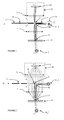
- the quasi-parallel shaping of the incident light beam for the illumination of a sample 10 can be carried out in the following manner.
- the light beam is derived from the illumination device 30_R. It is then focused, for example by a lens, on an inclined mirror 50, placed (in the detection column) a few millimeters from the optical axis YY and the focal plane FF, in this case higher, of the objective f1, that is to say near the focus point C of the objective f1.
- the mirror 50 may be a mirror of diameter 2 mm whose center is located 3 ⁇ 1 mm from the optical axis.
- the objective f1 transforms the beam into a quasi-parallel beam at the level of the sample 10.
- a semi-transparent mirror can be placed in the optical axis YY, also close to the focal plane FF of the lens f1, that is to say near the focus point C of the lens f1.
- the first arrangement requires working off-axis optical (more difficult settings, larger optical aberrations), but the second has the disadvantage of losing a factor T (1-T) on the collected intensity (where T is the transmission coefficient semi-transparent mirror), which is best avoided in fluorescence and Raman scattering.
- the optical axis, and therefore the optical column is vertical
- the light beam from the illumination device 30_R is horizontal
- the mirror 50 is inclined by approximately 45 ° (45 ° ⁇ 2 °).
- the inclined mirror 50 is the smallest possible (diameter of the order of 1 mm to a few mm), and the inclination of the beam relative to the optical axis is the lowest possible, given the need to prevent convergent C rays from intercepting said mirror 50.
- the light beam is derived from the illumination device 30_T. It is shaped quasi-parallel by unrepresented optical means and directed towards the sample from the rear, at near-normal incidence.
- the illumination device 30_R, 30_T may comprise a white light source (for example a xenon arc lamp, an arc or incandescent lamp) associated with a monochromator, or a source of light.
- white light source for example a xenon arc lamp, an arc or incandescent lamp
- monochromatic light light-emitting diode, laser diode or laser
- the quasi-parallel beam shaping can be done by injecting light from the source in a fiber or a bundle of optical fibers of moderate opening (advantageously less than or equal to 0.2) coupled to a lens.
- the uniformity of the illumination of the area to be explored is based on the homogeneity of the angular distribution.
- beam from the optical fiber Any nonuniformities may be corrected, either by a gradient filter or a suitable holographic filter interposed at the collimating lens, or by numerical correction at the level of the image analysis, these two correction techniques being equally applicable. to be combined.
- the parallel beam can be collimated to obtain illumination on a non-circular area, for example square or rectangular.
- light source in the sense of the present invention, is meant either a unit light source or a plurality of unit light sources, each unit source can emit on a common monochromatic wavelength or at a respective monochromatic wavelength.
- the objective f1 comprises a lens or assemblies of lenses, of focal length f1, providing at the detector 21 a magnification f2 / f1 of the order of 1 (advantageously between 0.1 and 10).
- the opening of said objective f1 is as large as possible (advantageously at least 1: 1.4).
- the objective f1 is configured to focus the exciter light beam downstream of the sample, at a point C located in the focal plane (in this case higher) FF of said objective f1 (which in the case of a single lens is located at the distance f1 above this lens).
- the objective f1 of large aperture allows, upstream of the sample to illuminate it in a quasi-parallel beam, of normal or near-normal incidence, and downstream of the sample, on the one hand to focus the beam reflected at the point C located in the focal plane of said objective, and secondly to transform the scattered beam into a quasi-parallel beam, so that it can be optionally detected by the optical detection device 20 at a wide angle solid (for example, for an aperture 1: 1.4, a half-angle at the apex of 20 ° and a solid angle of 0.12 ⁇ steradians).
- the beam resulting from the specular reflection is focused by the objective f1 at the point C downstream of the sample, while the scattered beam (reemitted by the sample) is not focused but is transformed into a quasi-parallel beam .
- the light beam is reflected by the sample with a wavelength identical to that of the incident beam.
- the light beam is re-emitted or scattered by the sample at a wavelength different from the incident wavelength (excluding Rayleigh scattering).
- a device 70 for selectively closing the collected light beam (by lens f1) is advantageously placed in the focal plane.
- This selective closure device 70 selectively enables the analysis of the sample according to at least two of the analysis techniques among the set comprising surface plasmon resonance, fluorescence, and Raman scattering, as described later.
- the device 70 for selectively closing the light beam may furthermore comprise at least one filter (no shown) from the set comprising a high-pass filter and a band-pass filter.
- the high-pass filter is used for the detection of fluorescence, and the band-pass filter for the detection of Raman scattering.
- the band-pass filter is a narrow band-pass filter, which makes it possible to obtain a good resolution in the determination of Raman shifts, and advantageously placed at the level of the shutter.
- This can be done by using a narrow-band interference filter.
- the bandwidth of the filter is less than or equal to 3 nm.
- the filter diameter 50 mm reference 03 FIL 008 marketed by Melles Griot which has a bandwidth of 1 nm centered on a wavelength of 632.8 nm, allows the measurement of Raman offsets with a resolution of 25 nm. cm -1 .
- a filter blocking the wavelength of the light used for the excitation;
- parasitic radiation due to the diffusion of the exciting light by the surface of the sample 10 or by the defects or dust of the optical system is prevented.
- optical filters For example, it is possible to increase the rejection ratio of a band-pass filter for certain blocked wavelengths by superimposing a high-pass filter and / or a low-pass filter on it, or by superimposing a low-pass filter. and a high-pass filter limit the detection band of the fluorescence to better guard against parasitic signals.
- the filter (s) is (are) coupled to said shutter 72, and possibly integral with the movement thereof.
- the shutter 72 it is possible for the shutter 72 to be rotatable and a set of at least one filter to be rotatable as well, possibly integrally with the movement of said shutter 72.
- the diaphragm 71 and the shutter 72 thus make it possible respectively to select the type of analysis technique from the set comprising surface plasmon resonance, fluorescence, and Raman scattering.
- the selective sealing of the light beam by the device 70 is implemented by switching between the diaphragm 71 and the shutter 72.
- the switching between the diaphragm 71 and the shutter 72 can be implemented by a mechanical switch, for example by rotational movement about an axis XX ( figure 1 ), preferably parallel to the optical axis YY, thanks to a pivoting disc. Or we can also provide a translational movement, preferably in a plane parallel to the focal plane FF, for example by a sliding zipper.
- the disk or the pull tab may also carry other optical functions (bright field imaging: wide diaphragm, dark field imaging: zone cache around point C, but no filter).
- Electrical switching may also be provided by a liquid crystal shutter device or an electrochromic device.
- the assembly comprising the device 70 for selectively closing the light beam and the mirror 50 (when it exists) is constructed in the form of a mechanically rigid block.
- the two sets (diaphragm 71 + possible filter and shutter 72 vs. inclined mirror 50) can not be located, exactly and simultaneously, in the focal plane FF of the lens f1.
- an offset of a few millimeters is tolerable, given the focal depth of the lens f1 and the diameter of the mirror 50, which can be slightly oversized.
- the illumination device 30 it is sufficient to adapt the illumination device 30 to select a length of light. particular wave of illumination of the sample 10.
- the illumination device 30 is capable of emitting a monochromatic light beam, variable or otherwise.
- the illumination device 30 may comprise an assembly of at least one optical fiber and an assembly of at least one unitary light source.
- At least one unit source is tunable, and / or that at least one unit source is a white source, the illumination device 30 then further comprising a monochromator.
- each fiber may be connected to a respective unit source, or the input of a single fiber is switched, shifted, from unit source to unit source.
- the single fiber is fixed and the unit sources are switched (displaced) at the input thereof.
- the switching of light source can be carried out either with movement by moving the end of an optical fiber (single fiber whose input is moved from one source to another, or fibers each connected to a respective source the output of one of them being chosen (selected) for the illumination of the sample 10); either without movement for example by variable wavelength source, or white source coupled to a monochromator.
- the transmitted light beam (reflected) by the sample 10 is blocked by the shutter 72 (preferably complementary to the diaphragm 71), the shutter 72 for filtering the focused portion of the beam output of the lens f1, so that only the non-focused portion of the light beam reaches the detection device 20.
- the shutter 72 preferably complementary to the diaphragm 71
- the shutter 72 for filtering the focused portion of the beam output of the lens f1, so that only the non-focused portion of the light beam reaches the detection device 20.
- the light is collected on a large solid angle by the detector.
- the present solution proposes instead to perform the detection of Raman scattering at a given wavelength, and to measure the Raman shifts by varying the excitation wavelength, which allows a Direct and simple comparison between LSPR, Raman and fluorescence images, and seems totally innovative.
- it is useful to be able to make such a comparison without processing the images, and having the ability to compare pixels with pixels having different contrasts and recorded by different techniques.
- the light source is monochromatic and tunable, so as to be able to measure different Raman offsets by choosing different wavelengths for the excitation.
- Raman images are recorded directly corresponding to the light scattered at the wavelength ⁇ _det selected by the narrow filter used for the detection, for an excitation wavelength from the light source ⁇ _exc.
- the principle retained has the further advantage of avoiding any parasitic contribution due to the Rayleigh scattering of the sample 10 or of the optical system.
- lasers or laser diodes are used in preference to electroluminescent diodes.
- a source for example a titanium-type laser: sapphire, possibly equipped with a frequency doubling system according to the desired wavelength range for the excitation), or a source based on on an optical parametric oscillator (OPO).
- a tunable solid laser for example a titanium-type laser: sapphire, possibly equipped with a frequency doubling system according to the desired wavelength range for the excitation
- OPO optical parametric oscillator
- These sources can be continuous or pulse light sources.
- a pulsed source it is advantageous to have a pulse duration greater than or equal to 100 fs so as to maintain the monochromatic nature of the source, and the highest possible repetition rate.
- OPO-based commercial sources can be used that provide illumination in the form of pulses of a few ns carrying a few tens of mJ with a repetition rate of 10 Hz or more; such sources provide high instantaneous powers favorable to observing the Raman effect.
- this filter can be a holographic filter with high rejection power.
- the 53684 reference filter marketed by Oriel attenuates the intensity of the radiation at 632.8 nm by a factor of greater than 10 ⁇ 6, with a blocking bandwidth of 28 nm, and makes it possible to detect higher Raman shifts. at 350 cm -1 .
- this filter being used in transmission on the excitation, it may be advantageous to use lower blocking power filters but having an excellent out-of-band blocking transmission so as to have a system more resistant to high current intensities.
- the B46-566 B46-566 Continuous Index Multilayer Filter marketed by Edmund Optics attenuates the intensity of the radiation at 632.8 nm by a factor greater than 10 ⁇ 3, with a slightly lower blocking bandwidth. less than 32 nm, which makes it possible to detect Raman shifts greater than 400 cm -1 . Given their high transmission outside the locking band, it is possible to use two or more of these filters in series to increase the rejection power.
- the rejection filter is advantageously arranged at the output of the source.
- the system can also keep the basic imaging function (bright field / dark field) by adding an additional set of diaphragms. It allows the realization of tests in air or in contact with a liquid medium and in real time to perform kinetic measurements.
- the coupling of the different techniques within the same tests makes it possible to obtain chemical or biochemical information with or without marking the targets or probes, to correlate the information obtained by at least two independent techniques and to carry out performance checks. real-time tests of the media used for the tests.
- the system can therefore implement a method of chemical, biological or biochemical analysis of a sample 10, in which said sample is illuminated with a monochromatic light beam; several images of said sample are acquired by switching between at least two of the analysis techniques among the set comprising surface plasmon resonance, fluorescence, and Raman scattering, and superimposing said images.
- the necessary spectral analysis is performed by recording several images corresponding to several excitation wavelengths.
- a tunable source may be advantageous.
- the invention it is possible to focus the transmitted or specularly reflected beam, so that it can either be selected by passing it through a diaphragm (reflectance / transmittance) or masked by a shutter (fluorescence, diffusion Raman), while maintaining the possibility of imaging the studied surface.
- a diaphragm reflectance / transmittance
- a shutter fluorescence, diffusion Raman
- no dispersive analysis device or spatial filtering device is used for the Raman analysis on the detection system; on the contrary, only the light emitted in a narrow band of wavelengths selected by a filter is detected.
- the invention is not limited to the embodiments described above. It can be applied in other contexts.
- These coded particles can be produced in large numbers at low cost with more than 10 6 distinct codes.
- These codes are read by measuring the reflectivity spectrum of the particle.
- the same probe is grafted onto all the particles of the same code, and then all the particles are put in contact with a sample to be analyzed containing targets marked with a fluorophore.
- the particles are then dispersed (by deposition and then evaporation) on the surface of a microscope slide, and molecular recognition is analyzed by measuring, under optical microscope, for each particle, its reflectivity spectrum and its fluorescence.
Landscapes
- Physics & Mathematics (AREA)
- Chemical & Material Sciences (AREA)
- General Physics & Mathematics (AREA)
- Analytical Chemistry (AREA)
- Health & Medical Sciences (AREA)
- Pathology (AREA)
- Life Sciences & Earth Sciences (AREA)
- Biochemistry (AREA)
- General Health & Medical Sciences (AREA)
- Immunology (AREA)
- Optics & Photonics (AREA)
- Nuclear Medicine, Radiotherapy & Molecular Imaging (AREA)
- Engineering & Computer Science (AREA)
- Nanotechnology (AREA)
- Mathematical Physics (AREA)
- Theoretical Computer Science (AREA)
- Spectroscopy & Molecular Physics (AREA)
- Investigating, Analyzing Materials By Fluorescence Or Luminescence (AREA)
- Investigating Or Analysing Materials By Optical Means (AREA)
Applications Claiming Priority (2)
| Application Number | Priority Date | Filing Date | Title |
|---|---|---|---|
| FR1060195A FR2968402B1 (fr) | 2010-12-07 | 2010-12-07 | Systeme et procede d'imagerie multitechniques pour l'analyse chimique, biologique ou biochimique d'un echantillon. |
| PCT/FR2011/052886 WO2012076810A1 (fr) | 2010-12-07 | 2011-12-07 | Systeme et procede d'imagerie multitechniques pour l'analyse chimique, biologique ou biochiimique d'un echantillon. |
Publications (2)
| Publication Number | Publication Date |
|---|---|
| EP2649431A1 EP2649431A1 (fr) | 2013-10-16 |
| EP2649431B1 true EP2649431B1 (fr) | 2015-03-04 |
Family
ID=44169104
Family Applications (1)
| Application Number | Title | Priority Date | Filing Date |
|---|---|---|---|
| EP11805108.5A Not-in-force EP2649431B1 (fr) | 2010-12-07 | 2011-12-07 | Systeme et procede d'imagerie multitechniques pour l'analyse chimique, biologique ou biochiimique d'un echantillon. |
Country Status (5)
| Country | Link |
|---|---|
| US (1) | US9476827B2 (enExample) |
| EP (1) | EP2649431B1 (enExample) |
| JP (1) | JP5985502B2 (enExample) |
| FR (1) | FR2968402B1 (enExample) |
| WO (1) | WO2012076810A1 (enExample) |
Families Citing this family (7)
| Publication number | Priority date | Publication date | Assignee | Title |
|---|---|---|---|---|
| JP6488501B2 (ja) * | 2013-09-11 | 2019-03-27 | 株式会社分光科学研究所 | 計測方法及び計測装置 |
| WO2016120757A1 (en) * | 2015-01-27 | 2016-08-04 | Ecole Polytechnique Federale De Lausanne (Epfl) | Observation device with optical compensation |
| US10705022B2 (en) | 2016-08-24 | 2020-07-07 | Goodrich Corporation | Robust spectroscopy systems |
| FR3058521B1 (fr) * | 2016-11-08 | 2021-01-08 | Univ Montpellier | Dispositif et procede de detection de presence de molecules determinees, biocapteur |
| CN106896095B (zh) * | 2017-01-11 | 2019-08-06 | 四川大学 | 复合表面等离子体共振及表面增强拉曼的显微成像技术 |
| WO2020235142A1 (ja) * | 2019-05-20 | 2020-11-26 | 日本電気株式会社 | 分光分析装置、分光分析方法及びコンピュータ可読媒体 |
| US12304278B2 (en) * | 2022-05-17 | 2025-05-20 | Ford Global Technologies, Llc | Air monitoring system for vehicle interior |
Family Cites Families (14)
| Publication number | Priority date | Publication date | Assignee | Title |
|---|---|---|---|---|
| US3229564A (en) * | 1961-05-12 | 1966-01-18 | Bausch & Lomb | Reflectometer |
| DE2402127C3 (de) * | 1974-01-17 | 1978-04-06 | Pluess-Staufer Ag, Oftringen (Schweiz) | Vorrichtung zur Messung des Glanzschleiers von Oberflächen |
| JPH1020203A (ja) * | 1996-07-08 | 1998-01-23 | Nikon Corp | 顕微鏡装置 |
| US5994707A (en) * | 1997-03-18 | 1999-11-30 | Physical Optics Corporation | Modular fiber optic fluorometer and method of use thereof |
| US6548796B1 (en) * | 1999-06-23 | 2003-04-15 | Regents Of The University Of Minnesota | Confocal macroscope |
| JP2001185796A (ja) * | 1999-12-27 | 2001-07-06 | Hitachi Metals Ltd | レーザ装置、その応用装置並びにその使用方法 |
| GB0106342D0 (en) * | 2001-03-15 | 2001-05-02 | Renishaw Plc | Spectroscopy apparatus and method |
| JP3741051B2 (ja) * | 2001-05-10 | 2006-02-01 | 横河電機株式会社 | バイオチップ読取装置 |
| JP4954452B2 (ja) * | 2004-07-06 | 2012-06-13 | オリンパス株式会社 | 顕微鏡 |
| DE102004034970A1 (de) * | 2004-07-16 | 2006-02-02 | Carl Zeiss Jena Gmbh | Lichtrastermikroskop und Verwendung |
| CN101031837B (zh) * | 2004-07-23 | 2011-06-15 | 通用电气医疗集团尼亚加拉有限公司 | 用于荧光共焦显微镜检查的方法和设备 |
| JP4520795B2 (ja) * | 2004-08-23 | 2010-08-11 | 株式会社ミツトヨ | 測定器 |
| WO2007070382A2 (en) * | 2005-12-09 | 2007-06-21 | Auburn University | Simultaneous observation of darkfield images and fluorescence using filter and diaphragm |
| US9234845B2 (en) * | 2006-10-19 | 2016-01-12 | Olympus Corporation | Microscope with reflecting fluorescence illumination optical system |
-
2010
- 2010-12-07 FR FR1060195A patent/FR2968402B1/fr not_active Expired - Fee Related
-
2011
- 2011-12-07 JP JP2013542590A patent/JP5985502B2/ja not_active Expired - Fee Related
- 2011-12-07 US US13/991,798 patent/US9476827B2/en not_active Expired - Fee Related
- 2011-12-07 EP EP11805108.5A patent/EP2649431B1/fr not_active Not-in-force
- 2011-12-07 WO PCT/FR2011/052886 patent/WO2012076810A1/fr not_active Ceased
Also Published As
| Publication number | Publication date |
|---|---|
| US20130314528A1 (en) | 2013-11-28 |
| FR2968402B1 (fr) | 2013-02-15 |
| EP2649431A1 (fr) | 2013-10-16 |
| WO2012076810A1 (fr) | 2012-06-14 |
| FR2968402A1 (fr) | 2012-06-08 |
| JP5985502B2 (ja) | 2016-09-06 |
| US9476827B2 (en) | 2016-10-25 |
| JP2013545989A (ja) | 2013-12-26 |
Similar Documents
| Publication | Publication Date | Title |
|---|---|---|
| EP2734884B1 (fr) | Dispositif optique d'éclairage conoscopique a cone creux pour microscope optique et procédé de microscopie optique en conoscopie | |
| EP2649431B1 (fr) | Systeme et procede d'imagerie multitechniques pour l'analyse chimique, biologique ou biochiimique d'un echantillon. | |
| EP3132237B9 (fr) | Appareil et procédé de microscopie à balayage de faisceau optique | |
| EP3069185B1 (fr) | Dispositif et methode de mise au point tridimensionnelle pour microscope | |
| EP3054281B1 (fr) | Dispositif de mesure d'un signal optique rétrodiffusé par un échantillon | |
| WO2020128333A1 (fr) | Appareil et procédé de micro-spectrométrie à balayage de faisceau lumineux | |
| FR2800163A1 (fr) | Dispositif de mesure de la repartition spatiale de l'emission spectrale d'un objet | |
| EP4078146B1 (fr) | Dispositif d'imagerie multi-spectrale infrarouge sans lentille et son procédé de fabrication | |
| FR2943428A1 (fr) | Dispositif de microscopie de fluorescence et methode d'observation associe | |
| WO2011027067A1 (fr) | Système de spectroscopie de fluorescence par corrélation temporelle pour l'analyse de particules dans un milieu | |
| EP2488854B1 (fr) | Procede et systeme d'imagerie par fonctionnalisation du substrat | |
| EP4548145A1 (fr) | Dispositif d'amplification d'un signal en imagerie de phase quantitative autoreferencee | |
| EP2877836A1 (fr) | Procedes optiques pour l'observation d'echantillons et pour la detection ou le dosage d'especes chimiques ou biologiques | |
| EP2021771B1 (fr) | Dispositif et procede de mesure permettant de caracteriser des surfaces par reflectometrie | |
| WO2024061843A1 (fr) | Microscope optique avec résonateur | |
| EP4305403A1 (fr) | Dispositif optique reflectometrique a balayage angulaire incline de surfaces cibles et procede de mesure associe | |
| FR2853072A1 (fr) | Dispositif de mesure de fluorescence d'une pluralite de zones a observer | |
| FR2860298A1 (fr) | Ellipsometre spectroscopique a polarisation incidente et analyseur fixes | |
| FR2819896A1 (fr) | Microscope confocal rapide |
Legal Events
| Date | Code | Title | Description |
|---|---|---|---|
| PUAI | Public reference made under article 153(3) epc to a published international application that has entered the european phase |
Free format text: ORIGINAL CODE: 0009012 |
|
| 17P | Request for examination filed |
Effective date: 20130528 |
|
| AK | Designated contracting states |
Kind code of ref document: A1 Designated state(s): AL AT BE BG CH CY CZ DE DK EE ES FI FR GB GR HR HU IE IS IT LI LT LU LV MC MK MT NL NO PL PT RO RS SE SI SK SM TR |
|
| DAX | Request for extension of the european patent (deleted) | ||
| GRAP | Despatch of communication of intention to grant a patent |
Free format text: ORIGINAL CODE: EPIDOSNIGR1 |
|
| INTG | Intention to grant announced |
Effective date: 20141125 |
|
| GRAS | Grant fee paid |
Free format text: ORIGINAL CODE: EPIDOSNIGR3 |
|
| GRAA | (expected) grant |
Free format text: ORIGINAL CODE: 0009210 |
|
| AK | Designated contracting states |
Kind code of ref document: B1 Designated state(s): AL AT BE BG CH CY CZ DE DK EE ES FI FR GB GR HR HU IE IS IT LI LT LU LV MC MK MT NL NO PL PT RO RS SE SI SK SM TR |
|
| REG | Reference to a national code |
Ref country code: GB Ref legal event code: FG4D Free format text: NOT ENGLISH |
|
| REG | Reference to a national code |
Ref country code: CH Ref legal event code: EP |
|
| REG | Reference to a national code |
Ref country code: IE Ref legal event code: FG4D Free format text: LANGUAGE OF EP DOCUMENT: FRENCH |
|
| REG | Reference to a national code |
Ref country code: AT Ref legal event code: REF Ref document number: 714297 Country of ref document: AT Kind code of ref document: T Effective date: 20150415 |
|
| REG | Reference to a national code |
Ref country code: DE Ref legal event code: R096 Ref document number: 602011014462 Country of ref document: DE Effective date: 20150416 |
|
| REG | Reference to a national code |
Ref country code: AT Ref legal event code: MK05 Ref document number: 714297 Country of ref document: AT Kind code of ref document: T Effective date: 20150304 Ref country code: NL Ref legal event code: VDEP Effective date: 20150304 |
|
| PG25 | Lapsed in a contracting state [announced via postgrant information from national office to epo] |
Ref country code: FI Free format text: LAPSE BECAUSE OF FAILURE TO SUBMIT A TRANSLATION OF THE DESCRIPTION OR TO PAY THE FEE WITHIN THE PRESCRIBED TIME-LIMIT Effective date: 20150304 Ref country code: LT Free format text: LAPSE BECAUSE OF FAILURE TO SUBMIT A TRANSLATION OF THE DESCRIPTION OR TO PAY THE FEE WITHIN THE PRESCRIBED TIME-LIMIT Effective date: 20150304 Ref country code: HR Free format text: LAPSE BECAUSE OF FAILURE TO SUBMIT A TRANSLATION OF THE DESCRIPTION OR TO PAY THE FEE WITHIN THE PRESCRIBED TIME-LIMIT Effective date: 20150304 Ref country code: ES Free format text: LAPSE BECAUSE OF FAILURE TO SUBMIT A TRANSLATION OF THE DESCRIPTION OR TO PAY THE FEE WITHIN THE PRESCRIBED TIME-LIMIT Effective date: 20150304 Ref country code: NO Free format text: LAPSE BECAUSE OF FAILURE TO SUBMIT A TRANSLATION OF THE DESCRIPTION OR TO PAY THE FEE WITHIN THE PRESCRIBED TIME-LIMIT Effective date: 20150604 Ref country code: SE Free format text: LAPSE BECAUSE OF FAILURE TO SUBMIT A TRANSLATION OF THE DESCRIPTION OR TO PAY THE FEE WITHIN THE PRESCRIBED TIME-LIMIT Effective date: 20150304 |
|
| REG | Reference to a national code |
Ref country code: LT Ref legal event code: MG4D |
|
| PG25 | Lapsed in a contracting state [announced via postgrant information from national office to epo] |
Ref country code: LV Free format text: LAPSE BECAUSE OF FAILURE TO SUBMIT A TRANSLATION OF THE DESCRIPTION OR TO PAY THE FEE WITHIN THE PRESCRIBED TIME-LIMIT Effective date: 20150304 Ref country code: AT Free format text: LAPSE BECAUSE OF FAILURE TO SUBMIT A TRANSLATION OF THE DESCRIPTION OR TO PAY THE FEE WITHIN THE PRESCRIBED TIME-LIMIT Effective date: 20150304 Ref country code: RS Free format text: LAPSE BECAUSE OF FAILURE TO SUBMIT A TRANSLATION OF THE DESCRIPTION OR TO PAY THE FEE WITHIN THE PRESCRIBED TIME-LIMIT Effective date: 20150304 |
|
| PG25 | Lapsed in a contracting state [announced via postgrant information from national office to epo] |
Ref country code: NL Free format text: LAPSE BECAUSE OF FAILURE TO SUBMIT A TRANSLATION OF THE DESCRIPTION OR TO PAY THE FEE WITHIN THE PRESCRIBED TIME-LIMIT Effective date: 20150304 |
|
| PG25 | Lapsed in a contracting state [announced via postgrant information from national office to epo] |
Ref country code: CZ Free format text: LAPSE BECAUSE OF FAILURE TO SUBMIT A TRANSLATION OF THE DESCRIPTION OR TO PAY THE FEE WITHIN THE PRESCRIBED TIME-LIMIT Effective date: 20150304 Ref country code: SK Free format text: LAPSE BECAUSE OF FAILURE TO SUBMIT A TRANSLATION OF THE DESCRIPTION OR TO PAY THE FEE WITHIN THE PRESCRIBED TIME-LIMIT Effective date: 20150304 Ref country code: EE Free format text: LAPSE BECAUSE OF FAILURE TO SUBMIT A TRANSLATION OF THE DESCRIPTION OR TO PAY THE FEE WITHIN THE PRESCRIBED TIME-LIMIT Effective date: 20150304 Ref country code: PT Free format text: LAPSE BECAUSE OF FAILURE TO SUBMIT A TRANSLATION OF THE DESCRIPTION OR TO PAY THE FEE WITHIN THE PRESCRIBED TIME-LIMIT Effective date: 20150706 Ref country code: RO Free format text: LAPSE BECAUSE OF FAILURE TO SUBMIT A TRANSLATION OF THE DESCRIPTION OR TO PAY THE FEE WITHIN THE PRESCRIBED TIME-LIMIT Effective date: 20150304 |
|
| REG | Reference to a national code |
Ref country code: FR Ref legal event code: PLFP Year of fee payment: 5 |
|
| PG25 | Lapsed in a contracting state [announced via postgrant information from national office to epo] |
Ref country code: PL Free format text: LAPSE BECAUSE OF FAILURE TO SUBMIT A TRANSLATION OF THE DESCRIPTION OR TO PAY THE FEE WITHIN THE PRESCRIBED TIME-LIMIT Effective date: 20150304 Ref country code: IS Free format text: LAPSE BECAUSE OF FAILURE TO SUBMIT A TRANSLATION OF THE DESCRIPTION OR TO PAY THE FEE WITHIN THE PRESCRIBED TIME-LIMIT Effective date: 20150704 |
|
| REG | Reference to a national code |
Ref country code: DE Ref legal event code: R097 Ref document number: 602011014462 Country of ref document: DE |
|
| PG25 | Lapsed in a contracting state [announced via postgrant information from national office to epo] |
Ref country code: IT Free format text: LAPSE BECAUSE OF FAILURE TO SUBMIT A TRANSLATION OF THE DESCRIPTION OR TO PAY THE FEE WITHIN THE PRESCRIBED TIME-LIMIT Effective date: 20150304 |
|
| PLBE | No opposition filed within time limit |
Free format text: ORIGINAL CODE: 0009261 |
|
| STAA | Information on the status of an ep patent application or granted ep patent |
Free format text: STATUS: NO OPPOSITION FILED WITHIN TIME LIMIT |
|
| PG25 | Lapsed in a contracting state [announced via postgrant information from national office to epo] |
Ref country code: DK Free format text: LAPSE BECAUSE OF FAILURE TO SUBMIT A TRANSLATION OF THE DESCRIPTION OR TO PAY THE FEE WITHIN THE PRESCRIBED TIME-LIMIT Effective date: 20150304 |
|
| 26N | No opposition filed |
Effective date: 20151207 |
|
| PG25 | Lapsed in a contracting state [announced via postgrant information from national office to epo] |
Ref country code: SI Free format text: LAPSE BECAUSE OF FAILURE TO SUBMIT A TRANSLATION OF THE DESCRIPTION OR TO PAY THE FEE WITHIN THE PRESCRIBED TIME-LIMIT Effective date: 20150304 |
|
| PG25 | Lapsed in a contracting state [announced via postgrant information from national office to epo] |
Ref country code: BE Free format text: LAPSE BECAUSE OF NON-PAYMENT OF DUE FEES Effective date: 20151231 |
|
| PG25 | Lapsed in a contracting state [announced via postgrant information from national office to epo] |
Ref country code: MC Free format text: LAPSE BECAUSE OF FAILURE TO SUBMIT A TRANSLATION OF THE DESCRIPTION OR TO PAY THE FEE WITHIN THE PRESCRIBED TIME-LIMIT Effective date: 20150304 Ref country code: LU Free format text: LAPSE BECAUSE OF FAILURE TO SUBMIT A TRANSLATION OF THE DESCRIPTION OR TO PAY THE FEE WITHIN THE PRESCRIBED TIME-LIMIT Effective date: 20151207 |
|
| REG | Reference to a national code |
Ref country code: CH Ref legal event code: PL |
|
| REG | Reference to a national code |
Ref country code: IE Ref legal event code: MM4A |
|
| REG | Reference to a national code |
Ref country code: FR Ref legal event code: PLFP Year of fee payment: 6 |
|
| PG25 | Lapsed in a contracting state [announced via postgrant information from national office to epo] |
Ref country code: IE Free format text: LAPSE BECAUSE OF NON-PAYMENT OF DUE FEES Effective date: 20151207 Ref country code: CH Free format text: LAPSE BECAUSE OF NON-PAYMENT OF DUE FEES Effective date: 20151231 Ref country code: LI Free format text: LAPSE BECAUSE OF NON-PAYMENT OF DUE FEES Effective date: 20151231 |
|
| PG25 | Lapsed in a contracting state [announced via postgrant information from national office to epo] |
Ref country code: HU Free format text: LAPSE BECAUSE OF FAILURE TO SUBMIT A TRANSLATION OF THE DESCRIPTION OR TO PAY THE FEE WITHIN THE PRESCRIBED TIME-LIMIT; INVALID AB INITIO Effective date: 20111207 Ref country code: BG Free format text: LAPSE BECAUSE OF FAILURE TO SUBMIT A TRANSLATION OF THE DESCRIPTION OR TO PAY THE FEE WITHIN THE PRESCRIBED TIME-LIMIT Effective date: 20150304 Ref country code: SM Free format text: LAPSE BECAUSE OF FAILURE TO SUBMIT A TRANSLATION OF THE DESCRIPTION OR TO PAY THE FEE WITHIN THE PRESCRIBED TIME-LIMIT Effective date: 20150304 |
|
| PG25 | Lapsed in a contracting state [announced via postgrant information from national office to epo] |
Ref country code: CY Free format text: LAPSE BECAUSE OF FAILURE TO SUBMIT A TRANSLATION OF THE DESCRIPTION OR TO PAY THE FEE WITHIN THE PRESCRIBED TIME-LIMIT Effective date: 20150304 Ref country code: GR Free format text: LAPSE BECAUSE OF FAILURE TO SUBMIT A TRANSLATION OF THE DESCRIPTION OR TO PAY THE FEE WITHIN THE PRESCRIBED TIME-LIMIT Effective date: 20150304 |
|
| PG25 | Lapsed in a contracting state [announced via postgrant information from national office to epo] |
Ref country code: MT Free format text: LAPSE BECAUSE OF FAILURE TO SUBMIT A TRANSLATION OF THE DESCRIPTION OR TO PAY THE FEE WITHIN THE PRESCRIBED TIME-LIMIT Effective date: 20150304 |
|
| REG | Reference to a national code |
Ref country code: FR Ref legal event code: PLFP Year of fee payment: 7 |
|
| PG25 | Lapsed in a contracting state [announced via postgrant information from national office to epo] |
Ref country code: MK Free format text: LAPSE BECAUSE OF FAILURE TO SUBMIT A TRANSLATION OF THE DESCRIPTION OR TO PAY THE FEE WITHIN THE PRESCRIBED TIME-LIMIT Effective date: 20150304 Ref country code: TR Free format text: LAPSE BECAUSE OF FAILURE TO SUBMIT A TRANSLATION OF THE DESCRIPTION OR TO PAY THE FEE WITHIN THE PRESCRIBED TIME-LIMIT Effective date: 20150304 |
|
| REG | Reference to a national code |
Ref country code: FR Ref legal event code: PLFP Year of fee payment: 8 |
|
| PG25 | Lapsed in a contracting state [announced via postgrant information from national office to epo] |
Ref country code: AL Free format text: LAPSE BECAUSE OF FAILURE TO SUBMIT A TRANSLATION OF THE DESCRIPTION OR TO PAY THE FEE WITHIN THE PRESCRIBED TIME-LIMIT Effective date: 20150304 |
|
| PGFP | Annual fee paid to national office [announced via postgrant information from national office to epo] |
Ref country code: DE Payment date: 20191210 Year of fee payment: 9 |
|
| PGFP | Annual fee paid to national office [announced via postgrant information from national office to epo] |
Ref country code: FR Payment date: 20191017 Year of fee payment: 9 |
|
| PGFP | Annual fee paid to national office [announced via postgrant information from national office to epo] |
Ref country code: GB Payment date: 20191220 Year of fee payment: 9 |
|
| REG | Reference to a national code |
Ref country code: DE Ref legal event code: R119 Ref document number: 602011014462 Country of ref document: DE |
|
| GBPC | Gb: european patent ceased through non-payment of renewal fee |
Effective date: 20201207 |
|
| PG25 | Lapsed in a contracting state [announced via postgrant information from national office to epo] |
Ref country code: FR Free format text: LAPSE BECAUSE OF NON-PAYMENT OF DUE FEES Effective date: 20201231 |
|
| PG25 | Lapsed in a contracting state [announced via postgrant information from national office to epo] |
Ref country code: DE Free format text: LAPSE BECAUSE OF NON-PAYMENT OF DUE FEES Effective date: 20210701 Ref country code: GB Free format text: LAPSE BECAUSE OF NON-PAYMENT OF DUE FEES Effective date: 20201207 |