EP2643522B1 - Brückenvorrichtung - Google Patents
Brückenvorrichtung Download PDFInfo
- Publication number
- EP2643522B1 EP2643522B1 EP11805565.6A EP11805565A EP2643522B1 EP 2643522 B1 EP2643522 B1 EP 2643522B1 EP 11805565 A EP11805565 A EP 11805565A EP 2643522 B1 EP2643522 B1 EP 2643522B1
- Authority
- EP
- European Patent Office
- Prior art keywords
- platform
- bridge apparatus
- bridge
- capstan
- movement
- Prior art date
- Legal status (The legal status is an assumption and is not a legal conclusion. Google has not performed a legal analysis and makes no representation as to the accuracy of the status listed.)
- Not-in-force
Links
- 230000033001 locomotion Effects 0.000 claims description 70
- 230000007246 mechanism Effects 0.000 claims description 36
- 230000001133 acceleration Effects 0.000 claims description 10
- NJPPVKZQTLUDBO-UHFFFAOYSA-N novaluron Chemical compound C1=C(Cl)C(OC(F)(F)C(OC(F)(F)F)F)=CC=C1NC(=O)NC(=O)C1=C(F)C=CC=C1F NJPPVKZQTLUDBO-UHFFFAOYSA-N 0.000 claims description 9
- 238000000034 method Methods 0.000 claims description 4
- XLYOFNOQVPJJNP-UHFFFAOYSA-N water Substances O XLYOFNOQVPJJNP-UHFFFAOYSA-N 0.000 claims description 4
- 230000009471 action Effects 0.000 claims description 2
- 238000009434 installation Methods 0.000 description 42
- 230000008901 benefit Effects 0.000 description 8
- 230000004044 response Effects 0.000 description 7
- 230000000007 visual effect Effects 0.000 description 5
- 230000004888 barrier function Effects 0.000 description 3
- 238000012544 monitoring process Methods 0.000 description 3
- 238000012546 transfer Methods 0.000 description 3
- 230000004913 activation Effects 0.000 description 1
- 238000013459 approach Methods 0.000 description 1
- 230000009194 climbing Effects 0.000 description 1
- 238000013461 design Methods 0.000 description 1
- 230000000694 effects Effects 0.000 description 1
- 238000005516 engineering process Methods 0.000 description 1
- 230000006870 function Effects 0.000 description 1
- 230000006872 improvement Effects 0.000 description 1
- 238000012423 maintenance Methods 0.000 description 1
- 238000012986 modification Methods 0.000 description 1
- 230000004048 modification Effects 0.000 description 1
- 230000003287 optical effect Effects 0.000 description 1
- 239000011295 pitch Substances 0.000 description 1
- 230000008439 repair process Effects 0.000 description 1
- 238000005096 rolling process Methods 0.000 description 1
- 239000007787 solid Substances 0.000 description 1
Images


Classifications
-
- B—PERFORMING OPERATIONS; TRANSPORTING
- B63—SHIPS OR OTHER WATERBORNE VESSELS; RELATED EQUIPMENT
- B63B—SHIPS OR OTHER WATERBORNE VESSELS; EQUIPMENT FOR SHIPPING
- B63B27/00—Arrangement of ship-based loading or unloading equipment for cargo or passengers
- B63B27/14—Arrangement of ship-based loading or unloading equipment for cargo or passengers of ramps, gangways or outboard ladders ; Pilot lifts
-
- B—PERFORMING OPERATIONS; TRANSPORTING
- B63—SHIPS OR OTHER WATERBORNE VESSELS; RELATED EQUIPMENT
- B63B—SHIPS OR OTHER WATERBORNE VESSELS; EQUIPMENT FOR SHIPPING
- B63B27/00—Arrangement of ship-based loading or unloading equipment for cargo or passengers
- B63B27/30—Arrangement of ship-based loading or unloading equipment for transfer at sea between ships or between ships and off-shore structures
-
- E—FIXED CONSTRUCTIONS
- E01—CONSTRUCTION OF ROADS, RAILWAYS, OR BRIDGES
- E01D—CONSTRUCTION OF BRIDGES, ELEVATED ROADWAYS OR VIADUCTS; ASSEMBLY OF BRIDGES
- E01D15/00—Movable or portable bridges; Floating bridges
- E01D15/06—Bascule bridges; Roller bascule bridges, e.g. of Scherzer type
-
- E—FIXED CONSTRUCTIONS
- E01—CONSTRUCTION OF ROADS, RAILWAYS, OR BRIDGES
- E01D—CONSTRUCTION OF BRIDGES, ELEVATED ROADWAYS OR VIADUCTS; ASSEMBLY OF BRIDGES
- E01D15/00—Movable or portable bridges; Floating bridges
- E01D15/06—Bascule bridges; Roller bascule bridges, e.g. of Scherzer type
- E01D15/08—Drawbridges
-
- E—FIXED CONSTRUCTIONS
- E01—CONSTRUCTION OF ROADS, RAILWAYS, OR BRIDGES
- E01D—CONSTRUCTION OF BRIDGES, ELEVATED ROADWAYS OR VIADUCTS; ASSEMBLY OF BRIDGES
- E01D15/00—Movable or portable bridges; Floating bridges
- E01D15/12—Portable or sectional bridges
- E01D15/124—Folding or telescopic bridges; Bridges built up from folding or telescopic sections
-
- E—FIXED CONSTRUCTIONS
- E01—CONSTRUCTION OF ROADS, RAILWAYS, OR BRIDGES
- E01D—CONSTRUCTION OF BRIDGES, ELEVATED ROADWAYS OR VIADUCTS; ASSEMBLY OF BRIDGES
- E01D15/00—Movable or portable bridges; Floating bridges
- E01D15/24—Bridges or similar structures, based on land or on a fixed structure and designed to give access to ships or other floating structures
-
- B—PERFORMING OPERATIONS; TRANSPORTING
- B63—SHIPS OR OTHER WATERBORNE VESSELS; RELATED EQUIPMENT
- B63B—SHIPS OR OTHER WATERBORNE VESSELS; EQUIPMENT FOR SHIPPING
- B63B17/00—Vessels parts, details, or accessories, not otherwise provided for
- B63B2017/0072—Seaway compensators
-
- B—PERFORMING OPERATIONS; TRANSPORTING
- B63—SHIPS OR OTHER WATERBORNE VESSELS; RELATED EQUIPMENT
- B63B—SHIPS OR OTHER WATERBORNE VESSELS; EQUIPMENT FOR SHIPPING
- B63B27/00—Arrangement of ship-based loading or unloading equipment for cargo or passengers
- B63B27/14—Arrangement of ship-based loading or unloading equipment for cargo or passengers of ramps, gangways or outboard ladders ; Pilot lifts
- B63B2027/141—Arrangement of ship-based loading or unloading equipment for cargo or passengers of ramps, gangways or outboard ladders ; Pilot lifts telescopically extendable
Definitions
- This invention relates to a bridge apparatus to transfer persons between a moving structure such as a vessel and a second structure such as an offshore installation.
- Embodiments of the invention are particularly useful to span gaps between work boats and fixed offshore installations such as wind turbines.
- bridge apparatus according to claim 1.
- the platform apparatus is provided on a floating support structure such as a water craft or vessel, it can be configured to move vertically (e.g. pivoting around a horizontal axis on the vessel) in contra-response to the movement of the vessel in water and so reduce at least in the vertical plane, and can typically eliminate, the relative vertical movement between at least a part of the platform and an installation/work platform, such as an offshore wind turbine, which can be fixed to the sea bed.
- an installation/work platform such as an offshore wind turbine
- the inboard end of the bridge apparatus can remain in generally the same vertical position in relation to the support structure of the vessel, moving with the vessel in the water, and the outboard end of the bridge apparatus can remain in generally the same vertical position relative to the second structure/installation of the wind turbine (but need not necessarily be secured to the wind turbine) and the relative vertical movement between the support structure and the second structure is compensated for by the movement of the bridge.
- the outboard end that extends toward the installation remains relatively vertically stationary in relation to the stationary installation
- the inboard end that is connected to the support structure of the vessel moves with the vessel relative to the installation, but relative to the vessel it remains in generally the same relative vertical position. Therefore, relative vertical movement is accommodated by movement of the bridge in between the support structure and the installation, while the stepping on and stepping off points on the bridge remain generally still in relation to the vessel and the wind turbine.
- the bridge apparatus can be pivotally connected to the vessel, and can be pivotally connected or otherwise engaged with the installation (e.g. the wind turbine).
- the bridge apparatus can typically pivot around more than one axis, typically two axes, for example, in vertical and horizontal planes.
- the pivot axes can typically be at least capable of allowing pivotal movement of the bridge in the vertical plane, so that for example, with a bridge attached between the side of a rolling vessel and a stationary wind turbine, the bridge moves up and down in the vertical plane around a pivot axis that is horizontal and parallel to the bow-stern axis of the vessel as the vessel rolls from side to side relative to the stationary wind turbine.
- the pivot axes can also typically be capable of allowing pivotal movement of the bridge in the horizontal plane, so that for example, with a bridge attached between the side of a vessel and a wind turbine, the bridge moves laterally from side to side in the horizontal plane around a pivot axis that is vertical, as the vessel pitches from bow to stern relative to the stationary wind turbine.
- the movement of the bridge in such circumstances is typically a combination of movement around the vertical and horizontal axes of the connection.
- a counterweight as described herein can reduce the range of stress provided on control systems or the like, and so can save energy in operating the bridge apparatus, and can require lighter and less powerful control systems.
- the counterweight is set to be slightly less than the weight of the platform, for example 70-95% of the platform weight, typically 80-95% of the platform weight, and typically around 90% of the platform weight.
- the bridge motion is typically compensated against the dynamic motions of the vessel by monitoring and measuring the vessel accelerations. This can be done optionally by accelerometers, and typically accelerometers measuring accelerations in 3 axes.
- the acceleration data are optionally collated by a Motion Reference Unit (MRU).
- MRU Motion Reference Unit
- the MRU typically feeds the data to a programmable logic controller which is typically programmed to calculate the necessary capstan winch motor speed to match and accommodate the accelerations of the vessel.
- the bridge position (or at least the outboard end of the bridge) is kept in a relatively constant position relative to the fixed installation, irrespective of the motion of the vessel, which helps the operator to use the control system to safely guide the bridge onto the landing point on the fixed installation.
- the drivers for the active movement of the platform relative to the vessel are powered down (optionally switched off, but can be operated at lower power in some embodiments) and the bridge moves passively relative to the vessel to which it is attached.
- the counterweight is set to around 85%-95%, e.g. 90% of the bridge mass
- the bridge has a nose weight on the landing point of the installation of around 10% of its mass.
- the active drives are now typically in bypass mode the bridge moves with the motion of the vessel, and the light nose weight of around 10% of the bridge mass keeps the bridge in position on the landing point on the installation, but typically the light nose weight is not sufficient to rigidly attach the bridge to the landing point with any significant force.
- the system can typically alarm and can be set to withdraw the bridge safely and resume active mode.
- the bridge apparatus may be provided on a stationary or moving installation such as a stationary or moving offshore wind turbine, pillar, support structure or the like for connection to a second structure. Normally either the installation or the second structure moves in use.
- a vessel comprising the bridge apparatus as described herein.
- the vessel may be a SWATH type vessel, for example a 60m SWATH supplied by Abeking & Rasmussen (Lemwerder, Germany) although other vessels may be used.
- the platform apparatus extends outwards from the vessel.
- An angle is defined between the vessel and the bridge apparatus.
- the platform apparatus is normally partially laterally rotatable in the horizontal plane, such that, starting at the position where the bridge apparatus extends outwards from the side of the vessel so that it is perpendicular to the bow-stern axis of the vessel (0°) it can move by at least 10°, typically at least 20°, optionally at least 30°, and in some embodiments more than 35° around a vertical axis. Normally such rotation is provided in both lateral directions.
- Such movement of the platform apparatus allows the bridge apparatus to counteract rotation around a vertical axis, pitching around a horizontal axis and fore-aft movement of the vessel relative to the installation in order to reduce, and typically eliminate, relative movement between the bridge and the installation.
- the platform apparatus has an axis and is extendable along the axis, such that it may extend and retract in length. Thus in use on a vessel it may be extended towards or retracted away from the installation. Such embodiments allow the platform apparatus to be extended to contact the installation. Typically a telescopic mechanism is provided to allow the platform apparatus to extend and retract. Thus the bridge apparatus can use such movement to extend and retract the platform apparatus, and also to cope with unintended lateral movement of the vessel relative to the installation, caused by waves for example.
- the bridge apparatus can move through all three dimensions.
- the platform apparatus has all degrees of freedom to enable it to maintain a safe access platform for all expected relative vessel motions.
- Typical movement of the bridge apparatus in at least one, typically two, and optionally all three dimensions may be controlled by a motorised mechanism.
- the motorised mechanism to control the at least one line is a capstan mechanism.
- the capstan is provided on a pedestal, typically a head of the pedestal.
- the counterweight is provided behind and below the pedestal. This has the advantage that it keeps the structure light and reduces the loads on the capstan and capstan mechanism.
- the line can comprise a wire.
- the capstan may be a large diameter capstan, i.e. having a diameter of at least 30 times the line diameter to reduce friction and extend the life of the wire.
- a closed loop hydraulic drive to apply the required amount of torque to support the platform apparatus.
- the motorised mechanism to rotate the bridge comprises a slew gear rotation (ring gear and pinion drive, optionally in the pedestal)
- the motorised mechanism to control the extension of the telescopic platform apparatus comprises a section drive (twin rack and pinion).
- the bridge apparatus comprises an automated launching mechanism.
- the bridge apparatus comprises at least one, typically a combination of sensors.
- the sensors may include one or more of motion sensors, distance sensors, position sensors and visual sensors and are often provided on the far end of the platform apparatus.
- the sensors and launching mechanism are operable to maintain a position relative to a target on the installation.
- the sensors can combine optical and accelerometers to capture the relative motion.
- a feedback loop may be incorporated and software used to triangulate the positions.
- an operator can position the vessel next to the installation, and activate the automated launching system.
- the platform apparatus can then extend and move towards the installation, taking into account any relative movement between the vessel and the installation.
- the installation may be provided with an easily detectable target for the sensors to detect, to facilitate the automatic launching mechanism.
- the platform apparatus comprises a platform and typically also comprises a post and/or side barrier. Often the at least one line will be connected to the post and/or side barrier which is in turn connected to the platform.
- the at least one line will extend in part, horizontally as well as vertically to the capstan, i.e. it typically extends diagonally. Normally there are two lines, typically on each side of the platform apparatus.
- the platform apparatus normally extends for more than 5m, typically more than 8m and may extend for more than 10m.
- the motorised mechanisms controlling the movement of the bridge apparatus are adapted to operate in an active mode, where movement extension/retraction of the bridge apparatus can be effected, and a passive mode, where the movement extension/retraction of the bridge apparatus largely, typically exclusively, reacts to the relative movement of the vessel and installation.
- the motorised mechanisms are typically all put into a bypass mode whereby all motions react directly to the vessel motion and so typically no power is required.
- capstan and slew gear motors would go into bypass so the platform apparatus follows the motion of the vessel while maintaining contact with the installation.
- the motorised mechanism for the platform apparatus also functions in bypass mode.
- the bridge apparatus is fully active when being deployed and recovered to facilitate accurate alignment to an installation, but once engaged, reverts to passive mode to respond automatically to the relative motion between the vessel and the installation. In the passive mode, no power may be required.
- a bridge apparatus comprising a platform apparatus, the platform apparatus moveable in at least one dimension, wherein the platform apparatus is moved by action of a motorised mechanism, the motorised mechanism being operable between an active mode when it is operable to move the platform apparatus, and a passive mode when the power is reduced to the movement mechanism and it reacts more to movement caused in use than when in the active mode.
- the invention also provides a vessel comprising the bridge apparatus.
- the invention also provides a method of operating a bridge apparatus in accordance with claim 15.
- the first moving structure is a vessel.
- the bridge apparatus of the second aspect of the invention comprises all the features of the bridge apparatus according to the first aspect of the invention as defined in claim 1, and all optional features of the bridge apparatus according to the first aspect of the invention are also optional features according to the second aspect of the invention.
- the movement of the bridge apparatus in all three dimensions, as described for the first aspect of the invention is also an optional feature for embodiments according to the second aspect of the invention.
- the active mode is typically operated to move the platform apparatus in order to deploy and recover the platform apparatus and the passive mode is used when the platform apparatus is in place and stationary.
- an advantage of embodiments in accordance with the second aspect of the invention is that the bridge apparatus relies less on a computer controlled system to maintain connection between a vessel and an installation in use, and so such a robust software system to maintain contact is not required.
- the power to the motorised mechanisms is reduced by at least 50% in the passive mode compared to the active mode, typically at least 75%, more typically at least 90%.
- the motors controlling the movement in each direction are entirely passive and so the power to the motorised mechanisms is switched off.
- a main hydraulic unit is typically placed in a passive/standby mode.
- a control system typically interrogates sensors and if they are within safe pre-determined parameters the control system will typically shut down the main power supplies.
- a small make-up pump maintains a hydraulic system connected to the motorised mechanisms in a safe state to stop the likes of cavitation as the motorised mechanisms become pumps in effect. If the control system, which is typically monitoring at all times, detects any movement getting close to a pre-determined safety limit the main hydraulic power unit is typically powered up in readiness to make an automated detachment from the installation so as to prevent damage to either the bridge apparatus or the installation.
- control system and perhaps associated limit switches
- monitoring typically the extreme range of movements for all three degrees of movement, along with associated controls providing alarms and ultimately the emergency raising and retraction of the bridge, uses hardware/analogue systems typically by mechanical/electrical limit switches and relays. Typically therefore no software is included in these features.
- An advantage of such embodiments is that costs are kept low while achieving very high inherent safety and reliability.
- an alarm system is provided which will sound should the bridge apparatus extend beyond its range of motion.
- a series of graduated alarms may be provided.
- the bridge apparatus comprises a platform apparatus, the platform apparatus moveable in at least one dimension, the bridge apparatus having an alarm system adapted to trigger an alarm when the bridge apparatus is moved beyond a pre-determined position.
- bridge apparatus typically moves in all degrees of freedom to cope with all expected vessel motions. However should these be exceeded there may be a "traffic light" visual warning and/or audio warning system to alert the users.
- the bridge apparatus is typically adapted to automatically break free to prevent damage to the installation.
- the alarm may trigger activation of the motorised mechanisms on a stand by basis. Movement past further predetermined points may be adapted to cause more severe alarms or indeed automatic disengagement from the installation.
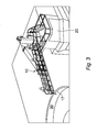
- Fig. 1 shows a side view of a bridge apparatus 10, connected to a vessel 20 and spanning a gap 22 above the sea 53 between the vessel 20 and a wind turbine support pillar (not shown in Fig. 1 ).
- the bridge apparatus 10 comprises two platforms 12a, 12b telescopically connected to one another, and two lines (or backstays) 14a, 14b supporting the platforms 12a, 12b via side barriers 16.
- the wires 14a, 14b extend in a diagonal (partly vertical, partly horizontal) direction from the platform 12a to a capstan 18 and onwards to a counterweight 19.
- the bridge apparatus 10 comprises a plurality of motorised mechanisms: an actuator 29 controls telescopic extension and retraction of the platform 12b toward and away from the platform 12a; a slew mechanism with a slew drive 21 and ring gear 23 rotates the platforms 12a, 12b laterally around a vertical axis relative to a pedestal 13; and a capstan drive motor 25 drives the capstan 18 in order to pivot the platform 12a around a horizontal axis at pivot point 27.
- a hydraulic power unit 50 is provided which comprises an electric motor 52 and a bi-directional pump 54 which controls the capstan drive motor 25. Hydraulic power is also supplied to the slew drive 21 and extension/retraction actuator 29.
- An invertor bi-directional speed drive 56 is connected to the hydraulic power unit 50.
- An operator control unit 57 is attached to this bi-directional speed drive 56 via a central control unit 58.
- Various sensors 33 are provided on the platform 12b so that the bridge apparatus 10 can automatically sense the platform's position during movement and can be directed to the desired position. The sensors 33 also receive hydraulic power from the hydraulic power unit 50.
- the vessel 20 is manoeuvred alongside the turbine support such that the bridge apparatus 10 is facing a landing point on the turbine support 30.
- the actuator 29 extends the platform 12b telescopically outwards from the platform 12a so that, after such extension, the platform 12a, 12b on the side of the vessel 10 extends towards the turbine support.
- the bridge apparatus 10 thereby spans the gap 22 between the vessel 20 and the turbine support 30, as shown in Fig. 3 .
- the platforms 12a, 12b may be rotated or pivoted by the slew mechanism 21, 23 and capstan 18 respectively in order to reach this landed position.
- the telescopic platform 12a, 12b locks to the turbine support 30 by a rollered V-saddle 15 which sits on a 150mm diameter top rail 17 which surrounds the entire turbine support 30.
- a rail 17 can be readily retro-fitted to existing turbine supports.
- An automatic guidance mechanism comprises the sensors 33.
- Established position sensing and hydraulic control technology may be used for the guidance mechanism. These may include magnetic/proximity sensors, visual IR sensors, laser sensors, and/or solid state inertia accelerometers. Such sensors are commercially available from various companies, such as Siemens (Surrey, UK and international), Schneider, Omron and Emerson.
- this may be performed by manual control systems.
- the movement to span the gap 22 can be automatic once directed by a controller; the sensors 33 recognising a target position and software compensating for movement of the vessel in any direction.
- the various motorised mechanisms are then powered down and the platforms 12a, 12b allowed, within a certain range of motion described below, to pivot, rotate and extend/retract in response to the movement of the vessel relative to the turbine support 30.
- the platforms 12a, 12b are adapted to move in response to the relative movement of the vessel 20 and turbine support 30, such embodiments of the present invention do not require complex software to align and maintain the platforms 12a, 12b in place. Rather the motors are powered down so the platforms 12a, 12b reacts and moves according to the movement of the vessel 20.
- the illustrated embodiment can pivot with a vertical angle of the bridge apparatus as 18 ° above and below the horizontal. Between 18 and 23 ° the bridge apparatus may be operated with care, whilst beyond 23 ° it will disengage from the turbine support 30 so to prevent damage to the bridge apparatus 10 or the turbine support 30.
- the various motorised mechanisms are adapted to power up when the platforms 12a, 12b reach a pre-determined angle in any dimension such as an angle of above 26.5 ° (or whatever angle is allowable for that particular embodiment) in order to be ready to be activated to disengage the platforms 12a, 12b from the turbine support where the angle caused by movement of the vessel is too large for the allowable range of motion for the platforms 12a, 12b.
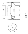
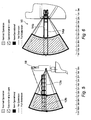
- Fig. 6 illustrates the rotation that the platforms 12a, 12b may undergo to gain access to the turbine support 30, and more importantly, in response to the movement of the vessel 20.
- it may rotate by up to 27.25 ° in normal operation in either direction. Above 27.25 ° and less than 32.25 ° operation with care is permitted.
- the capstan motor 25, slew drive 21 and actuator 29 will power up to be on stand-by should the platforms 12a, 12b require to be disengaged quickly if further limits are also exceeded. Beyond 32.25 ° the motorised mechanisms will engage to disconnect the platforms 12a, 12b from the turbine platform 30.
- proximity sensors in the telescopic platform section and pedestal slew gear continuously monitor their positions and if either approach the pre determined limits an amber visual alarm is given to warn any users on the platforms 12a, 12b that the movement capacity is being reached. If the range of motions reaches a further predetermined limit indicative of a dangerous level then a red visual and audio alarm sound and the platforms 12a, 12b will be raised by the wires 14a, 14b and the telescopic platform 12a, 12b retracted to avoid damage to the platforms 12a, 12b or the turbine support 30.
- embodiments of the invention also provide the ability to directly access the turbine support without stepping across from a moving boat and climbing a ladder. Moreover certain embodiments allow such a transfer to take place in sea states of 3mHs and higher.
- embodiments of the invention provide a motion compensated personnel access bridge apparatus to enable personnel to move directly from a support vessel to a tower work platform typically at 20m above Lowest Astronomical Tide (LAT) in high sea states.
- LAT Lowest Astronomical Tide
- embodiments of the invention benefit in that they provide a light weight, low power and inherently safe design.
- embodiments of the invention benefit in that the active phase is limited to the unmanned deployment and retrieval which reduces the criticality and cost of the software and componentry.
- Embodiments of the invention benefit in that referencing is by local radar sensors which determine the relative position of the end of the telescopic platforms 12a, 12b section to a target ring integrated into the turbine support.
- low cost accelerometers can also detect the absolute accelerations for back up and cross reference.
- embodiments of the invention benefit in that the platforms are counterbalanced by passing a support line around a capstan at the head of a support pedestal before going to a back tension counterweight.
- One benefit in counterbalancing the platforms is that it markedly reduces the power demand on a motion control system, which aside from reducing cost, weight, energy demand and wear, enables a very fast response control system which is largely immune from the vertical acceleration component as it acts equally on the bridge apparatus mass and counterweight. Due to the counterbalance, the required amount of torque to support the platforms is far lower and less variable which aids response and keeps the power very low.
- the counterbalance also ensures the landing weight of the bridge apparatus on the turbine support is at an acceptably low level. Embodiments of the invention can help to allow safer transfer of personnel from a vessel to an offshore turbine installation or other such offshore structure.
Landscapes
- Engineering & Computer Science (AREA)
- Architecture (AREA)
- Civil Engineering (AREA)
- Structural Engineering (AREA)
- Chemical & Material Sciences (AREA)
- Combustion & Propulsion (AREA)
- Mechanical Engineering (AREA)
- Ocean & Marine Engineering (AREA)
- Bridges Or Land Bridges (AREA)
Claims (15)
- Brückenvorrichtung (10), montiert auf einer Stützkonstruktion (20) und konfiguriert, um eine Lücke zwischen der Stützkonstruktion und einer zweiten Konstruktion (30) zu überspannen, wobei die Brückenvorrichtung (10) eine Plattform (120, gestützt durch mindestens ein Seil (14), beinhaltet;
wobei mindestens ein Abschnitt der Plattform (12) durch Bewegung des mindestens einen Seils (14) in einer Vertikalebene bewegbar ist;
wobei sich das mindestens eine Seil (14) von der Plattform (12) zu einem Spill (18), das über der Plattform (12) angeordnet ist, und von dem Spill (18) zu einem Gegengewicht (19) erstreckt, dadurch gekennzeichnet, dass das Spill (18) motorisiert ist und das Seil (14) ausgibt und wieder einholt, um die Bewegung der Plattform (12) in der Vertikalebene anzutreiben. - Brückenvorrichtung (10) gemäß einem der vorhergehenden Ansprüche, wobei das Gegengewicht (18) weniger als das Gewicht der Plattform (12) ausbalanciert.
- Brückenvorrichtung gemäß einem der vorhergehenden Ansprüche, wobei das Gegengewicht (18) 90 % des Gewichts der Plattform (12) ausbalanciert.
- Brückenvorrichtung gemäß einem der vorhergehenden Ansprüche, wobei das Spill (18) auf einem Sockel bereitgestellt ist, und wobei das Gegengewicht (18) hinter und unter dem Sockel bereitgestellt ist.
- Brückenvorrichtung gemäß einem der vorhergehenden Ansprüche, die mindestens einen Sensor beinhaltet, der konfiguriert ist, um die Position des äußeren Endes der Plattform (12) zu erkennen und eine Position der Plattform (12) relativ zu einem Ziel auf der zweiten Konstruktion (30) aufrechtzuerhalten.
- Brückenvorrichtung gemäß einem der vorhergehenden Ansprüche, wobei die Plattform (12) zwischen einer sich bewegenden und einer fixierten Konstruktion verbunden ist.
- Brückenvorrichtung gemäß einem der vorhergehenden Ansprüche, wobei die Plattform (12) mit einem Wasserfahrzeug (20) verbunden ist.
- Brückenvorrichtung gemäß einem der vorhergehenden Ansprüche, wobei die Bewegung der Plattform (12) durch einen Steuermechanismus gesteuert wird, der einen aktiven Modus aufweist, bei dem Kraft auf die Plattform (12) angewendet wird, um die Plattform (12) in Bezug auf die zweite Konstruktion (30) in eine gewünschte Position zu bewegen, und einen passiven Modus aufweist, bei dem sich die Plattform (12) in Bezug auf die zweite Konstruktion (30) in der gewünschten Position befindet, wobei die Kraft, die auf die Plattform (12) angewendet wird, um die Plattform (12) in dem passiven Modus zu bewegen, geringer ist als die Kraft, die auf die Plattform (12) angewendet wird, wenn sich der Steuermechanismus in dem aktiven Modus befindet.
- Brückenvorrichtung gemäß Anspruch 8, wobei, wenn sich das Steuersystem in dem passiven Modus befindet, die Bewegung der Plattform (12) auf die relative Bewegung der Stützkonstruktion (10) und der zweiten Konstruktion (30) reagiert.
- Brückenvorrichtung gemäß einem der Ansprüche 8 bis 9, wobei die Leistung an die motorisierten Mechanismen in dem passiven Modus verglichen mit dem aktiven Modus um mehr als 90 % reduziert wird.
- Brückenvorrichtung gemäß einem der Ansprüche 8 bis 10, wobei die Leistung an die motorisierten Mechanismen in dem passiven Modus abgeschaltet wird.
- Brückenvorrichtung gemäß einem der vorhergehenden Ansprüche, die ein Alarmsystem aufweist, das konfiguriert ist, um einen Alarm zu schlagen, wenn sich die Bewegung der Plattform (12) über einen definierten Parameter hinaus erstreckt.
- Brückenvorrichtung gemäß einem der vorhergehenden Ansprüche, die ein Bewegungskompensatorsystem einschließt, um relative Beschleunigungen zwischen der Stützkonstruktion und der zweiten Konstruktion zu überwachen, wobei das Bewegungskompensatorsystem mindestens einen Beschleunigungsmesser und mindestens eine Bewegungsreferenzeinheit beinhaltet, die Beschleunigungsdaten von dem Beschleunigungsmesser sortiert und die sortierten Daten einer programmierbaren Verknüpfungssteuerung zuführt, die programmiert ist, um die notwendige Spillwindenmotorgeschwindigkeit zu berechnen, um die Beschleunigungen der Stützkonstruktion relativ zu der zweiten Konstruktion anzupassen und zu berücksichtigen.
- Ein Fahrzeug, das eine Brückenvorrichtung gemäß einem der vorhergehenden Ansprüche umfasst.
- Ein Verfahren zum Betreiben einer Brückenvorrichtung (10), wobei die Brückenvorrichtung (10) eine Plattform (12) beinhaltet, die durch mindestens ein Seil (14), das sich von der Plattform (12) zu einem Spill (18), angeordnet über der Plattform (12) und von dem Spill (18) zu einem Gegengewicht (19) erstreckt, gestützt wird, wobei die Plattform (12) in einer Vertikalebene bewegbar ist; wobei das Verfahren Folgendes umfasst:Bewegen der Plattform (12) in der Vertikalebene zwischen einer ersten Konstruktion (20) und einer zweiten Konstruktion (30) durch Wirkung eines motorisierten Mechanismus in einem aktiven Modus, wobei die erste und zweite Konstruktion (20, 30) relativ bewegbar sind; undErmöglichen, dass sich die Plattform (12) passiv relativ zu der zweiten Konstruktion (30) bewegt, um eine relative Bewegung zwischen der ersten und zweiten Konstruktion (20, 30) zu berücksichtigen;dadurch gekennzeichnet, dass der motorisierte Mechanismus den Spill (18), der ein motorisierter Spill (18) ist, beinhaltet, und wobei das Verfahren das Antreiben der Bewegung der Plattform (12) in der Vertikalebene durch das Ausgeben und Einholen des Seils (14) mit dem motorisierten Spill (18) umfasst.
Applications Claiming Priority (2)
| Application Number | Priority Date | Filing Date | Title |
|---|---|---|---|
| GB201019837A GB201019837D0 (en) | 2010-11-23 | 2010-11-23 | Bridge apparatus |
| PCT/GB2011/052297 WO2012069825A1 (en) | 2010-11-23 | 2011-11-23 | Bridge apparatus |
Publications (2)
| Publication Number | Publication Date |
|---|---|
| EP2643522A1 EP2643522A1 (de) | 2013-10-02 |
| EP2643522B1 true EP2643522B1 (de) | 2014-08-27 |
Family
ID=43467161
Family Applications (1)
| Application Number | Title | Priority Date | Filing Date |
|---|---|---|---|
| EP11805565.6A Not-in-force EP2643522B1 (de) | 2010-11-23 | 2011-11-23 | Brückenvorrichtung |
Country Status (6)
| Country | Link |
|---|---|
| US (1) | US8959694B2 (de) |
| EP (1) | EP2643522B1 (de) |
| CN (1) | CN103328727A (de) |
| DK (1) | DK2643522T3 (de) |
| GB (1) | GB201019837D0 (de) |
| WO (1) | WO2012069825A1 (de) |
Families Citing this family (40)
| Publication number | Priority date | Publication date | Assignee | Title |
|---|---|---|---|---|
| US8894342B1 (en) * | 2011-11-30 | 2014-11-25 | Raymond Masciana | Automatically retractable boarding ramp assembly for a marine vessel |
| US8590085B1 (en) | 2012-07-31 | 2013-11-26 | Shaun Smith | Floating, self-propelling, self-ballasting pivotable bridge |
| CN102900017B (zh) * | 2012-10-19 | 2015-02-11 | 江阴市黄山船舶配件有限公司 | 安全可靠的全回转伸缩式过桥 |
| CN102900018B (zh) * | 2012-10-19 | 2015-02-11 | 江阴市黄山船舶配件有限公司 | 全回转伸缩式过桥 |
| GB2516487A (en) * | 2013-07-04 | 2015-01-28 | Akd Engineering Ltd | Marine transfer system |
| NO337483B1 (no) * | 2013-07-19 | 2016-04-18 | Icd Software As | Anordning og fremgangsmåte for å tilveiebringe aktiv bevegelseskompensasjonsstyring av en leddet landgang |
| NO337449B1 (no) * | 2014-12-18 | 2016-04-18 | Marine Aluminium As | Styringssystem og framgangsmåte for landing av et endeparti av et fritt utragende, langstrakt element, samt anvendelse av en bildeprosessor til generering av styringsparametere for styre-systemet |
| NO338946B1 (no) * | 2015-01-07 | 2016-11-07 | Marine Aluminium As | Forankringssystem for landingsunderstell på gangbru |
| WO2017070734A1 (en) * | 2015-10-26 | 2017-05-04 | Multi-Level Access Pty Ltd | Access system |
| CN105539741A (zh) * | 2016-01-07 | 2016-05-04 | 惠生(南通)重工有限公司 | 一种flng船舶的逃生梯 |
| CN105966559A (zh) * | 2016-06-07 | 2016-09-28 | 江苏科技大学 | 一种具有波浪补偿功能的登靠装置及方法 |
| CN107472462A (zh) * | 2016-06-08 | 2017-12-15 | 南通中集太平洋海洋工程有限公司 | 一种登船桥及其搭建方法 |
| CN107618624A (zh) * | 2016-07-16 | 2018-01-23 | 凌昕 | 长距离登陆舰 |
| CN106153112B (zh) * | 2016-07-26 | 2019-03-05 | 成都布阿泽科技有限公司 | 基于雷达原理的结构体健康传感模块 |
| CN106153113B (zh) * | 2016-07-26 | 2019-04-02 | 成都布阿泽科技有限公司 | 用于结构体健康检测的传感器模块 |
| CN106167074B (zh) * | 2016-08-08 | 2017-11-24 | 燕山大学 | 一种用于海上人员或货物转运的耦合约束补偿式接送桥 |
| CN106320161B (zh) * | 2016-10-28 | 2017-11-17 | 福建省新能海上风电研发中心有限公司 | 一种六自由度主动补偿式海上平台登乘栈桥 |
| NO20162004A1 (no) * | 2016-12-16 | 2018-06-18 | Marine Aluminium As | Støtdempet endeparti for gangbru |
| NO344974B1 (en) * | 2017-09-22 | 2020-08-10 | Kongsberg Maritime As | Smart Gangway Tip |
| NL2019699B1 (en) | 2017-10-10 | 2019-04-19 | Ihc Holland Ie Bv | Device for transferring personnel and/or goods from a surface vessel to an offshore structure or to another vessel |
| DE102018000159A1 (de) * | 2018-01-11 | 2019-07-11 | Senvion Gmbh | Landungsvorrichtung für eine Offshore-Windenergieanlage |
| CN108454789A (zh) * | 2018-04-10 | 2018-08-28 | 上海勘测设计研究院有限公司 | 海洋平台登乘装置 |
| CN110081034B (zh) * | 2018-11-05 | 2020-06-12 | 中船华南船舶机械有限公司 | 一种小型步桥液压系统 |
| CN109364494A (zh) * | 2018-11-29 | 2019-02-22 | 白银桦新石农业科技发展有限公司 | 一种水上娱乐吊桥用防护装置 |
| US11008074B2 (en) * | 2018-11-30 | 2021-05-18 | Chesapeake Shipbuilding Corp. | Passenger vessel with retractable, concealable bow gangway and method for deploying, retracting and concealing a passenger vessel's gangway |
| CN110173401B (zh) * | 2019-06-19 | 2024-02-02 | 中能电力科技开发有限公司 | 一种海上风电工程风机维护用便桥结构 |
| CN110239672B (zh) * | 2019-07-02 | 2024-04-12 | 上海雄程海洋工程股份有限公司 | 一种风电海油型海上登靠步桥 |
| CN110217352B (zh) * | 2019-07-02 | 2024-04-12 | 上海雄程海洋工程股份有限公司 | 一种风电型海上登靠步桥 |
| JP7008991B1 (ja) | 2020-08-31 | 2022-01-25 | 村田油圧機械株式会社 | 連絡ブリッジの連結構造 |
| CN112885042B (zh) * | 2021-01-26 | 2022-07-08 | 自然资源部第二海洋研究所 | 水面溢油监测预警装置及方法 |
| EP4071349B1 (de) * | 2021-04-09 | 2025-12-31 | Siemens Gamesa Renewable Energy A/S | Plattform für eine nabe einer windturbine |
| CN113371140B (zh) * | 2021-07-06 | 2025-09-12 | 上海凌耀船舶工程有限公司 | 一种用于船舶的海上着陆装置及船舶 |
| NO348561B1 (en) * | 2022-01-24 | 2025-03-10 | Seaonics As | A gangway assembly |
| CN115045178A (zh) * | 2022-06-24 | 2022-09-13 | 渤海船舶重工有限责任公司 | 海况自适应码头登乘栈桥 |
| CN114889744A (zh) * | 2022-06-29 | 2022-08-12 | 广船国际有限公司 | 一种船舶翼桥结构及船舶 |
| CN115028090B (zh) * | 2022-06-30 | 2025-07-01 | 江苏省镇江船厂(集团)有限公司 | 一种改进型浮吊船吊机回转平台 |
| CN115535155B (zh) * | 2022-11-03 | 2024-09-06 | 彭雪明 | 桥运式海上横向补给系统 |
| JP2026000215A (ja) * | 2024-06-17 | 2026-01-05 | 戸田建設株式会社 | スパー型洋上風力発電設備の建造方法 |
| CN120039359B (zh) * | 2025-04-27 | 2025-12-30 | 连云港步升机械有限公司 | 一种可调式登船梯 |
| US12480266B1 (en) * | 2025-08-06 | 2025-11-25 | James Christian Heim | Rapid deploy mobile pedestrian bridge |
Family Cites Families (25)
| Publication number | Priority date | Publication date | Assignee | Title |
|---|---|---|---|---|
| US2188554A (en) * | 1938-01-11 | 1940-01-30 | Marianno Vito | Marine craft landing and launching device |
| US2473126A (en) * | 1946-04-26 | 1949-06-14 | Elisha E Alexander | Freight platform bridge |
| US2641785A (en) * | 1948-06-26 | 1953-06-16 | Standard Oil Dev Co | Marine transfer ramp |
| US2963178A (en) * | 1957-08-12 | 1960-12-06 | Robert D Walker | Marine landing assembly |
| US3426719A (en) * | 1966-05-03 | 1969-02-11 | Leonard Mizell | Marine transfer device |
| US3740782A (en) * | 1971-12-23 | 1973-06-26 | Sverdrup & Parcel Ass Inc | Method and apparatus for servicing counterbalanced lifting device |
| FR2231597B2 (de) * | 1972-06-28 | 1977-12-23 | Mac Gregor Comarain Sa | |
| NL7301878A (de) * | 1973-02-09 | 1974-08-13 | ||
| US4003473A (en) * | 1974-08-30 | 1977-01-18 | Ryan Ramp, Inc. | Combined marine ramp transfer and mooring system |
| FR2384898A1 (fr) | 1977-03-25 | 1978-10-20 | Doris Dev Richesse Sous Marine | Passerelle de liaison entre ouvrage fixe et ouvrage oscillant |
| SE428910B (sv) * | 1979-03-29 | 1983-08-01 | Goetaverken Arendal Ab | Undsettningsfarkost av semi-submersibel typ |
| FR2471311A1 (fr) * | 1979-12-12 | 1981-06-19 | Chambon Ste Gle Remorquag Trav | Dispositifs et procede de transbordement entre un bateau et une structure fixe situee en pleine mer |
| GB8430359D0 (en) * | 1984-11-30 | 1985-01-09 | British Petroleum Co Plc | Emergency gangway |
| FR2743775B1 (fr) * | 1996-01-19 | 1998-02-27 | Joint Francais | Soufflet et passerelle d'acces aux avions |
| US5950266A (en) * | 1996-07-10 | 1999-09-14 | Thyssen Stearns, Inc. | Method and apparatus for connecting a passenger boarding bridge to a movable body |
| NL1016111C2 (nl) | 2000-09-06 | 2002-03-07 | P & R Systems | Werkwijze voor het betreden van een in zee geplaatste paal, alsmede daarbij te gebruiken inrichting. |
| US7350254B2 (en) * | 2002-06-26 | 2008-04-01 | 19 Dean Street Pty Ltd | Bridging apparatus |
| GB2428656B (en) * | 2005-08-01 | 2009-08-05 | Engineering Business Ltd | Gangway apparatus |
| NL1031263C2 (nl) | 2006-03-01 | 2007-09-04 | Univ Delft Tech | Vaartuig, bewegingsplatform, werkwijze voor het compenseren voor bewegingen van een vaartuig en gebruik van een Stewart platform. |
| CN101177929A (zh) * | 2006-11-07 | 2008-05-14 | 中国国际海运集装箱(集团)股份有限公司 | 一种登船桥渡板装置的调平方法及登船桥 |
| CN201224865Y (zh) * | 2008-05-28 | 2009-04-22 | 天津新港船舶重工有限责任公司 | 海上平台电缆栈桥 |
| CN201240488Y (zh) * | 2008-06-20 | 2009-05-20 | 姜堰市船舶舾装件有限公司 | 可调式跳板梯 |
| SE535556C2 (sv) | 2009-07-28 | 2012-09-25 | Tts Marine Ab | Längdföränderlig fartygsramp |
| CN201588168U (zh) * | 2010-01-28 | 2010-09-22 | 中国海洋石油总公司 | 海洋油田多功能自升式支持平台人行液压伸缩栈桥 |
| NL2005453C2 (en) * | 2010-10-05 | 2012-04-06 | Praxis B V | A gangway construction having a guiding assembly with pulley wheels and pulling cables. |
-
2010
- 2010-11-23 GB GB201019837A patent/GB201019837D0/en not_active Ceased
-
2011
- 2011-11-23 DK DK11805565.6T patent/DK2643522T3/da active
- 2011-11-23 CN CN2011800655718A patent/CN103328727A/zh active Pending
- 2011-11-23 EP EP11805565.6A patent/EP2643522B1/de not_active Not-in-force
- 2011-11-23 WO PCT/GB2011/052297 patent/WO2012069825A1/en not_active Ceased
- 2011-11-23 US US13/988,866 patent/US8959694B2/en not_active Expired - Fee Related
Also Published As
| Publication number | Publication date |
|---|---|
| CN103328727A (zh) | 2013-09-25 |
| US8959694B2 (en) | 2015-02-24 |
| DK2643522T3 (da) | 2014-11-10 |
| EP2643522A1 (de) | 2013-10-02 |
| WO2012069825A1 (en) | 2012-05-31 |
| US20130283550A1 (en) | 2013-10-31 |
| GB201019837D0 (en) | 2011-01-05 |
Similar Documents
| Publication | Publication Date | Title |
|---|---|---|
| EP2643522B1 (de) | Brückenvorrichtung | |
| EP3022112B1 (de) | Vorrichtung und verfahren zur bereitstellung von aktiver bewegungskompensationssteuerung für gelenkige laufbrücke | |
| NL2007761C2 (en) | Vessel and crane with full dynamic compensation for vessel and wave motions. | |
| WO2013174886A1 (en) | Vessel gangway system | |
| CA2722886C (en) | Apparatus for safely transferring personnel or material from a watercraft to an object moving relative thereto and watercraft equipped with the apparatus | |
| EP2526042B1 (de) | Verfahren zur steuerung der ausrichtung einer an einem tragedraht hängenden last an diesem tragedraht und windenanordnung dafür | |
| EP2855253B1 (de) | Schiff ausgestattet mit einer landungsbrücke, unterstützt durch eine mit 2 freiheitsgraden scharnierte ständersäule, insbesondere ein kardangelenk. | |
| EP2660140B1 (de) | Andockstation zur Erleichterung eines Transfers zwischen einem Schiff und einer Offshore-Struktur | |
| EP2914483B1 (de) | Vorrichtung und verfahren zum übertracht von personal, ausrustung und/oder strukturelle elemente zwischen schiff und offshore struktur | |
| KR102770417B1 (ko) | 선박에서 해상 구조물로 객체를 이송하기 위한 시스템 | |
| CN212243715U (zh) | 船用舷梯装置 | |
| US20250108891A1 (en) | A gangway assembly | |
| CN111252198A (zh) | 船用舷梯装置和舷梯空间位置调整方法 | |
| EP3497008B1 (de) | System zum transfer von personen und/oder gütern bei offshore-operationen | |
| WO2013156777A1 (en) | Lifting apparatus | |
| KR20220045273A (ko) | 대빗 크레인의 트롤리 호이스트 설치 보조장치 및 이를 구비한 선박 또는 해양구조물 | |
| CN121106580A (zh) | 小艇回收释放装置 | |
| WO2016038086A1 (en) | Method and system for transferring fluids between ship and shore | |
| JP2022109813A (ja) | 伸縮ブームの接触防止装置 |
Legal Events
| Date | Code | Title | Description |
|---|---|---|---|
| PUAI | Public reference made under article 153(3) epc to a published international application that has entered the european phase |
Free format text: ORIGINAL CODE: 0009012 |
|
| 17P | Request for examination filed |
Effective date: 20130530 |
|
| AK | Designated contracting states |
Kind code of ref document: A1 Designated state(s): AL AT BE BG CH CY CZ DE DK EE ES FI FR GB GR HR HU IE IS IT LI LT LU LV MC MK MT NL NO PL PT RO RS SE SI SK SM TR |
|
| DAX | Request for extension of the european patent (deleted) | ||
| GRAP | Despatch of communication of intention to grant a patent |
Free format text: ORIGINAL CODE: EPIDOSNIGR1 |
|
| INTG | Intention to grant announced |
Effective date: 20140319 |
|
| GRAS | Grant fee paid |
Free format text: ORIGINAL CODE: EPIDOSNIGR3 |
|
| GRAA | (expected) grant |
Free format text: ORIGINAL CODE: 0009210 |
|
| AK | Designated contracting states |
Kind code of ref document: B1 Designated state(s): AL AT BE BG CH CY CZ DE DK EE ES FI FR GB GR HR HU IE IS IT LI LT LU LV MC MK MT NL NO PL PT RO RS SE SI SK SM TR |
|
| REG | Reference to a national code |
Ref country code: GB Ref legal event code: FG4D |
|
| REG | Reference to a national code |
Ref country code: CH Ref legal event code: EP |
|
| REG | Reference to a national code |
Ref country code: AT Ref legal event code: REF Ref document number: 684609 Country of ref document: AT Kind code of ref document: T Effective date: 20140915 |
|
| REG | Reference to a national code |
Ref country code: IE Ref legal event code: FG4D |
|
| REG | Reference to a national code |
Ref country code: DE Ref legal event code: R096 Ref document number: 602011009536 Country of ref document: DE Effective date: 20141009 |
|
| REG | Reference to a national code |
Ref country code: DK Ref legal event code: T3 Effective date: 20141105 |
|
| REG | Reference to a national code |
Ref country code: NL Ref legal event code: T3 |
|
| REG | Reference to a national code |
Ref country code: NO Ref legal event code: T2 Effective date: 20140827 |
|
| REG | Reference to a national code |
Ref country code: AT Ref legal event code: MK05 Ref document number: 684609 Country of ref document: AT Kind code of ref document: T Effective date: 20140827 |
|
| REG | Reference to a national code |
Ref country code: LT Ref legal event code: MG4D |
|
| PG25 | Lapsed in a contracting state [announced via postgrant information from national office to epo] |
Ref country code: LT Free format text: LAPSE BECAUSE OF FAILURE TO SUBMIT A TRANSLATION OF THE DESCRIPTION OR TO PAY THE FEE WITHIN THE PRESCRIBED TIME-LIMIT Effective date: 20140827 Ref country code: SE Free format text: LAPSE BECAUSE OF FAILURE TO SUBMIT A TRANSLATION OF THE DESCRIPTION OR TO PAY THE FEE WITHIN THE PRESCRIBED TIME-LIMIT Effective date: 20140827 Ref country code: GR Free format text: LAPSE BECAUSE OF FAILURE TO SUBMIT A TRANSLATION OF THE DESCRIPTION OR TO PAY THE FEE WITHIN THE PRESCRIBED TIME-LIMIT Effective date: 20141128 Ref country code: ES Free format text: LAPSE BECAUSE OF FAILURE TO SUBMIT A TRANSLATION OF THE DESCRIPTION OR TO PAY THE FEE WITHIN THE PRESCRIBED TIME-LIMIT Effective date: 20140827 Ref country code: BG Free format text: LAPSE BECAUSE OF FAILURE TO SUBMIT A TRANSLATION OF THE DESCRIPTION OR TO PAY THE FEE WITHIN THE PRESCRIBED TIME-LIMIT Effective date: 20141127 Ref country code: PT Free format text: LAPSE BECAUSE OF FAILURE TO SUBMIT A TRANSLATION OF THE DESCRIPTION OR TO PAY THE FEE WITHIN THE PRESCRIBED TIME-LIMIT Effective date: 20141229 Ref country code: FI Free format text: LAPSE BECAUSE OF FAILURE TO SUBMIT A TRANSLATION OF THE DESCRIPTION OR TO PAY THE FEE WITHIN THE PRESCRIBED TIME-LIMIT Effective date: 20140827 |
|
| PG25 | Lapsed in a contracting state [announced via postgrant information from national office to epo] |
Ref country code: LV Free format text: LAPSE BECAUSE OF FAILURE TO SUBMIT A TRANSLATION OF THE DESCRIPTION OR TO PAY THE FEE WITHIN THE PRESCRIBED TIME-LIMIT Effective date: 20140827 Ref country code: HR Free format text: LAPSE BECAUSE OF FAILURE TO SUBMIT A TRANSLATION OF THE DESCRIPTION OR TO PAY THE FEE WITHIN THE PRESCRIBED TIME-LIMIT Effective date: 20140827 Ref country code: IS Free format text: LAPSE BECAUSE OF FAILURE TO SUBMIT A TRANSLATION OF THE DESCRIPTION OR TO PAY THE FEE WITHIN THE PRESCRIBED TIME-LIMIT Effective date: 20141227 Ref country code: CY Free format text: LAPSE BECAUSE OF FAILURE TO SUBMIT A TRANSLATION OF THE DESCRIPTION OR TO PAY THE FEE WITHIN THE PRESCRIBED TIME-LIMIT Effective date: 20140827 Ref country code: RS Free format text: LAPSE BECAUSE OF FAILURE TO SUBMIT A TRANSLATION OF THE DESCRIPTION OR TO PAY THE FEE WITHIN THE PRESCRIBED TIME-LIMIT Effective date: 20140827 Ref country code: AT Free format text: LAPSE BECAUSE OF FAILURE TO SUBMIT A TRANSLATION OF THE DESCRIPTION OR TO PAY THE FEE WITHIN THE PRESCRIBED TIME-LIMIT Effective date: 20140827 |
|
| PG25 | Lapsed in a contracting state [announced via postgrant information from national office to epo] |
Ref country code: CZ Free format text: LAPSE BECAUSE OF FAILURE TO SUBMIT A TRANSLATION OF THE DESCRIPTION OR TO PAY THE FEE WITHIN THE PRESCRIBED TIME-LIMIT Effective date: 20140827 Ref country code: SK Free format text: LAPSE BECAUSE OF FAILURE TO SUBMIT A TRANSLATION OF THE DESCRIPTION OR TO PAY THE FEE WITHIN THE PRESCRIBED TIME-LIMIT Effective date: 20140827 Ref country code: RO Free format text: LAPSE BECAUSE OF FAILURE TO SUBMIT A TRANSLATION OF THE DESCRIPTION OR TO PAY THE FEE WITHIN THE PRESCRIBED TIME-LIMIT Effective date: 20140827 Ref country code: IT Free format text: LAPSE BECAUSE OF FAILURE TO SUBMIT A TRANSLATION OF THE DESCRIPTION OR TO PAY THE FEE WITHIN THE PRESCRIBED TIME-LIMIT Effective date: 20140827 Ref country code: EE Free format text: LAPSE BECAUSE OF FAILURE TO SUBMIT A TRANSLATION OF THE DESCRIPTION OR TO PAY THE FEE WITHIN THE PRESCRIBED TIME-LIMIT Effective date: 20140827 |
|
| REG | Reference to a national code |
Ref country code: DE Ref legal event code: R097 Ref document number: 602011009536 Country of ref document: DE |
|
| PG25 | Lapsed in a contracting state [announced via postgrant information from national office to epo] |
Ref country code: PL Free format text: LAPSE BECAUSE OF FAILURE TO SUBMIT A TRANSLATION OF THE DESCRIPTION OR TO PAY THE FEE WITHIN THE PRESCRIBED TIME-LIMIT Effective date: 20140827 |
|
| PG25 | Lapsed in a contracting state [announced via postgrant information from national office to epo] |
Ref country code: MC Free format text: LAPSE BECAUSE OF FAILURE TO SUBMIT A TRANSLATION OF THE DESCRIPTION OR TO PAY THE FEE WITHIN THE PRESCRIBED TIME-LIMIT Effective date: 20140827 Ref country code: BE Free format text: LAPSE BECAUSE OF NON-PAYMENT OF DUE FEES Effective date: 20141130 Ref country code: LU Free format text: LAPSE BECAUSE OF FAILURE TO SUBMIT A TRANSLATION OF THE DESCRIPTION OR TO PAY THE FEE WITHIN THE PRESCRIBED TIME-LIMIT Effective date: 20141123 |
|
| REG | Reference to a national code |
Ref country code: CH Ref legal event code: PL |
|
| PLBE | No opposition filed within time limit |
Free format text: ORIGINAL CODE: 0009261 |
|
| STAA | Information on the status of an ep patent application or granted ep patent |
Free format text: STATUS: NO OPPOSITION FILED WITHIN TIME LIMIT |
|
| PG25 | Lapsed in a contracting state [announced via postgrant information from national office to epo] |
Ref country code: LI Free format text: LAPSE BECAUSE OF NON-PAYMENT OF DUE FEES Effective date: 20141130 Ref country code: CH Free format text: LAPSE BECAUSE OF NON-PAYMENT OF DUE FEES Effective date: 20141130 |
|
| 26N | No opposition filed |
Effective date: 20150528 |
|
| REG | Reference to a national code |
Ref country code: IE Ref legal event code: MM4A |
|
| PG25 | Lapsed in a contracting state [announced via postgrant information from national office to epo] |
Ref country code: IE Free format text: LAPSE BECAUSE OF NON-PAYMENT OF DUE FEES Effective date: 20141123 |
|
| REG | Reference to a national code |
Ref country code: FR Ref legal event code: PLFP Year of fee payment: 5 |
|
| PG25 | Lapsed in a contracting state [announced via postgrant information from national office to epo] |
Ref country code: SI Free format text: LAPSE BECAUSE OF FAILURE TO SUBMIT A TRANSLATION OF THE DESCRIPTION OR TO PAY THE FEE WITHIN THE PRESCRIBED TIME-LIMIT Effective date: 20140827 |
|
| PGFP | Annual fee paid to national office [announced via postgrant information from national office to epo] |
Ref country code: DE Payment date: 20151118 Year of fee payment: 5 Ref country code: NO Payment date: 20151113 Year of fee payment: 5 Ref country code: DK Payment date: 20151120 Year of fee payment: 5 |
|
| PG25 | Lapsed in a contracting state [announced via postgrant information from national office to epo] |
Ref country code: SM Free format text: LAPSE BECAUSE OF FAILURE TO SUBMIT A TRANSLATION OF THE DESCRIPTION OR TO PAY THE FEE WITHIN THE PRESCRIBED TIME-LIMIT Effective date: 20140827 |
|
| PG25 | Lapsed in a contracting state [announced via postgrant information from national office to epo] |
Ref country code: BE Free format text: LAPSE BECAUSE OF FAILURE TO SUBMIT A TRANSLATION OF THE DESCRIPTION OR TO PAY THE FEE WITHIN THE PRESCRIBED TIME-LIMIT Effective date: 20140827 Ref country code: TR Free format text: LAPSE BECAUSE OF FAILURE TO SUBMIT A TRANSLATION OF THE DESCRIPTION OR TO PAY THE FEE WITHIN THE PRESCRIBED TIME-LIMIT Effective date: 20140827 Ref country code: HU Free format text: LAPSE BECAUSE OF FAILURE TO SUBMIT A TRANSLATION OF THE DESCRIPTION OR TO PAY THE FEE WITHIN THE PRESCRIBED TIME-LIMIT; INVALID AB INITIO Effective date: 20111123 Ref country code: MT Free format text: LAPSE BECAUSE OF FAILURE TO SUBMIT A TRANSLATION OF THE DESCRIPTION OR TO PAY THE FEE WITHIN THE PRESCRIBED TIME-LIMIT Effective date: 20140827 |
|
| REG | Reference to a national code |
Ref country code: FR Ref legal event code: PLFP Year of fee payment: 6 |
|
| REG | Reference to a national code |
Ref country code: DE Ref legal event code: R119 Ref document number: 602011009536 Country of ref document: DE |
|
| REG | Reference to a national code |
Ref country code: DK Ref legal event code: EBP Effective date: 20161130 Ref country code: NO Ref legal event code: MMEP |
|
| PG25 | Lapsed in a contracting state [announced via postgrant information from national office to epo] |
Ref country code: NO Free format text: LAPSE BECAUSE OF NON-PAYMENT OF DUE FEES Effective date: 20161130 |
|
| REG | Reference to a national code |
Ref country code: FR Ref legal event code: PLFP Year of fee payment: 7 |
|
| PG25 | Lapsed in a contracting state [announced via postgrant information from national office to epo] |
Ref country code: DK Free format text: LAPSE BECAUSE OF NON-PAYMENT OF DUE FEES Effective date: 20161130 Ref country code: DE Free format text: LAPSE BECAUSE OF NON-PAYMENT OF DUE FEES Effective date: 20170601 |
|
| PG25 | Lapsed in a contracting state [announced via postgrant information from national office to epo] |
Ref country code: MK Free format text: LAPSE BECAUSE OF FAILURE TO SUBMIT A TRANSLATION OF THE DESCRIPTION OR TO PAY THE FEE WITHIN THE PRESCRIBED TIME-LIMIT Effective date: 20140827 |
|
| PG25 | Lapsed in a contracting state [announced via postgrant information from national office to epo] |
Ref country code: AL Free format text: LAPSE BECAUSE OF FAILURE TO SUBMIT A TRANSLATION OF THE DESCRIPTION OR TO PAY THE FEE WITHIN THE PRESCRIBED TIME-LIMIT Effective date: 20140827 |
|
| PGFP | Annual fee paid to national office [announced via postgrant information from national office to epo] |
Ref country code: NL Payment date: 20191128 Year of fee payment: 9 |
|
| PGFP | Annual fee paid to national office [announced via postgrant information from national office to epo] |
Ref country code: FR Payment date: 20191121 Year of fee payment: 9 |
|
| PGFP | Annual fee paid to national office [announced via postgrant information from national office to epo] |
Ref country code: GB Payment date: 20191126 Year of fee payment: 9 |
|
| REG | Reference to a national code |
Ref country code: NL Ref legal event code: MM Effective date: 20201201 |
|
| GBPC | Gb: european patent ceased through non-payment of renewal fee |
Effective date: 20201123 |
|
| PG25 | Lapsed in a contracting state [announced via postgrant information from national office to epo] |
Ref country code: NL Free format text: LAPSE BECAUSE OF NON-PAYMENT OF DUE FEES Effective date: 20201201 |
|
| PG25 | Lapsed in a contracting state [announced via postgrant information from national office to epo] |
Ref country code: FR Free format text: LAPSE BECAUSE OF NON-PAYMENT OF DUE FEES Effective date: 20201130 |
|
| PG25 | Lapsed in a contracting state [announced via postgrant information from national office to epo] |
Ref country code: GB Free format text: LAPSE BECAUSE OF NON-PAYMENT OF DUE FEES Effective date: 20201123 |