EP2642254B1 - Arrangement comportant un premier et un second dispositif de mesure de position - Google Patents
Arrangement comportant un premier et un second dispositif de mesure de position Download PDFInfo
- Publication number
- EP2642254B1 EP2642254B1 EP13157956.7A EP13157956A EP2642254B1 EP 2642254 B1 EP2642254 B1 EP 2642254B1 EP 13157956 A EP13157956 A EP 13157956A EP 2642254 B1 EP2642254 B1 EP 2642254B1
- Authority
- EP
- European Patent Office
- Prior art keywords
- along
- region
- track
- measuring
- measurement
- Prior art date
- Legal status (The legal status is an assumption and is not a legal conclusion. Google has not performed a legal analysis and makes no representation as to the accuracy of the status listed.)
- Active
Links
- 230000003287 optical effect Effects 0.000 claims description 41
- 238000005259 measurement Methods 0.000 claims description 31
- 230000000694 effects Effects 0.000 claims description 4
- 238000006073 displacement reaction Methods 0.000 claims 1
- 239000000463 material Substances 0.000 description 21
- 238000001514 detection method Methods 0.000 description 20
- 238000000034 method Methods 0.000 description 4
- 230000015572 biosynthetic process Effects 0.000 description 3
- 230000007274 generation of a signal involved in cell-cell signaling Effects 0.000 description 3
- 238000007689 inspection Methods 0.000 description 2
- 238000004519 manufacturing process Methods 0.000 description 2
- 239000004065 semiconductor Substances 0.000 description 2
- 235000012431 wafers Nutrition 0.000 description 2
- 238000010276 construction Methods 0.000 description 1
- 230000001419 dependent effect Effects 0.000 description 1
- 238000012986 modification Methods 0.000 description 1
- 230000004048 modification Effects 0.000 description 1
- 239000013307 optical fiber Substances 0.000 description 1
- 230000005855 radiation Effects 0.000 description 1
- 238000010008 shearing Methods 0.000 description 1
- 239000000758 substrate Substances 0.000 description 1
- 230000008646 thermal stress Effects 0.000 description 1
Images

Classifications
-
- G—PHYSICS
- G01—MEASURING; TESTING
- G01B—MEASURING LENGTH, THICKNESS OR SIMILAR LINEAR DIMENSIONS; MEASURING ANGLES; MEASURING AREAS; MEASURING IRREGULARITIES OF SURFACES OR CONTOURS
- G01B11/00—Measuring arrangements characterised by the use of optical techniques
- G01B11/14—Measuring arrangements characterised by the use of optical techniques for measuring distance or clearance between spaced objects or spaced apertures
-
- G—PHYSICS
- G01—MEASURING; TESTING
- G01S—RADIO DIRECTION-FINDING; RADIO NAVIGATION; DETERMINING DISTANCE OR VELOCITY BY USE OF RADIO WAVES; LOCATING OR PRESENCE-DETECTING BY USE OF THE REFLECTION OR RERADIATION OF RADIO WAVES; ANALOGOUS ARRANGEMENTS USING OTHER WAVES
- G01S17/00—Systems using the reflection or reradiation of electromagnetic waves other than radio waves, e.g. lidar systems
- G01S17/02—Systems using the reflection of electromagnetic waves other than radio waves
- G01S17/06—Systems determining position data of a target
-
- G—PHYSICS
- G01—MEASURING; TESTING
- G01D—MEASURING NOT SPECIALLY ADAPTED FOR A SPECIFIC VARIABLE; ARRANGEMENTS FOR MEASURING TWO OR MORE VARIABLES NOT COVERED IN A SINGLE OTHER SUBCLASS; TARIFF METERING APPARATUS; MEASURING OR TESTING NOT OTHERWISE PROVIDED FOR
- G01D5/00—Mechanical means for transferring the output of a sensing member; Means for converting the output of a sensing member to another variable where the form or nature of the sensing member does not constrain the means for converting; Transducers not specially adapted for a specific variable
- G01D5/26—Mechanical means for transferring the output of a sensing member; Means for converting the output of a sensing member to another variable where the form or nature of the sensing member does not constrain the means for converting; Transducers not specially adapted for a specific variable characterised by optical transfer means, i.e. using infrared, visible, or ultraviolet light
- G01D5/32—Mechanical means for transferring the output of a sensing member; Means for converting the output of a sensing member to another variable where the form or nature of the sensing member does not constrain the means for converting; Transducers not specially adapted for a specific variable characterised by optical transfer means, i.e. using infrared, visible, or ultraviolet light with attenuation or whole or partial obturation of beams of light
- G01D5/34—Mechanical means for transferring the output of a sensing member; Means for converting the output of a sensing member to another variable where the form or nature of the sensing member does not constrain the means for converting; Transducers not specially adapted for a specific variable characterised by optical transfer means, i.e. using infrared, visible, or ultraviolet light with attenuation or whole or partial obturation of beams of light the beams of light being detected by photocells
- G01D5/347—Mechanical means for transferring the output of a sensing member; Means for converting the output of a sensing member to another variable where the form or nature of the sensing member does not constrain the means for converting; Transducers not specially adapted for a specific variable characterised by optical transfer means, i.e. using infrared, visible, or ultraviolet light with attenuation or whole or partial obturation of beams of light the beams of light being detected by photocells using displacement encoding scales
- G01D5/34746—Linear encoders
-
- G—PHYSICS
- G01—MEASURING; TESTING
- G01B—MEASURING LENGTH, THICKNESS OR SIMILAR LINEAR DIMENSIONS; MEASURING ANGLES; MEASURING AREAS; MEASURING IRREGULARITIES OF SURFACES OR CONTOURS
- G01B11/00—Measuring arrangements characterised by the use of optical techniques
- G01B11/26—Measuring arrangements characterised by the use of optical techniques for measuring angles or tapers; for testing the alignment of axes
-
- G—PHYSICS
- G01—MEASURING; TESTING
- G01R—MEASURING ELECTRIC VARIABLES; MEASURING MAGNETIC VARIABLES
- G01R31/00—Arrangements for testing electric properties; Arrangements for locating electric faults; Arrangements for electrical testing characterised by what is being tested not provided for elsewhere
- G01R31/26—Testing of individual semiconductor devices
-
- H—ELECTRICITY
- H01—ELECTRIC ELEMENTS
- H01L—SEMICONDUCTOR DEVICES NOT COVERED BY CLASS H10
- H01L22/00—Testing or measuring during manufacture or treatment; Reliability measurements, i.e. testing of parts without further processing to modify the parts as such; Structural arrangements therefor
-
- G—PHYSICS
- G01—MEASURING; TESTING
- G01D—MEASURING NOT SPECIALLY ADAPTED FOR A SPECIFIC VARIABLE; ARRANGEMENTS FOR MEASURING TWO OR MORE VARIABLES NOT COVERED IN A SINGLE OTHER SUBCLASS; TARIFF METERING APPARATUS; MEASURING OR TESTING NOT OTHERWISE PROVIDED FOR
- G01D2205/00—Indexing scheme relating to details of means for transferring or converting the output of a sensing member
- G01D2205/90—Two-dimensional encoders, i.e. having one or two codes extending in two directions
-
- G—PHYSICS
- G01—MEASURING; TESTING
- G01D—MEASURING NOT SPECIALLY ADAPTED FOR A SPECIFIC VARIABLE; ARRANGEMENTS FOR MEASURING TWO OR MORE VARIABLES NOT COVERED IN A SINGLE OTHER SUBCLASS; TARIFF METERING APPARATUS; MEASURING OR TESTING NOT OTHERWISE PROVIDED FOR
- G01D5/00—Mechanical means for transferring the output of a sensing member; Means for converting the output of a sensing member to another variable where the form or nature of the sensing member does not constrain the means for converting; Transducers not specially adapted for a specific variable
- G01D5/26—Mechanical means for transferring the output of a sensing member; Means for converting the output of a sensing member to another variable where the form or nature of the sensing member does not constrain the means for converting; Transducers not specially adapted for a specific variable characterised by optical transfer means, i.e. using infrared, visible, or ultraviolet light
- G01D5/32—Mechanical means for transferring the output of a sensing member; Means for converting the output of a sensing member to another variable where the form or nature of the sensing member does not constrain the means for converting; Transducers not specially adapted for a specific variable characterised by optical transfer means, i.e. using infrared, visible, or ultraviolet light with attenuation or whole or partial obturation of beams of light
- G01D5/34—Mechanical means for transferring the output of a sensing member; Means for converting the output of a sensing member to another variable where the form or nature of the sensing member does not constrain the means for converting; Transducers not specially adapted for a specific variable characterised by optical transfer means, i.e. using infrared, visible, or ultraviolet light with attenuation or whole or partial obturation of beams of light the beams of light being detected by photocells
- G01D5/347—Mechanical means for transferring the output of a sensing member; Means for converting the output of a sensing member to another variable where the form or nature of the sensing member does not constrain the means for converting; Transducers not specially adapted for a specific variable characterised by optical transfer means, i.e. using infrared, visible, or ultraviolet light with attenuation or whole or partial obturation of beams of light the beams of light being detected by photocells using displacement encoding scales
- G01D5/34707—Scales; Discs, e.g. fixation, fabrication, compensation
- G01D5/34715—Scale reading or illumination devices
Definitions
- the present invention relates to an arrangement with a first and a second position-measuring device.
- Interferometers or grid-based optical position-measuring devices are usually used in such machines as high-precision position-measuring devices.
- the applicant is proposed a measuring arrangement for such an application, which consists of a combination of different position measuring devices.
- a multi-axis interferometer is used for position measurement along a first, long main axis of movement of the object and for detecting rotational movements about further axes.
- a measuring reflector is arranged, which is acted upon by the measuring beams of the multi-axis interferometer.
- grid-based, interferential position-measuring devices are proposed; These include, inter alia, arranged on the object measuring standards in the form of incident light diffraction gratings and stationary contrast arranged reflectors; At the reflectors further diffraction gratings are arranged, wherein the reflectors may be formed approximately as a transmitted light grid mirror unit.
- the measuring reflectors, measuring standards and reflectors used in the various position measuring devices are subject to mechanical and thermal stresses during assembly and in use and may also deform slowly here. Such deformations of these elements result in measurement errors in the position determination.
- self-calibration methods are known, by means of which during operation or in special calibration cycles of the respective machine the actual deformations of the corresponding elements, such as the material measures or reflectors, are detected and corrected by measurement.
- the measuring standard or the reflector it is usually necessary for the measuring standard or the reflector to be scanned along two or more scanning or optical units along the respective direction of extent, and position signals to be generated via the two optical units.
- the position signals of the two optical units are then connected in difference to each other, so that from the resulting difference signal then in a known manner and Way the concrete present, deformation-related error of the respective material measure or the reflector can be calculated and subsequently compensated.
- a position measuring device for generating a reference pulse signal at at least one reference position is known.
- the EP 2 006 740 A1 discloses a position measuring device, each having two sensors for detecting the position of a substrate table along different directions of movement x, y. A selectively selected combination of three of these sensors is used for position determination; the fourth sensor not used for determining the position can be used for calibration purposes.
- Object of the present invention is to provide a way to highly accurate position detection of a moving object, via which the position of the object along different measuring directions is to be detected metrologically with as little effort as possible.
- the position measuring device comprises an optical unit which is connected to one of the two objects and has at least one light source, a detector arrangement and further optical elements in a defined arrangement. Furthermore, a material measure reflector unit is provided, which is arranged on the other object.
- measuring reflectors and measuring graduations are arranged in the different regions of the track of the material measure reflector unit.
- the measurement reflectors can be designed as plane mirrors and the material measures as reflected-light diffraction gratings.
- the material measures as reflected-light diffraction gratings.
- radiation beams which impinge on the differently formed regions experience different deflection and / or deflection effects.
- the measuring graduation reflector unit has a plurality of tracks arranged in parallel, in which scale graduations and / or measuring reflectors are arranged.
- a central first region is arranged in the track along the extension direction of the track and at least at one end of the first region a differently configured second region is arranged in the track.
- a first region is arranged in the track, which extends over the majority of the track and a second, differently formed region is arranged in the track, which extends only over a significantly smaller area of the track.
- the arrangement may comprise a second position-measuring device, via which position signals relating to a movement of the first object along the second measuring direction can be generated.
- the arrangement may comprise a third position-measuring device, via which position signals relating to a movement of the first object along the third measuring direction can be generated.
- the first position measuring device is designed as a multi-axis interferometer with four measuring beams.
- the essential feature of the present invention is therefore that the measuring direction along which a position detection takes place with the arrangement according to the invention is now not determined by the scanning unit or optical unit used and the scanning optics provided therein, but exclusively by the formation of specific areas on the part of the used detergentver emotionsungs reflector unit.
- the same optical unit or scanning optics can be used for position signal generation. This results in a significant reduction in the cost of the overall system and a reduction in the volume of construction.
- the present invention can of course also be used in conjunction with other measuring arrangements in which such a switchover between different measuring directions is required or advantageous.
- FIGS. 1a, 1b an arrangement for detecting the position of a first object 1 in six degrees of freedom is shown in highly schematic form in different views.
- the first object for example a table in a machine for semiconductor production or inspection, is in this case arranged along a first and second main axis of movement y, x and along a third axis z perpendicular thereto relative to a second object 5, for example a stationary machine part.
- the first main axis of motion y is also referred to as the first measuring direction
- the third axis z as the second measuring direction
- the second main axis of movement x as the third measuring direction.
- the position measuring devices comprise, on the one hand, an optical unit 2 and reflectors 4.1, 2.4, which in the present example are connected or coupled to the second object 5, ie to the stationary machine part.
- the optical unit 2 in this case a light source, a detector array and other optical elements are provided in a defined arrangement, all of which are not shown in the figures.
- the position measuring devices include a structural unit, referred to below as a measuring-unit reflector unit 3, which is arranged on the object 1 and, as a result, movable along the various axes x, y, z with respect to the other components of the position-measuring devices.
- the measuring scale reflector unit 3 comprises, as seen from the top view in FIG Figure 1d can be seen several tracks 3.1 - 3.4, which are arranged parallel to each other along the second main axis of movement x.
- a measuring reflector can be provided about plane mirror, as a material measure one- or two-dimensional diffraction gratings (reflected light, transmitted light).
- FIGS. 1a and 1b are only strongly schematized the relevant measuring beams Mx 1 , Mx 2 , My 1 , My 2 , My 3 , My 4 , Mz 1 , Mz 2 of the position measuring devices used, which are used for position detection or position determination of the object 1 in six degrees of freedom; to a representation of the detailed beam paths of the individual position measuring devices has been omitted in these figures for reasons of clarity.
- the different measuring beams Mx 1 , Mx 2 , My 1 , My 2 , My 3 , My 4 , Mz 1 , Mz 2 propagate twice in the direction of the object 1.
- a first position-measuring device is provided in order to detect primarily the position of the object 1 along the first main axis of movement y or along the first measuring direction; Furthermore, the detection of the rotational movements Rx, Rz about the second main axis of movement x and the third axis z.
- the first position measuring device is designed as a multi-axis interferometer with a total of four measuring beams My 1 , My 2 , My 3 , My 4 ; in the DE 10 2012 201 393.3 At this point, a 3-axis interferometer with three measuring beams was provided.
- a second position-measuring device is provided, via which position signals with respect to an object movement along the second measuring direction z can be generated.
- This position measuring device basically corresponds to that position measuring device which is in the DE 10 2012 201 393.3 first Position measuring device is called.
- two measuring beams Mz 1 , Mz 2 are now provided instead of a single measuring beam.
- a third position measuring device is used in the illustrated arrangement for generating position signals with respect to the movement of the object 1 along the third measuring direction x.
- This position measuring device is constructed analogously to that position measuring device, which in the DE 10 2012 201 393.3 is referred to as a second position measuring device.
- a two-dimensional material measure 3.2 is provided as a material measure for position determination along the second main axis of movement x, which is arranged parallel to the axis z on the first object 1.
- the measuring beams of the third position-measuring device are designated Mx 1 and Mx 2 in the figures.
- FIG. 1c shows a front view of the optical unit 2 with the total of eight measuring beams Mx 1 , Mx 2 , My 1 , My 2 , My 3 , My 4 , Mz 1 , Mz 2 of the various position measuring devices
- the high-precision position determination with the aid of such an arrangement requires that the measuring scales, measuring reflectors and reflectors 4.1, 4.2 of the position-measuring devices used in this case be subjected to self-calibration.
- This requires that each measuring standard used, each measuring reflector or each reflector 4.1, 4.2 is scanned in the scanning beam paths of the position measuring devices used by means of two optical or scanning units along a single scanning line, wherein the scanning line extends along the direction of extension of the component to be calibrated.
- the required effort should be kept as low as possible, so in particular no additional optical units are required.
- the connection of at least one second optical unit or scanning optics is required in order to generate self-calibration data from the generated position signals of the respective primary position-measuring devices and the position signals of the additional optical units.
- the position measuring device which is used to detect the position of the object 1 along the first main axis of movement y or along the first measuring direction and for detecting the rotational movements Rx, Rz about the second main axis of movement x and the third Axis z is used, ie the first position measuring device.
- a switching of the first position measuring device is possible in that also an optional position detection along other measuring directions is possible, namely along the second main axis of movement x and along the third axis z.
- the diffraction grating 4.1b 'of the reflector 4.1' is used in the arrangement shown to generate position signals with respect to an object movement along the third axis z; in the DE 10 2012 201 393.3 the position measuring device used for this purpose is referred to as the first position measuring device, with reference to the specific scanning beam path of this position measuring device is expressly to the DE 10 2012 201 393.3 directed. In the present case, the second position measuring device is mentioned here.
- a first region 3.4a ' is in this case designed as a measuring reflector in the form of a plane mirror and is used for interferometric position detection along the first main axis of motion y.
- Decisive for the desired direction of measurement reversibility is now the different formation of at least a second region 3.4b 'in this lane, namely as a material measure in the form of an incident light diffraction grating.
- the material measure is formed in this second region 3.4b 'identically to that material measure which is arranged in a further track 3.2' on the material measure reflector unit 30 'and is acted upon by the measurement beam Mz of the second position measuring device for the z-axis movement ,
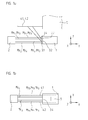
- the researcher In the measuring or machine position according to FIG. 2a is the object and thus the conferencever analysesungs reflector unit 30 'along the second main axis of movement x in a position in which the measuring beam My the first position measuring device on the area 3.4a' applies, ie on the trained example as a plane mirror measuring reflector. From there, the measuring beam My is reflected back in the direction of the optical unit - not shown.
- the first position measuring device operates in a known manner and is used inter alia for detecting the object position along the first main axis of movement y.
- measuring beam Mz of the second position-measuring device likewise shown acts in this position on the track 3.2 'with the measuring standard arranged there as well as the diffraction grating of the reflector 4.1'.
- the detection of the object position along the second measuring direction or the third axis z is possible.
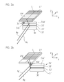
- the measuring beam My of the first position measuring device then hits the second area 3.4b 'in the corresponding track 3.4'.
- the measuring standard arranged there causes a deflection of the measuring beam My 'analogously to the deflection of the measuring beam Mz of the second position measuring device in the direction of the diffraction grating 4.1b' to be calibrated on the reflector 4.1 '.
- the diffraction grating 4.1b 'on the reflector 4.1' is now scanned twice along the scanning line L during a resulting object movement along the first main movement direction y, ie along the first main axis of movement y or along the first measuring direction. Self-calibration of the diffraction grating 4.1b ' on the reflector 4.1 'is thus possible without the need for an additional optical or scanning unit is required.
- the first position measuring device which actually serves primarily for the position detection along the first measuring direction or the first main axis of movement y, can be switched in this position such that a position detection along another measuring direction, namely along the third axis z, is also possible.
- the diffraction gratings 4.1a, 4.2a are provided in the third position measuring device of the present arrangement, via which a position detection of the object 1 takes place along the second main axis of movement x.
- this position measuring device is explicitly on the DE 10 2012 201 393.3 where this position measuring device is referred to as the second position measuring device.
- the measuring graduation reflector unit 3 comprises a further track 3.1 with differently designed regions 3.1a, 3.1b, as is apparent from FIG Figure 1d is apparent.
- the areas 3.1b are provided with a material measure in order to deflect or deflect the measuring beam incident thereon in the direction of the positions Diffraction gratings 4.1a, 4.2a on the reflectors 4.1, 4.2 to effect and about a second scan derselbigen to allow, if in this position, an object movement along the first main axis of motion y occurs.
- the position signals of the switched first position-measuring device and the third position-measuring device are fed to a calibration unit, not shown again.
- the first position measuring device in the illustrated arrangement is designed as a 4-axis interferometer. It is also ensured that, for example, during the self-calibration of the reflectors along the first main axis of motion y, eg by means of a correspondingly deflected measuring beam My 1 , a determination of the position and orientation of the object via the three other measuring beams My 2 , My 3 and My 4 is possible is.
- the desired measuring direction, along which a scan or position detection is to take place, is set according to the invention exclusively by suitable modifications on the part of the material measure reflector unit 3; a plan view of this is in Figure 1d shown.
- On the part of the optical unit 2 of the first position measuring device no changes are required.
- differently shaped areas 3.4a, 3.4b and 3.1a, 3.1b in the tracks 3.1, 3.4 the material measure reflector unit 3 learn the incident thereon beams of the respective measuring beams each have different deflection and / or deflection effects.
- a first region 3, 1a, 3.4a which serves to generate the primary position signals of the respective position-measuring device, extends over a large part of the track 3.1, 3.4 and the second, differently formed region 3.1b, 3.4b, which serves for position signal generation in the switched mode, extends only over a significantly smaller area of the track 3.1, 3.4.
- the first region 3, 1a, 3.4a are arranged centrally in the track 3.1, 3.4, and only at at least one end a differently configured second region 3, 1b, 3.4b are provided, as described in US Pat illustrated embodiment of the material measure reflector unit 3 in Figure 1d is realized.
- Such a measuring direction switching can also be used in other applications, regardless of the discussed self-calibration. For example, it may be advantageous to detect a single measuring direction particularly accurately or at a reduced Abbe distance at a specific position of a table in order, for example, to touch a reference mark. By switching a redundant measuring axis from another measuring direction used in the other operation to the measuring direction which is to be detected particularly accurately, positions along this measuring axis can be measured redundantly and thus more accurately.
Landscapes
- Physics & Mathematics (AREA)
- General Physics & Mathematics (AREA)
- Engineering & Computer Science (AREA)
- Electromagnetism (AREA)
- Remote Sensing (AREA)
- Radar, Positioning & Navigation (AREA)
- Computer Networks & Wireless Communication (AREA)
- Manufacturing & Machinery (AREA)
- Computer Hardware Design (AREA)
- Microelectronics & Electronic Packaging (AREA)
- Power Engineering (AREA)
- Length Measuring Devices By Optical Means (AREA)
- Optical Transform (AREA)
Claims (13)
- Agencement avec un premier et un deuxième dispositif de mesure de la position destinés à détecter la position d'un premier objet (1) par rapport à un deuxième objet (5), le premier et le deuxième objet étant disposés en étant mobiles l'un par rapport à l'autre le long d'au moins deux directions de mesure (x, y, z) et la position du premier objet le long de la première direction de mesure étant détectable avec le premier dispositif de mesure de la position, et la position du deuxième objet le long de la deuxième direction de mesure étant détectable avec le deuxième dispositif de mesure de la position, avec- un ensemble optique (2) qui est relié à l'un des deux objets (5) et qui comprend au moins une source lumineuse, un agencement de détecteurs, ainsi qu'un élément optique supplémentaire selon une disposition définie et- un ensemble de réflecteurs et mesures matérialisées (3, 30'), lequel est placé sur l'autre objet (1) et comporte au moins deux régions (3.1a, 3.1b, 3.4a, 3.4b, 3.4a', 3.4b') de conception différente dans une voie (3.1, 3.4, 3.4'), qui pour la détection de la position peuvent être balayées optiquement par l'ensemble optique (2), du fait de la conception différente des régions (3.1a, 3.1b, 3.4a, 3.4b, 3.4a', 3.4b'), lors de la détection de la position, une commutation entre les différentes directions de mesure (x, y, z) étant possible et pour chaque direction de mesure (x, y, z), avec l'ensemble optique (2), chaque fois des signaux de position concernant le déplacement relatif des deux objets (1, 5) pouvant être générés.
- Agencement selon la revendication 1, dans les différentes régions (3.1a, 3.1b, 3.4a, 3.4b, 3.4a', 3.4b') de la voie (3.1, 3.4, 3.4') de l'ensemble de réflecteurs et mesures matérialisées (3, 30') étant placés des réflecteurs de mesure et des mesures matérialisées.
- Agencement selon la revendication 2, les réflecteurs de mesure étant conçus en tant que miroirs plans et les mesures matérialisées étant conçues en tant que réseaux de diffraction à lumière incidente.
- Agencement selon la revendication 2, des faisceaux lumineux qui sont incidents sur les régions (3.1a, 3.1b, 3.4a, 3.4b, 3.4a', 3.4b') de conception différente étant soumis à différents effets de déflexion ou de diffraction.
- Agencement selon la revendication 1, l'ensemble de réflecteurs et mesures matérialisées (3, 30') comportant plusieurs voies (3.1 à 3.4, 3.1' à 3.4') placées de manière parallèle dans lesquelles sont placé(e)s des mesures matérialisées et/ou des réflecteurs de mesure.
- Agencement selon la revendication 5,- dans une voie (3.2, 3.3, 3.2') étant placée une mesure matérialisée et- dans une autre voie (3.1, 3.4, 3.4') dans une première région (3.1a, 3.4a, 3.4a') étant placé un réflecteur de mesure et dans une deuxième région (3.1b, 3.4b, 3.4b') étant placée une mesure matérialisée qui est conçue à l'identique de la mesure matérialisée dans l'autre voie (3.2, 3.3, 3.2').
- Agencement selon au moins l'une quelconque des revendications précédentes, le long de la direction d'extension de la voie (3.1, 3.4, 3.4'), une première région centrale (3.1a, 3.4a, 3.4a') étant placée dans la voie (3.1, 3.4, 3.4') et au moins sur une extrémité de la première région, une deuxième région (3.1b, 3.4b, 3.4b') de conception différente étant placée dans la voie (3.1, 3.4, 3.4').
- Agencement selon au moins l'une quelconque des revendications précédentes, dans la voie (3.1, 3.4, 3.4') étant placée une première région (3.1a, 3.4a, 3.4a') qui s'étend sur la majeure partie de la voie (3.1, 3.4, 3.4'), et une deuxième région (3.1b, 3.4b, 3.4b') de conception différente qui s'étend seulement sur une région nettement plus petite de la voie (3.1, 3.4, 3.4') étant placée dans la voie (3.1, 3.4, 3.4').
- Agencement selon l'une quelconque des revendications précédentes et avec- un premier objet (1) qui est placé en étant mobile le long de deux axes orthogonaux et d'un premier et un deuxième axe de déplacement principal (y, x), ainsi que le long d'un troisième axe (z), par rapport à ces derniers,- le premier axe de déplacement principal (y) faisant office de première direction de mesure,- le troisième axe (z) faisant office de deuxième direction de mesure et- le deuxième axe de déplacement principal (x) faisant office de troisième direction de mesure
et- un deuxième objet (5) qui est placé de manière stationnaire par rapport au premier objet, l'ensemble optique (2) étant placé sur le deuxième objet (5) et- sur le premier objet (1) étant placé l'ensemble de réflecteurs et mesures matérialisées (3) qui s'étend le long du deuxième axe de déplacement principal (x) qui comprend une voie (3.1, 3.4) avec une première région (3.1a, 3.4a) avec un premier réflecteur de mesure et une deuxième région (3.1b, 3.4b) avec une mesure matérialisée, de sorte que lors du balayage optique de la première région (3.1a, 3.4a), des signaux de position concernant un déplacement du premier objet (1) le long de la première direction de mesure (y) peuvent être générés et lors du balayage optique de la deuxième région (3.1b, 3.4b), des signaux de position supplémentaires concernant un déplacement du premier objet (1) le long de la deuxième direction de mesure (x) ou le long de la troisième direction de mesure (z) peuvent être générés. - Agencement selon la revendication 9 qui comprend un troisième dispositif de mesure de la position, par l'intermédiaire duquel des signaux de position concernant un déplacement du premier objet (1) le long de la troisième direction de mesure (x) peuvent être générés.
- Agencement selon la revendication 10, sur lequel, dans le cas du balayage optique de la mesure matérialisée dans la deuxième région et de la génération simultanée de signaux de position au moyen du deuxième ou du troisième dispositif de mesure de la position, pendant un mouvement de déplacement le long de la première direction de mesure (y), il s'effectue chaque fois un double balayage d'un réflecteur (4.1, 4.2) du deuxième ou du troisième dispositif de mesure de la position le long de la première direction de mesure (y).
- Agencement selon la revendication 11,- les signaux de position du premier et du deuxième dispositif de mesure de la position pouvant être amenés vers un ensemble de calibrage et/ou- les signaux de position du premier et du troisième dispositif de mesure de la position pouvant être amenés vers un ensemble de calibrage.
- Agencement selon la revendication 9, le premier dispositif de mesure de la position étant conçu en tant qu'interféromètre multiaxes avec quatre rayons de mesure (My1, My2, My3, My4).
Applications Claiming Priority (1)
| Application Number | Priority Date | Filing Date | Title |
|---|---|---|---|
| DE102012204572A DE102012204572A1 (de) | 2012-03-22 | 2012-03-22 | Positionsmesseinrichtung und Anordnung mit einer derartigen Positionsmesseinrichtung |
Publications (3)
| Publication Number | Publication Date |
|---|---|
| EP2642254A2 EP2642254A2 (fr) | 2013-09-25 |
| EP2642254A3 EP2642254A3 (fr) | 2015-04-15 |
| EP2642254B1 true EP2642254B1 (fr) | 2015-11-25 |
Family
ID=47827024
Family Applications (1)
| Application Number | Title | Priority Date | Filing Date |
|---|---|---|---|
| EP13157956.7A Active EP2642254B1 (fr) | 2012-03-22 | 2013-03-06 | Arrangement comportant un premier et un second dispositif de mesure de position |
Country Status (6)
| Country | Link |
|---|---|
| US (1) | US9389065B2 (fr) |
| EP (1) | EP2642254B1 (fr) |
| JP (1) | JP6278605B2 (fr) |
| KR (1) | KR101864770B1 (fr) |
| CN (1) | CN103322910B (fr) |
| DE (1) | DE102012204572A1 (fr) |
Families Citing this family (20)
| Publication number | Priority date | Publication date | Assignee | Title |
|---|---|---|---|---|
| EP2936052B1 (fr) | 2012-12-19 | 2021-04-28 | Basf Se | Détecteur pour détecter de manière optique au moins un objet |
| JP2016529473A (ja) | 2013-06-13 | 2016-09-23 | ビーエーエスエフ ソシエタス・ヨーロピアBasf Se | 少なくとも1つの物体を光学的に検出する検出器 |
| EP3008421A1 (fr) | 2013-06-13 | 2016-04-20 | Basf Se | Détecteur permettant de détecter optiquement l'orientation d'au moins un objet |
| CN105637382B (zh) | 2013-08-19 | 2017-08-25 | 巴斯夫欧洲公司 | 用于确定至少一种物体的位置的检测器 |
| EP3036503B1 (fr) | 2013-08-19 | 2019-08-07 | Basf Se | Détecteur optique |
| CN106662636B (zh) | 2014-07-08 | 2020-12-25 | 巴斯夫欧洲公司 | 用于确定至少一个对象的位置的检测器 |
| US10094927B2 (en) | 2014-09-29 | 2018-10-09 | Basf Se | Detector for optically determining a position of at least one object |
| US11125880B2 (en) | 2014-12-09 | 2021-09-21 | Basf Se | Optical detector |
| JP6841769B2 (ja) | 2015-01-30 | 2021-03-10 | トリナミクス ゲゼルシャフト ミット ベシュレンクテル ハフツング | 少なくとも1個の物体を光学的に検出する検出器 |
| KR102644439B1 (ko) | 2015-07-17 | 2024-03-07 | 트리나미엑스 게엠베하 | 하나 이상의 물체를 광학적으로 검출하기 위한 검출기 |
| WO2017046121A1 (fr) | 2015-09-14 | 2017-03-23 | Trinamix Gmbh | Appareil photo 3d |
| JP2019523562A (ja) | 2016-07-29 | 2019-08-22 | トリナミクス ゲゼルシャフト ミット ベシュレンクテル ハフツング | 光学的検出のための光センサおよび検出器 |
| WO2018077868A1 (fr) | 2016-10-25 | 2018-05-03 | Trinamix Gmbh | Détecteur pour détection optique d'au moins un objet |
| US10890491B2 (en) | 2016-10-25 | 2021-01-12 | Trinamix Gmbh | Optical detector for an optical detection |
| US11860292B2 (en) | 2016-11-17 | 2024-01-02 | Trinamix Gmbh | Detector and methods for authenticating at least one object |
| WO2018091640A2 (fr) | 2016-11-17 | 2018-05-24 | Trinamix Gmbh | Détecteur pouvant détecter optiquement au moins un objet |
| WO2018193045A1 (fr) | 2017-04-20 | 2018-10-25 | Trinamix Gmbh | Détecteur optique |
| US11067692B2 (en) | 2017-06-26 | 2021-07-20 | Trinamix Gmbh | Detector for determining a position of at least one object |
| JP7141313B2 (ja) * | 2018-11-06 | 2022-09-22 | Dmg森精機株式会社 | 変位検出装置 |
| CN111721210B (zh) * | 2020-06-19 | 2021-11-12 | 深圳市汉森软件有限公司 | 变换逻辑光栅分辨率后的初始化方法、装置、设备及介质 |
Family Cites Families (24)
| Publication number | Priority date | Publication date | Assignee | Title |
|---|---|---|---|---|
| JPH08247790A (ja) * | 1995-03-10 | 1996-09-27 | Sefuto Kenkyusho:Kk | 位置検出装置 |
| DE19633337A1 (de) * | 1996-08-07 | 1998-02-12 | Harry Prof Dr Ing Trumpold | Positionsmeßsystem |
| JP4576014B2 (ja) * | 1999-12-21 | 2010-11-04 | オリンパス株式会社 | 光学式エンコーダー |
| CN1248058C (zh) * | 2000-09-14 | 2006-03-29 | 约翰尼斯海登海恩博士股份有限公司 | 位置测量装置 |
| US7102729B2 (en) * | 2004-02-03 | 2006-09-05 | Asml Netherlands B.V. | Lithographic apparatus, measurement system, and device manufacturing method |
| DE102005029917A1 (de) * | 2005-06-28 | 2007-01-04 | Dr. Johannes Heidenhain Gmbh | Positionsmesseinrichtung |
| JP4593625B2 (ja) * | 2005-09-21 | 2010-12-08 | パナソニック株式会社 | 角度測定装置及び方法 |
| JP4932284B2 (ja) * | 2006-03-03 | 2012-05-16 | 株式会社ミツトヨ | 光電式エンコーダ |
| JP4601006B2 (ja) | 2006-09-29 | 2010-12-22 | 本田技研工業株式会社 | エアクリーナ装置 |
| JP2008108906A (ja) * | 2006-10-25 | 2008-05-08 | Canon Inc | 位置決め装置 |
| JP5147368B2 (ja) * | 2006-11-20 | 2013-02-20 | ドクトル・ヨハネス・ハイデンハイン・ゲゼルシヤフト・ミツト・ベシユレンクテル・ハフツング | エンコーダ |
| DE102007035345A1 (de) * | 2006-11-20 | 2008-05-21 | Dr. Johannes Heidenhain Gmbh | Positionsmesseinrichtung |
| DE102008008873A1 (de) * | 2007-05-16 | 2008-11-20 | Dr. Johannes Heidenhain Gmbh | Positionsmesseinrichtung |
| US7804579B2 (en) | 2007-06-21 | 2010-09-28 | Asml Netherlands B.V. | Control system, lithographic projection apparatus, method of controlling a support structure, and a computer program product |
| US8174671B2 (en) * | 2007-06-21 | 2012-05-08 | Asml Netherlands B.V. | Lithographic projection apparatus and method for controlling a support structure |
| US8208128B2 (en) * | 2008-02-08 | 2012-06-26 | Nikon Corporation | Position measuring system and position measuring method, Movable body apparatus, movable body drive method, exposure apparatus and exposure method, pattern forming apparatus, and device manufacturing method |
| KR20100041024A (ko) * | 2008-10-13 | 2010-04-22 | 한국표준과학연구원 | 2차원 회절 격자를 이용한 6 자유도 측정 장치 |
| JP4283878B2 (ja) | 2008-10-24 | 2009-06-24 | キヤノンアネルバ株式会社 | マグネトロンスパッタリング装置 |
| JP2010205867A (ja) * | 2009-03-03 | 2010-09-16 | Canon Inc | 位置検出装置及び露光装置 |
| KR101078781B1 (ko) * | 2010-02-01 | 2011-11-01 | 주식회사 고영테크놀러지 | 3차원 형상 검사방법 |
| KR101725529B1 (ko) * | 2010-03-30 | 2017-04-10 | 지고 코포레이션 | 간섭계 인코더 시스템 |
| JP5656467B2 (ja) * | 2010-06-17 | 2015-01-21 | Dmg森精機株式会社 | 位置検出装置 |
| JP5754971B2 (ja) * | 2011-02-14 | 2015-07-29 | キヤノン株式会社 | 形状測定装置及び形状測定方法 |
| DE102012201393A1 (de) | 2012-02-01 | 2013-08-01 | Dr. Johannes Heidenhain Gmbh | Positionsmesseinrichtung und Anordnung mit mehreren Positionsmesseinrichtungen |
-
2012
- 2012-03-22 DE DE102012204572A patent/DE102012204572A1/de not_active Withdrawn
-
2013
- 2013-03-06 EP EP13157956.7A patent/EP2642254B1/fr active Active
- 2013-03-08 KR KR1020130025270A patent/KR101864770B1/ko active IP Right Grant
- 2013-03-18 US US13/845,988 patent/US9389065B2/en active Active
- 2013-03-19 JP JP2013056864A patent/JP6278605B2/ja active Active
- 2013-03-22 CN CN201310093649.8A patent/CN103322910B/zh active Active
Also Published As
| Publication number | Publication date |
|---|---|
| JP2013195432A (ja) | 2013-09-30 |
| DE102012204572A1 (de) | 2013-09-26 |
| US20130235390A1 (en) | 2013-09-12 |
| KR20130108121A (ko) | 2013-10-02 |
| KR101864770B1 (ko) | 2018-06-05 |
| JP6278605B2 (ja) | 2018-02-14 |
| US9389065B2 (en) | 2016-07-12 |
| EP2642254A2 (fr) | 2013-09-25 |
| CN103322910A (zh) | 2013-09-25 |
| EP2642254A3 (fr) | 2015-04-15 |
| CN103322910B (zh) | 2017-10-27 |
Similar Documents
| Publication | Publication Date | Title |
|---|---|---|
| EP2642254B1 (fr) | Arrangement comportant un premier et un second dispositif de mesure de position | |
| EP2623937B1 (fr) | Dispositif de mesure de position et agencement à plusieurs dispositifs de mesure de position | |
| EP2149029B1 (fr) | Dispositif de mesure de position | |
| EP2660566B1 (fr) | Codeur optique pour déterminer la position de deux parties deplaçable l'une par rapport à l'autre dans deux directions de déplacement | |
| EP2450672B1 (fr) | Dispositif de mesure d'angle optique | |
| EP2247915B1 (fr) | Table xy comprenant un système de mesure pour la détermination de position | |
| DE102017100991B3 (de) | Messvorrichtung und Verfahren zur Erfassung wenigstens einer Längenmessgröße | |
| EP3175949B1 (fr) | Machine-outil | |
| EP2450673B1 (fr) | Dispositif optique de mesure de la position | |
| DE102011011065B4 (de) | Verfahren und Vorrichtung zur hochpräzisen Vermessung von Oberflächen | |
| EP2857802A2 (fr) | Dispositif optique de mesure de position | |
| EP2857901B1 (fr) | Système de positionnement d'un outil par rapport à une pièce à usiner | |
| EP2746731B1 (fr) | Dispositif optique de mesure de la position | |
| DE102013201484A1 (de) | Anordnung mit mehreren Abtasteinheiten einer Positionsmesseinrichtung | |
| DE112018004038T5 (de) | Messung der Position von Objekten im Raum | |
| EP2878930B1 (fr) | Dispositif de mesure de position | |
| EP3351895B1 (fr) | Appareil de mesure et procédé pour opérer un appareil de mesure | |
| EP3869161B1 (fr) | Dispositif optique de mesure de position | |
| DE102013201513A1 (de) | Anordnung und Verfahren zur Positionierung eines Bearbeitungswerkzeuges gegenüber einem Werkstück | |
| EP2032948A1 (fr) | Dispositif de détermination de la position d'un objet déplaçable le long d'au moins une direction de déplacement | |
| EP3443303A1 (fr) | Ensemble de mesure de position et procédé pour faire fonctionner un ensemble de mesure de position | |
| EP3833930B1 (fr) | Dispositif et procédé destinés à la mesure géométrique d'un objet | |
| DE10043828B4 (de) | Abtasteinheit für eine optische Positionsmesseinrichtung | |
| DE19822129A1 (de) | Anordnung und Meßverfahren zur Fluchtung höchster Präzision mit zweidimensionalen optischen Symmetrierelementen | |
| DE19828815A1 (de) | Laserinterferometer zur zweiachsigen Positionsmessung von bewegten Maschinenkomponenten |
Legal Events
| Date | Code | Title | Description |
|---|---|---|---|
| PUAI | Public reference made under article 153(3) epc to a published international application that has entered the european phase |
Free format text: ORIGINAL CODE: 0009012 |
|
| AK | Designated contracting states |
Kind code of ref document: A2 Designated state(s): AL AT BE BG CH CY CZ DE DK EE ES FI FR GB GR HR HU IE IS IT LI LT LU LV MC MK MT NL NO PL PT RO RS SE SI SK SM TR |
|
| AX | Request for extension of the european patent |
Extension state: BA ME |
|
| PUAL | Search report despatched |
Free format text: ORIGINAL CODE: 0009013 |
|
| AK | Designated contracting states |
Kind code of ref document: A3 Designated state(s): AL AT BE BG CH CY CZ DE DK EE ES FI FR GB GR HR HU IE IS IT LI LT LU LV MC MK MT NL NO PL PT RO RS SE SI SK SM TR |
|
| AX | Request for extension of the european patent |
Extension state: BA ME |
|
| RIC1 | Information provided on ipc code assigned before grant |
Ipc: G01D 5/347 20060101AFI20150312BHEP |
|
| 17P | Request for examination filed |
Effective date: 20150429 |
|
| RBV | Designated contracting states (corrected) |
Designated state(s): AL AT BE BG CH CY CZ DE DK EE ES FI FR GB GR HR HU IE IS IT LI LT LU LV MC MK MT NL NO PL PT RO RS SE SI SK SM TR |
|
| GRAP | Despatch of communication of intention to grant a patent |
Free format text: ORIGINAL CODE: EPIDOSNIGR1 |
|
| INTG | Intention to grant announced |
Effective date: 20150825 |
|
| GRAS | Grant fee paid |
Free format text: ORIGINAL CODE: EPIDOSNIGR3 |
|
| GRAA | (expected) grant |
Free format text: ORIGINAL CODE: 0009210 |
|
| AK | Designated contracting states |
Kind code of ref document: B1 Designated state(s): AL AT BE BG CH CY CZ DE DK EE ES FI FR GB GR HR HU IE IS IT LI LT LU LV MC MK MT NL NO PL PT RO RS SE SI SK SM TR |
|
| REG | Reference to a national code |
Ref country code: GB Ref legal event code: FG4D Free format text: NOT ENGLISH |
|
| REG | Reference to a national code |
Ref country code: CH Ref legal event code: EP |
|
| REG | Reference to a national code |
Ref country code: AT Ref legal event code: REF Ref document number: 762843 Country of ref document: AT Kind code of ref document: T Effective date: 20151215 |
|
| REG | Reference to a national code |
Ref country code: IE Ref legal event code: FG4D Free format text: LANGUAGE OF EP DOCUMENT: GERMAN |
|
| REG | Reference to a national code |
Ref country code: DE Ref legal event code: R096 Ref document number: 502013001532 Country of ref document: DE |
|
| REG | Reference to a national code |
Ref country code: LT Ref legal event code: MG4D |
|
| REG | Reference to a national code |
Ref country code: NL Ref legal event code: MP Effective date: 20160225 |
|
| PG25 | Lapsed in a contracting state [announced via postgrant information from national office to epo] |
Ref country code: NL Free format text: LAPSE BECAUSE OF FAILURE TO SUBMIT A TRANSLATION OF THE DESCRIPTION OR TO PAY THE FEE WITHIN THE PRESCRIBED TIME-LIMIT Effective date: 20151125 Ref country code: LT Free format text: LAPSE BECAUSE OF FAILURE TO SUBMIT A TRANSLATION OF THE DESCRIPTION OR TO PAY THE FEE WITHIN THE PRESCRIBED TIME-LIMIT Effective date: 20151125 Ref country code: NO Free format text: LAPSE BECAUSE OF FAILURE TO SUBMIT A TRANSLATION OF THE DESCRIPTION OR TO PAY THE FEE WITHIN THE PRESCRIBED TIME-LIMIT Effective date: 20160225 Ref country code: HR Free format text: LAPSE BECAUSE OF FAILURE TO SUBMIT A TRANSLATION OF THE DESCRIPTION OR TO PAY THE FEE WITHIN THE PRESCRIBED TIME-LIMIT Effective date: 20151125 Ref country code: ES Free format text: LAPSE BECAUSE OF FAILURE TO SUBMIT A TRANSLATION OF THE DESCRIPTION OR TO PAY THE FEE WITHIN THE PRESCRIBED TIME-LIMIT Effective date: 20151125 Ref country code: IS Free format text: LAPSE BECAUSE OF FAILURE TO SUBMIT A TRANSLATION OF THE DESCRIPTION OR TO PAY THE FEE WITHIN THE PRESCRIBED TIME-LIMIT Effective date: 20160325 |
|
| PG25 | Lapsed in a contracting state [announced via postgrant information from national office to epo] |
Ref country code: GR Free format text: LAPSE BECAUSE OF FAILURE TO SUBMIT A TRANSLATION OF THE DESCRIPTION OR TO PAY THE FEE WITHIN THE PRESCRIBED TIME-LIMIT Effective date: 20160226 Ref country code: PT Free format text: LAPSE BECAUSE OF FAILURE TO SUBMIT A TRANSLATION OF THE DESCRIPTION OR TO PAY THE FEE WITHIN THE PRESCRIBED TIME-LIMIT Effective date: 20160325 Ref country code: LV Free format text: LAPSE BECAUSE OF FAILURE TO SUBMIT A TRANSLATION OF THE DESCRIPTION OR TO PAY THE FEE WITHIN THE PRESCRIBED TIME-LIMIT Effective date: 20151125 Ref country code: SE Free format text: LAPSE BECAUSE OF FAILURE TO SUBMIT A TRANSLATION OF THE DESCRIPTION OR TO PAY THE FEE WITHIN THE PRESCRIBED TIME-LIMIT Effective date: 20151125 Ref country code: RS Free format text: LAPSE BECAUSE OF FAILURE TO SUBMIT A TRANSLATION OF THE DESCRIPTION OR TO PAY THE FEE WITHIN THE PRESCRIBED TIME-LIMIT Effective date: 20151125 Ref country code: FI Free format text: LAPSE BECAUSE OF FAILURE TO SUBMIT A TRANSLATION OF THE DESCRIPTION OR TO PAY THE FEE WITHIN THE PRESCRIBED TIME-LIMIT Effective date: 20151125 Ref country code: PL Free format text: LAPSE BECAUSE OF FAILURE TO SUBMIT A TRANSLATION OF THE DESCRIPTION OR TO PAY THE FEE WITHIN THE PRESCRIBED TIME-LIMIT Effective date: 20151125 |
|
| PG25 | Lapsed in a contracting state [announced via postgrant information from national office to epo] |
Ref country code: CZ Free format text: LAPSE BECAUSE OF FAILURE TO SUBMIT A TRANSLATION OF THE DESCRIPTION OR TO PAY THE FEE WITHIN THE PRESCRIBED TIME-LIMIT Effective date: 20151125 Ref country code: IT Free format text: LAPSE BECAUSE OF FAILURE TO SUBMIT A TRANSLATION OF THE DESCRIPTION OR TO PAY THE FEE WITHIN THE PRESCRIBED TIME-LIMIT Effective date: 20151125 |
|
| REG | Reference to a national code |
Ref country code: DE Ref legal event code: R097 Ref document number: 502013001532 Country of ref document: DE |
|
| PG25 | Lapsed in a contracting state [announced via postgrant information from national office to epo] |
Ref country code: RO Free format text: LAPSE BECAUSE OF FAILURE TO SUBMIT A TRANSLATION OF THE DESCRIPTION OR TO PAY THE FEE WITHIN THE PRESCRIBED TIME-LIMIT Effective date: 20151125 Ref country code: EE Free format text: LAPSE BECAUSE OF FAILURE TO SUBMIT A TRANSLATION OF THE DESCRIPTION OR TO PAY THE FEE WITHIN THE PRESCRIBED TIME-LIMIT Effective date: 20151125 Ref country code: DK Free format text: LAPSE BECAUSE OF FAILURE TO SUBMIT A TRANSLATION OF THE DESCRIPTION OR TO PAY THE FEE WITHIN THE PRESCRIBED TIME-LIMIT Effective date: 20151125 Ref country code: BE Free format text: LAPSE BECAUSE OF NON-PAYMENT OF DUE FEES Effective date: 20160331 Ref country code: SM Free format text: LAPSE BECAUSE OF FAILURE TO SUBMIT A TRANSLATION OF THE DESCRIPTION OR TO PAY THE FEE WITHIN THE PRESCRIBED TIME-LIMIT Effective date: 20151125 Ref country code: SK Free format text: LAPSE BECAUSE OF FAILURE TO SUBMIT A TRANSLATION OF THE DESCRIPTION OR TO PAY THE FEE WITHIN THE PRESCRIBED TIME-LIMIT Effective date: 20151125 |
|
| PLBE | No opposition filed within time limit |
Free format text: ORIGINAL CODE: 0009261 |
|
| STAA | Information on the status of an ep patent application or granted ep patent |
Free format text: STATUS: NO OPPOSITION FILED WITHIN TIME LIMIT |
|
| PG25 | Lapsed in a contracting state [announced via postgrant information from national office to epo] |
Ref country code: LU Free format text: LAPSE BECAUSE OF FAILURE TO SUBMIT A TRANSLATION OF THE DESCRIPTION OR TO PAY THE FEE WITHIN THE PRESCRIBED TIME-LIMIT Effective date: 20160306 Ref country code: MC Free format text: LAPSE BECAUSE OF FAILURE TO SUBMIT A TRANSLATION OF THE DESCRIPTION OR TO PAY THE FEE WITHIN THE PRESCRIBED TIME-LIMIT Effective date: 20151125 |
|
| REG | Reference to a national code |
Ref country code: CH Ref legal event code: PL |
|
| 26N | No opposition filed |
Effective date: 20160826 |
|
| PG25 | Lapsed in a contracting state [announced via postgrant information from national office to epo] |
Ref country code: SI Free format text: LAPSE BECAUSE OF FAILURE TO SUBMIT A TRANSLATION OF THE DESCRIPTION OR TO PAY THE FEE WITHIN THE PRESCRIBED TIME-LIMIT Effective date: 20151125 |
|
| REG | Reference to a national code |
Ref country code: IE Ref legal event code: MM4A |
|
| REG | Reference to a national code |
Ref country code: FR Ref legal event code: ST Effective date: 20161130 |
|
| PG25 | Lapsed in a contracting state [announced via postgrant information from national office to epo] |
Ref country code: FR Free format text: LAPSE BECAUSE OF NON-PAYMENT OF DUE FEES Effective date: 20160331 Ref country code: LI Free format text: LAPSE BECAUSE OF NON-PAYMENT OF DUE FEES Effective date: 20160331 Ref country code: IE Free format text: LAPSE BECAUSE OF NON-PAYMENT OF DUE FEES Effective date: 20160306 Ref country code: CH Free format text: LAPSE BECAUSE OF NON-PAYMENT OF DUE FEES Effective date: 20160331 |
|
| PG25 | Lapsed in a contracting state [announced via postgrant information from national office to epo] |
Ref country code: MT Free format text: LAPSE BECAUSE OF FAILURE TO SUBMIT A TRANSLATION OF THE DESCRIPTION OR TO PAY THE FEE WITHIN THE PRESCRIBED TIME-LIMIT Effective date: 20151125 |
|
| PG25 | Lapsed in a contracting state [announced via postgrant information from national office to epo] |
Ref country code: CY Free format text: LAPSE BECAUSE OF FAILURE TO SUBMIT A TRANSLATION OF THE DESCRIPTION OR TO PAY THE FEE WITHIN THE PRESCRIBED TIME-LIMIT Effective date: 20151125 Ref country code: HU Free format text: LAPSE BECAUSE OF FAILURE TO SUBMIT A TRANSLATION OF THE DESCRIPTION OR TO PAY THE FEE WITHIN THE PRESCRIBED TIME-LIMIT; INVALID AB INITIO Effective date: 20130306 |
|
| PG25 | Lapsed in a contracting state [announced via postgrant information from national office to epo] |
Ref country code: TR Free format text: LAPSE BECAUSE OF FAILURE TO SUBMIT A TRANSLATION OF THE DESCRIPTION OR TO PAY THE FEE WITHIN THE PRESCRIBED TIME-LIMIT Effective date: 20151125 Ref country code: MK Free format text: LAPSE BECAUSE OF FAILURE TO SUBMIT A TRANSLATION OF THE DESCRIPTION OR TO PAY THE FEE WITHIN THE PRESCRIBED TIME-LIMIT Effective date: 20151125 |
|
| PG25 | Lapsed in a contracting state [announced via postgrant information from national office to epo] |
Ref country code: BG Free format text: LAPSE BECAUSE OF FAILURE TO SUBMIT A TRANSLATION OF THE DESCRIPTION OR TO PAY THE FEE WITHIN THE PRESCRIBED TIME-LIMIT Effective date: 20151125 |
|
| PG25 | Lapsed in a contracting state [announced via postgrant information from national office to epo] |
Ref country code: AL Free format text: LAPSE BECAUSE OF FAILURE TO SUBMIT A TRANSLATION OF THE DESCRIPTION OR TO PAY THE FEE WITHIN THE PRESCRIBED TIME-LIMIT Effective date: 20151125 |
|
| REG | Reference to a national code |
Ref country code: AT Ref legal event code: MM01 Ref document number: 762843 Country of ref document: AT Kind code of ref document: T Effective date: 20180306 |
|
| PG25 | Lapsed in a contracting state [announced via postgrant information from national office to epo] |
Ref country code: AT Free format text: LAPSE BECAUSE OF NON-PAYMENT OF DUE FEES Effective date: 20180306 |
|
| PGFP | Annual fee paid to national office [announced via postgrant information from national office to epo] |
Ref country code: DE Payment date: 20240320 Year of fee payment: 12 Ref country code: GB Payment date: 20240320 Year of fee payment: 12 |