EP2640600B1 - Verstellvorrichtung eines fahrzeugsitzes mit einer selbstverstellbremse - Google Patents
Verstellvorrichtung eines fahrzeugsitzes mit einer selbstverstellbremse Download PDFInfo
- Publication number
- EP2640600B1 EP2640600B1 EP11790869.9A EP11790869A EP2640600B1 EP 2640600 B1 EP2640600 B1 EP 2640600B1 EP 11790869 A EP11790869 A EP 11790869A EP 2640600 B1 EP2640600 B1 EP 2640600B1
- Authority
- EP
- European Patent Office
- Prior art keywords
- adjusting device
- gearwheel
- locking contour
- gear
- fitting part
- Prior art date
- Legal status (The legal status is an assumption and is not a legal conclusion. Google has not performed a legal analysis and makes no representation as to the accuracy of the status listed.)
- Not-in-force
Links
- 230000000903 blocking effect Effects 0.000 claims description 15
- 238000007789 sealing Methods 0.000 claims description 7
- 230000033001 locomotion Effects 0.000 description 2
- 230000005540 biological transmission Effects 0.000 description 1
- 238000004146 energy storage Methods 0.000 description 1
- 239000012530 fluid Substances 0.000 description 1
- 238000007373 indentation Methods 0.000 description 1
- 239000007788 liquid Substances 0.000 description 1
- 239000003973 paint Substances 0.000 description 1
Images


Classifications
-
- A—HUMAN NECESSITIES
- A47—FURNITURE; DOMESTIC ARTICLES OR APPLIANCES; COFFEE MILLS; SPICE MILLS; SUCTION CLEANERS IN GENERAL
- A47C—CHAIRS; SOFAS; BEDS
- A47C7/00—Parts, details, or accessories of chairs or stools
- A47C7/36—Supports for the head or the back
- A47C7/40—Supports for the head or the back for the back
- A47C7/46—Supports for the head or the back for the back with special, e.g. adjustable, lumbar region support profile; "Ackerblom" profile chairs
- A47C7/462—Supports for the head or the back for the back with special, e.g. adjustable, lumbar region support profile; "Ackerblom" profile chairs adjustable by mechanical means
-
- B—PERFORMING OPERATIONS; TRANSPORTING
- B60—VEHICLES IN GENERAL
- B60N—SEATS SPECIALLY ADAPTED FOR VEHICLES; VEHICLE PASSENGER ACCOMMODATION NOT OTHERWISE PROVIDED FOR
- B60N2/00—Seats specially adapted for vehicles; Arrangement or mounting of seats in vehicles
- B60N2/02—Seats specially adapted for vehicles; Arrangement or mounting of seats in vehicles the seat or part thereof being movable, e.g. adjustable
- B60N2/22—Seats specially adapted for vehicles; Arrangement or mounting of seats in vehicles the seat or part thereof being movable, e.g. adjustable the back-rest being adjustable
- B60N2/225—Seats specially adapted for vehicles; Arrangement or mounting of seats in vehicles the seat or part thereof being movable, e.g. adjustable the back-rest being adjustable by cycloidal or planetary mechanisms
- B60N2/2252—Seats specially adapted for vehicles; Arrangement or mounting of seats in vehicles the seat or part thereof being movable, e.g. adjustable the back-rest being adjustable by cycloidal or planetary mechanisms in which the central axis of the gearing lies inside the periphery of an orbital gear, e.g. one gear without sun gear
-
- B—PERFORMING OPERATIONS; TRANSPORTING
- B60—VEHICLES IN GENERAL
- B60N—SEATS SPECIALLY ADAPTED FOR VEHICLES; VEHICLE PASSENGER ACCOMMODATION NOT OTHERWISE PROVIDED FOR
- B60N2/00—Seats specially adapted for vehicles; Arrangement or mounting of seats in vehicles
- B60N2/02—Seats specially adapted for vehicles; Arrangement or mounting of seats in vehicles the seat or part thereof being movable, e.g. adjustable
- B60N2/22—Seats specially adapted for vehicles; Arrangement or mounting of seats in vehicles the seat or part thereof being movable, e.g. adjustable the back-rest being adjustable
- B60N2/225—Seats specially adapted for vehicles; Arrangement or mounting of seats in vehicles the seat or part thereof being movable, e.g. adjustable the back-rest being adjustable by cycloidal or planetary mechanisms
-
- B—PERFORMING OPERATIONS; TRANSPORTING
- B60—VEHICLES IN GENERAL
- B60N—SEATS SPECIALLY ADAPTED FOR VEHICLES; VEHICLE PASSENGER ACCOMMODATION NOT OTHERWISE PROVIDED FOR
- B60N2/00—Seats specially adapted for vehicles; Arrangement or mounting of seats in vehicles
- B60N2/02—Seats specially adapted for vehicles; Arrangement or mounting of seats in vehicles the seat or part thereof being movable, e.g. adjustable
- B60N2/22—Seats specially adapted for vehicles; Arrangement or mounting of seats in vehicles the seat or part thereof being movable, e.g. adjustable the back-rest being adjustable
-
- B—PERFORMING OPERATIONS; TRANSPORTING
- B60—VEHICLES IN GENERAL
- B60N—SEATS SPECIALLY ADAPTED FOR VEHICLES; VEHICLE PASSENGER ACCOMMODATION NOT OTHERWISE PROVIDED FOR
- B60N2/00—Seats specially adapted for vehicles; Arrangement or mounting of seats in vehicles
- B60N2/02—Seats specially adapted for vehicles; Arrangement or mounting of seats in vehicles the seat or part thereof being movable, e.g. adjustable
- B60N2/22—Seats specially adapted for vehicles; Arrangement or mounting of seats in vehicles the seat or part thereof being movable, e.g. adjustable the back-rest being adjustable
- B60N2/225—Seats specially adapted for vehicles; Arrangement or mounting of seats in vehicles the seat or part thereof being movable, e.g. adjustable the back-rest being adjustable by cycloidal or planetary mechanisms
- B60N2/2254—Seats specially adapted for vehicles; Arrangement or mounting of seats in vehicles the seat or part thereof being movable, e.g. adjustable the back-rest being adjustable by cycloidal or planetary mechanisms provided with braking systems
-
- Y—GENERAL TAGGING OF NEW TECHNOLOGICAL DEVELOPMENTS; GENERAL TAGGING OF CROSS-SECTIONAL TECHNOLOGIES SPANNING OVER SEVERAL SECTIONS OF THE IPC; TECHNICAL SUBJECTS COVERED BY FORMER USPC CROSS-REFERENCE ART COLLECTIONS [XRACs] AND DIGESTS
- Y10—TECHNICAL SUBJECTS COVERED BY FORMER USPC
- Y10T—TECHNICAL SUBJECTS COVERED BY FORMER US CLASSIFICATION
- Y10T74/00—Machine element or mechanism
- Y10T74/18—Mechanical movements
- Y10T74/18568—Reciprocating or oscillating to or from alternating rotary
- Y10T74/18576—Reciprocating or oscillating to or from alternating rotary including screw and nut
- Y10T74/18752—Manually driven
-
- Y—GENERAL TAGGING OF NEW TECHNOLOGICAL DEVELOPMENTS; GENERAL TAGGING OF CROSS-SECTIONAL TECHNOLOGIES SPANNING OVER SEVERAL SECTIONS OF THE IPC; TECHNICAL SUBJECTS COVERED BY FORMER USPC CROSS-REFERENCE ART COLLECTIONS [XRACs] AND DIGESTS
- Y10—TECHNICAL SUBJECTS COVERED BY FORMER USPC
- Y10T—TECHNICAL SUBJECTS COVERED BY FORMER US CLASSIFICATION
- Y10T74/00—Machine element or mechanism
- Y10T74/18—Mechanical movements
- Y10T74/18568—Reciprocating or oscillating to or from alternating rotary
- Y10T74/188—Reciprocating or oscillating to or from alternating rotary including spur gear
-
- Y—GENERAL TAGGING OF NEW TECHNOLOGICAL DEVELOPMENTS; GENERAL TAGGING OF CROSS-SECTIONAL TECHNOLOGIES SPANNING OVER SEVERAL SECTIONS OF THE IPC; TECHNICAL SUBJECTS COVERED BY FORMER USPC CROSS-REFERENCE ART COLLECTIONS [XRACs] AND DIGESTS
- Y10—TECHNICAL SUBJECTS COVERED BY FORMER USPC
- Y10T—TECHNICAL SUBJECTS COVERED BY FORMER US CLASSIFICATION
- Y10T74/00—Machine element or mechanism
- Y10T74/19—Gearing
- Y10T74/1987—Rotary bodies
Definitions
- the present invention relates to an adjusting device for a vehicle component, in particular for the backrest of a vehicle seat with a first and a second fitting part, which are arranged along a rotation axis, wherein the relative position of the two fitting parts is mutually variable, wherein a torque from a drive to a Gear is transmitted, which rolls on the second fitting part and thereby adjusts the second fitting part. Furthermore, the present invention relates to a gear of an adjusting device of a vehicle component, in particular the backrest of a motor vehicle seat.
- Such adjusting devices which are referred to in the automotive industry, for example, as a recliner, are well known from the prior art.
- WO 2010/102413 A1 a disc recliner
- these adjusting devices has the disadvantage that they adjust themselves by wear and / or vibration, which is undesirable.
- the object is achieved with an adjusting device for a vehicle component, in particular for the backrest of a vehicle seat, according to claim 1.
- the braking means comprises at least one, preferably two arms, which / is provided in particular resiliently / are.
- Each arm preferably has at its one end a blocking element which prevents the eccentric from automatically moving relative to the locking contour provided on the gear or another part of the adjusting device.
- Each blocking element acts non-positively and / or positively with the locking contour preferably in a plurality of different positions locking together.
- the braking means preferably prevents automatic adjustments in both directions of rotation, wherein a blocking element preferably blocks only in one direction of rotation.
- the locking contour preferably has a plurality of force and / or positive locking means, for example teeth or tooth-like structures, which are preferably arranged equidistantly.
- the locking contour is arranged annularly.
- each arm is resiliently biased to urge the blocking member against, for example, the locking contour or other element of the recliner.
- the arm has a ramp which, for example, cooperates with a drive means and thereby selectively unlocks the brake means, in particular by elastically deforming the arm of the brake means against its biasing direction.
- the locking contour is provided in the region of the inner diameter of the gear.
- the locking contour is non-positively and / or materially connected to the gear.
- the locking contour is provided integrally with the gear.
- the gear has, in particular on its inner circumference, a locking contour, for example indentations, with which the blocking element of the braking means can act in a blocking manner together.
- the axial extent of the bearing of the gear is greater than the axial extent of the teeth of the gear.
- the gear has a sealing surface.
- This sealing surface prevents dirt, paint or liquid from entering the adjusting device.
- the sealing surface is provided in the radial direction.
- the sealing surface sealingly cooperates with a cover and / or the drive means of the adjusting device according to the invention.
- FIG. 1 shows an exploded view of an embodiment of the adjusting device according to the invention.
- the adjusting device has a first fitting part 2, the seat part adapter, and a second fitting part 3, the fuselage adapter, which is connected directly or indirectly to the backrest of the vehicle seat.
- the seat adapter 2 is attached to the vehicle seat, bolted here.
- a gear 4 is rotatably provided with an external toothing, which cooperates with the toothing of the fuselage adapter and thereby angle-adjusts the backrest adapter.
- the backrest adapter 3 is connected to the backrest of the vehicle seat, preferably welded. The person skilled in the art recognizes that these functionalities of the two adapters 2 and 3 can also be reversed.
- the relative position of the backrest adapter 3 relative to the seat adapter 2 is changed by means of an eccentric having two wedges 5.
- These two wedges 5 are preferably arranged symmetrically and particularly preferably mirror-symmetrically to a plane passing through the axis of rotation D.
- the two wedges 5 are pressed apart with an energy store, in this case a spring 7, preferably an annular spring whose ends each engage in a notch in the wedges 5.
- the energy storage 7 is part of the eccentric.
- the wedges 5 are preferably arranged at least partially in a bearing shell 6 and are supported on this. Through the bearing shell 6, the friction between the eccentric and the gear 4 can be reduced and a uniform concentricity of the eccentric can be achieved.
- the device according to the invention has a drive means 9, which is driven manually or by motor. This drive means 9 transmits its rotary motion to the eccentric 5, so that when the drive 9 is rotated the gear 4 rolls in the internally toothed backrest adapter 3.
- the eccentric serves, as already mentioned, to drive the externally toothed gear 4 within an internally toothed, at least one more tooth having, outer ring gear. It is therefore preferably a so-called wobble gear.
- the device has a braking means 8, which prevents the first fitting part 2 moves automatically relative to the second fitting part 3, i. without the drive means 9 is actuated.
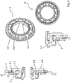
- FIG. 2 shows a first embodiment of the braking means 8.
- This has two arms 8.2, at the end of each a blocking element is 8.1.
- this blocking element acts 8.1 blocking between a projection 5.1 of the eccentric 5 and a locking contour, here a fixing ring 13, which is provided in the present case on the gear 4 or integral with the gear 4, so together that Doublestell kit F not to a movement of Exzenters can lead relatively, for example, to the gear 4 or another part of the adjustment.
- a blocking element 8.1 acts blocking only in one direction of rotation.
- the arms 8.2 are biased in the present case, so that they bias the blocking elements 8.1 respectively in the direction of the locking contour 13, in one of its recesses.
- FIG. 3 shows a specific embodiment of the locking means according to FIG. 2 ,
- the brake means 8 only an arm 8.2.
- a radial arm 8.4 is provided, which does not cooperate with the unlocking 9.1 and which allows an overstroke to avoid rattling noises when turning the adjustment.
Landscapes
- Engineering & Computer Science (AREA)
- Mechanical Engineering (AREA)
- Aviation & Aerospace Engineering (AREA)
- Transportation (AREA)
- Chairs For Special Purposes, Such As Reclining Chairs (AREA)
- Seats For Vehicles (AREA)
Description
- Die vorliegende Erfindung betrifft eine Verstellvorrichtung für eine Fahrzeugkomponente, insbesondere für die Rückenlehne eines Fahrzeugsitzes mit einem ersten und einem zweiten Beschlagteil, die entlang einer Drehachse angeordnet sind, wobei die relative Lage der beiden Beschlagteile zueinander veränderbar ist, wobei ein Drehmoment von einem Antrieb auf ein Zahnrad übertragen wird, das an dem zweiten Beschlagteil abrollt und dadurch das zweite Beschlagteil verstellt. Des Weiteren betrifft die vorliegende Erfindung ein Zahnrad einer Verstellvorrichtung einer Fahrzeugkomponente, insbesondere der Rückenlehne eines Kraftfahrzeugsitzes.
- Derartige Verstellvorrichtungen, die im Fahrzeugbau beispielsweise auch als Recliner bezeichnet werden, sind aus dem Stand der Technik hinlänglich bekannt. Beispielsweise offenbart
WO 2010/102413 A1 einen Scheiben-Recliner, Bei diesen Verstellvorrichtungen besteht jedoch der Nachteil, dass sie sich durch Abnutzung und/oder Vibration selbst verstellen, was unerwünscht ist. - Es war deshalb die Aufgabe der vorliegenden Erfindung, eine Verstellvorrichtung zur Verfügung zu stellen, die die Nachteile des Standes der Technik nicht aufweist.
- Gelöst wird die Aufgabe mit einer Verstellvorrichtung für eine Fahrzeugkomponente, insbesondere für die Rückenlehne eines Fahrzeugsitzes, gemäß Anspruch 1.
- Vorzugsweise weist das Bremsmittel mindestens einen, vorzugsweise zwei Arme auf, der/die insbesondere federnd vorgesehen ist/sind. Jeder Arm weist an seinem einen Ende vorzugsweise ein Blockierelement auf, das verhindert, dass sich der Exzenter selbsttätig relativ zu der Verriegelungskontur, die an dem Zahnrad vorgesehen ist, oder einem anderen Teil der Verstellvorrichtung verstellt. Jedes Blockierelement wirkt kraft- und/oder formschlüssig mit der Verriegelungskontur vorzugsweise in einer Vielzahl von unterschiedlichen Stellungen verriegelnd zusammen. Das Bremsmittel verhindert selbsttätige Verstellungen vorzugsweise in beide Drehrichtungen, wobei ein Blockierelement vorzugsweise nur in eine Drehrichtung blockiert. Die Verriegelungskontur weist vorzugsweise eine Vielzahl von Kraft- und/oder Formschlussmitteln, beispielsweise Zähnen oder zahnähnlichen Strukturen, auf, die vorzugsweise äquidistant angeordnet sind. Vorzugsweise ist die Verriegelungskontur kreisringförmig angeordnet.
- Vorzugsweise ist jeder Arm elastisch so vorgespannt, dass er das Blockierelement gegen beispielsweise die Verriegelungskontur oder ein anderes Element des Recliners drückt.
- Weiterhin bevorzugt weist der Arm eine Rampe auf, die beispielsweise mit einem Antriebsmittel zusammenwirkt und dadurch das Bremsmittel wahlweise entriegelt, insbesondere, indem der Arm des Bremsmittels gegen seine Vorspannrichtung elastisch verformt wird.
- Vorzugsweise ist die Verriegelungskontur im Bereich des inneren Durchmessers des Zahnrades vorgesehen. Besonders bevorzugt ist die Verriegelungskontur kraft- und/oder stoffschlüssig mit dem Zahnrad verbunden. Vorzugsweise ist die Verriegelungskontur einstückig mit dem Zahnrad vorgesehen. Vorzugsweise oder erfindungsgemäß weist das Zahnrad insbesondere an seinem inneren Umfang eine Verriegelungskontur, beispielsweise Einbuchtungen, auf, mit denen das Blockierelement des Bremsmittels blockierend zusammen wirken kann.
- , Gemäß einer Ausführungsform der Erfindung ist die axiale Erstreckung des Lagers des Zahnrades größer als die axiale Erstreckung der Zähne des Zahnrades. Dadurch wird die Lagerung des Zahnrades stabiler.
- Gemäß einer weiteren Ausführungsform der vorliegenden Erfindung weist das Zahnrad eine Dichtfläche auf. Durch diese Dichtfläche wird verhindert, dass Dreck, Farbe oder Flüssigkeit in die Verstellvorrichtung gelangt. Vorzugsweise ist die Dichtfläche in radialer Richtung vorgesehen.
- Vorzugsweise wirkt die Dichtfläche dichtend mit einer Abdeckung und/oder dem Antriebsmittel der erfindungsgemäßen Verstellvorrichtung zusammen.
- Im Folgenden wird die Erfindung anhand der
Figuren 1 - 4 erläutert. Diese Erläuterungen sind lediglich beispielhaft und gelten für alle Erfindungen gleichermaßen. - Figur 1
- zeigt eine Explosionszeichnung der erfindungsgemäßen Verstelleinrichtung.
- Figur 2
- zeigt das Bremsmittel.
- Figur 3
- zeigt eine weitere Ausführungsform des Bremsmittels.
-
Figur 1 zeigt eine Explosionszeichnung einer Ausführungsform der erfindungsgemäßen Verstelleinrichtung. Die Verstelleinrichtung weist ein erstes Beschlagteil 2, den Sitzteiladapter, und ein zweites Beschlagteil 3, den Lehenadapter, auf, das direkt oder indirekt mit der Lehne des Fahrzeugsitzes verbunden ist. Der Sitzadapter 2 ist an dem Fahrzeugsitz befestigt, hier verschraubt. An dem Sitzadapter 2 ist drehbar ein Zahnrad 4 mit einer Außenverzahnung vorgesehen, die mit der Verzahnung des Lehenadapters kämmend zusammenwirkt und dadurch den Lehnenadapter winkelverstellt. Der Lehnenadapter 3 wird mit der Rückenlehne des Fahrzeugsitzes verbunden, vorzugsweise verschweißt. Der Fachmann erkennt, dass diese Funktionalitäten der beiden Adapter 2 und 3 auch vertauscht sein können. Die relative Lage des Lehnenadapters 3 relativ zum Sitzadapter 2 wird mittels eines Exzenters verändert, der zwei Keile 5 aufweist. Diese beiden Keile 5 sind bevorzugt symmetrisch und besonders bevorzugt spiegelsymmetrisch zu einer durch die Drehachse D verlaufenden Ebene angeordnet. Die beiden Keile 5 werden mit einem Kraftspeicher, hier einer Feder 7, vorzugsweise einer Ringfeder, deren Enden jeweils in eine Kerbe in den Keilen 5 eingreifen, auseinandergedrückt. Der Kraftspeicher 7 ist Teil des Exzenters. Außerdem sind die Keile 5 vorzugsweise zumindest teilweise in einer Lagerschale 6 angeordnet und stützen sich an dieser ab. Durch die Lagerschale 6 kann die Reibung zwischen dem Exzenter und dem Zahnrad 4 reduziert und ein gleichmäßiger Rundlauf des Exzenters erzielt werden. Des Weiteren weist die erfindungsgemäße Vorrichtung ein Antriebsmittel 9, auf, das manuell oder motorisch angetrieben wird. Dieses Antriebsmittel 9 überträgt seine Drehbewegung auf den Exzenter 5, so dass beim Drehen des Antriebes 9 das Zahnrad 4 in dem innenverzahnten Lehnenadapter 3 abrollt. - Der Exzenter dient, wie bereits erwähnt, zum Antrieb des außenverzahnten Zahnrades 4 innerhalb eines innenverzahnten, mindestens einen Zahn mehr aufweisenden, äußeren Zahnkranzes. Es handelt sich demnach vorzugsweise um ein sogenanntes Taumelgetriebe.
- Erfindungsgemäß weist die Vorrichtung ein Bremsmittel 8 auf, das verhindert, das sich das erste Beschlagteil 2 relativ zum zweiten Beschlagteil 3 selbsttätig verstellt, d.h. ohne dass das Antriebsmittel 9 betätigt wird.
-
Figur 2 zeigt eine erste Ausführung des Bremsmittels 8. Dieses weist zwei Arme 8.2 auf, an deren Ende sich jeweils ein Blockierelement 8.1 befindet. Wie insbesondereFigur 2b entnommen werden kann, wirkt dieses Blockierelement 8.1 blockierend zwischen einem Vorsprung 5.1 des Exzenterantriebs 5 und einer Verriegelungskontur, hier einem Fixierring 13, die in dem vorliegenden Fall an dem Zahnrad 4 oder einstückig mit dem Zahnrad 4 vorgesehen ist, so zusammen, dass Selbstverstellkräfte F nicht zu einer Bewegung des Exzenters relativ beispielsweise zu dem Zahnrad 4 oder einem anderen Teil der Verstellvorrichtung führen können. Vorzugsweise wirkt ein Blockierelement 8.1 jeweils nur in eine Drehrichtung blockierend. Die Arme 8.2 sind in dem vorliegenden Fall vorgespannt, so dass sie die Blockierelemente 8.1 jeweils in Richtung der Verriegelungskontur 13, in eine von dessen Ausnehmungen, vorspannen. InFigur 2c ist die Entriegelung des Bremsmittels 8 dargestellt. Sobald das Antriebsmittel 9, wie beispielsweise durch den Pfeil 14 dargestellt ist, gedreht wird, wirkt jeweils ein Entriegelungsmittel 9.1 mit jeweils einer Entriegelungsrampe 8.3, die an dem Armen 8.2 vorgesehen, hier plastisch eingeformt, ist, so zusammen, dass der Arme 8.2 radial nach innen gedrückt wird und somit das Blockierelement 8.1 außer Eingriff mit dem Fixierring 13 gelangt. Somit kann die Verstellvorrichtung mittels des Antriebsmittels 9 in beide Drehrichtungen verstellt werden. -
Figur 3 zeigt eine spezielle Ausführungsform des Verriegelungsmittels gemäßFigur 2 . Im vorliegenden Fall weist das Bremsmittel 8 lediglich einen Arm 8.2 auf. An der anderen Seite des Bremsmittels 8 ist ein radialer Arm 8.4 vorgesehen, der nicht mit den Entriegelungsflächen 9.1 zusammenwirk und der einen Überhub erlaubt um Ratsch-Geräusche beim Verdrehen der Verstelleinrichtung zu vermeiden. -
- 1
- Verstellvorrichtung
- 2
- erstes Beschlagsteil, Sitzteil-Adapter
- 3
- zweites Beschlagteil
- 4
- Zahnrad
- 5
- Exzenter, Keilsegment
- 5.1
- Vorsprung
- 6
- Gleitlager
- 7
- Federmittel
- 8
- Bremsmittel
- 8.1
- Blockierelement
- 8.2
- Arm, Federmittel
- 8.3
- Rampe
- 8.4
- radialer Arm
- 9
- Antriebsmittel
- 9.1
- Entriegelungsmittel, Entriegelungsfläche
- 10
- Halteplatte
- 11
- Verriegelungskontur, Fixierring
- 12
- Haltering
- 13
- Verriegelungskontur, Fixierring
- 14
- Pfeil
- 15
- Übertragungsmittel, Drehmomentübertragungsmitttel
- 15.1
- Rampe
- D
- Drehachse
- F
- Selbstverstellungskräfte
Claims (9)
- Verstellvorrichtung für eine Fahrzeugkomponente, insbesondere für die Rückenlehne eines Fahrzeugsitzes, mit einem ersten Beschlagteil (2) und einem zweiten Beschlagteil (3), die entlang einer Drehachse (D) angeordnet sind, wobei die relative Lage der beiden Beschlagteile (2, 3) zueinander mittels eines Exzenters (5) veränderbar ist, der ein Drehmoment von einem Antrieb (9) auf ein Zahnrad (4) überträgt, so dass dieses an dem zweiten Beschlagteil (3) abrollt und der vorzugsweise zwei Exzentermittel (5.1) umfasst, wobei die Verstellvorrichtung ein Bremsmittel (8) aufweist, das deren Selbstverstellung zumindest weitgehend verhindert, wobei das Bremsmittel (8) mit einer Verriegelungskontur (4.2, 11, 13), die an dem Zahnrad (4) vorgesehen ist, zusammenwirkt, dadurch gekennzeichnet, dass das Bremsmittel nur einen Arm aufweist, an dessen Ende ein Blockierelement vorgesehen ist.
- Verstellvorrichtung nach Anspruch 1, dadurch gekennzeichnet, dass die Verriegelungskontur (4.2, 11, 13) im Bereich des inneren Durchmessers des Zahnrades vorgesehen ist.
- Verstellvorrichtung nach einem der voranstehenden Ansprüche, dadurch gekennzeichnet, dass die Verriegelungskontur (4.2, 11, 13) kraft- und/oder stoffschlüssig mit dem Zahnrad (4) verbunden ist.
- Verstellvorrichtung nach einem der Ansprüche 1 - 3, dadurch gekennzeichnet, dass die Verriegelungskontur (4.2, 11, 13) einstückig mit dem Zahnrad (4) vorgesehen ist.
- Verstellvorrichtung nach einem der Ansprüche 3 - 4, dadurch gekennzeichnet, dass jeder Arm eine Rampe aufweist, die beispielsweise mit einem Antriebsmittel zusammenwirkt und dadurch das Bremsmittel wahlweise entriegelt.
- Verstellvorrichtung nach einem der voranstehenden Ansprüche, dadurch gekennzeichnet, dass die axiale Erstreckung des Lagers des Zahnrades größer ist als die axiale Erstreckung der Zähne des Zahnrades.
- Verstellvorrichtung nach Anspruch 6, dadurch gekennzeichnet, dass das Zahnrad (4) eine Dichtfläche (4.4) aufweist.
- Verstellvorrichtung nach Anspruch 7, dadurch gekennzeichnet, dass die Dichtfläche in radialer Richtung vorgesehen ist.
- Verstellvorrichtung nach einem der Ansprüche 7 oder 8, dadurch gekennzeichnet, dass die Dichtfläche (4.4) dichtend mit einer Abdeckung und/oder dem Antriebsmittel zusammenwirkt.
Applications Claiming Priority (2)
| Application Number | Priority Date | Filing Date | Title |
|---|---|---|---|
| DE102010051401 | 2010-11-16 | ||
| PCT/EP2011/005762 WO2012065721A1 (de) | 2010-11-16 | 2011-11-16 | Verstellvorrichtung eines fahrzeugsitzes mit einer selbstverstellbremse |
Publications (2)
| Publication Number | Publication Date |
|---|---|
| EP2640600A1 EP2640600A1 (de) | 2013-09-25 |
| EP2640600B1 true EP2640600B1 (de) | 2017-03-01 |
Family
ID=45093671
Family Applications (1)
| Application Number | Title | Priority Date | Filing Date |
|---|---|---|---|
| EP11790869.9A Not-in-force EP2640600B1 (de) | 2010-11-16 | 2011-11-16 | Verstellvorrichtung eines fahrzeugsitzes mit einer selbstverstellbremse |
Country Status (6)
| Country | Link |
|---|---|
| US (1) | US9016153B2 (de) |
| EP (1) | EP2640600B1 (de) |
| JP (1) | JP5696223B2 (de) |
| KR (1) | KR101436944B1 (de) |
| CN (1) | CN103313874B (de) |
| WO (1) | WO2012065721A1 (de) |
Cited By (1)
| Publication number | Priority date | Publication date | Assignee | Title |
|---|---|---|---|---|
| US11001173B2 (en) * | 2018-04-18 | 2021-05-11 | Martur Italy S.R.L. | Reclining device for a vehicle seat |
Families Citing this family (8)
| Publication number | Priority date | Publication date | Assignee | Title |
|---|---|---|---|---|
| CN103129418B (zh) * | 2011-11-25 | 2015-03-25 | 湖北中航精机科技有限公司 | 一种座椅调角器及其座椅 |
| FR3006637B1 (fr) * | 2013-06-10 | 2015-07-17 | Faurecia Sieges Automobile | Mecanisme d'articulation et siege de vehicule comportant un tel mecanisme |
| DE102014207529A1 (de) * | 2014-01-07 | 2015-07-09 | Johnson Controls Gmbh | Fahrzeugsitz mit einer antriebsvorrichtung und verfahren zur spielfreien anbindung einer antriebsvorrichtung |
| DE102016225834B4 (de) * | 2016-10-04 | 2020-01-09 | Adient Luxembourg Holding S.À R.L. | Fahrzeugsitz, insbesondere kraftfahrzeugsitz |
| MA52825B1 (fr) | 2018-09-25 | 2021-09-30 | Martur Italy Srl | Dispositif d'inclinaison pour un siège de véhicule |
| CN113939428B (zh) | 2019-05-10 | 2023-09-22 | 恺博座椅机械部件有限公司 | 用于车辆座椅的调节配件 |
| EP3966070B1 (de) | 2019-05-10 | 2024-05-01 | KEIPER Seating Mechanisms Co., Ltd. | Einstellbeschlag für einen fahrzeugsitz, sowie fahrzeugsitz |
| WO2022054025A1 (en) | 2020-09-14 | 2022-03-17 | Keiper Seating Mechanisms Co., Ltd. | Adjustment fitting for a vehicle seat, and vehicle seat |
Family Cites Families (11)
| Publication number | Priority date | Publication date | Assignee | Title |
|---|---|---|---|---|
| DE19500914A1 (de) * | 1995-01-13 | 1996-07-18 | Hammerstein Gmbh C Rob | Taumelgelenkbeschlag für einen verstellbaren Fahrzeugsitz |
| DE19548809C1 (de) | 1995-12-27 | 1997-05-22 | Keiper Recaro Gmbh Co | Ver- und Feststelleinrichtung für Sitze, wie Kraftfahrzeugsitze, zur Verstellung der Rückenlehne |
| WO2002064397A1 (de) * | 2001-02-12 | 2002-08-22 | Volkswagen Aktiengesellschaft | Verstelleinrichtung zur drehverstellung zweier zentrisch gelagerter adapterstücke, insbesondere für einen sitz vorzugsweise eines kraftfahrzeuges, und planetengetriebe hierfür |
| DE102004007043B3 (de) | 2004-02-12 | 2005-06-23 | Keiper Gmbh & Co. Kg | Beschlag für einen Fahrzeugsitz |
| DE102004050152A1 (de) * | 2004-10-15 | 2006-04-20 | Keiper Gmbh & Co.Kg | Getriebebeschlag für einen Fahrzeugsitz |
| US8292367B2 (en) * | 2006-09-26 | 2012-10-23 | Das Corporation | Pumping device for seat cushion of vehicle |
| DE102007007362B4 (de) * | 2007-02-14 | 2009-07-09 | Faurecia Autositze Gmbh | Verstellmechanismus |
| US8746796B2 (en) * | 2009-03-12 | 2014-06-10 | Magna Seating Inc. | Anti-backdrive for continuous disc recliner |
| CN101941389B (zh) * | 2009-07-04 | 2012-06-20 | 湖北中航精机科技股份有限公司 | 座椅调角器及具有该调角器的座椅 |
| DE102009039461B4 (de) * | 2009-08-26 | 2014-10-09 | Johnson Controls Components Gmbh & Co. Kg | Beschlag für einen Fahrzeugsitz |
| JP5648133B2 (ja) * | 2010-11-17 | 2015-01-07 | ジョンソン コントロールズ メタルズ アンド メカニズムス ゲーエムベーハー アンド カンパニー カーゲー | 車両シートの調節装置用自動ロック段階的切替機構 |
-
2011
- 2011-11-16 JP JP2013539162A patent/JP5696223B2/ja not_active Expired - Fee Related
- 2011-11-16 US US13/885,613 patent/US9016153B2/en active Active
- 2011-11-16 KR KR1020137015465A patent/KR101436944B1/ko not_active Expired - Fee Related
- 2011-11-16 WO PCT/EP2011/005762 patent/WO2012065721A1/de not_active Ceased
- 2011-11-16 CN CN201180055127.8A patent/CN103313874B/zh active Active
- 2011-11-16 EP EP11790869.9A patent/EP2640600B1/de not_active Not-in-force
Non-Patent Citations (1)
| Title |
|---|
| None * |
Cited By (1)
| Publication number | Priority date | Publication date | Assignee | Title |
|---|---|---|---|---|
| US11001173B2 (en) * | 2018-04-18 | 2021-05-11 | Martur Italy S.R.L. | Reclining device for a vehicle seat |
Also Published As
| Publication number | Publication date |
|---|---|
| CN103313874A (zh) | 2013-09-18 |
| KR20130082168A (ko) | 2013-07-18 |
| WO2012065721A1 (de) | 2012-05-24 |
| JP2013544147A (ja) | 2013-12-12 |
| JP5696223B2 (ja) | 2015-04-08 |
| US20130319144A1 (en) | 2013-12-05 |
| EP2640600A1 (de) | 2013-09-25 |
| CN103313874B (zh) | 2016-01-06 |
| US9016153B2 (en) | 2015-04-28 |
| KR101436944B1 (ko) | 2014-09-02 |
Similar Documents
| Publication | Publication Date | Title |
|---|---|---|
| DE102010012980B4 (de) | Beschlag für einen Fahrzeugsitz und Fahrzeugsitz | |
| EP2640600A1 (de) | Verstellvorrichtung eines fahrzeugsitzes mit einer selbstverstellbremse | |
| DE102010062414B4 (de) | Taumelgelenkbeschlag für eine Verstellvorrichtung eines Kraftfahrzeugsitzes, insbesondere für einen Rückenlehnengelenkbeschlag | |
| EP2525995B1 (de) | Beschlagsystem für einen fahrzeugsitz | |
| WO2012136315A1 (de) | Elektromechanische servolenkung mit spielausgleich für das schneckenradgetriebe | |
| DE102015010348A1 (de) | Vorrichtung zur Befestigung eines Verschleißsensors an einem Bremshebel einer Fahrzeugbremse | |
| EP2958769A1 (de) | Beschlag für einen fahrzeugsitz, verfahren zur montage eines beschlags für einen fahrzeugsitz sowie fahrzeugsitz | |
| DE202008005523U1 (de) | Beschlag für einen Fahrzeugsitz | |
| DE102009038735B4 (de) | Verstellvorrichtung für eine Fahrzeugkomponente | |
| EP1189784B1 (de) | Neigungsverstellbeschlag für die rückenlehne eines kraftfahrzeugsitzes | |
| EP2748028B1 (de) | Verstellbeschlag mit einem axialsperrsystem zur ablaufsicherung | |
| DE102012012852A1 (de) | Beschlag für einen Fahrzeugsitz sowie Fahrzeugsitz | |
| EP2580086B1 (de) | Beschlag für einen fahrzeugsitz | |
| DE69704202T2 (de) | Neigungsverstellungsmechanismus für einen Sitz | |
| DE10134355A1 (de) | Verstellbeschlag für Kraftfahrzeugsitze | |
| WO2012136341A2 (de) | Beschlag für einen fahrzeugsitz | |
| EP3779229A1 (de) | Kupplungsring | |
| DE102011113748B4 (de) | Verfahren zur Herstellung eines Fahrzeugsitz-Beschlags | |
| DE102012006059A1 (de) | Verstellvorrichtung und Verfahren zum Verstellen einer Kraftfahrzeugkomponente | |
| DE202015104504U1 (de) | Anhängerkupplung | |
| EP3106698A1 (de) | Mechanisches getriebe mit integrierter lastmomentsperre | |
| EP2993076B1 (de) | Beschlag und fahrzeugsitz | |
| WO2019072463A1 (de) | Getriebe mit planetenelement und führungsbahn | |
| EP0283875A2 (de) | Walzendynamo | |
| EP3765758B1 (de) | Schneckengetriebe mit einem schwenklager mit definierter schwenkachse |
Legal Events
| Date | Code | Title | Description |
|---|---|---|---|
| PUAI | Public reference made under article 153(3) epc to a published international application that has entered the european phase |
Free format text: ORIGINAL CODE: 0009012 |
|
| 17P | Request for examination filed |
Effective date: 20130617 |
|
| AK | Designated contracting states |
Kind code of ref document: A1 Designated state(s): AL AT BE BG CH CY CZ DE DK EE ES FI FR GB GR HR HU IE IS IT LI LT LU LV MC MK MT NL NO PL PT RO RS SE SI SK SM TR |
|
| DAX | Request for extension of the european patent (deleted) | ||
| 17Q | First examination report despatched |
Effective date: 20151030 |
|
| GRAP | Despatch of communication of intention to grant a patent |
Free format text: ORIGINAL CODE: EPIDOSNIGR1 |
|
| INTG | Intention to grant announced |
Effective date: 20160719 |
|
| GRAJ | Information related to disapproval of communication of intention to grant by the applicant or resumption of examination proceedings by the epo deleted |
Free format text: ORIGINAL CODE: EPIDOSDIGR1 |
|
| GRAP | Despatch of communication of intention to grant a patent |
Free format text: ORIGINAL CODE: EPIDOSNIGR1 |
|
| INTC | Intention to grant announced (deleted) | ||
| INTG | Intention to grant announced |
Effective date: 20161115 |
|
| GRAS | Grant fee paid |
Free format text: ORIGINAL CODE: EPIDOSNIGR3 |
|
| GRAA | (expected) grant |
Free format text: ORIGINAL CODE: 0009210 |
|
| AK | Designated contracting states |
Kind code of ref document: B1 Designated state(s): AL AT BE BG CH CY CZ DE DK EE ES FI FR GB GR HR HU IE IS IT LI LT LU LV MC MK MT NL NO PL PT RO RS SE SI SK SM TR |
|
| REG | Reference to a national code |
Ref country code: GB Ref legal event code: FG4D Free format text: NOT ENGLISH |
|
| REG | Reference to a national code |
Ref country code: CH Ref legal event code: EP Ref country code: AT Ref legal event code: REF Ref document number: 870853 Country of ref document: AT Kind code of ref document: T Effective date: 20170315 |
|
| REG | Reference to a national code |
Ref country code: IE Ref legal event code: FG4D Free format text: LANGUAGE OF EP DOCUMENT: GERMAN |
|
| REG | Reference to a national code |
Ref country code: DE Ref legal event code: R096 Ref document number: 502011011760 Country of ref document: DE |
|
| REG | Reference to a national code |
Ref country code: NL Ref legal event code: MP Effective date: 20170301 |
|
| REG | Reference to a national code |
Ref country code: LT Ref legal event code: MG4D |
|
| PG25 | Lapsed in a contracting state [announced via postgrant information from national office to epo] |
Ref country code: GR Free format text: LAPSE BECAUSE OF FAILURE TO SUBMIT A TRANSLATION OF THE DESCRIPTION OR TO PAY THE FEE WITHIN THE PRESCRIBED TIME-LIMIT Effective date: 20170602 Ref country code: LT Free format text: LAPSE BECAUSE OF FAILURE TO SUBMIT A TRANSLATION OF THE DESCRIPTION OR TO PAY THE FEE WITHIN THE PRESCRIBED TIME-LIMIT Effective date: 20170301 Ref country code: FI Free format text: LAPSE BECAUSE OF FAILURE TO SUBMIT A TRANSLATION OF THE DESCRIPTION OR TO PAY THE FEE WITHIN THE PRESCRIBED TIME-LIMIT Effective date: 20170301 Ref country code: HR Free format text: LAPSE BECAUSE OF FAILURE TO SUBMIT A TRANSLATION OF THE DESCRIPTION OR TO PAY THE FEE WITHIN THE PRESCRIBED TIME-LIMIT Effective date: 20170301 Ref country code: NO Free format text: LAPSE BECAUSE OF FAILURE TO SUBMIT A TRANSLATION OF THE DESCRIPTION OR TO PAY THE FEE WITHIN THE PRESCRIBED TIME-LIMIT Effective date: 20170601 |
|
| PG25 | Lapsed in a contracting state [announced via postgrant information from national office to epo] |
Ref country code: SE Free format text: LAPSE BECAUSE OF FAILURE TO SUBMIT A TRANSLATION OF THE DESCRIPTION OR TO PAY THE FEE WITHIN THE PRESCRIBED TIME-LIMIT Effective date: 20170301 Ref country code: RS Free format text: LAPSE BECAUSE OF FAILURE TO SUBMIT A TRANSLATION OF THE DESCRIPTION OR TO PAY THE FEE WITHIN THE PRESCRIBED TIME-LIMIT Effective date: 20170301 Ref country code: ES Free format text: LAPSE BECAUSE OF FAILURE TO SUBMIT A TRANSLATION OF THE DESCRIPTION OR TO PAY THE FEE WITHIN THE PRESCRIBED TIME-LIMIT Effective date: 20170301 Ref country code: LV Free format text: LAPSE BECAUSE OF FAILURE TO SUBMIT A TRANSLATION OF THE DESCRIPTION OR TO PAY THE FEE WITHIN THE PRESCRIBED TIME-LIMIT Effective date: 20170301 Ref country code: BG Free format text: LAPSE BECAUSE OF FAILURE TO SUBMIT A TRANSLATION OF THE DESCRIPTION OR TO PAY THE FEE WITHIN THE PRESCRIBED TIME-LIMIT Effective date: 20170601 |
|
| PG25 | Lapsed in a contracting state [announced via postgrant information from national office to epo] |
Ref country code: NL Free format text: LAPSE BECAUSE OF FAILURE TO SUBMIT A TRANSLATION OF THE DESCRIPTION OR TO PAY THE FEE WITHIN THE PRESCRIBED TIME-LIMIT Effective date: 20170301 |
|
| PG25 | Lapsed in a contracting state [announced via postgrant information from national office to epo] |
Ref country code: CZ Free format text: LAPSE BECAUSE OF FAILURE TO SUBMIT A TRANSLATION OF THE DESCRIPTION OR TO PAY THE FEE WITHIN THE PRESCRIBED TIME-LIMIT Effective date: 20170301 Ref country code: RO Free format text: LAPSE BECAUSE OF FAILURE TO SUBMIT A TRANSLATION OF THE DESCRIPTION OR TO PAY THE FEE WITHIN THE PRESCRIBED TIME-LIMIT Effective date: 20170301 Ref country code: EE Free format text: LAPSE BECAUSE OF FAILURE TO SUBMIT A TRANSLATION OF THE DESCRIPTION OR TO PAY THE FEE WITHIN THE PRESCRIBED TIME-LIMIT Effective date: 20170301 Ref country code: SK Free format text: LAPSE BECAUSE OF FAILURE TO SUBMIT A TRANSLATION OF THE DESCRIPTION OR TO PAY THE FEE WITHIN THE PRESCRIBED TIME-LIMIT Effective date: 20170301 Ref country code: IT Free format text: LAPSE BECAUSE OF FAILURE TO SUBMIT A TRANSLATION OF THE DESCRIPTION OR TO PAY THE FEE WITHIN THE PRESCRIBED TIME-LIMIT Effective date: 20170301 |
|
| PG25 | Lapsed in a contracting state [announced via postgrant information from national office to epo] |
Ref country code: IS Free format text: LAPSE BECAUSE OF FAILURE TO SUBMIT A TRANSLATION OF THE DESCRIPTION OR TO PAY THE FEE WITHIN THE PRESCRIBED TIME-LIMIT Effective date: 20170701 Ref country code: SM Free format text: LAPSE BECAUSE OF FAILURE TO SUBMIT A TRANSLATION OF THE DESCRIPTION OR TO PAY THE FEE WITHIN THE PRESCRIBED TIME-LIMIT Effective date: 20170301 Ref country code: PT Free format text: LAPSE BECAUSE OF FAILURE TO SUBMIT A TRANSLATION OF THE DESCRIPTION OR TO PAY THE FEE WITHIN THE PRESCRIBED TIME-LIMIT Effective date: 20170703 Ref country code: PL Free format text: LAPSE BECAUSE OF FAILURE TO SUBMIT A TRANSLATION OF THE DESCRIPTION OR TO PAY THE FEE WITHIN THE PRESCRIBED TIME-LIMIT Effective date: 20170301 |
|
| REG | Reference to a national code |
Ref country code: DE Ref legal event code: R097 Ref document number: 502011011760 Country of ref document: DE |
|
| PLBE | No opposition filed within time limit |
Free format text: ORIGINAL CODE: 0009261 |
|
| STAA | Information on the status of an ep patent application or granted ep patent |
Free format text: STATUS: NO OPPOSITION FILED WITHIN TIME LIMIT |
|
| PG25 | Lapsed in a contracting state [announced via postgrant information from national office to epo] |
Ref country code: DK Free format text: LAPSE BECAUSE OF FAILURE TO SUBMIT A TRANSLATION OF THE DESCRIPTION OR TO PAY THE FEE WITHIN THE PRESCRIBED TIME-LIMIT Effective date: 20170301 |
|
| 26N | No opposition filed |
Effective date: 20171204 |
|
| PG25 | Lapsed in a contracting state [announced via postgrant information from national office to epo] |
Ref country code: SI Free format text: LAPSE BECAUSE OF FAILURE TO SUBMIT A TRANSLATION OF THE DESCRIPTION OR TO PAY THE FEE WITHIN THE PRESCRIBED TIME-LIMIT Effective date: 20170301 |
|
| REG | Reference to a national code |
Ref country code: DE Ref legal event code: R119 Ref document number: 502011011760 Country of ref document: DE |
|
| PG25 | Lapsed in a contracting state [announced via postgrant information from national office to epo] |
Ref country code: MC Free format text: LAPSE BECAUSE OF FAILURE TO SUBMIT A TRANSLATION OF THE DESCRIPTION OR TO PAY THE FEE WITHIN THE PRESCRIBED TIME-LIMIT Effective date: 20170301 |
|
| GBPC | Gb: european patent ceased through non-payment of renewal fee |
Effective date: 20171116 |
|
| PG25 | Lapsed in a contracting state [announced via postgrant information from national office to epo] |
Ref country code: CH Free format text: LAPSE BECAUSE OF NON-PAYMENT OF DUE FEES Effective date: 20171130 Ref country code: LI Free format text: LAPSE BECAUSE OF NON-PAYMENT OF DUE FEES Effective date: 20171130 |
|
| PG25 | Lapsed in a contracting state [announced via postgrant information from national office to epo] |
Ref country code: LU Free format text: LAPSE BECAUSE OF NON-PAYMENT OF DUE FEES Effective date: 20171116 |
|
| REG | Reference to a national code |
Ref country code: FR Ref legal event code: ST Effective date: 20180731 Ref country code: BE Ref legal event code: MM Effective date: 20171130 |
|
| REG | Reference to a national code |
Ref country code: IE Ref legal event code: MM4A |
|
| PG25 | Lapsed in a contracting state [announced via postgrant information from national office to epo] |
Ref country code: MT Free format text: LAPSE BECAUSE OF FAILURE TO SUBMIT A TRANSLATION OF THE DESCRIPTION OR TO PAY THE FEE WITHIN THE PRESCRIBED TIME-LIMIT Effective date: 20170301 |
|
| PG25 | Lapsed in a contracting state [announced via postgrant information from national office to epo] |
Ref country code: FR Free format text: LAPSE BECAUSE OF NON-PAYMENT OF DUE FEES Effective date: 20171130 Ref country code: DE Free format text: LAPSE BECAUSE OF NON-PAYMENT OF DUE FEES Effective date: 20180602 Ref country code: IE Free format text: LAPSE BECAUSE OF NON-PAYMENT OF DUE FEES Effective date: 20171116 |
|
| PG25 | Lapsed in a contracting state [announced via postgrant information from national office to epo] |
Ref country code: GB Free format text: LAPSE BECAUSE OF NON-PAYMENT OF DUE FEES Effective date: 20171116 Ref country code: BE Free format text: LAPSE BECAUSE OF NON-PAYMENT OF DUE FEES Effective date: 20171130 |
|
| REG | Reference to a national code |
Ref country code: AT Ref legal event code: MM01 Ref document number: 870853 Country of ref document: AT Kind code of ref document: T Effective date: 20171116 |
|
| PG25 | Lapsed in a contracting state [announced via postgrant information from national office to epo] |
Ref country code: AT Free format text: LAPSE BECAUSE OF NON-PAYMENT OF DUE FEES Effective date: 20171116 |
|
| PG25 | Lapsed in a contracting state [announced via postgrant information from national office to epo] |
Ref country code: HU Free format text: LAPSE BECAUSE OF FAILURE TO SUBMIT A TRANSLATION OF THE DESCRIPTION OR TO PAY THE FEE WITHIN THE PRESCRIBED TIME-LIMIT; INVALID AB INITIO Effective date: 20111116 |
|
| PG25 | Lapsed in a contracting state [announced via postgrant information from national office to epo] |
Ref country code: CY Free format text: LAPSE BECAUSE OF NON-PAYMENT OF DUE FEES Effective date: 20170301 |
|
| PG25 | Lapsed in a contracting state [announced via postgrant information from national office to epo] |
Ref country code: MK Free format text: LAPSE BECAUSE OF FAILURE TO SUBMIT A TRANSLATION OF THE DESCRIPTION OR TO PAY THE FEE WITHIN THE PRESCRIBED TIME-LIMIT Effective date: 20170301 |
|
| PG25 | Lapsed in a contracting state [announced via postgrant information from national office to epo] |
Ref country code: TR Free format text: LAPSE BECAUSE OF FAILURE TO SUBMIT A TRANSLATION OF THE DESCRIPTION OR TO PAY THE FEE WITHIN THE PRESCRIBED TIME-LIMIT Effective date: 20170301 |
|
| PG25 | Lapsed in a contracting state [announced via postgrant information from national office to epo] |
Ref country code: AL Free format text: LAPSE BECAUSE OF FAILURE TO SUBMIT A TRANSLATION OF THE DESCRIPTION OR TO PAY THE FEE WITHIN THE PRESCRIBED TIME-LIMIT Effective date: 20170301 |