EP2634332B1 - Lock for a window, door or similar - Google Patents
Lock for a window, door or similar Download PDFInfo
- Publication number
- EP2634332B1 EP2634332B1 EP12157899.1A EP12157899A EP2634332B1 EP 2634332 B1 EP2634332 B1 EP 2634332B1 EP 12157899 A EP12157899 A EP 12157899A EP 2634332 B1 EP2634332 B1 EP 2634332B1
- Authority
- EP
- European Patent Office
- Prior art keywords
- bolt
- drive
- latch
- state
- lock
- Prior art date
- Legal status (The legal status is an assumption and is not a legal conclusion. Google has not performed a legal analysis and makes no representation as to the accuracy of the status listed.)
- Not-in-force
Links
Images


Classifications
-
- E—FIXED CONSTRUCTIONS
- E05—LOCKS; KEYS; WINDOW OR DOOR FITTINGS; SAFES
- E05B—LOCKS; ACCESSORIES THEREFOR; HANDCUFFS
- E05B65/00—Locks or fastenings for special use
- E05B65/10—Locks or fastenings for special use for panic or emergency doors
- E05B65/1086—Locks with panic function, e.g. allowing opening from the inside without a ley even when locked from the outside
-
- E—FIXED CONSTRUCTIONS
- E05—LOCKS; KEYS; WINDOW OR DOOR FITTINGS; SAFES
- E05B—LOCKS; ACCESSORIES THEREFOR; HANDCUFFS
- E05B59/00—Locks with latches separate from the lock-bolts or with a plurality of latches or lock-bolts
-
- E—FIXED CONSTRUCTIONS
- E05—LOCKS; KEYS; WINDOW OR DOOR FITTINGS; SAFES
- E05B—LOCKS; ACCESSORIES THEREFOR; HANDCUFFS
- E05B63/00—Locks or fastenings with special structural characteristics
- E05B63/16—Locks or fastenings with special structural characteristics with the handles on opposite sides moving independently
Description
Die Erfindung betrifft ein Schloss für eine Tür, ein Fenster oder dergleichen,
- mit einem Riegel (8),
- mit einem inneren Riegelantrieb (4), der ein einer Rauminnenseite zugeordnetes inneres Riegel-Betätigungsorgan (6) sowie ein inneres Riegelgetriebe (7) zwischen dem inneren Riegel-Betätigungsorgan (6) und dem Riegel (8) aufweist und mittels dessen der Riegel (8) aus einem Verriegelungszustand in einen Entriegelungszustand überführbar ist,
- mit einem aktivierbaren und deaktivierbaren äußeren Riegelantrieb (5), der ein einer Raumaußenseite zugeordnetes äußeres Riegel-Betätigungsorgan (10) sowie ein äußeres Riegelgetriebe (11) zwischen dem äußeren Riegel-Betätigungsorgan (10) und dem Riegel (8) aufweist und für den eine betätigbare Schalteinrichtung (28) vorgesehen ist, durch deren Betätigen der aktivierte äußere Riegelantrieb (5) deaktivierbar ist, wobei der Riegel (8) mittels des aktivierten äußeren Riegelantriebs (5) aus einem Verriegelungszustand in einen Entriegelungszustand überführbar ist und wobei der deaktivierte äußere Riegelantrieb (5) mittels der Schalteinrichtung (28) gegen eine Überführung des Riegels (8) aus einem Verriegelungszustand in einen Entriegelungszustand gesperrt ist sowie
- mit wenigstens einem dem inneren Riegelgetriebe (7) und dem äußeren Riegelgetriebe (11) gemeinsamen Riegelgetriebeelement (3), welches zur Überführung des Riegels (8) aus einem Verriegelungszustand in einen Entriegelungszustand mittels des inneren Riegel-Betätigungsorgans (6) oder mittels des äußeren Riegel-Betätigungsorgans (10) mit einer Entriegelungsbewegung antreibbar ist,
- wobei der Riegel (8) bei deaktiviertem äußerem Riegelantrieb (5) mittels des inneren Riegel-Betätigungsorgans (6) aus einem Verriegelungszustand in einen Entriegelungszustand überführbar ist, indem der äußere Riegelantrieb (5) zwischen dem gemeinsamen Riegelgetriebeelement (3) und dem äußeren Riegel-Betätigungsorgan (10) entkoppelt von dem gemeinsamen Riegelgetriebeelement (3) deaktiviert ist und indem das gemeinsame Riegelgetriebeelement (3) bei deaktiviertem äußerem Riegelantrieb (5) mittels des inneren Riegel-Betätigungsorgans (6) mit einer Entriegelungsbewegung antreibbar ist.
- with a bar (8),
- with an inner latch drive (4) which has an inner latch actuating member (6) assigned to a room inside and an inner latch transmission (7) between the inner latch actuating member (6) and the latch (8) and by means of which the latch (8 ) can be transferred from a locked state into an unlocked state,
- with an activatable and deactivatable outer latch drive (5) having an outer space associated outer latch actuator (10) and an outer latch gear (11) between the outer latch actuator (10) and the latch (8) and for the one operable switching device (28) is provided, by the actuation of the activated outer latch drive (5) is deactivated, wherein the latch (8) by means of the activated outer latch drive (5) from a locking state into an unlocking state can be transferred and wherein the deactivated outer latch drive ( 5) is locked by means of the switching device (28) against a transfer of the bolt (8) from a locking state to an unlocking state and
- with at least one internal gear (7) and the outer latch transmission (11) common locking gear element (3), which for Transfer of the bolt (8) from a locked state into an unlocked state by means of the inner bolt actuator (6) or by means of the outer bolt actuator (10) is driven with an unlocking movement,
- wherein the latch (8) with deactivated outer latch drive (5) by means of the inner latch actuator (6) from a locked state into an unlocking state can be converted by the outer latch drive (5) between the common latch transmission element (3) and the outer latch Actuator (10) decoupled from the common latch transmission element (3) is deactivated and in that the common latch transmission element (3) with the outer latch drive (5) is activated by means of the inner latch actuator (6) driven with an unlocking movement.
Aus
Ein gattungsgemäßes Schloss ist offenbart in
Der Außendrücker, die Außendrückernuss, der Antriebs- und Steuerhebel, der Antriebs- und Blockierschieber sowie der Steuerzapfen und die Steuernut bilden einen äußeren Riegelantrieb. Dieser äußere Riegelantrieb kann in einen aktivierten oder in einen deaktivierten Zustand geschaltet werden. Bei deaktiviertem äußerem Riegelantrieb ist es nicht möglich, den aus dem Schlosskasten ausgeschlossenen Riegel mittels des Außendrückers in den Schlosskasten zurückzuziehen und dadurch den Riegel aus einem Verriegelungszustand in einen Entriegelungszustand zu überführen.The outer handle, the Aussendückernuss, the drive and control lever, the drive and locking slide and the control pin and the control groove form an outer latch drive. This outer latch drive can be switched to an activated or a deactivated state. When the outer latch drive is disabled, it is not possible to withdraw the excluded from the lock case latch means of the outer handle in the lock case and thereby convert the latch from a locked state to an unlocked state.
Ist der äußere Riegelantrieb aktiviert und ist der Riegel in den Verriegelungszustand überführt, so ist zur Deaktivierung des äußeren Riegelantriebs der Außendrücker in einer Öffnungsrichtung niederzudrücken. Infolgedessen treibt der mit dem Außendrücker antriebsverbundene Antriebs- und Blockierschieber den Riegel mit einer Bewegung in der Rückzugsrichtung an. Die auf dem Außendrücker aufsitzende Außendrückernuss rotiert aufgrund des Niederdrückens des Außendrückers und beaufschlagt mit einem Steuervorsprung einen Schalthebel. Der Schalthebel ist Teil einer Schalteinrichtung für eine Sperrvorrichtung. Aufgrund der Beaufschlagung durch den Steuervorsprung an der Außendrückernuss verschiebt der Schalthebel einen Arretierungsschieber in eine Position, in welcher der Arretierungsschieber einen an dem Schlosskasten geführten Querschieber für eine Bewegung in Richtung auf den Schlossstulp freigibt. Durch die Bewegung des Querschiebers in Richtung auf den Schlossstulp wird ein Sperrhebel der Sperrvorrichtung in eine Sperrstellung geschwenkt, in welcher der Sperrhebel die Außendrückernuss und über diese den Außendrücker gegen eine erneute Bewegung in Öffnungsrichtung blockiert und somit den äußeren Riegelantrieb deaktiviert.If the outer latch drive is activated and the latch is transferred to the locked state, the outer latch is to be depressed in an opening direction to deactivate the outer latch drive. As a result, the drive and lock slider drivingly connected to the outside handle drives the lock with movement in the return direction. The outer follower seated on the outer handle rotates due to the depression of the outer handle and acts on a shift lever with a control projection. The shift lever is part of a switching device for a locking device. Due to the application of the control projection on the outer pusher, the shift lever shifts a locking slide into a position in which the locking slide releases a cross slide guided on the lock case for movement in the direction of the lock cuff. By the movement of the cross slide in the direction of the lock plate, a locking lever of the locking device is pivoted into a blocking position, in which the locking lever the Aussendrückernuss and on this the outer handle against renewed movement blocked in the opening direction and thus deactivated the outer latch drive.
Ausgehend von dem Stand der Technik gemäß
Erfindungsgemäß gelöst wird diese Aufgabe durch das Schloss gemäß Patentanspruch 1.This object is achieved according to the invention by the lock according to
Ungeachtet der Tatsache, dass ein Riegelgetriebeelement vorgesehen ist, das im Interesse eines kompakten Aufbaus des Schlosses sowohl zum Entriegeln des Schlosses von der Rauminnenseite her als auch zum Entriegeln des Schlosses von der Raumaußenseite her genutzt wird, kann das Schloss gemäß Patentanspruch 1 auch dann von der Rauminnenseite her entriegelt werden, wenn der Riegelantrieb von der Raumaußenseite her deaktiviert ist. Dementsprechend ist eine sogenannte Panikfunktion an der Rauminnenseite des Schlosses mit einem Nachtmodus an der Raumaußenseite des Schlosses kombiniert. Zur Betätigung der Schalteinrichtung für den äußeren Riegelantrieb ist im Falle der Erfindung zweckmäßigerweise eine Schlüsselbetätigung vorgesehen.Regardless of the fact that a latch transmission element is provided, which is used both for unlocking the lock from the inside of the room as well as for unlocking the lock from the outside of the room in the interest of a compact construction of the lock, the lock can according to claim 1 from the Be unlocked inside the room when the bolt drive is deactivated from the outside of the room. Accordingly, a so-called panic function on the inside of the castle is combined with a night mode on the outside of the castle. For actuating the switching device for the outer latch drive a key operation is expediently provided in the case of the invention.
Besondere Ausführungsarten der Erfindung nach Patentanspruch 1 ergeben sich aus den abhängigen Patentansprüchen 2 bis 10.Particular embodiments of the invention according to
Im Falle der Erfindungsbauart nach Patentanspruch 2 lässt sich bei deaktiviertem äußerem Riegelantrieb von der Rauminnenseite her nicht nur der Riegel aus dem Verriegelungszustand in den Entriegelungszustand sondern darüber hinaus auch eine Falle des Schlosses aus einem vorstehenden Zustand in einen zurückgezogenen Zustand überführen.In the case of Erfindungsbauart according to
Ausweislich Patentanspruch 3 kann in weiterer bevorzugter Ausgestaltung der Erfindung die Schalteinrichtung für den äußeren Riegelantrieb sowohl von der Rauminnenseite aus als auch von der Raumaußenseite aus betätigt werden.As shown in
Im Interesse einer konstruktiv einfachen Bauweise bei gleichzeitig hoher Funktionssicherheit weist die Schlossbauart gemäß Patentanspruch 4 eine Schalteinrichtung für den äußeren Riegelantrieb mit einem Schaltelement auf, das in eine Aktivierungsstellung und durch Betätigen der Schalteinrichtung in eine Deaktivierungsstellung bewegt werden kann.In the interest of a structurally simple design with high functional reliability, the lock type according to claim 4, a switching device for the outer latch drive with a switching element, which can be moved into an activation position and by operating the switching device in a deactivation position.
Mittels eine Arretierungsvorrichtung ist das Schaltelement in der Aktivierungsstellung lösbar arretiert, vorzugsweise lösbar verrastet (Patentansprüche 5, 6). Aufgrund der Arretierung des Schaltelementes in der Aktivierungsstellung ist die Gefahr von Fehlfunktionen des Schlosses minimiert. Eine Deaktivierung des äußeren Riegelantriebes und somit eine Sperrung des Schlosses gegen eine Entriegelung von der Raumaußenseite aus bedarf eines vorherigen Lösens der Arretierung des Schaltelementes und somit einer bewusst auszuführenden Aktion.By means of a locking device, the switching element is releasably locked in the activation position, preferably releasably latched (claims 5, 6). Due to the locking of the switching element in the activation position, the risk of malfunction of the lock is minimized. A deactivation of the outer latch drive and thus a blocking of the lock against unlocking from the outside of the room requires a prior release of the locking of the switching element and thus a deliberately executed action.
Die in Patentanspruch 7 beschriebene Ausführungsform des erfindungsgemäßen Schlosses zeichnet sich dadurch aus, dass das Schaltelement der Schalteinrichtung für den äußeren Riegelantrieb bei Arretierung in der Aktivierungsstellung in Richtung auf die Deaktivierungsstellung vorgespannt ist. Infolgedessen ist zur Deaktivierung des äußeren Riegelantriebes von dem Bediener lediglich die Arretierung des Schaltelementes der Schalteinrichtung zu lösen. Die sich daran anschließende Bewegung des Schaltelementes in die Deaktivierungsstellung wird von dem Schaltelement unter der Wirkung der Rückstellkraft und somit selbsttätig, jedenfalls aber mit Unterstützung durch die auf das Schaltelement wirkende Rückstellkraft ausgeführt.The embodiment of the lock according to the invention described in
Im Interesse der Bedienungsfreundlichkeit des erfindungsgemäßen Schlosses sind in weiterer Ausgestaltung der Erfindung die kennzeichnenden Merkmale der Patentansprüche 8 und 9 vorgesehen. Im Falle dieser Schlossbauarten kann eine Deaktivierung des äußeren Riegelantriebes unabhängig davon erfolgen, ob sich der Riegel im Entriegelungszustand oder im Verriegelungszustand befindet. Insbesondere besteht erfindungsgemäß die Möglichkeit, das Schloss wahlweise mittels des aktivierten oder mittels des deaktivierten äußeren Riegelantriebes zu verriegeln.In the interest of user-friendliness of the lock according to the invention, the characterizing features of
Patentanspruch 10 betrifft eine erfindungsgemäße Schlossbauart, die zusätzlich zu einem Riegel auch eine Falle aufweist. Das äußere Riegel-Betätigungsorgan dient gleichzeitig als äußeres Fallen-Betätigungsorgan. Eine Deaktivierung des äußeren Riegelantriebes ist folglich mit einer Deaktivierung des äußeren Fallenantriebes verbunden. Bei einem entsprechenden Schaltzustand der gemeinsamen Schalteinrichtung für den äußeren Riegelantrieb und den äußeren Fallenantrieb kann von der Raumaußenseite her weder der Riegel aus dem Verriegelungszustand in den Entriegelungszustand noch die Falle aus dem vorstehenden Zustand in den zurückgezogenen Zustand überführt werden. Dessen ungeachtet ist gleichzeitig von der Rauminnenseite aus sowohl eine Entriegelung des Schlosses als auch ein Zurückziehen der Falle möglich.
Nachfolgend wird die Erfindung anhand schematischer Darstellungen eines Ausführungsbeispiels näher erläutert.The invention will be explained in more detail with reference to schematic representations of an embodiment.
Es zeigen:
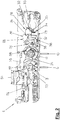
Figuren 1 und 2- ein Schloss im Funktionszustand "Tagfunktion",
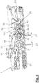
Figuren 3 und 4- das Schloss gemäß
den Figuren 1 und2 im Funktionszustand "Nachtfunktion" mit vorstehender Falle und zurückgezogenem Riegel, - Figuren 5 und 6
- das Schloss gemäß
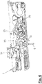
den Figuren 1 bis 4 im Funktionszustand "Nachtfunktion" mit vorstehender Falle und unmittelbar nach dem Ausschließen des Riegels und Figur 7- eine Teildarstellung des Schlosses gemäß
den Figuren 1 im Funktionszustand "Nachtfunktion" mit vorstehender Falle und ausgeschlossenem Riegel.bis 6
- Figures 1 and 2
- a lock in the functional state "day function",
- FIGS. 3 and 4
- the castle according to the
FIGS. 1 and2 in the functional state "night function" with the above case and retracted latch, - FIGS. 5 and 6
- the castle according to the
FIGS. 1 to 4 in the functional state "night function" with the above case and immediately after the exclusion of the bolt and - FIG. 7
- a partial view of the castle according to the
FIGS. 1 to 6 in the functional state "Night function" with the above case and locked bolt.
In den
In den
Die Schieberplatte 3 gemäß den
Der innere Riegelantrieb 4 weist ein in den
Entsprechend umfasst der äußere Riegelantrieb 5 einen als äußeres Riegel-Betätigungsorgan vorgesehenen und in den
Anstelle des Innendrückers 6 und des Außendrückers 10 sind auch andersartige Betätigungsorgane, beispielsweise ein Innenknauf und ein Außenknauf denkbar. Die Innendrückernuss 9 und die Außendrückernuss 10 sind gegeneinander versetzt.Instead of the
Aufgrund ihrer Zugehörigkeit sowohl zu dem inneren Riegelgetriebe 7 als auch zu dem äußeren Riegelgetriebe 11 bildet die Schieberplatte 3 ein gemeinsames Riegelgetriebeelement.Due to their affiliation both to the
In ein an der Schieberplatte 3 vorgesehenes Langloch 13, dessen Längsachse senkrecht zu dem nicht gezeigten Schlossstulp verläuft, greift ein Zapfen 14 ein. Dieser steht an einem ersten Schwenkhebel 15 vor, der ausweislich
Wie in
Entsprechendes gilt für die Innendrückernuss 9 und einen auf dieser aufsitzenden zweiten Schwenkhebel 20. Die Innendrückernuss 9 ist mit einem radialen Vorsprung 21 versehen, der im Innern einer radialen Erweiterung 22 eines Lagerauges 23 an dem zweiten Schwenkhebel 20 liegt. Aufgrund eines Übermaßes der radialen Erweiterung 22 gegenüber dem radialen Vorsprung 21 ergibt sich die Relativbeweglichkeit der Innendrückernuss 9 und des zweiten Schwenkhebels 20 um eine Drehachse 24. Bei der Drehachse 24 handelt es sich gleichzeitig um die Achse der Drehlagerung der Innendrückernuss 9 an dem Schlosskasten 2.The same applies to the
Über eine Verbindungsstange 25, die in den
Der äußere Riegelantrieb 5 kann in einen aktivierten oder einen deaktivierten Zustand überführt werden. Zu diesem Zweckt dient eine Schalteinrichtung 28, die in den
Die Schalteinrichtung 28 umfasst einen an dem Schlosskasten 2 senkrecht zu dem Schlossstulp geführten Querschieber 29, einen an dem Schlosskasten 2 drehbeweglich gelagerten zweiarmigen Schalthebel 30 sowie einen gleichfalls an dem Schlosskasten 2 drehbeweglich gelagerten zweiarmigen Blockierhebel 31.The switching
Der Querschieber 29 ist an einer Betätigungsseite 32 mit einem oberen Anschlag 33 und einem unteren Anschlag 34 versehen (
Der zweiarmige Schalthebel 30 der Schalteinrichtung 28 besitzt einen zu dem Querschieber 29 hin weisenden Betätigungsarm 40 sowie einen gegenüber dem Betätigungsarm 40 abgewinkelten und zu dem Blockierhebel 31 hin weisenden Schaltarm 41 (
An der zu dem Schlossstulp hin gelegenen Seite des Querschiebers 29 ist der Riegel 8 angeordnet. Mit einem unter anderem in
Der Führungsschlitz 47 an dem Riegelschwanz 46 des Riegels 8 nimmt einen Führungszapfen 50 auf, der an der von dem Betrachter der
Zusätzlich zu dem Riegel 8 weist das Schloss 1 eine Falle 51 auf. In gewohnter Weise wird die Falle 51 durch eine Fallenfeder 52 (
Als inneres Fallen-Betätigungsorgan des inneren Fallenantriebs 53 ist der außerdem als inneres Riegel-Betätigungsorgan dienende Innendrücker 6 vorgesehen, der mithin ein gemeinsames inneres Betätigungsorgan bildet. In entsprechender Weise wird der Außendrücker 10 als gemeinsames äußeres Betätigungsorgan und somit sowohl als das äußere Riegel-Betätigungsorgan des äußeren Riegelantriebes 5 als auch als äußeres Fallen-Betätigungsorgan des äußeren Fallenantriebs 54 genutzt.As an inner trap actuator of the inner latch drive 53 which also serves as an inner latch actuator
Dem inneren Fallenantrieb 53 und dem äußeren Fallenantrieb 54 gemeinsam sind ein längs des Schlossstulps verschiebbarer Fallenantriebsschieber 55 sowie ein zwischen dem Fallenantriebsschieber 55 und der Falle 51 vorgesehenes Umlenkgetriebe 56. Dem Fallenantriebsschieber 55 sind an der Innendrückernuss 9 eine Anschlagfläche 57 und an der Außendrückernuss 12 ein Anschlagbolzen 58 zugeordnet.Common to the inner latch drive 53 and the
Die
Die Falle 51 befindet sich in den
In einer Ansicht gemäß
Zum Verriegeln des Schlosses 1 ist ausgehend von den Verhältnissen gemäß den
Wird zum Verriegeln des Schlosses 1 ausgehend von den Verhältnissen gemäß den
Unabhängig davon, ob der Riegel 8 durch Betätigen des Außendrückers 10 oder durch Betätigen des Innendrückers 6 aus dem Entriegelungszustand in den Verriegelungszustand überführt worden ist, ergeben sich an der Rückseite der Innendrückernuss 9 und der Außendrückernuss 12 abgesehen von dem Schaltzustand der Schalteinrichtung 28 die in
Wird ausgehend von diesen Verhältnissen der bei Einbaulage des Schlosses 1 horizontal ausgerichtete Außendrücker 10 in Richtung eines Pfeils 62 niedergedrückt, so treibt der Außendrücker 10 über die Außendrückernuss 12 den Schwenkhebel 15 in
Bei fortgesetztem Niederdrücken des Außendrückers 10 in Richtung des Pfeils 62 läuft der Anschlagbolzen 58 an der Außendrückernuss 12 auf den Fallenantriebsschieber 55 auf und verschiebt diesen in
Aufgrund der über die Verbindungsstange 25 herstellten Anbindung an den Schwenkhebel 15 können auch durch vollständiges Niederdrücken des Innendrückers 6 ausgehend von den Verhältnissen gemäß
Um ein Öffnen der mit dem Schloss 1 versehenen Tür mittels des Außendrückers 10 von der Raumaußenseite her zu verhindern, muss das Schloss 1 in den Funktionszustand "Nachtmodus" bzw. "Nachtfunktion" geschaltet werden.In order to prevent opening of the door provided with the
Dies geschieht, indem der Querschieber 29 der Schalteinrichtung 28 durch Schlüsselbetätigung aus seiner Aktivierungsstellung gemäß den
Bei seiner Bewegung in Richtung auf den Schlossstulp schwenkt der Querschieber 29 den Schalthebel 30 der Schalteinrichtung 28 ausgehend von dessen Schwenkstellung gemäß
Damit sind der äußere Riegelantrieb 5 und der äußere Fallenantrieb 54 deaktiviert. Der Außendrücker 10 ist über den Blockieranschlag 45 an der Außendrückernuss 12 und das freie Ende des Blockierarms 44 an dem Blockierhebel 31 der Schalteinrichtung 28 gegen Niederdrücken in Pfeilrichtung 62 blockiert.Thus, the outer latch drive 5 and the
Die Deaktivierung des äußeren Fallenantriebes 54 macht sich bei dem Funktionszustand des Schlosses 1 gemäß den
Möglich ist eine derartige Überführung der Falle 51 aus dem vorstehenden Zustand in den zurückgezogenen Zustand mittels des Innendrückers 6 bzw. mittels des inneren Fallenantriebes 53.Such a transfer of the
Zwar ist der auf der Innendrückernuss 9 aufsitzende zweite Schwenkhebel 20 zur Verriegelung des Schlosses 1 über die Verbindungsstange 25 an die Außendrückernuss 12 des deaktivierten äußeren Riegelantriebes 5 und des gleichfalls deaktivierten äußeren Fallenantriebes 54 angebunden; dennoch wirkt sich die Deaktivierung, d.h. die Blockierung des äußeren Riegelantriebes 5 und des äußeren Fallenantriebes 54, nicht auf die für ein Zurückziehen der Falle 51 mittels des Innendrückers 6 erforderliche Drehbeweglichkeit der Innendrückernuss 9 aus.Although the seated on the
Grund hierfür ist die Drehstellung, welche bei den Verhältnissen gemäß den
Daher kann sich die Innendrückernuss 9 in
Befindet sich das Schloss 1 in dem Funktionszustand "nichtfunktion" und ist der Riegel 8 gemäß den
Die Abläufe beim Verriegeln des Schlosses 1 mittels des Innendrückers 6 und des Außendrückers 10 entsprechen den vorstehend zu den
Der Außendrücker 10 ist demnach aus der Stellung gemäß
An dem in die Nachtfunktion geschalteten Schloss 1 wird demnach durch die Schalteinrichtung 28 eine Überführung des Riegels 8 aus dem Entriegelungszustand in den Verriegelungszustand zugelassen. Durch die Schalteinrichtung 28 blockiert wird aber eine mittels des Außendrückers 10 realisierte Überführung des Riegels 8 aus dem Verriegelungszustand in den Entriegelungszustand. Ein zu diesem Zweck erforderliches Niederdrücken des Außendrückers 10 wird durch die Schalteinrichtung 28, im Einzelnen durch den an den Blockieranschlag 45 der Außendrückernuss 12 anschlagenden Blockierhebel 31 der Schalteinrichtung 28 verhindert.At the switched into the
Gleichwohl kann der in den Verriegelungszustand überführte Riegel 8 mittels des inneren Riegelantriebes 4 in den Entriegelungszustand überführt werden. Diese Möglichkeit besteht aufgrund der Tatsache, dass der äußere Riegelantrieb 5 ausschließlich entkoppelt von der auch von dem inneren Riegelantrieb 4 genutzten Schieberplatte 3 deaktiviert ist. Die Schieberplatte 3 kann durch Niederdrücken des Innendrückers 6 trotz der an der Außendrückernuss 12 realisierten Blockade des äußeren Riegelantriebes 5 mit einer Entriegelungsbewegung stulpparallel verschoben werden.Nevertheless, the bar 8 transferred to the locking state can be transferred into the unlocking state by means of the inner latch drive 4. This possibility exists due to the fact that the outer latch drive 5 is deactivated only decoupled from the
Das Niederdrücken des Innendrückers 6 bewirkt über die Innendrückernuss 9, die Verbindungsstange 25 und den ersten Schwenkhebel 15 eine Verlagerung der Schieberplatte 3 ausgehend von ihrer Position gemäß
Infolge der mittels des Innendrückers 6 bewirkten stulpparallelen Entriegelungsbewegung der Schieberplatte 3 wird der Riegel 8 über den Führungszapfen 50 an der Schieberplatte 3 und den Führungsschlitz 47 an dem Riegelschwanz 46 in das Innere des Schlosskastens 2 zurückgezogen. Bei vollständigem Niederdrücken des Innendrückers 6 wird der Fallenantriebsschieber 55 durch die Innendrückernuss 9 in der vorstehend zu den
Somit kann die mit dem Schloss 1 versehene Tür von der Rauminnenseite her auch dann allein mittels des Innendrückers 6 geöffnet werden, wenn ein Öffnen der Tür von der Türaußenseite her mittels des Außendrückers 12 nicht möglich ist.Thus, the door provided with the
Sollen der äußere Riegelantrieb 5 und der äußere Fallenantrieb 54 wieder aktiviert werden, so ist der Querschieber 29 durch Schlüsselbetätigung aus der Deaktivierungsstellung gemäß den
Nun können auch wieder durch Niederdrücken des Außendrückers 10 die Falle 51 aus dem vorstehenden Zustand in den zurückgezogenen Zustand und der Riegel 8 aus dem Verriegelungszustand in den Entriegelungszustand überführt werden.Now, again by depressing the
Claims (10)
- Lock for a door, a window or the like,• having a bolt (8)• having an inner bolt drive (4) which has an inner bolt actuation member (6) which is associated with an inner room side and an inner bolt gear mechanism (7) between the inner bolt actuation member (6) and the bolt (8) and by means of which the bolt (8) can be moved from a locking state into an unlocking state,• having an outer bolt drive (5) which can be activated and deactivated and which has an outer bolt actuation member (10) which is associated with an outer room side and an outer bolt gear mechanism (11) between the outer bolt actuation member (10) and the bolt (8) and for which there is provided an actuatable switching device (28), by means of the actuation of which the activated outer bolt drive (5) can be deactivated, wherein the bolt (8) can be moved by means of the activated outer bolt drive (5) from a locking state into an unlocking state and wherein the deactivated outer bolt drive (5) is blocked by means of the switching device (28) against a transfer of the bolt (8) from a locking state into an unlocking state, and• having at least one bolt gear element (3) which is common to the inner bolt gear mechanism (7) and the outer bolt gear mechanism (11) and which can be driven by means of the inner bolt actuation member (6) or by means of the outer bolt actuation member (10) with an unlocking movement in order to transfer the bolt (8) from a locking state into an unlocking state,• wherein the bolt (8) with the outer bolt drive (5) deactivated can be transferred by means of the inner bolt actuation member (6) from a locking state into an unlocking state by the outer bolt drive (5) between the common bolt gear element (3) and the outer bolt actuation member (10) being deactivated in a state decoupled from the common bolt gear element (3), and by the common bolt gear element (3) with the outer bolt drive (5) being deactivated being able to be driven by means of the inner bolt actuation member (6) with an unlocking movement,characterised in that
the switching device (28) for the outer bolt drive (5) can be actuated by means of key actuation in a sense which deactivates the outer bolt drive (5). - Lock according to claim 1, characterised in that• a latch (51) and an inner latch drive (53) are provided, wherein the latch (51) can be transferred by means of the inner latch drive (53) from a protruding state into a retracted state,• in that the inner latch drive (53) has as an inner latch actuation member which is associated with the inner room side the inner bolt actuation member (6) which forms an inner actuation member which is common to the inner latch drive (53) and the inner bolt drive (4) and• in that, when the outer bolt drive (5) is deactivated, by means of the common inner actuation member in addition to the transfer of the bolt (8) from a locking state into an unlocking state, the latch (51) can be transferred from a protruding state into a retracted state by the inner latch drive (53) being decoupled from the deactivation of the outer bolt drive (5), which deactivation is provided between the common bolt gear element (3) and the outer bolt actuation member (6).
- Lock according to either of the preceding claims, characterised in that the switching device (28) for the outer bolt drive (5) can be actuated both from the inner room side and from the outer room side.
- Lock according to any one of the preceding claims, characterised in that the switching device (28) for the outer bolt drive (5) has a switching element (29) which can be moved into an activation position which is associated with the activated state of the outer bolt drive (5) and, by actuating the switching device (28), into a deactivation position which is associated with the deactivated state of the outer bolt drive (5) .
- Lock according to any one of the preceding claims, characterised in that the switching element (29) of the switching device (28) for the outer bolt drive (5) is releasably secured in the activation position by means of a securing device (38) and in that the securing of the switching element (29) can be released by actuating the switching device (28).
- Lock according to any one of the preceding claims, characterised in that the switching element (29) of the switching device (28) for the outer bolt drive (5) is releasably engaged in the activation position by means of the securing device (38) .
- Lock according to any one of the preceding claims, characterised in that the switching element (29) of the switching device (28) for the outer bolt drive (5) is secured in the activation position by means of the securing device (38) counter to the action of a restoring force which acts on the switching element (29) in the direction towards the deactivation position.
- Lock according to any one of the preceding claims, characterised in that the bolt (8) with the outer bolt drive (5) activated and deactivated can be transferred from an unlocking state into a locking state.
- Lock according to any one of the preceding claims, characterised in that the bolt (8) can be transferred from an unlocking state into a locking state by means of the activated and by means of the deactivated outer bolt drive (5).
- Lock according to any one of the preceding claims, characterised in that• there is provided an outer latch drive (54) which can be activated and deactivated and which has, as an outer latch actuation member associated with the outer room side, the outer bolt actuation member (10), which forms an outer actuation member which is common to the outer latch drive (54) and the outer bolt drive (5),• in that there is provided for the outer latch drive (54) as an actuatable switching device, by means of the actuation of which the activated outer latch drive (54) can be deactivated, the actuatable switching device (28) for the outer bolt drive (5), which switching device forms a switching device which is common to the outer latch drive (54) and the outer bolt drive (5),• in that the latch (51) can be transferred by means of the activated outer latch drive (54) from a protruding state into a retracted state and the deactivated outer latch drive (54) is blocked by means of the common switching device counter to a transfer of the latch (51) from a protruding state into a retracted state, and• in that the latch (51) with the outer latch drive (54) deactivated can be transferred by means of the inner latch drive (53) from a protruding state into a retracted state by the inner latch drive (53) being decoupled from the deactivation of the outer latch drive (54).
Priority Applications (1)
| Application Number | Priority Date | Filing Date | Title |
|---|---|---|---|
| EP12157899.1A EP2634332B1 (en) | 2012-03-02 | 2012-03-02 | Lock for a window, door or similar |
Applications Claiming Priority (1)
| Application Number | Priority Date | Filing Date | Title |
|---|---|---|---|
| EP12157899.1A EP2634332B1 (en) | 2012-03-02 | 2012-03-02 | Lock for a window, door or similar |
Publications (2)
| Publication Number | Publication Date |
|---|---|
| EP2634332A1 EP2634332A1 (en) | 2013-09-04 |
| EP2634332B1 true EP2634332B1 (en) | 2017-05-03 |
Family
ID=45841231
Family Applications (1)
| Application Number | Title | Priority Date | Filing Date |
|---|---|---|---|
| EP12157899.1A Not-in-force EP2634332B1 (en) | 2012-03-02 | 2012-03-02 | Lock for a window, door or similar |
Country Status (1)
| Country | Link |
|---|---|
| EP (1) | EP2634332B1 (en) |
Family Cites Families (2)
| Publication number | Priority date | Publication date | Assignee | Title |
|---|---|---|---|---|
| EP1672153B1 (en) | 2004-12-18 | 2013-12-11 | Roto Frank Ag | Lock with dead bolt and dead bolt actuating device |
| EP1953313B1 (en) * | 2007-02-02 | 2014-01-29 | Roto Frank Ag | Lock for door |
-
2012
- 2012-03-02 EP EP12157899.1A patent/EP2634332B1/en not_active Not-in-force
Also Published As
| Publication number | Publication date |
|---|---|
| EP2634332A1 (en) | 2013-09-04 |
Similar Documents
| Publication | Publication Date | Title |
|---|---|---|
| EP1932989B1 (en) | Locking device for doors, windows or similar, in particular an espagnolette lock with panic function and multi-point locking | |
| EP1574644A2 (en) | Locking system for doors, windows or similar, in particular espagnolette lock with anti-panic function and multiple lock points | |
| EP0861960B1 (en) | Security lock | |
| EP2179116A1 (en) | Door lock | |
| EP2248966B1 (en) | Door lock with locking element and switchable locking element drive | |
| EP2692969A1 (en) | Gear of a drive rod fixture, drive rod fixture with such a gear and window, door or similar with such a drive rod fixture | |
| EP2715019B1 (en) | Motor vehicle door lock | |
| DE4323493C1 (en) | Number-combination lock with a rotary knob, with a cam disc and with a drop-in lever | |
| EP1953313B1 (en) | Lock for door | |
| DE202005000939U1 (en) | Locking arrangement for door or window with drive rods 30 connecting auxiliary locks to main lock has pressure knob on main lock with pivoting lever moving bolt and drive rods | |
| EP1683936B1 (en) | Lock with latch and latch drive | |
| EP3045624A1 (en) | Locking device for a pivoting mounted wing | |
| EP2072725A2 (en) | Espagnolette locking device | |
| DE19630972A1 (en) | Lock | |
| DE202009016137U1 (en) | Espagnolette lock with panic function and multiple locking | |
| EP2634332B1 (en) | Lock for a window, door or similar | |
| EP1672153B1 (en) | Lock with dead bolt and dead bolt actuating device | |
| EP1617018B1 (en) | Electromechanical door lock | |
| EP3122970B1 (en) | Switch lock for locking bar with spring | |
| EP2738324B1 (en) | Lock with a releasable rotating unit | |
| EP3662123B1 (en) | Motor lock | |
| EP2453086B1 (en) | Connecting rod for the fixed leaf of double-leafed windows or doors without mullion | |
| DE2605763C3 (en) | Espagnolette lock with latch | |
| AT406496B (en) | MULTI-LOCK LOCK | |
| EP2615229A2 (en) | Locking facility |
Legal Events
| Date | Code | Title | Description |
|---|---|---|---|
| PUAI | Public reference made under article 153(3) epc to a published international application that has entered the european phase |
Free format text: ORIGINAL CODE: 0009012 |
|
| AK | Designated contracting states |
Kind code of ref document: A1 Designated state(s): AL AT BE BG CH CY CZ DE DK EE ES FI FR GB GR HR HU IE IS IT LI LT LU LV MC MK MT NL NO PL PT RO RS SE SI SK SM TR |
|
| AX | Request for extension of the european patent |
Extension state: BA ME |
|
| 17P | Request for examination filed |
Effective date: 20140226 |
|
| RBV | Designated contracting states (corrected) |
Designated state(s): AL AT BE BG CH CY CZ DE DK EE ES FI FR GB GR HR HU IE IS IT LI LT LU LV MC MK MT NL NO PL PT RO RS SE SI SK SM TR |
|
| 17Q | First examination report despatched |
Effective date: 20140423 |
|
| GRAJ | Information related to disapproval of communication of intention to grant by the applicant or resumption of examination proceedings by the epo deleted |
Free format text: ORIGINAL CODE: EPIDOSDIGR1 |
|
| GRAP | Despatch of communication of intention to grant a patent |
Free format text: ORIGINAL CODE: EPIDOSNIGR1 |
|
| RIC1 | Information provided on ipc code assigned before grant |
Ipc: E05B 65/10 20060101AFI20161019BHEP Ipc: E05B 59/00 20060101ALI20161019BHEP Ipc: E05B 63/16 20060101ALN20161019BHEP |
|
| INTG | Intention to grant announced |
Effective date: 20161116 |
|
| RIC1 | Information provided on ipc code assigned before grant |
Ipc: E05B 65/10 20060101AFI20161108BHEP Ipc: E05B 63/16 20060101ALN20161108BHEP Ipc: E05B 59/00 20060101ALI20161108BHEP |
|
| GRAS | Grant fee paid |
Free format text: ORIGINAL CODE: EPIDOSNIGR3 |
|
| GRAA | (expected) grant |
Free format text: ORIGINAL CODE: 0009210 |
|
| AK | Designated contracting states |
Kind code of ref document: B1 Designated state(s): AL AT BE BG CH CY CZ DE DK EE ES FI FR GB GR HR HU IE IS IT LI LT LU LV MC MK MT NL NO PL PT RO RS SE SI SK SM TR |
|
| REG | Reference to a national code |
Ref country code: GB Ref legal event code: FG4D Free format text: NOT ENGLISH |
|
| REG | Reference to a national code |
Ref country code: AT Ref legal event code: REF Ref document number: 890178 Country of ref document: AT Kind code of ref document: T Effective date: 20170515 Ref country code: CH Ref legal event code: EP |
|
| REG | Reference to a national code |
Ref country code: IE Ref legal event code: FG4D Free format text: LANGUAGE OF EP DOCUMENT: GERMAN |
|
| REG | Reference to a national code |
Ref country code: DE Ref legal event code: R096 Ref document number: 502012010216 Country of ref document: DE |
|
| REG | Reference to a national code |
Ref country code: NL Ref legal event code: MP Effective date: 20170503 |
|
| REG | Reference to a national code |
Ref country code: LT Ref legal event code: MG4D |
|
| PG25 | Lapsed in a contracting state [announced via postgrant information from national office to epo] |
Ref country code: ES Free format text: LAPSE BECAUSE OF FAILURE TO SUBMIT A TRANSLATION OF THE DESCRIPTION OR TO PAY THE FEE WITHIN THE PRESCRIBED TIME-LIMIT Effective date: 20170503 Ref country code: LT Free format text: LAPSE BECAUSE OF FAILURE TO SUBMIT A TRANSLATION OF THE DESCRIPTION OR TO PAY THE FEE WITHIN THE PRESCRIBED TIME-LIMIT Effective date: 20170503 Ref country code: HR Free format text: LAPSE BECAUSE OF FAILURE TO SUBMIT A TRANSLATION OF THE DESCRIPTION OR TO PAY THE FEE WITHIN THE PRESCRIBED TIME-LIMIT Effective date: 20170503 Ref country code: NO Free format text: LAPSE BECAUSE OF FAILURE TO SUBMIT A TRANSLATION OF THE DESCRIPTION OR TO PAY THE FEE WITHIN THE PRESCRIBED TIME-LIMIT Effective date: 20170803 Ref country code: FI Free format text: LAPSE BECAUSE OF FAILURE TO SUBMIT A TRANSLATION OF THE DESCRIPTION OR TO PAY THE FEE WITHIN THE PRESCRIBED TIME-LIMIT Effective date: 20170503 Ref country code: GR Free format text: LAPSE BECAUSE OF FAILURE TO SUBMIT A TRANSLATION OF THE DESCRIPTION OR TO PAY THE FEE WITHIN THE PRESCRIBED TIME-LIMIT Effective date: 20170804 |
|
| PG25 | Lapsed in a contracting state [announced via postgrant information from national office to epo] |
Ref country code: LV Free format text: LAPSE BECAUSE OF FAILURE TO SUBMIT A TRANSLATION OF THE DESCRIPTION OR TO PAY THE FEE WITHIN THE PRESCRIBED TIME-LIMIT Effective date: 20170503 Ref country code: BG Free format text: LAPSE BECAUSE OF FAILURE TO SUBMIT A TRANSLATION OF THE DESCRIPTION OR TO PAY THE FEE WITHIN THE PRESCRIBED TIME-LIMIT Effective date: 20170803 Ref country code: PL Free format text: LAPSE BECAUSE OF FAILURE TO SUBMIT A TRANSLATION OF THE DESCRIPTION OR TO PAY THE FEE WITHIN THE PRESCRIBED TIME-LIMIT Effective date: 20170503 Ref country code: NL Free format text: LAPSE BECAUSE OF FAILURE TO SUBMIT A TRANSLATION OF THE DESCRIPTION OR TO PAY THE FEE WITHIN THE PRESCRIBED TIME-LIMIT Effective date: 20170503 Ref country code: IS Free format text: LAPSE BECAUSE OF FAILURE TO SUBMIT A TRANSLATION OF THE DESCRIPTION OR TO PAY THE FEE WITHIN THE PRESCRIBED TIME-LIMIT Effective date: 20170903 Ref country code: RS Free format text: LAPSE BECAUSE OF FAILURE TO SUBMIT A TRANSLATION OF THE DESCRIPTION OR TO PAY THE FEE WITHIN THE PRESCRIBED TIME-LIMIT Effective date: 20170503 Ref country code: SE Free format text: LAPSE BECAUSE OF FAILURE TO SUBMIT A TRANSLATION OF THE DESCRIPTION OR TO PAY THE FEE WITHIN THE PRESCRIBED TIME-LIMIT Effective date: 20170503 |
|
| PG25 | Lapsed in a contracting state [announced via postgrant information from national office to epo] |
Ref country code: CZ Free format text: LAPSE BECAUSE OF FAILURE TO SUBMIT A TRANSLATION OF THE DESCRIPTION OR TO PAY THE FEE WITHIN THE PRESCRIBED TIME-LIMIT Effective date: 20170503 Ref country code: DK Free format text: LAPSE BECAUSE OF FAILURE TO SUBMIT A TRANSLATION OF THE DESCRIPTION OR TO PAY THE FEE WITHIN THE PRESCRIBED TIME-LIMIT Effective date: 20170503 Ref country code: EE Free format text: LAPSE BECAUSE OF FAILURE TO SUBMIT A TRANSLATION OF THE DESCRIPTION OR TO PAY THE FEE WITHIN THE PRESCRIBED TIME-LIMIT Effective date: 20170503 Ref country code: RO Free format text: LAPSE BECAUSE OF FAILURE TO SUBMIT A TRANSLATION OF THE DESCRIPTION OR TO PAY THE FEE WITHIN THE PRESCRIBED TIME-LIMIT Effective date: 20170503 Ref country code: SK Free format text: LAPSE BECAUSE OF FAILURE TO SUBMIT A TRANSLATION OF THE DESCRIPTION OR TO PAY THE FEE WITHIN THE PRESCRIBED TIME-LIMIT Effective date: 20170503 |
|
| REG | Reference to a national code |
Ref country code: DE Ref legal event code: R097 Ref document number: 502012010216 Country of ref document: DE |
|
| PG25 | Lapsed in a contracting state [announced via postgrant information from national office to epo] |
Ref country code: SM Free format text: LAPSE BECAUSE OF FAILURE TO SUBMIT A TRANSLATION OF THE DESCRIPTION OR TO PAY THE FEE WITHIN THE PRESCRIBED TIME-LIMIT Effective date: 20170503 Ref country code: IT Free format text: LAPSE BECAUSE OF FAILURE TO SUBMIT A TRANSLATION OF THE DESCRIPTION OR TO PAY THE FEE WITHIN THE PRESCRIBED TIME-LIMIT Effective date: 20170503 |
|
| PLBE | No opposition filed within time limit |
Free format text: ORIGINAL CODE: 0009261 |
|
| STAA | Information on the status of an ep patent application or granted ep patent |
Free format text: STATUS: NO OPPOSITION FILED WITHIN TIME LIMIT |
|
| 26N | No opposition filed |
Effective date: 20180206 |
|
| PG25 | Lapsed in a contracting state [announced via postgrant information from national office to epo] |
Ref country code: SI Free format text: LAPSE BECAUSE OF FAILURE TO SUBMIT A TRANSLATION OF THE DESCRIPTION OR TO PAY THE FEE WITHIN THE PRESCRIBED TIME-LIMIT Effective date: 20170503 |
|
| PG25 | Lapsed in a contracting state [announced via postgrant information from national office to epo] |
Ref country code: MT Free format text: LAPSE BECAUSE OF FAILURE TO SUBMIT A TRANSLATION OF THE DESCRIPTION OR TO PAY THE FEE WITHIN THE PRESCRIBED TIME-LIMIT Effective date: 20170503 |
|
| REG | Reference to a national code |
Ref country code: CH Ref legal event code: PL |
|
| GBPC | Gb: european patent ceased through non-payment of renewal fee |
Effective date: 20180302 |
|
| PG25 | Lapsed in a contracting state [announced via postgrant information from national office to epo] |
Ref country code: MC Free format text: LAPSE BECAUSE OF FAILURE TO SUBMIT A TRANSLATION OF THE DESCRIPTION OR TO PAY THE FEE WITHIN THE PRESCRIBED TIME-LIMIT Effective date: 20170503 |
|
| REG | Reference to a national code |
Ref country code: BE Ref legal event code: MM Effective date: 20180331 |
|
| REG | Reference to a national code |
Ref country code: IE Ref legal event code: MM4A |
|
| PG25 | Lapsed in a contracting state [announced via postgrant information from national office to epo] |
Ref country code: LU Free format text: LAPSE BECAUSE OF NON-PAYMENT OF DUE FEES Effective date: 20180302 |
|
| PG25 | Lapsed in a contracting state [announced via postgrant information from national office to epo] |
Ref country code: IE Free format text: LAPSE BECAUSE OF NON-PAYMENT OF DUE FEES Effective date: 20180302 |
|
| PG25 | Lapsed in a contracting state [announced via postgrant information from national office to epo] |
Ref country code: LI Free format text: LAPSE BECAUSE OF NON-PAYMENT OF DUE FEES Effective date: 20180331 Ref country code: CH Free format text: LAPSE BECAUSE OF NON-PAYMENT OF DUE FEES Effective date: 20180331 Ref country code: BE Free format text: LAPSE BECAUSE OF NON-PAYMENT OF DUE FEES Effective date: 20180331 Ref country code: GB Free format text: LAPSE BECAUSE OF NON-PAYMENT OF DUE FEES Effective date: 20180302 |
|
| PG25 | Lapsed in a contracting state [announced via postgrant information from national office to epo] |
Ref country code: FR Free format text: LAPSE BECAUSE OF NON-PAYMENT OF DUE FEES Effective date: 20180331 |
|
| PGFP | Annual fee paid to national office [announced via postgrant information from national office to epo] |
Ref country code: DE Payment date: 20190321 Year of fee payment: 8 |
|
| REG | Reference to a national code |
Ref country code: AT Ref legal event code: MM01 Ref document number: 890178 Country of ref document: AT Kind code of ref document: T Effective date: 20180302 |
|
| PG25 | Lapsed in a contracting state [announced via postgrant information from national office to epo] |
Ref country code: AT Free format text: LAPSE BECAUSE OF NON-PAYMENT OF DUE FEES Effective date: 20180302 |
|
| PG25 | Lapsed in a contracting state [announced via postgrant information from national office to epo] |
Ref country code: TR Free format text: LAPSE BECAUSE OF FAILURE TO SUBMIT A TRANSLATION OF THE DESCRIPTION OR TO PAY THE FEE WITHIN THE PRESCRIBED TIME-LIMIT Effective date: 20170503 |
|
| PG25 | Lapsed in a contracting state [announced via postgrant information from national office to epo] |
Ref country code: PT Free format text: LAPSE BECAUSE OF FAILURE TO SUBMIT A TRANSLATION OF THE DESCRIPTION OR TO PAY THE FEE WITHIN THE PRESCRIBED TIME-LIMIT Effective date: 20170503 Ref country code: HU Free format text: LAPSE BECAUSE OF FAILURE TO SUBMIT A TRANSLATION OF THE DESCRIPTION OR TO PAY THE FEE WITHIN THE PRESCRIBED TIME-LIMIT; INVALID AB INITIO Effective date: 20120302 |
|
| PG25 | Lapsed in a contracting state [announced via postgrant information from national office to epo] |
Ref country code: MK Free format text: LAPSE BECAUSE OF NON-PAYMENT OF DUE FEES Effective date: 20170503 Ref country code: CY Free format text: LAPSE BECAUSE OF FAILURE TO SUBMIT A TRANSLATION OF THE DESCRIPTION OR TO PAY THE FEE WITHIN THE PRESCRIBED TIME-LIMIT Effective date: 20170503 |
|
| PG25 | Lapsed in a contracting state [announced via postgrant information from national office to epo] |
Ref country code: AL Free format text: LAPSE BECAUSE OF FAILURE TO SUBMIT A TRANSLATION OF THE DESCRIPTION OR TO PAY THE FEE WITHIN THE PRESCRIBED TIME-LIMIT Effective date: 20170503 |
|
| REG | Reference to a national code |
Ref country code: DE Ref legal event code: R119 Ref document number: 502012010216 Country of ref document: DE |
|
| PG25 | Lapsed in a contracting state [announced via postgrant information from national office to epo] |
Ref country code: DE Free format text: LAPSE BECAUSE OF NON-PAYMENT OF DUE FEES Effective date: 20201001 |