EP2634332B1 - Serrure pour une porte, une fenêtre ou analogue - Google Patents
Serrure pour une porte, une fenêtre ou analogue Download PDFInfo
- Publication number
- EP2634332B1 EP2634332B1 EP12157899.1A EP12157899A EP2634332B1 EP 2634332 B1 EP2634332 B1 EP 2634332B1 EP 12157899 A EP12157899 A EP 12157899A EP 2634332 B1 EP2634332 B1 EP 2634332B1
- Authority
- EP
- European Patent Office
- Prior art keywords
- bolt
- drive
- latch
- state
- lock
- Prior art date
- Legal status (The legal status is an assumption and is not a legal conclusion. Google has not performed a legal analysis and makes no representation as to the accuracy of the status listed.)
- Not-in-force
Links
Images


Classifications
-
- E—FIXED CONSTRUCTIONS
- E05—LOCKS; KEYS; WINDOW OR DOOR FITTINGS; SAFES
- E05B—LOCKS; ACCESSORIES THEREFOR; HANDCUFFS
- E05B65/00—Locks or fastenings for special use
- E05B65/10—Locks or fastenings for special use for panic or emergency doors
- E05B65/1086—Locks with panic function, e.g. allowing opening from the inside without a ley even when locked from the outside
-
- E—FIXED CONSTRUCTIONS
- E05—LOCKS; KEYS; WINDOW OR DOOR FITTINGS; SAFES
- E05B—LOCKS; ACCESSORIES THEREFOR; HANDCUFFS
- E05B59/00—Locks with latches separate from the lock-bolts or with a plurality of latches or lock-bolts
-
- E—FIXED CONSTRUCTIONS
- E05—LOCKS; KEYS; WINDOW OR DOOR FITTINGS; SAFES
- E05B—LOCKS; ACCESSORIES THEREFOR; HANDCUFFS
- E05B63/00—Locks or fastenings with special structural characteristics
- E05B63/16—Locks or fastenings with special structural characteristics with the handles on opposite sides moving independently
Definitions
- a drive lever Via a drive lever, which is mounted on both the internal pressure nut and on the external pressure nut with a radial distance from the axis of rotation, the internal pressure nut and the outer pressure nut are connected to one another.
- the external pusher nut engages a slide plate, which can be moved inside the lock case parallel to a lock plate.
- the slide plate leads in a guide slot provided on the bolt guide pin.
- the slide plate is provided with an open-edge recess for a locking tab provided on a locking lug.
- the bolt can by both depressing the inner handle as also be withdrawn by depressing the outer handle in the interior of the lock box.
- a depression of the inner handle causes a rotational movement of the réelleend Wegernuss and the drive lever between the inner and the Aussend Wegernuss a same direction rotational movement of the Aussend Wegernuss.
- the rotational movement of the outer follower nut is in turn implemented in a retraction movement of the bolt in an unlocking movement of the slide plate directed along the lock tulip and the unlocking movement of the slide plate.
- Both the bolt drive means of the inner handle and the latch drive means of the outer handle are disabled due to the positive connection between the locking lug of the locking slide and the open-edge recess of the slide plate.
- this positive connection must first be released.
- the locking slide is moved away by key operation of the slide plate in a position in which the locking lug of the locking slide is outside the open-edge recess of the slide plate.
- a generic lock is disclosed in EP 1 953 313 A1 , This document describes a lock with a bolt which is movably guided on a lock case in an exclusion direction and in a retraction direction.
- a control groove on a bolt tail of the bolt engages a control pin, which in turn is mounted on a parallel to a lock plate displaceable drive and blocking slide.
- Actuator and control lever At the drive and blocking slide engages Actuator and control lever, which rests on a participatedd Wegernuss and can be pivoted by pressing an external handle. Pivoting movements of the drive and control lever generated by means of the outer pusher are converted into movements of the drive and blocking slide along the lock cuff.
- the bolt is moved in the direction of exclusion or in the retraction direction by means of the control pin provided on the drive and blocking slide and the latch-side control groove.
- the outer handle, the Aussendückernuss, the drive and control lever, the drive and locking slide and the control pin and the control groove form an outer latch drive.
- This outer latch drive can be switched to an activated or a deactivated state. When the outer latch drive is disabled, it is not possible to withdraw the excluded from the lock case latch means of the outer handle in the lock case and thereby convert the latch from a locked state to an unlocked state.
- the outer latch drive is activated and the latch is transferred to the locked state, the outer latch is to be depressed in an opening direction to deactivate the outer latch drive.
- the drive and lock slider drivingly connected to the outside handle drives the lock with movement in the return direction.
- the outer follower seated on the outer handle rotates due to the depression of the outer handle and acts on a shift lever with a control projection.
- the shift lever is part of a switching device for a locking device. Due to the application of the control projection on the outer pusher, the shift lever shifts a locking slide into a position in which the locking slide releases a cross slide guided on the lock case for movement in the direction of the lock cuff.
- a locking lever of the locking device is pivoted into a blocking position, in which the locking lever the Aussend Wegernuss and on this the outer handle against renewed movement blocked in the opening direction and thus deactivated the outer latch drive.
- the object of the present invention is to enable the deactivation of the outer latch drive with simplified structural means.
- the lock can according to claim 1 from the Be unlocked inside the room when the bolt drive is deactivated from the outside of the room. Accordingly, a so-called panic function on the inside of the castle is combined with a night mode on the outside of the castle.
- a key operation is expediently provided in the case of the invention.
- Erfindungsbauart in the case of Erfindungsbauart according to claim 2 can be with disabled outer latch drive from the room inside not only the latch from the locked state in the unlocking state but also transfer a case of the lock from a protruding state to a retracted state.
- the switching device for the outer latch drive both from the room inside and out of the room outside are operated.
- the lock type according to claim 4 a switching device for the outer latch drive with a switching element, which can be moved into an activation position and by operating the switching device in a deactivation position.
- the switching element is releasably locked in the activation position, preferably releasably latched (claims 5, 6). Due to the locking of the switching element in the activation position, the risk of malfunction of the lock is minimized. A deactivation of the outer latch drive and thus a blocking of the lock against unlocking from the outside of the room requires a prior release of the locking of the switching element and thus a deliberately executed action.
- the embodiment of the lock according to the invention described in claim 7 is characterized in that the switching element of the switching device for the outer latch drive is biased in locking in the activation position in the direction of the deactivation position.
- Claim 10 relates to a lock type according to the invention, which also has a trap in addition to a bolt.
- the outer latch actuator also serves as an outer latch actuator. Deactivation of the outer latch drive is consequently associated with deactivation of the outer latch drive.
- neither the latch can be transferred from the locked state into the unlocked state nor the latch can be transferred from the protruding state into the withdrawn state from the outside of the room. Nevertheless, it is at the same time from the inside of the room both a release of the lock and a retraction of the trap possible.
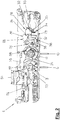
- a lock 1 is shown with a lock case 2 with removed lock box lid.
- the lock 1 is intended for mounting in a fold-side cutout of a door leaf, not shown.
- a lock plate of conventional design which rests in the installation position of the lock 1 on the rebate surface of the relevant door, is also not shown for the sake of simplicity.
- FIGS. 1 . 3 and 5 is inside the lock case 2 a slide plate 3 can be seen.
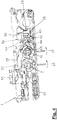
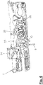
- the slide plate 3 is in the Figures 2 . 4 and 6 away. As a result, the view is free on the arranged under the slide plate 3 components of the castle. 1
- FIG. 7 shows selected components of the lock 1 in the view from the side of the lock 1, which the viewer of the FIGS. 1 to 6 turned away.
- the slide plate 3 according to the FIGS. 1 to 6 is part of both an inner latch drive 4 and an outer latch drive. 5
- the inner latch drive 4 has a in the FIGS. 1 to 6 indicated inner latch actuator in the form of an inner handle 6 and an inner latch transmission 7, which is disposed between the inner handle 6 and a latch 8 and includes, among other things, the slide plate 3.
- Another essential element of the inner locking gear 7 is a réelleendrückernuss 9 with a square socket, in which the inner handle 6 is inserted with a correspondingly shaped pusher mandrel.
- the outer latch drive 5 comprises a provided as an outer latch actuator and in the FIGS. 1 to 6 also indicated outside pusher 10 and an outer latching gear 11 with an outer pusher 12 and the slide plate. 3
- the slide plate 3 Due to their affiliation both to the inner latching transmission 7 and to the outer latching transmission 11, the slide plate 3 forms a common latching transmission element.
- the schiendrückernuss 9 is provided with a radial projection 21 which lies in the interior of a radial extension 22 of a bearing eye 23 on the second pivot lever 20. Due to an excess of the radial extension 22 relative to the radial projection 21, the relative mobility of the réelleendschreibernuss 9 and the second pivot lever 20 results around a rotational axis 24.
- the axis of rotation 24 is at the same time about the axis of the rotary bearing of the internal pressure nut 9 on the lock case. 2
- the outer latch drive 5 can be converted into an activated or a deactivated state.
- a switching device 28 which in the Figures 2 . 4 and 6 can be seen in detail.
- the switching device 28 comprises a guided on the lock case 2 perpendicular to the lock plate cross slide 29, a rotatably mounted on the lock case 2 two-armed lever 30 and also rotatably mounted on the lock case 2 two-armed locking lever 31st
- the cross slide 29 is provided on an actuating side 32 with an upper stop 33 and a lower stop 34 ( FIG. 2 ). Both the upper stop 33 and the lower stop 34 on the cross slide 29 act with a in FIG. 2 indicated driver 35 of a not shown and rotatable by means of a key lock cylinder conventional design.
- the transverse slide 29 has a driver 36 and a latching projection 37.
- the latching projection 37 of the transverse slide 29 is part of a locking device 38, which also comprises a locking slide 39 which is displaceably guided parallel to the lock plate 2 on the lock case 2 and by means of which the transverse slide 29 is in the position according to FIGS FIGS. 1 and 2 is locked.
- the Arretianssschieber 39 is acted Stulpparallel by means of a spring not shown in the direction of the cross slide 29 and is in this direction on the lock case 2 in the in the FIGS. 1 and 2 supported position shown.
- the latched with the Arretianssschieber 39 cross slide 29 is biased by a spring, also not shown in the direction of the lock plate.
- the two-armed lever 30 of the switching device 28 has an actuating arm 40 pointing toward the transverse slide 29 and an actuating arm 41 which is angled relative to the actuating arm 40 and points to the blocking lever 31 (FIG. FIG. 4 ).
- the free end of the switching arm 41 is rounded and engages in a bearing cup 42 on an actuating side arm 43 of the blocking lever 31 a.
- the blocking lever 31 On the side of its pivot bearing opposite the actuating side arm 43, the blocking lever 31 has a blocking arm 44, to which a blocking stop 45 is assigned at the outer presser 12.
- the bolt 8 is arranged. With one among others in FIG. 3 recognizable bar tail 46, the bolt 8 is located between the cowl-side part of the cross slide 29 and the slide plate 3. On the bolt tail 46 of the bolt 8 is provided with an approximately Z-shaped guide slot 47.
- the guide slot 47 has at its ends in each case a parallel to the lock plate extending end portion.
- An upper end section 48 of the guide slot 47 can be partially seen in FIG.
- the lower plate-parallel end portion of the guide slot 47 is formed accordingly and hidden in the figures. Between the upper end portion 48 and the lower end portion of the guide slot 47 extends an inclined against the lock plate intermediate portion 49, for example, in FIG. 3 is shown.
- the guide slot 47 on the latch tail 46 of the bolt 8 receives a guide pin 50, which at the by the viewer of the FIGS. 1 . 3 and 5 projecting underside of the slide plate 3 protrudes.
- the lock 1 has a latch 51.
- the trap 51 by a latch spring 52 ( FIG. 7 ) in the direction of a position in which it protrudes from the lock case 2.
- An inner latch drive 53 serves to retract the latch protruding from the lock case 2 from the interior space of the lock 1 into the lock case 2.
- an outer latch drive 54 is provided to transfer the latch 51 from the room outside of the lock 1 from the protruding state to the retracted state.
- the inner trap actuator of the inner latch drive 53 which also serves as an inner latch actuator internal lever 6 is provided, which thus forms a common inner actuator.
- the outer handle 10 is used as a common outer actuator and thus both as the outer latch actuator of the outer latch drive 5 and as an outer latch actuator of the outer latch drive 54.
- latch drive slide 55 displaceable along the latch plate and a deflection gear 56 provided between the latch drive slide 55 and the latch 51.
- the latch drive slide 55 is provided with an abutment surface 57 on the inner pintail 9 and an abutment pin on the outer pusher 12 58 assigned.
- FIGS. 1 and 2 show the lock 1 in the functional state called "day mode” or "day function".
- This functional state is by in the FIGS. 1 and 2 shown switching state of the common switching device 28 for the outer latch drive 5 and the outer latch drive 54 defined.
- the intended as a switching element of the switching device 28 cross slide 29 is in its activation position on the opposite side of the lock plate wall of the lock case 2.
- the cross slide 29 is releasably locked by means of the locking device 38, in detail by means of Arretianssschiebers 39 releasably locked.
- the trap 51 is located in the FIGS. 1 and 2 in the above state and can be retracted by depressing the inner pusher 6 and also by depressing the outer pusher 10 in the lock case 2. If the lock 1 were additionally locked, then by means of the internal pusher 6 and the outside pusher 10, the latch 8 could be transferred from the locked state into the unlocked state without further ado.
- FIG. 7 In a view according to FIG. 7 are the first pivot lever 15 and the second pivot lever 20 in the functional state of the lock 1 after the FIGS. 1 , and 2 according to their position according to FIG. 7 pivoted relative to the Aussend Wegernuss 12 and the mecanicend Wegernuss 9 clockwise in an upright position.
- the outer handle 10 or the inner handle 6 in the direction of an arrow 59 combinzuschwenken. If the outer pusher 10 is actuated in this manner, the outer pusher 12 assumes the first pivot lever 15 when it is caused to rotate by means of the outer pusher 10 about the rotation axis 17. The first pivot lever 15 in turn moves over the pin 14, the slide plate 3 with a locking movement along the lock plate in FIG. 1 to the right. The face-parallel movement of the slide plate 3 is converted via the guide pin 50 on the slide plate 3 and the guide slot 47 on the latch tail 46 of the bolt 8 in an exclusion movement of the bolt 8.
- the outer pusher 10 oriented horizontally in the installed position of the lock 1 is pressed down in the direction of an arrow 62, then the outer pusher 10 drives the pivot lever 15 via the outer pusher 12 FIG. 7 clockwise.
- the pivot lever 15 thereby moves the slide plate 3 with an unlocking movement along the lock plate first in the position according to FIG. 1 , Due to the interaction of the guide pin 50 on the slide plate 3 and the guide slot 47 on the latch tail 46, the latch 8 is now retracted again into the lock case 2 and thereby returned from the locked state to the unlocked state.
- the lock 1 In order to prevent opening of the door provided with the lock 1 by means of the outer handle 10 from the outside of the room, the lock 1 must be switched to the "night mode" or "night function” function state.
- the cross slide 29 pivots the shift lever 30 of the switching device 28, starting from the pivot position thereof FIG. 2 in the counterclockwise direction.
- the pivotal movement of the shift lever 30 causes a pivotal movement of the blocking lever 31 of the switching device 28 in a clockwise direction.
- the blocking lever 31 finally takes its pivot position according to FIG. 4 one.
- the free end of the blocking arm 44 on the blocking lever 31 is now in the range of movement of the blocking stop 45 on the outer pusher 12.
- the outer latch drive 5 and the outer latch drive 54 are disabled.
- the outer handle 10 is blocked via the blocking stop 45 on the Aussend Wegernuss 12 and the free end of the blocking arm 44 on the blocking lever 31 of the switching device 28 against depression in the direction of arrow 62.
- the deactivation of the outer latch drive 54 is in the functional state of the lock 1 according to the Figures 3 and 4 immediately noticeable. Since the outer handle 10 is locked against depression, the trap 51 can not be transferred from the outside state to the retracted state from the outside of the room.
- the internal pressure nut 9 can in FIG. 4 rotate in the counterclockwise direction when deactivated outer latch drive 5 and deactivated outer latch drive 54 of the inner handle 6 is depressed in the direction of arrow 62.
- the internal pressure nut 9 displaces the trap drive slide 55 via the stop surface 57 FIG. 4 to the left, thereby causing a retraction movement of the case 51 projecting from the lock case 2.
- the lock 1 is in the functional state "non-function" and the latch 8 according to the Figures 3 and 4 withdrawn into the lock case 2, the bolt 8 can be transferred by means of the inner handle 6 and also by means of the outer handle 10 from the unlocked state into the locking state.
- the outer handle 10 is accordingly from the position according to FIG. 3 to pivot in the direction of arrow 59.
- the lock 1 is in the Figures 5 and 6 shown. Is released from these conditions, the outer handle 10, it returns under the action of the return spring 60 in its initial position. The latch 8 remains in the locked state. It results in the situation according to FIG. 7 ,
- the switching device 28 At the switched into the night function lock 1 is therefore allowed by the switching device 28, a transfer of the bolt 8 from the unlocked state in the locked state. But blocked by the switching device 28 is a realized by means of the outer handle 10 transfer of the bolt 8 from the locked state to the unlocked state. A depression of the outer handle 10 required for this purpose is prevented by the switching device 28, in detail by the blocking lever 31 of the switching device 28, which stops at the blocking stop 45 of the outer pressure nut 12.
- the bar 8 transferred to the locking state can be transferred into the unlocking state by means of the inner latch drive 4.
- the slide plate 3 can be displaced Stulpparallel by depressing the inner handle 6 in spite of the realized at the foundeddrückernuss 12 blockage of the outer latch drive 5 with a release movement.
- the depression of the inner pusher 6 causes via the réelleend Wegernuss 9, the connecting rod 25 and the first pivot lever 15, a displacement of the slide plate 3, starting from its position according to FIG. 5 to the left.
- the associated with the unlocking movement of the slide plate 3 pivotal movement of the first pivot lever 15 is possible due to the rotational position, which of the first pivot lever 15 in accordance with FIG. 7 before the depression of the inner handle 6 against the blocked against rotation foundeddschreibernuss 12 occupies.
- the catch 8 is retracted into the lock box 46 via the guide pin 50 on the slide plate 3 and the guide slot 47 on the latch tail 46.
- the latch drive slide 55 is moved by the internal pusher 9 in the above to the Figures 3 and 4 described manner from its position according to FIG. 6 shifted to the left. Associated with this is a transfer of the latch 51 from the above state to the retracted state.
- the door provided with the lock 1 can be opened from the inside of the room even by means of the internal presser 6 only if it is not possible to open the door from the outside of the door by means of the external presser 12.
- the cross slide 29 is by key operation from the deactivation position according to the FIGS. 3 to 6 back to the activation position according to the FIGS. 1 and 2 to move.
- the cross slide 29 can be moved with its locking projection 37 perpendicular to the lock plate on the projection of the Arret michsschiebers 39.
- the Arret réellesschieber 39 initially deviates laterally against the action of the spring acting on it, before he again after passing the locking projection 37 on the cross slide 29 under the action of the force exerted by the spring restoring force in the direction of the cross slide 29 in the position according to the FIGS. 1 and 2 moves and then the latching projection 37 engages over the cross slide 29.
- the latch 51 can be transferred from the protruding state to the retracted state and the latch 8 can be transferred from the locking state to the unlocking state.
Landscapes
- Business, Economics & Management (AREA)
- Emergency Management (AREA)
- Lock And Its Accessories (AREA)
Claims (10)
- Serrure pour une porte, une fenêtre ou analogues,• avec un pêne dormant (8)• avec un entraînement intérieur (4) de pêne dormant, qui présente un organe d'actionnement intérieur (6) de pêne dormant associé à un côté intérieur d'un local ainsi qu'une transmission intérieure (7) de pêne dormant entre l'organe d'actionnement intérieur (6) de pêne dormant et le pêne dormant (8), et au moyen duquel le pêne dormant (8) peut être transféré d'un état de verrouillage dans un état de déverrouillage,• avec un entraînement extérieur (5) de pêne dormant pouvant être activé et désactivé, qui présente un organe d'actionnement extérieur (10) de pêne dormant associé à un côté extérieur d'un local ainsi qu'une transmission extérieure (11) de pêne dormant entre l'organe d'actionnement extérieur (10) de pêne dormant et le pêne dormant (8), et pour lequel est prévu un mécanisme de commutation actionnable (28) par l'actionnement duquel l'entraînement extérieur activé (5) de pêne dormant peut être désactivé, sachant que le pêne dormant (8) peut être transféré au moyen de l'entraînement extérieur activé (5) de pêne dormant d'un état de verrouillage dans un état de déverrouillage, et sachant que l'entraînement extérieur désactivé (5) de pêne dormant est, au moyen du mécanisme de commutation (28), verrouillé afin d'empêcher le transfert du pêne dormant (8) d'un état de verrouillage dans un état de déverrouillage,• et avec au moins un élément de transmission (3) de pêne dormant commun à la transmission intérieure (7) de pêne dormant et à la transmission extérieure (11) de pêne dormant, élément qui, afin de transférer le pêne dormant (8) d'un état de verrouillage dans un état de déverrouillage, peut être entraîné avec un mouvement de déverrouillage au moyen de l'organe d'actionnement intérieur (6) de pêne dormant ou au moyen de l'organe d'actionnement extérieur (10) de pêne dormant,• sachant que le pêne dormant (8) peut, lorsque l'entraînement extérieur (5) de pêne dormant est désactivé, être transféré au moyen de l'organe d'actionnement intérieur (6) de pêne dormant d'un état de verrouillage dans un état de déverrouillage, par le fait que l'entraînement extérieur (5) de pêne dormant entre l'élément de transmission commun (3) de pêne dormant et l'organe d'actionnement extérieur (10) de pêne dormant est désactivé en étant découplé de l'élément de transmission commun (3) de pêne dormant, et par le fait que l'élément de transmission commun (3) de pêne dormant peut, lorsque l'entraînement extérieur (5) de pêne dormant est désactivé, être entraîné avec un mouvement de déverrouillage au moyen de l'organe d'actionnement intérieur (6) de pêne dormant,caractérisée en ce que le mécanisme de commutation (28) pour l'entraînement extérieur (5) de pêne dormant peut être, en actionnant une clé, actionné dans un sens désactivant l'entraînement extérieur (5) de pêne dormant.
- Serrure selon la revendication 1, caractérisée• en ce qu'il est prévu un pêne demi-tour (51) ainsi qu'un entraînement intérieur (53) de pêne demi-tour, sachant que le pêne demi-tour (51) peut, au moyen de l'entraînement intérieur (53) de pêne demi-tour, être transféré d'un état saillant dans un état rentré,• en ce que l'entraînement intérieur (53) de pêne demi-tour présente, comme organe d'actionnement intérieur de pêne demi-tour associé au côté intérieur du local, l'organe d'actionnement intérieur (6) de pêne dormant qui forme un organe d'actionnement intérieur commun à l'entraînement intérieur (53) de pêne demi-tour ainsi qu'à l'entraînement intérieur (4) de pêne dormant,• et en ce que, lorsque l'entraînement extérieur (5) de pêne dormant est désactivé, le pêne demi-tour (51) peut, au moyen de l'organe d'actionnement intérieur commun, être transféré d'un état saillant dans un état rentré en plus du transfert du pêne dormant (8) d'un état de verrouillage dans un état de déverrouillage, par le fait que l'entraînement intérieur (53) de pêne demi-tour est découplé de la désactivation de l'entraînement extérieur (5) de pêne dormant prévue entre l'élément de transmission commun (3) de pêne dormant et l'organe d'actionnement extérieur (10) de pêne dormant.
- Serrure selon l'une des revendications précédentes, caractérisée en ce que le mécanisme de commutation (28) pour l'entraînement extérieur (5) de pêne dormant peut être actionné tant depuis le côté intérieur que depuis le côté extérieur du local.
- Serrure selon l'une des revendications précédentes, caractérisée en ce que le mécanisme de commutation (28) pour l'entraînement extérieur (5) de pêne dormant présente un élément de commutation (29) qui peut être déplacé dans une position d'activation associée à l'état activé de l'entraînement extérieur (5) de pêne dormant et, par actionnement du mécanisme de commutation (28), dans une position de désactivation associée à l'état désactivé de l'entraînement extérieur (5) de pêne dormant.
- Serrure selon l'une des revendications précédentes, caractérisée en ce que l'élément de commutation (29) du mécanisme de commutation (28) pour l'entraînement extérieur (5) de pêne dormant est bloqué de manière libérable dans la position d'activation au moyen d'un dispositif de blocage (38), et en ce que le blocage de l'élément de commutation (29) peut être libéré en actionnant le mécanisme de commutation (28).
- Serrure selon l'une des revendications précédentes, caractérisée en ce que l'élément de commutation (29) du mécanisme de commutation (28) pour l'entraînement extérieur (5) de pêne dormant est bloqué par enclenchement de manière libérable dans la position d'activation au moyen du dispositif de blocage (38).
- Serrure selon l'une des revendications précédentes, caractérisée en ce que l'élément de commutation (29) du mécanisme de commutation (28) pour l'entraînement extérieur (5) de pêne dormant est bloqué dans la position d'activation au moyen du dispositif de blocage (38) contre l'action d'une force de rappel qui sollicite l'élément de commutation (29) en direction de la position de désactivation.
- Serrure selon l'une des revendications précédentes, caractérisée en ce que le pêne dormant (8) peut être transféré d'un état de déverrouillage dans un état de verrouillage lorsque l'entraînement extérieur (5) de pêne dormant est activé et lorsque l'entraînement extérieur (5) de pêne dormant est désactivé.
- Serrure selon l'une des revendications précédentes, caractérisée en ce que le pêne dormant (8) peut être transféré d'un état de déverrouillage dans un état de verrouillage au moyen de l'entraînement extérieur (5) de pêne dormant activé et au moyen de l'entraînement extérieur (5) de pêne dormant désactivé.
- Serrure selon l'une des revendications précédentes, caractérisée• en ce qu'il est prévu un entraînement extérieur (54) de pêne demi-tour pouvant être activé et désactivé qui présente, comme organe d'actionnement extérieur de pêne demi-tour associé au côté extérieur du local, l'organe d'actionnement extérieur (10) de pêne dormant qui forme un organe d'actionnement extérieur commun à l'entraînement extérieur (54) de pêne demi-tour ainsi qu'à l'entraînement extérieur (5) de pêne dormant,• en ce qu'est prévu pour l'entraînement extérieur (54) de pêne demi-tour, comme mécanisme de commutation actionnable par l'actionnement duquel l'entraînement extérieur activé (54) de pêne demi-tour peut être désactivé, le mécanisme de commutation actionnable (28) pour l'entraînement extérieur (5) de pêne dormant, qui forme un mécanisme de commutation commun à l'entraînement extérieur (54) de pêne demi-tour et à l'entraînement extérieur (5) de pêne dormant,• en ce que le pêne demi-tour (51) peut être transféré d'un état saillant dans un état rentré au moyen de l'entraînement extérieur activé (54) de pêne demi-tour, et l'entraînement extérieur désactivé (54) de pêne demi-tour est, au moyen du mécanisme de commutation commun, verrouillé afin d'empêcher le transfert du pêne demi-tour (51) d'un état saillant dans un état rentré,• et en ce que le pêne demi-tour (51) peut, lorsque l'entraînement extérieur (54) de pêne demi-tour est désactivé, être transféré au moyen de l'entraînement intérieur (53) de pêne demi-tour d'un état saillant dans un état rentré par le fait que l'entraînement intérieur (53) de pêne demi-tour est découplé de la désactivation de l'entraînement extérieur (54) de pêne demi-tour.
Priority Applications (1)
| Application Number | Priority Date | Filing Date | Title |
|---|---|---|---|
| EP12157899.1A EP2634332B1 (fr) | 2012-03-02 | 2012-03-02 | Serrure pour une porte, une fenêtre ou analogue |
Applications Claiming Priority (1)
| Application Number | Priority Date | Filing Date | Title |
|---|---|---|---|
| EP12157899.1A EP2634332B1 (fr) | 2012-03-02 | 2012-03-02 | Serrure pour une porte, une fenêtre ou analogue |
Publications (2)
| Publication Number | Publication Date |
|---|---|
| EP2634332A1 EP2634332A1 (fr) | 2013-09-04 |
| EP2634332B1 true EP2634332B1 (fr) | 2017-05-03 |
Family
ID=45841231
Family Applications (1)
| Application Number | Title | Priority Date | Filing Date |
|---|---|---|---|
| EP12157899.1A Not-in-force EP2634332B1 (fr) | 2012-03-02 | 2012-03-02 | Serrure pour une porte, une fenêtre ou analogue |
Country Status (1)
| Country | Link |
|---|---|
| EP (1) | EP2634332B1 (fr) |
Family Cites Families (2)
| Publication number | Priority date | Publication date | Assignee | Title |
|---|---|---|---|---|
| EP1672153B1 (fr) | 2004-12-18 | 2013-12-11 | Roto Frank Ag | Serrure avec pêne dormant et dispositif de commande du pêne dormant |
| EP1953313B1 (fr) * | 2007-02-02 | 2014-01-29 | Roto Frank Ag | Serrure pour porte |
-
2012
- 2012-03-02 EP EP12157899.1A patent/EP2634332B1/fr not_active Not-in-force
Also Published As
| Publication number | Publication date |
|---|---|
| EP2634332A1 (fr) | 2013-09-04 |
Similar Documents
| Publication | Publication Date | Title |
|---|---|---|
| EP1932989B1 (fr) | Système de fermeture pour portes, fenêtres ou analogues, en particulier crémone-serrure à fonction d'urgence et de verrouillage à plusieurs points | |
| EP1574644A2 (fr) | Système de verrouillage pour portes, fenêtres ou similaires, notamment crémone-serrure avec fonction anti-panique et avec plusieurs points de condamnation | |
| DE10157597B4 (de) | Kraftfahrzeug-Türverschluss | |
| EP0861960B1 (fr) | Serrure de sécurité | |
| EP2179116A1 (fr) | Serrure de porte | |
| EP2248966B1 (fr) | Serrure de porte dotée d'un élément de fermeture et entraînement d'élément de fermeture commutable | |
| EP2692969A1 (fr) | Engrenage d'un dispositif de verrouillage à crémone, dispositif de verrouillage avec un tel engrenage ainsi que fenêtre, porte ou analogue avec un tel dispositif de verrouillage à crémone | |
| EP2715019B1 (fr) | Verrouillage de portière de véhicule à moteur | |
| DE4323493C1 (de) | Zahlenkombinationsschloß mit einem Drehknopf, mit einer Nockenscheibe und mit einem Einfallhebel | |
| EP3045624A1 (fr) | Dispositif de verrouillage d'un battant pivotant | |
| EP1953313B1 (fr) | Serrure pour porte | |
| DE202005000939U1 (de) | Verriegelungseinrichtung | |
| EP2072725A2 (fr) | Crémone-serrure | |
| EP1683936B1 (fr) | Serrure avec pêne demi-tour et entraînement pour le pêne demi-tour | |
| DE19630972A1 (de) | Schloß | |
| DE202009016137U1 (de) | Treibstangenschloss mit Panikfunktion und Mehrfachverriegelung | |
| EP2634332B1 (fr) | Serrure pour une porte, une fenêtre ou analogue | |
| EP1672153B1 (fr) | Serrure avec pêne dormant et dispositif de commande du pêne dormant | |
| EP1617018B1 (fr) | Serrure de porte électromécanique | |
| EP3122970B1 (fr) | Serrure à loqueteau pour barre de verrouillage avec ressort | |
| EP2738324B1 (fr) | Serrure dotée d'une unité de rotation débloquable | |
| EP3662123B1 (fr) | Serrure motorisée | |
| EP2453086B1 (fr) | Ferrure de crémone pour battant fixe de fenêtres ou de portes à deux vantaux sans montant médian | |
| DE2605763C3 (de) | Treibstangenschloß mit Falle | |
| AT406496B (de) | Mehrriegelschloss |
Legal Events
| Date | Code | Title | Description |
|---|---|---|---|
| PUAI | Public reference made under article 153(3) epc to a published international application that has entered the european phase |
Free format text: ORIGINAL CODE: 0009012 |
|
| AK | Designated contracting states |
Kind code of ref document: A1 Designated state(s): AL AT BE BG CH CY CZ DE DK EE ES FI FR GB GR HR HU IE IS IT LI LT LU LV MC MK MT NL NO PL PT RO RS SE SI SK SM TR |
|
| AX | Request for extension of the european patent |
Extension state: BA ME |
|
| 17P | Request for examination filed |
Effective date: 20140226 |
|
| RBV | Designated contracting states (corrected) |
Designated state(s): AL AT BE BG CH CY CZ DE DK EE ES FI FR GB GR HR HU IE IS IT LI LT LU LV MC MK MT NL NO PL PT RO RS SE SI SK SM TR |
|
| 17Q | First examination report despatched |
Effective date: 20140423 |
|
| GRAJ | Information related to disapproval of communication of intention to grant by the applicant or resumption of examination proceedings by the epo deleted |
Free format text: ORIGINAL CODE: EPIDOSDIGR1 |
|
| GRAP | Despatch of communication of intention to grant a patent |
Free format text: ORIGINAL CODE: EPIDOSNIGR1 |
|
| RIC1 | Information provided on ipc code assigned before grant |
Ipc: E05B 65/10 20060101AFI20161019BHEP Ipc: E05B 59/00 20060101ALI20161019BHEP Ipc: E05B 63/16 20060101ALN20161019BHEP |
|
| INTG | Intention to grant announced |
Effective date: 20161116 |
|
| RIC1 | Information provided on ipc code assigned before grant |
Ipc: E05B 65/10 20060101AFI20161108BHEP Ipc: E05B 63/16 20060101ALN20161108BHEP Ipc: E05B 59/00 20060101ALI20161108BHEP |
|
| GRAS | Grant fee paid |
Free format text: ORIGINAL CODE: EPIDOSNIGR3 |
|
| GRAA | (expected) grant |
Free format text: ORIGINAL CODE: 0009210 |
|
| AK | Designated contracting states |
Kind code of ref document: B1 Designated state(s): AL AT BE BG CH CY CZ DE DK EE ES FI FR GB GR HR HU IE IS IT LI LT LU LV MC MK MT NL NO PL PT RO RS SE SI SK SM TR |
|
| REG | Reference to a national code |
Ref country code: GB Ref legal event code: FG4D Free format text: NOT ENGLISH |
|
| REG | Reference to a national code |
Ref country code: AT Ref legal event code: REF Ref document number: 890178 Country of ref document: AT Kind code of ref document: T Effective date: 20170515 Ref country code: CH Ref legal event code: EP |
|
| REG | Reference to a national code |
Ref country code: IE Ref legal event code: FG4D Free format text: LANGUAGE OF EP DOCUMENT: GERMAN |
|
| REG | Reference to a national code |
Ref country code: DE Ref legal event code: R096 Ref document number: 502012010216 Country of ref document: DE |
|
| REG | Reference to a national code |
Ref country code: NL Ref legal event code: MP Effective date: 20170503 |
|
| REG | Reference to a national code |
Ref country code: LT Ref legal event code: MG4D |
|
| PG25 | Lapsed in a contracting state [announced via postgrant information from national office to epo] |
Ref country code: ES Free format text: LAPSE BECAUSE OF FAILURE TO SUBMIT A TRANSLATION OF THE DESCRIPTION OR TO PAY THE FEE WITHIN THE PRESCRIBED TIME-LIMIT Effective date: 20170503 Ref country code: LT Free format text: LAPSE BECAUSE OF FAILURE TO SUBMIT A TRANSLATION OF THE DESCRIPTION OR TO PAY THE FEE WITHIN THE PRESCRIBED TIME-LIMIT Effective date: 20170503 Ref country code: HR Free format text: LAPSE BECAUSE OF FAILURE TO SUBMIT A TRANSLATION OF THE DESCRIPTION OR TO PAY THE FEE WITHIN THE PRESCRIBED TIME-LIMIT Effective date: 20170503 Ref country code: NO Free format text: LAPSE BECAUSE OF FAILURE TO SUBMIT A TRANSLATION OF THE DESCRIPTION OR TO PAY THE FEE WITHIN THE PRESCRIBED TIME-LIMIT Effective date: 20170803 Ref country code: FI Free format text: LAPSE BECAUSE OF FAILURE TO SUBMIT A TRANSLATION OF THE DESCRIPTION OR TO PAY THE FEE WITHIN THE PRESCRIBED TIME-LIMIT Effective date: 20170503 Ref country code: GR Free format text: LAPSE BECAUSE OF FAILURE TO SUBMIT A TRANSLATION OF THE DESCRIPTION OR TO PAY THE FEE WITHIN THE PRESCRIBED TIME-LIMIT Effective date: 20170804 |
|
| PG25 | Lapsed in a contracting state [announced via postgrant information from national office to epo] |
Ref country code: LV Free format text: LAPSE BECAUSE OF FAILURE TO SUBMIT A TRANSLATION OF THE DESCRIPTION OR TO PAY THE FEE WITHIN THE PRESCRIBED TIME-LIMIT Effective date: 20170503 Ref country code: BG Free format text: LAPSE BECAUSE OF FAILURE TO SUBMIT A TRANSLATION OF THE DESCRIPTION OR TO PAY THE FEE WITHIN THE PRESCRIBED TIME-LIMIT Effective date: 20170803 Ref country code: PL Free format text: LAPSE BECAUSE OF FAILURE TO SUBMIT A TRANSLATION OF THE DESCRIPTION OR TO PAY THE FEE WITHIN THE PRESCRIBED TIME-LIMIT Effective date: 20170503 Ref country code: NL Free format text: LAPSE BECAUSE OF FAILURE TO SUBMIT A TRANSLATION OF THE DESCRIPTION OR TO PAY THE FEE WITHIN THE PRESCRIBED TIME-LIMIT Effective date: 20170503 Ref country code: IS Free format text: LAPSE BECAUSE OF FAILURE TO SUBMIT A TRANSLATION OF THE DESCRIPTION OR TO PAY THE FEE WITHIN THE PRESCRIBED TIME-LIMIT Effective date: 20170903 Ref country code: RS Free format text: LAPSE BECAUSE OF FAILURE TO SUBMIT A TRANSLATION OF THE DESCRIPTION OR TO PAY THE FEE WITHIN THE PRESCRIBED TIME-LIMIT Effective date: 20170503 Ref country code: SE Free format text: LAPSE BECAUSE OF FAILURE TO SUBMIT A TRANSLATION OF THE DESCRIPTION OR TO PAY THE FEE WITHIN THE PRESCRIBED TIME-LIMIT Effective date: 20170503 |
|
| PG25 | Lapsed in a contracting state [announced via postgrant information from national office to epo] |
Ref country code: CZ Free format text: LAPSE BECAUSE OF FAILURE TO SUBMIT A TRANSLATION OF THE DESCRIPTION OR TO PAY THE FEE WITHIN THE PRESCRIBED TIME-LIMIT Effective date: 20170503 Ref country code: DK Free format text: LAPSE BECAUSE OF FAILURE TO SUBMIT A TRANSLATION OF THE DESCRIPTION OR TO PAY THE FEE WITHIN THE PRESCRIBED TIME-LIMIT Effective date: 20170503 Ref country code: EE Free format text: LAPSE BECAUSE OF FAILURE TO SUBMIT A TRANSLATION OF THE DESCRIPTION OR TO PAY THE FEE WITHIN THE PRESCRIBED TIME-LIMIT Effective date: 20170503 Ref country code: RO Free format text: LAPSE BECAUSE OF FAILURE TO SUBMIT A TRANSLATION OF THE DESCRIPTION OR TO PAY THE FEE WITHIN THE PRESCRIBED TIME-LIMIT Effective date: 20170503 Ref country code: SK Free format text: LAPSE BECAUSE OF FAILURE TO SUBMIT A TRANSLATION OF THE DESCRIPTION OR TO PAY THE FEE WITHIN THE PRESCRIBED TIME-LIMIT Effective date: 20170503 |
|
| REG | Reference to a national code |
Ref country code: DE Ref legal event code: R097 Ref document number: 502012010216 Country of ref document: DE |
|
| PG25 | Lapsed in a contracting state [announced via postgrant information from national office to epo] |
Ref country code: SM Free format text: LAPSE BECAUSE OF FAILURE TO SUBMIT A TRANSLATION OF THE DESCRIPTION OR TO PAY THE FEE WITHIN THE PRESCRIBED TIME-LIMIT Effective date: 20170503 Ref country code: IT Free format text: LAPSE BECAUSE OF FAILURE TO SUBMIT A TRANSLATION OF THE DESCRIPTION OR TO PAY THE FEE WITHIN THE PRESCRIBED TIME-LIMIT Effective date: 20170503 |
|
| PLBE | No opposition filed within time limit |
Free format text: ORIGINAL CODE: 0009261 |
|
| STAA | Information on the status of an ep patent application or granted ep patent |
Free format text: STATUS: NO OPPOSITION FILED WITHIN TIME LIMIT |
|
| 26N | No opposition filed |
Effective date: 20180206 |
|
| PG25 | Lapsed in a contracting state [announced via postgrant information from national office to epo] |
Ref country code: SI Free format text: LAPSE BECAUSE OF FAILURE TO SUBMIT A TRANSLATION OF THE DESCRIPTION OR TO PAY THE FEE WITHIN THE PRESCRIBED TIME-LIMIT Effective date: 20170503 |
|
| PG25 | Lapsed in a contracting state [announced via postgrant information from national office to epo] |
Ref country code: MT Free format text: LAPSE BECAUSE OF FAILURE TO SUBMIT A TRANSLATION OF THE DESCRIPTION OR TO PAY THE FEE WITHIN THE PRESCRIBED TIME-LIMIT Effective date: 20170503 |
|
| REG | Reference to a national code |
Ref country code: CH Ref legal event code: PL |
|
| GBPC | Gb: european patent ceased through non-payment of renewal fee |
Effective date: 20180302 |
|
| PG25 | Lapsed in a contracting state [announced via postgrant information from national office to epo] |
Ref country code: MC Free format text: LAPSE BECAUSE OF FAILURE TO SUBMIT A TRANSLATION OF THE DESCRIPTION OR TO PAY THE FEE WITHIN THE PRESCRIBED TIME-LIMIT Effective date: 20170503 |
|
| REG | Reference to a national code |
Ref country code: BE Ref legal event code: MM Effective date: 20180331 |
|
| REG | Reference to a national code |
Ref country code: IE Ref legal event code: MM4A |
|
| PG25 | Lapsed in a contracting state [announced via postgrant information from national office to epo] |
Ref country code: LU Free format text: LAPSE BECAUSE OF NON-PAYMENT OF DUE FEES Effective date: 20180302 |
|
| PG25 | Lapsed in a contracting state [announced via postgrant information from national office to epo] |
Ref country code: IE Free format text: LAPSE BECAUSE OF NON-PAYMENT OF DUE FEES Effective date: 20180302 |
|
| PG25 | Lapsed in a contracting state [announced via postgrant information from national office to epo] |
Ref country code: LI Free format text: LAPSE BECAUSE OF NON-PAYMENT OF DUE FEES Effective date: 20180331 Ref country code: CH Free format text: LAPSE BECAUSE OF NON-PAYMENT OF DUE FEES Effective date: 20180331 Ref country code: BE Free format text: LAPSE BECAUSE OF NON-PAYMENT OF DUE FEES Effective date: 20180331 Ref country code: GB Free format text: LAPSE BECAUSE OF NON-PAYMENT OF DUE FEES Effective date: 20180302 |
|
| PG25 | Lapsed in a contracting state [announced via postgrant information from national office to epo] |
Ref country code: FR Free format text: LAPSE BECAUSE OF NON-PAYMENT OF DUE FEES Effective date: 20180331 |
|
| PGFP | Annual fee paid to national office [announced via postgrant information from national office to epo] |
Ref country code: DE Payment date: 20190321 Year of fee payment: 8 |
|
| REG | Reference to a national code |
Ref country code: AT Ref legal event code: MM01 Ref document number: 890178 Country of ref document: AT Kind code of ref document: T Effective date: 20180302 |
|
| PG25 | Lapsed in a contracting state [announced via postgrant information from national office to epo] |
Ref country code: AT Free format text: LAPSE BECAUSE OF NON-PAYMENT OF DUE FEES Effective date: 20180302 |
|
| PG25 | Lapsed in a contracting state [announced via postgrant information from national office to epo] |
Ref country code: TR Free format text: LAPSE BECAUSE OF FAILURE TO SUBMIT A TRANSLATION OF THE DESCRIPTION OR TO PAY THE FEE WITHIN THE PRESCRIBED TIME-LIMIT Effective date: 20170503 |
|
| PG25 | Lapsed in a contracting state [announced via postgrant information from national office to epo] |
Ref country code: PT Free format text: LAPSE BECAUSE OF FAILURE TO SUBMIT A TRANSLATION OF THE DESCRIPTION OR TO PAY THE FEE WITHIN THE PRESCRIBED TIME-LIMIT Effective date: 20170503 Ref country code: HU Free format text: LAPSE BECAUSE OF FAILURE TO SUBMIT A TRANSLATION OF THE DESCRIPTION OR TO PAY THE FEE WITHIN THE PRESCRIBED TIME-LIMIT; INVALID AB INITIO Effective date: 20120302 |
|
| PG25 | Lapsed in a contracting state [announced via postgrant information from national office to epo] |
Ref country code: MK Free format text: LAPSE BECAUSE OF NON-PAYMENT OF DUE FEES Effective date: 20170503 Ref country code: CY Free format text: LAPSE BECAUSE OF FAILURE TO SUBMIT A TRANSLATION OF THE DESCRIPTION OR TO PAY THE FEE WITHIN THE PRESCRIBED TIME-LIMIT Effective date: 20170503 |
|
| PG25 | Lapsed in a contracting state [announced via postgrant information from national office to epo] |
Ref country code: AL Free format text: LAPSE BECAUSE OF FAILURE TO SUBMIT A TRANSLATION OF THE DESCRIPTION OR TO PAY THE FEE WITHIN THE PRESCRIBED TIME-LIMIT Effective date: 20170503 |
|
| REG | Reference to a national code |
Ref country code: DE Ref legal event code: R119 Ref document number: 502012010216 Country of ref document: DE |
|
| PG25 | Lapsed in a contracting state [announced via postgrant information from national office to epo] |
Ref country code: DE Free format text: LAPSE BECAUSE OF NON-PAYMENT OF DUE FEES Effective date: 20201001 |