EP2634330A2 - Automatikschloss - Google Patents
Automatikschloss Download PDFInfo
- Publication number
- EP2634330A2 EP2634330A2 EP13155214.3A EP13155214A EP2634330A2 EP 2634330 A2 EP2634330 A2 EP 2634330A2 EP 13155214 A EP13155214 A EP 13155214A EP 2634330 A2 EP2634330 A2 EP 2634330A2
- Authority
- EP
- European Patent Office
- Prior art keywords
- control cam
- button
- movement
- automatic lock
- lock
- Prior art date
- Legal status (The legal status is an assumption and is not a legal conclusion. Google has not performed a legal analysis and makes no representation as to the accuracy of the status listed.)
- Granted
Links
Images

Classifications
-
- E—FIXED CONSTRUCTIONS
- E05—LOCKS; KEYS; WINDOW OR DOOR FITTINGS; SAFES
- E05B—LOCKS; ACCESSORIES THEREFOR; HANDCUFFS
- E05B63/00—Locks or fastenings with special structural characteristics
- E05B63/18—Locks or fastenings with special structural characteristics with arrangements independent of the locking mechanism for retaining the bolt or latch in the retracted position
- E05B63/20—Locks or fastenings with special structural characteristics with arrangements independent of the locking mechanism for retaining the bolt or latch in the retracted position released automatically when the wing is closed
-
- E—FIXED CONSTRUCTIONS
- E05—LOCKS; KEYS; WINDOW OR DOOR FITTINGS; SAFES
- E05B—LOCKS; ACCESSORIES THEREFOR; HANDCUFFS
- E05B47/00—Operating or controlling locks or other fastening devices by electric or magnetic means
- E05B47/0038—Operating or controlling locks or other fastening devices by electric or magnetic means using permanent magnets
-
- E—FIXED CONSTRUCTIONS
- E05—LOCKS; KEYS; WINDOW OR DOOR FITTINGS; SAFES
- E05C—BOLTS OR FASTENING DEVICES FOR WINGS, SPECIALLY FOR DOORS OR WINDOWS
- E05C9/00—Arrangements of simultaneously actuated bolts or other securing devices at well-separated positions on the same wing
- E05C9/18—Details of fastening means or of fixed retaining means for the ends of bars
- E05C9/1825—Fastening means
- E05C9/1875—Fastening means performing pivoting movements
-
- E—FIXED CONSTRUCTIONS
- E05—LOCKS; KEYS; WINDOW OR DOOR FITTINGS; SAFES
- E05B—LOCKS; ACCESSORIES THEREFOR; HANDCUFFS
- E05B63/00—Locks or fastenings with special structural characteristics
- E05B63/0065—Operating modes; Transformable to different operating modes
Definitions
- the invention relates to an automatic lock with a lock case and a locking plate to be arranged opposite the lock plate, with a located between a lock box open position in a protruding from the lock case locking position movable latch and a button for detecting the position of a locking plate connected to the control cam, said Button in the position in which the lock case faces the strike plate, is spaced from the strike plate, and with a trigger actuated by the button to release the movement of the bolt from the open position to the closed position.
- Such automatic locks allow a self-locking when a door equipped with it is closed.
- the automatic locks are fixed, for example, with the lock case, the bolt and the button in a wing of a door and the strike plate in a frame.
- the button When mounted, the button is depressed when the sash is closed and releases the movement of the bolt.
- the button When known from practice locks the button slides when closing the door on the strike plate and thus generates annoying sanding marks.
- the EP 1 158 126 B1 discloses a lock in which the control cam is adjustable and disposed opposite the button in the strike plate.
- the button can be prevented from dragging over the striking plate and generating grinding marks.
- the position of the control cam must be adjusted consuming. If the control cam is too far away from the strike plate, this can in the worst case lead to the control cam abutting the lock case.
- the invention is based on the problem of further developing an automatic lock of the type mentioned at the outset so that sanding marks and an elaborate adjustment of the control cam are avoided.
- control cam is movably mounted and retracted in a basic position in the strike plate and protrudes in a release position in the direction of movement of the probe and that a magnet for moving the control cam is provided in the release position.
- the control cam is only moved into the release position when the lock case is above the strike plate.
- the control cam and push button come together so that the button can perform the intended function in the automatic lock. Since the cam is moved only in the position in which he controls the button, the control cam does not need to be adjusted. A touch of the button on the strike plate is reliably avoided thanks to the invention. Therefore, no grinding marks are created by the movement of the probe. Furthermore, disturbing, protruding from the strike plate components are avoided with the wing open.
- the control cam is guided in a one-piece manufactured with a closing edge for the bolt component, because in this way the triggering position of the probe is set very precisely.
- control of the movement of the control cam is particularly simple according to an advantageous embodiment of the invention, when the magnet is arranged in at least one of the components button or control cam.
- the magnet can be easily retrofitted to existing locks according to another advantageous embodiment of the invention, when the magnet is arranged on the lock case.
- a cover rail covering the faceplate can be designed magnetically.
- the movement of the magnet can be reliably ensured according to another advantageous embodiment of the invention, when the control cam is held by a spring element in the retracted position.
- the triggering of the pushbutton is particularly easy, according to another advantageous development of the invention, if at least one of the control cam or pushbutton components has a run-up ramp projecting into the movement region of the other component.
- the automatic function of the automatic lock according to the invention can be easily activated or deactivated, if the control cam is fixable in a basic position located outside the range of movement of the button.
- the actuation of the button in the fixation of the control cam is prevented in its normal position, so that the bolt is not extended in this case.
- the fixation of the control cam in the basic position designed according to another advantageous embodiment of the invention structurally particularly simple if the control cam is rotatably mounted in a sleeve and is fixed axially displaceable in a rotational position and in the other rotational position in the basic position.
- the fixation of the control cam in the basic position is particularly convenient if a displaceable transversely to the direction of the control cam control bar in a first position creates a positive connection with the cam located in the basic position and releases the movement of the control cam in a second position.
- the control bar for the positive connection with the control cam has an edge which penetrates into the basic position in a groove of the control cam.
- an eccentric can be designed to control a plurality of control cam.
- the structural complexity for guiding the control cam can be kept particularly low according to another advantageous embodiment of the invention, when the control cam is axially displaceably guided in a sleeve.
- the espagnolette lock 3 has a main lock 4 and a plurality of secondary locks formed as automatic locks 5.
- the main lock 4 is connected via a drive rod 6 with the automatic locks 5 and has a
- the drive device 7 may be a generally known handle, a lock cylinder and / or a motor drive.
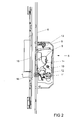
- FIG. 2 shows one of the automatic locks 5 in an unlocked position with a lock case shown open 8.
- a latch 9 is pivoted back completely in this unlocked position in the lock case 8 and is supported via an arm 10 on a biased by a torsion spring 11 button 12 from.
- a fixed in the lock case 8 spring element 13 biases the bolt 9 with the arm 10 against the button 12 in front. If the button 12 is depressed, this comes out of the range of movement of the arm 10 of the bolt 9 and releases the movement of the bolt 9 out of the lock case 8 out.
- the drive rod 6 is coupled to a slide 14 guided in the lock case 8.
- the lock case 8 is arranged in the wing 2 and is opposite to a fixed in the frame 1 strike plate 15.
- a arranged in the strike plate 15 control cam 16 is in a lowered basic position. In this basic position, the control cam 16 is not able to actuate the button 12.
- An automatic function, in which the bolt 9 is extended by the force of the spring element 13, is in the in FIG. 2 shown disabled position by the position of the control cam 16 in the normal position.
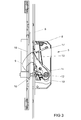
- the control cam 16 can be moved into a protruding release position in which he presses the button 12. This position is in FIG. 3 shown.
- the button 12 By pressing the button 12 via the control cam 16, the movement of the arm 10 of the bolt 9 and thus the bolt 9 is released itself.
- the bolt 9 snaps by the force of the spring element 13 from the lock case 8 out into the strike plate 15.
- the automatic lock 5 is thus in the locked position.
- the latch 9 is also engaged behind by a pivotable pawl 17.
- the slider 14 is used to drive the bolt 9 of the in FIG. 3 illustrated locked position in an unlocked position.
- the pawl 17 is pivoted and at the same time the latch 9 is pushed back into the lock case 8.
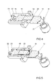
- FIG. 4 shows the button 12 and the control cam 16 in an enlarged perspective view.
- the control cam 16 is slidably disposed in a sleeve 18 connected to the closing plate 15 and by a spring element 19 in one in the range of movement of the probe 12 biased position and has at its the switch 12 side facing a magnet 20.
- the magnet 20 cooperates with the steel made lock case 8, so that when closing the in FIG. 1 shown door of the magnet 20 against the force of the spring element 19 from the retracted position in the in FIG. 3 shown triggering position is pulled.
- the button 12 has an angle 21 for supporting the arm 10 of the bolt 9. The angle 21 and the arm 10 thus form a trigger for selectively blocking or releasing the movement of the bolt. 9
- FIG. 5 shows the button 12 and the control cam 16 FIG. 4 when in basic position fixed control cam 16.
- the control cam 16 is rotatably disposed in the sleeve 18 and has at its end facing away from the button 12 a cross bar 22 which engages behind an elongated recess 23 in the bottom of the sleeve 18.
- the sleeve 18 is shown in section. Starting from the position FIG. 4 can the control cam 16 push with a suitable tool in the sleeve 18 and from the in FIG. 4 shown rotational position in the in FIG. 5 move shown rotational position.
- the control cam 16 is fixed in the sleeve 18 and an actuation of the button 12 when closing the door is omitted. This deactivates the automatic function of the automatic lock.
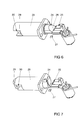
- FIG. 6 shows a further embodiment of a control cam 24 and a button 25. These differ from those FIGS. 4 and 5 especially in that the control cam 24 has a ramp 26, with which he presses the button 25 when closing the door.
- the control cam 24 is itself designed magnetically and can be arranged from a arranged on the lock case 8 and schematically illustrated here magnet 27 of a in Move a sleeve 28 located basic position in the illustrated release position.
- FIG. 6 is the control cam 24 with a cross bar 29 in a guide 30 of the sleeve 28. Pressed starting from the position FIG. 6 the control cam 24 into the sleeve 28, the crossbar 29 passes out of the guide 30 of the sleeve 28 out. Subsequently, the control cam 24 of the in FIG. 6 shown rotational position in the in FIG. 7 pivot position shown pivot, so that the cross bar 29 is fixed outside of the guide 30. This deactivates the automatic function of the automatic lock.
- control cam 16, 24 may also be arranged on the strike plate 15, a slider which is disposed in a position outside the range of movement of the control cam 16, 24 and can be pushed into a second position on the sleeve 18, 28.
- the control cam 16, 24 would also be fixed in a located in the sleeve 18, 28 basic position.
Landscapes
- Engineering & Computer Science (AREA)
- Mechanical Engineering (AREA)
- Structural Engineering (AREA)
- Lock And Its Accessories (AREA)
- Casings For Electric Apparatus (AREA)
- Closures For Containers (AREA)
Abstract
Description
- Die Erfindung betrifft ein Automatikschloss mit einem Schlosskasten und einem dem Schlosskasten gegenüberliegend anzuordnenden Schließblech, mit einem zwischen einer im Schlosskasten befindlichen Offenstellung in eine aus dem Schlosskasten herausragenden Schließstellung beweglichen Riegel und mit einem Taster zur Erfassung der Position eines mit dem Schließblech verbundenen Steuernockens, wobei der Taster in der Stellung, in der der Schlosskasten dem Schließblech gegenübersteht, von dem Schließblech beabstandet ist, und mit einem von dem Taster ansteuerbaren Auslöser zur Freigabe der Bewegung des Riegels von der Offenstellung in die Schließstellung.
- Solche Automatikschlösser ermöglichen eine selbständige Verriegelung, wenn eine damit ausgestattete Tür geschlossen wird. Die Automatikschlösser werden beispielsweise mit dem Schlosskasten, dem Riegel und dem Taster in einem Flügel einer Tür und das Schließblech in einem Rahmen befestigt. Im montierten Zustand wird der Taster beim Schließen des Flügels niedergedrückt und gibt die Bewegung des Riegels frei. Bei aus der Praxis bekannten Schlössern gleitet der Taster beim Schließen der Tür über das Schließblech und erzeugt damit störende Schleifspuren.
- Die
EP 1 158 126 B1 offenbart ein Schloss, bei dem der Steuernocken justierbar und dem Taster gegenüberstehend in dem Schließblech angeordnet ist. Durch die Ansteuerung des Tasters über den Steuernocken lässt sich vermeiden, dass der Taster über das Schließblech schleift und Schleifspuren erzeugt. Jedoch muss die Position des Steuernockens aufwändig justiert werden. Steht der Steuernocken zu weit von dem Schließblech ab, kann dies im ungünstigsten Fall dazu führen, dass der Steuernocken an dem Schlosskasten anstößt. - Der Erfindung liegt das Problem zugrunde, ein Automatikschloss der eingangs genannten Art so weiter zu bilden, dass Schleifspuren und eine aufwändige Einstellung des Steuernockens vermieden werden.
- Dieses Problem wird erfindungsgemäß dadurch gelöst, dass der Steuernocken beweglich gelagert ist und in einer Grundstellung in dem Schließblech zurückgezogen ist und in einer Auslösestellung in die Bewegungsrichtung des Tasters hineinragt und dass ein Magnet zur Bewegung des Steuernockens in die Auslösestellung vorgesehen ist.
- Durch diese Gestaltung wird der Steuernocken erst dann in die Auslösestellung bewegt, wenn sich der Schlosskasten über dem Schließblech befindet. Dabei gelangen Steuernocken und Taster aneinander, so dass der Taster die vorgesehene Funktion im Automatikschloss ausführen kann. Da der Steuernocken erst in der Position bewegt wird, in der er den Taster ansteuert, muss der Steuernocken dabei nicht justiert werden. Eine Berührung des Tasters an dem Schließblech wird dank der Erfindung zuverlässig vermieden. Daher entstehen auch keine Schleifspuren durch die Bewegung des Tasters. Weiterhin werden störende, von dem Schließblech hervorstehende Bauteile bei geöffnetem Flügel vermieden. Vorzugsweise ist der Steuernocken in einem einstückig mit einer Schließkante für den Riegel gefertigten Bauteil geführt, weil hierdurch die Auslöseposition des Tasters besonders genau festgelegt ist.
- Die Ansteuerung der Bewegung des Steuernockens gestaltet sich gemäß einer vorteilhaften Weiterbildung der Erfindung besonders einfach, wenn der Magnet in zumindest einem der Bauteile Taster oder Steuernocken angeordnet ist.
- Der Magnet kann gemäß einer anderen vorteilhaften Weiterbildung der Erfindung einfach nachträglich an vorhandenen Schlössern montiert werden, wenn der Magnet an den Schlosskasten angeordnet ist. Im einfachsten Fall kann eine den Schlosskasten abdeckende Stulpschiene magnetisch gestaltet sein.
- Die Bewegung des Magneten lässt sich gemäß einer anderen vorteilhaften Weiterbildung der Erfindung zuverlässig sicherstellen, wenn der Steuernocken von einem Federelement in der zurückgezogenen Stellung gehalten ist.
- Die Auslösung des Tasters gestaltet sich gemäß einer anderen vorteilhaften Weiterbildung der Erfindung besonders leichtgängig, wenn zumindest eines der Bauteile Steuernocken oder Taster eine in den Bewegungsbereich des anderen Bauteils hineinragende Auflauframpe hat.
- Die Automatikfunktion des erfindungsgemäßen Automatikschlosses lässt sich einfach aktivieren oder deaktivieren, wenn der Steuernocken in einer außerhalb des Bewegungsbereichs des Tasters befindlichen Grundstellung fixierbar ist. Durch diese Gestaltung wird die Betätigung des Tasters bei der Fixierung des Steuernockens in seiner Grundstellung verhindert, so dass der Riegel in diesem Fall nicht ausgefahren wird.
- Die Fixierung des Steuernockens in der Grundstellung gestaltet sich gemäß einer anderen vorteilhaften Weiterbildung der Erfindung konstruktiv besonders einfach, wenn der Steuernocken drehbar in einer Hülse gelagert ist und in einer Drehstellung axial verschieblich und in der anderen Drehstellung in der Grundstellung fixiert ist.
- Die Fixierung des Steuernockens in der Grundstellung gestaltet sich besonders komfortabel, wenn eine quer zur Bewegungsrichtung des Steuernockens verschiebbare Steuerleiste in einer ersten Stellung einen Formschluss mit dem in Grundstellung befindlichen Steuernocken erzeugt und in einer zweiten Stellung die Bewegung des Steuernockens freigibt. Vorzugsweise hat die Steuerleiste für die formschlüssige Verbindung mit dem Steuernocken einen Rand, welcher in Grundstellung in eine Nut des Steuernockens eindringt. Zur Verstellung der Steuerschiene eignet sich beispielsweise ein Exzenter. Die Steuerschiene kann dabei zur Ansteuerung mehrerer Steuernocken ausgebildet sein.
- Der bauliche Aufwand zur Führung des Steuernockens lässt sich gemäß einer anderen vorteilhaften Weiterbildung der Erfindung besonders gering halten, wenn der Steuernocken axial verschieblich in einer Hülse geführt ist.
- Die Erfindung lässt zahlreiche Ausführungsformen zu. Zur weiteren Verdeutlichung ihres Grundprinzips ist eine davon in der Zeichnung dargestellt und wird nachfolgend beschrieben. Diese zeigt in
- Fig. 1
- eine Tür mit einem erfindungsgemäßen Automatikschloss,
- Fig. 2
- vergrößert das Automatikschloss aus
Figur 1 in einer entriegelter Stellung, - Fig. 3
- das Automatikschloss aus
Figur 2 in verriegelter Stellung, - Fig. 4
- vergrößert einen Taster mit einem Steuernocken des Automatikschlosses aus
Figur 2 , - Fig. 5
- den Taster mit dem Steuernocken aus
Figur 4 in fixierter Stellung, - Fig. 6
- eine weitere Ausführungsform eines Tasters mit einem Steuernocken,
- Fig. 7
- den Taster mit dem Steuernocken aus
Figur 6 in fixierter Stellung. -
Figur 1 zeigt eine Tür mit einem gegen einen Rahmen 1 schwenkbaren Flügel 2 und mit einem Treibstangenschloss 3. Das Treibstangenschloss 3 hat ein Hauptschloss 4 und mehrere, als Nebenschlösser ausgebildete Automatikschlösser 5. Das Hauptschloss 4 ist über eine Treibstange 6 mit den Automatikschlössern 5 verbunden und hat eine schematisch dargestellte Antriebseinrichtung 7 zum Antrieb der Treibstange 6. Bei der Antriebseinrichtung 7 kann es sich um eine allgemein bekannte Handhabe, einen Schließzylinder und/oder einen motorischen Antrieb handeln. -
Figur 2 zeigt eines der Automatikschlösser 5 in einer entriegelten Stellung mit einem geöffnet dargestellten Schlosskasten 8. Ein Riegel 9 ist in dieser entriegelten Stellung vollständig in den Schlosskasten 8 zurückgeschwenkt und stützt sich über einen Arm 10 an einem von einer Drehfeder 11 vorgespannten Taster 12 ab. Ein in dem Schlosskasten 8 befestigtes Federelement 13 spannt den Riegel 9 mit dem Arm 10 gegen den Taster 12 vor. Wird der Taster 12 niedergedrückt, gelangt dieser aus dem Bewegungsbereich des Arms 10 des Riegels 9 heraus und gibt die Bewegung des Riegels 9 aus dem Schlosskasten 8 heraus frei. Die Treibstange 6 ist mit einem in dem Schlosskasten 8 geführten Schieber 14 gekoppelt. - Der Schlosskasten 8 ist in dem Flügel 2 angeordnet und steht einem in dem Rahmen 1 befestigten Schließblech 15 gegenüber. Ein in dem Schließblech 15 angeordneter Steuernocken 16 befindet sich in einer versenkten Grundstellung. In dieser Grundstellung vermag der Steuernocken 16 den Taster 12 nicht zu betätigen. Eine Automatikfunktion, bei der der Riegel 9 durch die Kraft des Federelementes 13 ausgefahren wird, ist in der in
Figur 2 dargestellten Stellung durch die Position des Steuernockens 16 in der Grundstellung deaktiviert. - Der Steuernocken 16 lässt sich in eine hervorstehende Auslösestellung bewegen, in der er den Taster 12 betätigt. Diese Stellung ist in
Figur 3 dargestellt. Durch die Betätigung des Tasters 12 über den Steuernocken 16 wird die Bewegung des Arms 10 des Riegels 9 und damit des Riegels 9 selbst freigegeben. Der Riegel 9 schnappt durch die Kraft des Federelementes 13 aus dem Schlosskasten 8 heraus in das Schließblech 15. Das Automatikschloss 5 befindet sich damit in der verriegelten Stellung. Der Riegel 9 wird zudem von einer schwenkbaren Sperrklinke 17 hintergriffen. - Der Schieber 14 dient zum Antrieb des Riegels 9 von der in
Figur 3 dargestellten verriegelten Stellung in eine entriegelte Stellung. Beim Antrieb des Schiebers 14 über die Treibstange 6 wird die Sperrklinke 17 verschwenkt und gleichzeitig der Riegel 9 in den Schlosskasten 8 zurückgedrückt. -
Figur 4 zeigt den Taster 12 und den Steuernocken 16 in einer vergrößerten perspektivischen Darstellung. Der Steuernocken 16 ist in einer mit dem Schließblech 15 verbundenen Hülse 18 verschieblich angeordnet und von einem Federelement 19 in eine in den Bewegungsbereich des Tasters 12 befindliche Stellung vorgespannt und hat an seiner dem Taster 12 zugewandten Seite einen Magneten 20. Der Magnet 20 wirkt mit dem aus Stahl gefertigten Schlosskasten 8 zusammen, so dass beim Schließen der inFigur 1 dargestellten Tür der Magnet 20 gegen die Kraft des Federelementes 19 aus der zurückgezogenen Stellung in die inFigur 3 dargestellte Auslösestellung gezogen wird. Der Taster 12 hat einen Winkel 21 zur Abstützung des Arms 10 des Riegels 9. Der Winkel 21 und der Arm 10 bilden damit einen Auslöser zur wahlweisen Blockierung oder Freigabe der Bewegung des Riegels 9. -
Figur 5 zeigt den Taster 12 und den Steuernocken 16 ausFigur 4 bei in Grundstellung fixiertem Steuernocken 16. Der Steuernocken 16 ist in der Hülse 18 drehbar angeordnet und hat an seinem dem Taster 12 abgewandten Ende einen Querriegel 22, welcher eine längliche Ausnehmung 23 im Boden der Hülse 18 hintergreift. Zur Verdeutlichung ist die Hülse 18 geschnitten dargestellt. Ausgehend von der Position ausFigur 4 lässt sich der Steuernocken 16 mit einem geeigneten Werkzeug in die Hülse 18 hineindrücken und von der inFigur 4 dargestellten Drehstellung in die inFigur 5 dargestellte Drehstellung bewegen. Damit ist der Steuernocken 16 in der Hülse 18 fixiert und eine Betätigung des Tasters 12 beim Schließen der Tür unterbleibt. Hierdurch wird die Automatikfunktion des Automatikschlosses deaktiviert. -
Figur 6 zeigt eine weitere Ausführungsform eines Steuernockens 24 und eines Tasters 25. Diese unterscheiden sich von denen ausFigur 4 und 5 vor allem dadurch, dass der Steuernocken 24 eine Auflauframpe 26 hat, mit der er beim Schließen der Tür den Taster 25 niederdrückt. Der Steuernocken 24 ist selbst magnetisch gestaltet und lässt sich von einem an dem Schlosskasten 8 angeordneten und hier schematisch dargestellten Magneten 27 aus einer in einer Hülse 28 befindlichen Grundstellung in die dargestellte Auslösestellung bewegen. InFigur 6 befindet sich der Steuernocken 24 mit einem Querriegel 29 in einer Führung 30 der Hülse 28. Drückt man ausgehend von der Stellung ausFigur 6 den Steuernocken 24 in die Hülse 28 hinein, gelangt der Querriegel 29 aus der Führung 30 der Hülse 28 heraus. Anschließend lässt sich der Steuernocken 24 von der inFigur 6 dargestellten Drehstellung in die inFigur 7 dargestellte Drehstellung verschwenken, so dass der Querriegel 29 außerhalb der Führung 30 fixiert ist. Damit wird die Automatikfunktion des Automatikschlosses deaktiviert. - In einer nicht dargestellten Ausführungsform kann an dem Schließblech 15 auch ein Schieber angeordnet sein, welcher in einer Stellung außerhalb des Bewegungsbereichs des Steuernockens 16, 24 angeordnet ist und sich in eine zweite Stellung über die Hülse 18, 28 schieben lässt. Damit wäre der Steuernocken 16, 24 ebenfalls in einer in der Hülse 18, 28 befindlichen Grundstellung fixiert.
Claims (9)
- Automatikschloss (5) mit einem Schlosskasten (8) und einem dem Schlosskasten (8) gegenüberliegend anzuordnenden Schließblech (15), mit einem zwischen einer im Schlosskasten (8) befindlichen Offenstellung in eine aus dem Schlosskasten (8) herausragenden Schließstellung beweglichen Riegel (9) und mit einem Taster (12, 25) zur Erfassung der Position eines mit dem Schließblech (15) verbundenen Steuernockens (16, 24), wobei der Taster (12, 25) in der Stellung, in der der Schlosskasten (8) dem Schließblech (15) gegenübersteht, von dem Schließblech (15) beabstandet ist, und mit einem von dem Taster (12, 25) ansteuerbaren Auslöser zur Freigabe der Bewegung des Riegels (9) von der Offenstellung in die Schließstellung, dadurch gekennzeichnet, dass der Steuernocken (16, 24) beweglich gelagert ist und in einer Grundstellung in dem Schließblech (15) zurückgezogen ist und in einer Auslösestellung in die Bewegungsrichtung des Tasters (12, 25) hineinragt und dass ein Magnet (20, 27) zur Bewegung des Steuernockens (16, 24) in die Auslösestellung vorgesehen ist.
- Automatikschloss nach Anspruch 1, dadurch gekennzeichnet, dass der Magnet (20) in zumindest einem der Bauteile Taster (12) oder Steuernocken (16) angeordnet ist.
- Automatikschloss nach Anspruch 1 oder 2, dadurch gekennzeichnet, dass der Magnet (27) an dem Schlosskasten (8) angeordnet ist.
- Automatikschloss nach einem der Ansprüche 1 bis 3, dadurch gekennzeichnet, dass der Steuernocken (16, 24) von einem Federelement (19) in der zurückgezogenen Stellung gehalten ist.
- Automatikschloss nach einem der Ansprüche 1 bis 4, dadurch gekennzeichnet, dass zumindest eines der Bauteile Steuernocken (24) oder Taster (25) eine in den Bewegungsbereich des anderen Bauteils hineinragende Auflauframpe (26) hat.
- Automatikschloss nach einem der Ansprüche 1 bis 5, dadurch gekennzeichnet, dass der Steuernocken (16, 24) in einer außerhalb des Bewegungsbereichs des Tasters (12, 25) befindlichen Grundstellung fixierbar ist.
- Automatikschloss nach Anspruch 6, dadurch gekennzeichnet, dass der Steuernocken (16, 24) drehbar in einer Hülse (18, 28) gelagert ist und in einer Drehstellung axial verschieblich und in der anderen Drehstellung in der Grundstellung fixiert ist.
- Automatikschloss nach Anspruch 6 oder 7, dadurch gekennzeichnet, dass eine quer zur Bewegungsrichtung des Steuernockens (16, 24) verschiebbare Steuerleiste in einer ersten Stellung einen Formschluss mit dem in Grundstellung befindlichen Steuernocken (16, 24) erzeugt und in einer zweiten Stellung die Bewegung des Steuernockens (16, 24) freigibt.
- Automatikschloss nach einem der Ansprüche 1 bis8, dadurch gekennzeichnet, dass der Steuernocken (16, 24) axial verschieblich in einer Hülse (18, 28) geführt ist.
Priority Applications (1)
| Application Number | Priority Date | Filing Date | Title |
|---|---|---|---|
| PL13155214T PL2634330T3 (pl) | 2012-02-28 | 2013-02-14 | Zamek automatyczny |
Applications Claiming Priority (1)
| Application Number | Priority Date | Filing Date | Title |
|---|---|---|---|
| DE102012203053A DE102012203053A1 (de) | 2012-02-28 | 2012-02-28 | Automatikschloss |
Publications (3)
| Publication Number | Publication Date |
|---|---|
| EP2634330A2 true EP2634330A2 (de) | 2013-09-04 |
| EP2634330A3 EP2634330A3 (de) | 2017-07-05 |
| EP2634330B1 EP2634330B1 (de) | 2019-12-18 |
Family
ID=47683647
Family Applications (1)
| Application Number | Title | Priority Date | Filing Date |
|---|---|---|---|
| EP13155214.3A Active EP2634330B1 (de) | 2012-02-28 | 2013-02-14 | Automatikschloss |
Country Status (3)
| Country | Link |
|---|---|
| EP (1) | EP2634330B1 (de) |
| DE (1) | DE102012203053A1 (de) |
| PL (1) | PL2634330T3 (de) |
Cited By (4)
| Publication number | Priority date | Publication date | Assignee | Title |
|---|---|---|---|---|
| ITUA20161698A1 (it) * | 2016-03-15 | 2017-09-15 | Alban Giacomo Spa | Sistema automatico di chiusura per serramenti |
| WO2020194089A1 (en) * | 2019-03-26 | 2020-10-01 | Alban Giacomo S.P.A. | Automatic system for closing windows or doors |
| CN116439934A (zh) * | 2023-04-24 | 2023-07-18 | 成都华信高科医疗器械有限责任公司 | 一种自动落锁机构的实现方法 |
| CN118430593A (zh) * | 2023-02-02 | 2024-08-02 | 慧与发展有限责任合伙企业 | 用于驱动器空板的集成锁定机构 |
Citations (1)
| Publication number | Priority date | Publication date | Assignee | Title |
|---|---|---|---|---|
| EP1158126B1 (de) | 1999-09-25 | 2004-06-30 | Karl Fliether GmbH & Co. KG | Schloss |
Family Cites Families (4)
| Publication number | Priority date | Publication date | Assignee | Title |
|---|---|---|---|---|
| DE3801441A1 (de) * | 1987-03-18 | 1988-09-29 | Bks Gmbh | Tuerschloss mit verriegelungselement und hilfsfalle |
| DE202005013991U1 (de) * | 2005-09-06 | 2007-01-18 | Kfv Karl Fliether Gmbh & Co. Kg | Fehlbedienungssperre für eine Treibstange |
| DE102008011551B4 (de) * | 2008-02-28 | 2013-01-17 | Carl Fuhr Gmbh & Co. Kg | Selbstverriegelnde Zusatzverriegelung |
| DE202009014455U1 (de) * | 2009-10-26 | 2010-02-11 | Kfv Karl Fliether Gmbh & Co. Kg | Treibstangensperre |
-
2012
- 2012-02-28 DE DE102012203053A patent/DE102012203053A1/de not_active Withdrawn
-
2013
- 2013-02-14 EP EP13155214.3A patent/EP2634330B1/de active Active
- 2013-02-14 PL PL13155214T patent/PL2634330T3/pl unknown
Patent Citations (1)
| Publication number | Priority date | Publication date | Assignee | Title |
|---|---|---|---|---|
| EP1158126B1 (de) | 1999-09-25 | 2004-06-30 | Karl Fliether GmbH & Co. KG | Schloss |
Cited By (6)
| Publication number | Priority date | Publication date | Assignee | Title |
|---|---|---|---|---|
| ITUA20161698A1 (it) * | 2016-03-15 | 2017-09-15 | Alban Giacomo Spa | Sistema automatico di chiusura per serramenti |
| WO2017158449A1 (en) * | 2016-03-15 | 2017-09-21 | Alban Giacomo S.P.A. | Automatic system for closing windows or doors |
| WO2020194089A1 (en) * | 2019-03-26 | 2020-10-01 | Alban Giacomo S.P.A. | Automatic system for closing windows or doors |
| EP3914792B1 (de) | 2019-03-26 | 2022-06-29 | Alban Giacomo S.p.A. | Automatisches system zum schliessen von fenstern oder türen |
| CN118430593A (zh) * | 2023-02-02 | 2024-08-02 | 慧与发展有限责任合伙企业 | 用于驱动器空板的集成锁定机构 |
| CN116439934A (zh) * | 2023-04-24 | 2023-07-18 | 成都华信高科医疗器械有限责任公司 | 一种自动落锁机构的实现方法 |
Also Published As
| Publication number | Publication date |
|---|---|
| EP2634330A3 (de) | 2017-07-05 |
| EP2634330B1 (de) | 2019-12-18 |
| DE102012203053A1 (de) | 2013-08-29 |
| PL2634330T3 (pl) | 2020-06-15 |
Similar Documents
| Publication | Publication Date | Title |
|---|---|---|
| DE10202088B4 (de) | Schloss | |
| EP2179116B1 (de) | Türschloss | |
| DE102016119515A1 (de) | Beschlag für eine Schiebetür, Schiebetüreinheit, Verfahren zum Öffnen einer Schiebetür und Verfahren zum Schließen einer Schiebetür | |
| EP2673434B1 (de) | Schloss mit einer falle und einer zusatzfalle zur ablaufsicherung einer riegelbewegung | |
| EP2634330A2 (de) | Automatikschloss | |
| AT513469B1 (de) | Türschloss | |
| EP3034728B1 (de) | Öffnungsbegrenzereinrichtung | |
| DE19848275C2 (de) | Vorrichtung zum Verriegeln einer Tür eines Haushaltsgerätes | |
| EP2666938B1 (de) | Schloss für eine tür | |
| DE102015000606A1 (de) | Verriegelungsvorrichtung für einen schwenkbar gelagerten Flügel | |
| EP2634331B1 (de) | Automatikschloss | |
| EP3112564A1 (de) | Selbstverriegelndes fallenschloss | |
| EP3091151A1 (de) | Treibstangensperre für einen treibstangenbeschlag | |
| EP3498942B1 (de) | Schloss | |
| EP1739257A1 (de) | Schloss | |
| DE10129349A1 (de) | Schloss | |
| DE202014009557U1 (de) | Schloss,insbesondere Glastürschloss | |
| EP2615229A2 (de) | Schließanlage | |
| EP3029233B1 (de) | Treibstangenschloss | |
| EP2696014B1 (de) | Automatikschloss | |
| EP1514986A2 (de) | Treibstangenschloss | |
| EP3498943B1 (de) | Schloss | |
| DE19626746C1 (de) | Selbstverriegelndes Panikschloß | |
| EP3447217B1 (de) | Treibstangenschloss | |
| DE10162194B4 (de) | Riegelwerksteuerung |
Legal Events
| Date | Code | Title | Description |
|---|---|---|---|
| PUAI | Public reference made under article 153(3) epc to a published international application that has entered the european phase |
Free format text: ORIGINAL CODE: 0009012 |
|
| AK | Designated contracting states |
Kind code of ref document: A2 Designated state(s): AL AT BE BG CH CY CZ DE DK EE ES FI FR GB GR HR HU IE IS IT LI LT LU LV MC MK MT NL NO PL PT RO RS SE SI SK SM TR |
|
| AX | Request for extension of the european patent |
Extension state: BA ME |
|
| PUAL | Search report despatched |
Free format text: ORIGINAL CODE: 0009013 |
|
| AK | Designated contracting states |
Kind code of ref document: A3 Designated state(s): AL AT BE BG CH CY CZ DE DK EE ES FI FR GB GR HR HU IE IS IT LI LT LU LV MC MK MT NL NO PL PT RO RS SE SI SK SM TR |
|
| AX | Request for extension of the european patent |
Extension state: BA ME |
|
| RIC1 | Information provided on ipc code assigned before grant |
Ipc: E05C 9/18 20060101ALN20170531BHEP Ipc: E05B 17/22 20060101ALI20170531BHEP Ipc: E05B 47/00 20060101ALI20170531BHEP Ipc: E05B 63/20 20060101AFI20170531BHEP |
|
| STAA | Information on the status of an ep patent application or granted ep patent |
Free format text: STATUS: REQUEST FOR EXAMINATION WAS MADE |
|
| 17P | Request for examination filed |
Effective date: 20171205 |
|
| RBV | Designated contracting states (corrected) |
Designated state(s): AL AT BE BG CH CY CZ DE DK EE ES FI FR GB GR HR HU IE IS IT LI LT LU LV MC MK MT NL NO PL PT RO RS SE SI SK SM TR |
|
| RIC1 | Information provided on ipc code assigned before grant |
Ipc: E05B 47/00 20060101ALI20190626BHEP Ipc: E05C 9/18 20060101ALI20190626BHEP Ipc: E05B 63/20 20060101AFI20190626BHEP |
|
| GRAP | Despatch of communication of intention to grant a patent |
Free format text: ORIGINAL CODE: EPIDOSNIGR1 |
|
| STAA | Information on the status of an ep patent application or granted ep patent |
Free format text: STATUS: GRANT OF PATENT IS INTENDED |
|
| INTG | Intention to grant announced |
Effective date: 20190802 |
|
| GRAS | Grant fee paid |
Free format text: ORIGINAL CODE: EPIDOSNIGR3 |
|
| GRAA | (expected) grant |
Free format text: ORIGINAL CODE: 0009210 |
|
| STAA | Information on the status of an ep patent application or granted ep patent |
Free format text: STATUS: THE PATENT HAS BEEN GRANTED |
|
| AK | Designated contracting states |
Kind code of ref document: B1 Designated state(s): AL AT BE BG CH CY CZ DE DK EE ES FI FR GB GR HR HU IE IS IT LI LT LU LV MC MK MT NL NO PL PT RO RS SE SI SK SM TR |
|
| REG | Reference to a national code |
Ref country code: GB Ref legal event code: FG4D Free format text: NOT ENGLISH |
|
| REG | Reference to a national code |
Ref country code: CH Ref legal event code: EP |
|
| REG | Reference to a national code |
Ref country code: DE Ref legal event code: R096 Ref document number: 502013014067 Country of ref document: DE |
|
| REG | Reference to a national code |
Ref country code: IE Ref legal event code: FG4D Free format text: LANGUAGE OF EP DOCUMENT: GERMAN |
|
| REG | Reference to a national code |
Ref country code: AT Ref legal event code: REF Ref document number: 1214761 Country of ref document: AT Kind code of ref document: T Effective date: 20200115 |
|
| REG | Reference to a national code |
Ref country code: NL Ref legal event code: FP |
|
| PG25 | Lapsed in a contracting state [announced via postgrant information from national office to epo] |
Ref country code: SE Free format text: LAPSE BECAUSE OF FAILURE TO SUBMIT A TRANSLATION OF THE DESCRIPTION OR TO PAY THE FEE WITHIN THE PRESCRIBED TIME-LIMIT Effective date: 20191218 Ref country code: LV Free format text: LAPSE BECAUSE OF FAILURE TO SUBMIT A TRANSLATION OF THE DESCRIPTION OR TO PAY THE FEE WITHIN THE PRESCRIBED TIME-LIMIT Effective date: 20191218 Ref country code: NO Free format text: LAPSE BECAUSE OF FAILURE TO SUBMIT A TRANSLATION OF THE DESCRIPTION OR TO PAY THE FEE WITHIN THE PRESCRIBED TIME-LIMIT Effective date: 20200318 Ref country code: FI Free format text: LAPSE BECAUSE OF FAILURE TO SUBMIT A TRANSLATION OF THE DESCRIPTION OR TO PAY THE FEE WITHIN THE PRESCRIBED TIME-LIMIT Effective date: 20191218 Ref country code: GR Free format text: LAPSE BECAUSE OF FAILURE TO SUBMIT A TRANSLATION OF THE DESCRIPTION OR TO PAY THE FEE WITHIN THE PRESCRIBED TIME-LIMIT Effective date: 20200319 Ref country code: BG Free format text: LAPSE BECAUSE OF FAILURE TO SUBMIT A TRANSLATION OF THE DESCRIPTION OR TO PAY THE FEE WITHIN THE PRESCRIBED TIME-LIMIT Effective date: 20200318 Ref country code: LT Free format text: LAPSE BECAUSE OF FAILURE TO SUBMIT A TRANSLATION OF THE DESCRIPTION OR TO PAY THE FEE WITHIN THE PRESCRIBED TIME-LIMIT Effective date: 20191218 |
|
| REG | Reference to a national code |
Ref country code: LT Ref legal event code: MG4D |
|
| PG25 | Lapsed in a contracting state [announced via postgrant information from national office to epo] |
Ref country code: HR Free format text: LAPSE BECAUSE OF FAILURE TO SUBMIT A TRANSLATION OF THE DESCRIPTION OR TO PAY THE FEE WITHIN THE PRESCRIBED TIME-LIMIT Effective date: 20191218 Ref country code: RS Free format text: LAPSE BECAUSE OF FAILURE TO SUBMIT A TRANSLATION OF THE DESCRIPTION OR TO PAY THE FEE WITHIN THE PRESCRIBED TIME-LIMIT Effective date: 20191218 |
|
| PG25 | Lapsed in a contracting state [announced via postgrant information from national office to epo] |
Ref country code: AL Free format text: LAPSE BECAUSE OF FAILURE TO SUBMIT A TRANSLATION OF THE DESCRIPTION OR TO PAY THE FEE WITHIN THE PRESCRIBED TIME-LIMIT Effective date: 20191218 |
|
| PG25 | Lapsed in a contracting state [announced via postgrant information from national office to epo] |
Ref country code: CZ Free format text: LAPSE BECAUSE OF FAILURE TO SUBMIT A TRANSLATION OF THE DESCRIPTION OR TO PAY THE FEE WITHIN THE PRESCRIBED TIME-LIMIT Effective date: 20191218 Ref country code: RO Free format text: LAPSE BECAUSE OF FAILURE TO SUBMIT A TRANSLATION OF THE DESCRIPTION OR TO PAY THE FEE WITHIN THE PRESCRIBED TIME-LIMIT Effective date: 20191218 Ref country code: EE Free format text: LAPSE BECAUSE OF FAILURE TO SUBMIT A TRANSLATION OF THE DESCRIPTION OR TO PAY THE FEE WITHIN THE PRESCRIBED TIME-LIMIT Effective date: 20191218 Ref country code: PT Free format text: LAPSE BECAUSE OF FAILURE TO SUBMIT A TRANSLATION OF THE DESCRIPTION OR TO PAY THE FEE WITHIN THE PRESCRIBED TIME-LIMIT Effective date: 20200513 |
|
| PG25 | Lapsed in a contracting state [announced via postgrant information from national office to epo] |
Ref country code: SK Free format text: LAPSE BECAUSE OF FAILURE TO SUBMIT A TRANSLATION OF THE DESCRIPTION OR TO PAY THE FEE WITHIN THE PRESCRIBED TIME-LIMIT Effective date: 20191218 Ref country code: SM Free format text: LAPSE BECAUSE OF FAILURE TO SUBMIT A TRANSLATION OF THE DESCRIPTION OR TO PAY THE FEE WITHIN THE PRESCRIBED TIME-LIMIT Effective date: 20191218 Ref country code: IS Free format text: LAPSE BECAUSE OF FAILURE TO SUBMIT A TRANSLATION OF THE DESCRIPTION OR TO PAY THE FEE WITHIN THE PRESCRIBED TIME-LIMIT Effective date: 20200418 |
|
| REG | Reference to a national code |
Ref country code: DE Ref legal event code: R097 Ref document number: 502013014067 Country of ref document: DE |
|
| REG | Reference to a national code |
Ref country code: CH Ref legal event code: PL |
|
| PLBE | No opposition filed within time limit |
Free format text: ORIGINAL CODE: 0009261 |
|
| STAA | Information on the status of an ep patent application or granted ep patent |
Free format text: STATUS: NO OPPOSITION FILED WITHIN TIME LIMIT |
|
| REG | Reference to a national code |
Ref country code: BE Ref legal event code: MM Effective date: 20200229 |
|
| PG25 | Lapsed in a contracting state [announced via postgrant information from national office to epo] |
Ref country code: MC Free format text: LAPSE BECAUSE OF FAILURE TO SUBMIT A TRANSLATION OF THE DESCRIPTION OR TO PAY THE FEE WITHIN THE PRESCRIBED TIME-LIMIT Effective date: 20191218 Ref country code: DK Free format text: LAPSE BECAUSE OF FAILURE TO SUBMIT A TRANSLATION OF THE DESCRIPTION OR TO PAY THE FEE WITHIN THE PRESCRIBED TIME-LIMIT Effective date: 20191218 Ref country code: LU Free format text: LAPSE BECAUSE OF NON-PAYMENT OF DUE FEES Effective date: 20200214 Ref country code: ES Free format text: LAPSE BECAUSE OF FAILURE TO SUBMIT A TRANSLATION OF THE DESCRIPTION OR TO PAY THE FEE WITHIN THE PRESCRIBED TIME-LIMIT Effective date: 20191218 |
|
| 26N | No opposition filed |
Effective date: 20200921 |
|
| PG25 | Lapsed in a contracting state [announced via postgrant information from national office to epo] |
Ref country code: SI Free format text: LAPSE BECAUSE OF FAILURE TO SUBMIT A TRANSLATION OF THE DESCRIPTION OR TO PAY THE FEE WITHIN THE PRESCRIBED TIME-LIMIT Effective date: 20191218 Ref country code: CH Free format text: LAPSE BECAUSE OF NON-PAYMENT OF DUE FEES Effective date: 20200229 Ref country code: LI Free format text: LAPSE BECAUSE OF NON-PAYMENT OF DUE FEES Effective date: 20200229 |
|
| PG25 | Lapsed in a contracting state [announced via postgrant information from national office to epo] |
Ref country code: IT Free format text: LAPSE BECAUSE OF FAILURE TO SUBMIT A TRANSLATION OF THE DESCRIPTION OR TO PAY THE FEE WITHIN THE PRESCRIBED TIME-LIMIT Effective date: 20191218 Ref country code: IE Free format text: LAPSE BECAUSE OF NON-PAYMENT OF DUE FEES Effective date: 20200214 |
|
| PG25 | Lapsed in a contracting state [announced via postgrant information from national office to epo] |
Ref country code: BE Free format text: LAPSE BECAUSE OF NON-PAYMENT OF DUE FEES Effective date: 20200229 |
|
| PG25 | Lapsed in a contracting state [announced via postgrant information from national office to epo] |
Ref country code: TR Free format text: LAPSE BECAUSE OF FAILURE TO SUBMIT A TRANSLATION OF THE DESCRIPTION OR TO PAY THE FEE WITHIN THE PRESCRIBED TIME-LIMIT Effective date: 20191218 Ref country code: MT Free format text: LAPSE BECAUSE OF FAILURE TO SUBMIT A TRANSLATION OF THE DESCRIPTION OR TO PAY THE FEE WITHIN THE PRESCRIBED TIME-LIMIT Effective date: 20191218 Ref country code: CY Free format text: LAPSE BECAUSE OF FAILURE TO SUBMIT A TRANSLATION OF THE DESCRIPTION OR TO PAY THE FEE WITHIN THE PRESCRIBED TIME-LIMIT Effective date: 20191218 |
|
| PG25 | Lapsed in a contracting state [announced via postgrant information from national office to epo] |
Ref country code: MK Free format text: LAPSE BECAUSE OF FAILURE TO SUBMIT A TRANSLATION OF THE DESCRIPTION OR TO PAY THE FEE WITHIN THE PRESCRIBED TIME-LIMIT Effective date: 20191218 |
|
| P01 | Opt-out of the competence of the unified patent court (upc) registered |
Effective date: 20230512 |
|
| REG | Reference to a national code |
Ref country code: DE Ref legal event code: R081 Ref document number: 502013014067 Country of ref document: DE Owner name: AUG. WINKHAUS SE & CO. KG, DE Free format text: FORMER OWNER: AUG. WINKHAUS GMBH & CO. KG, 48291 TELGTE, DE Ref country code: DE Ref legal event code: R081 Ref document number: 502013014067 Country of ref document: DE Owner name: AUG. WINKHAUS SE, DE Free format text: FORMER OWNER: AUG. WINKHAUS GMBH & CO. KG, 48291 TELGTE, DE |
|
| PGFP | Annual fee paid to national office [announced via postgrant information from national office to epo] |
Ref country code: NL Payment date: 20250220 Year of fee payment: 13 |
|
| PGFP | Annual fee paid to national office [announced via postgrant information from national office to epo] |
Ref country code: PL Payment date: 20250131 Year of fee payment: 13 |
|
| REG | Reference to a national code |
Ref country code: DE Ref legal event code: R081 Ref document number: 502013014067 Country of ref document: DE Owner name: AUG. WINKHAUS SE, DE Free format text: FORMER OWNER: AUG. WINKHAUS SE & CO. KG, 48291 TELGTE, DE |
|
| PGFP | Annual fee paid to national office [announced via postgrant information from national office to epo] |
Ref country code: GB Payment date: 20260219 Year of fee payment: 14 |
|
| PGFP | Annual fee paid to national office [announced via postgrant information from national office to epo] |
Ref country code: DE Payment date: 20260217 Year of fee payment: 14 |
|
| PGFP | Annual fee paid to national office [announced via postgrant information from national office to epo] |
Ref country code: AT Payment date: 20260216 Year of fee payment: 14 |
|
| PGFP | Annual fee paid to national office [announced via postgrant information from national office to epo] |
Ref country code: FR Payment date: 20260219 Year of fee payment: 14 |