EP3914792B1 - Automatisches system zum schliessen von fenstern oder türen - Google Patents
Automatisches system zum schliessen von fenstern oder türen Download PDFInfo
- Publication number
- EP3914792B1 EP3914792B1 EP20706377.7A EP20706377A EP3914792B1 EP 3914792 B1 EP3914792 B1 EP 3914792B1 EP 20706377 A EP20706377 A EP 20706377A EP 3914792 B1 EP3914792 B1 EP 3914792B1
- Authority
- EP
- European Patent Office
- Prior art keywords
- leaf
- lock body
- switch
- closing
- counter
- Prior art date
- Legal status (The legal status is an assumption and is not a legal conclusion. Google has not performed a legal analysis and makes no representation as to the accuracy of the status listed.)
- Active
Links
- 230000005291 magnetic effect Effects 0.000 claims description 121
- 230000009471 action Effects 0.000 claims description 50
- 230000004913 activation Effects 0.000 claims description 23
- 230000000717 retained effect Effects 0.000 claims description 19
- 230000006641 stabilisation Effects 0.000 claims description 16
- 238000011105 stabilization Methods 0.000 claims description 16
- 238000013459 approach Methods 0.000 claims description 9
- 230000003993 interaction Effects 0.000 claims description 7
- 230000005294 ferromagnetic effect Effects 0.000 claims description 5
- 230000003213 activating effect Effects 0.000 claims description 3
- 230000000694 effects Effects 0.000 claims description 3
- 239000000696 magnetic material Substances 0.000 claims description 3
- 230000000284 resting effect Effects 0.000 claims description 3
- 238000001994 activation Methods 0.000 description 18
- 230000007246 mechanism Effects 0.000 description 11
- 239000003302 ferromagnetic material Substances 0.000 description 3
- 230000004907 flux Effects 0.000 description 3
- 238000006073 displacement reaction Methods 0.000 description 2
- 230000001419 dependent effect Effects 0.000 description 1
- 238000012423 maintenance Methods 0.000 description 1
Images


Classifications
-
- E—FIXED CONSTRUCTIONS
- E05—LOCKS; KEYS; WINDOW OR DOOR FITTINGS; SAFES
- E05B—LOCKS; ACCESSORIES THEREFOR; HANDCUFFS
- E05B63/00—Locks or fastenings with special structural characteristics
- E05B63/0013—Locks with rotary bolt without provision for latching
-
- E—FIXED CONSTRUCTIONS
- E05—LOCKS; KEYS; WINDOW OR DOOR FITTINGS; SAFES
- E05B—LOCKS; ACCESSORIES THEREFOR; HANDCUFFS
- E05B47/00—Operating or controlling locks or other fastening devices by electric or magnetic means
- E05B47/0038—Operating or controlling locks or other fastening devices by electric or magnetic means using permanent magnets
-
- E—FIXED CONSTRUCTIONS
- E05—LOCKS; KEYS; WINDOW OR DOOR FITTINGS; SAFES
- E05B—LOCKS; ACCESSORIES THEREFOR; HANDCUFFS
- E05B47/00—Operating or controlling locks or other fastening devices by electric or magnetic means
- E05B47/0046—Electric or magnetic means in the striker or on the frame; Operating or controlling the striker plate
-
- E—FIXED CONSTRUCTIONS
- E05—LOCKS; KEYS; WINDOW OR DOOR FITTINGS; SAFES
- E05B—LOCKS; ACCESSORIES THEREFOR; HANDCUFFS
- E05B63/00—Locks or fastenings with special structural characteristics
- E05B63/18—Locks or fastenings with special structural characteristics with arrangements independent of the locking mechanism for retaining the bolt or latch in the retracted position
- E05B63/20—Locks or fastenings with special structural characteristics with arrangements independent of the locking mechanism for retaining the bolt or latch in the retracted position released automatically when the wing is closed
-
- E—FIXED CONSTRUCTIONS
- E05—LOCKS; KEYS; WINDOW OR DOOR FITTINGS; SAFES
- E05B—LOCKS; ACCESSORIES THEREFOR; HANDCUFFS
- E05B17/00—Accessories in connection with locks
- E05B17/22—Means for operating or controlling lock or fastening device accessories, i.e. other than the fastening members, e.g. switches, indicators
-
- E—FIXED CONSTRUCTIONS
- E05—LOCKS; KEYS; WINDOW OR DOOR FITTINGS; SAFES
- E05B—LOCKS; ACCESSORIES THEREFOR; HANDCUFFS
- E05B63/00—Locks or fastenings with special structural characteristics
- E05B63/04—Locks or fastenings with special structural characteristics for alternative use on the right-hand or left-hand side of wings
-
- E—FIXED CONSTRUCTIONS
- E05—LOCKS; KEYS; WINDOW OR DOOR FITTINGS; SAFES
- E05C—BOLTS OR FASTENING DEVICES FOR WINGS, SPECIALLY FOR DOORS OR WINDOWS
- E05C19/00—Other devices specially designed for securing wings, e.g. with suction cups
- E05C19/16—Devices holding the wing by magnetic or electromagnetic attraction
Definitions
- the object of the present invention is an automatic locking system for windows or doors.
- the invention relates to the technical field of automatic closing systems of doors and windows of buildings and refers to automatic closing systems of a magnetic type.
- the aim of automatic closing systems is to guarantee that the bolts, also known as "closing points", of a lock installed on a door or window leaf automatically engage, i.e. without the intervention of the user, in special seatings fashioned on the fixed frame of the door or window, when the door or window leaf is in an aligned position to the frame.
- automatic closing systems comprise a lock body installed on a door or window leaf of the door or window and a counter-plate, commonly known as a "strike-plate", installed on a fixed frame of the door or window.
- the lock body is provided with bolts, also known as “hooks” or “closing points”, which, when the door or window leaf is in an aligned position to the frame, are released and automatically exit from suitable openings fashioned on the lock body, in order to engage in the counter-plate.
- a mobile magnet housed in the counter-plate is attracted by the ferromagnetic face-plate of the lock body and exits so as to press a projecting button installed on said face-plate.
- the button is mechanically connected to an unlocking mechanism for releasing the bolts. Therefore, when the door or window leaf and the frame are aligned, the pressure on the button by the magnet activates the unlocking mechanism, causing the release of the bolts and determining the automatic closing of the door or window.
- the opening of the door or window occurs by action of a recall mechanism, for example a leverage connected to a handle, which disengages the bolts from the counter-plate.
- suitable recall means acts on the magnet to cause the magnet to return into the counter-plate; at the same time, said recall means also acts on the unlocking mechanism in order to reposition the unlocking mechanism so that it locks the bolts in a retained condition inside the lock body. In this situation the door or window leaf is distanced from the frame and the door or window is open.
- the presence of an element (the button) projecting from the face-plate of the lock body compromises the safety of the closing system.
- this element if this element is accidentally or deliberately pushed, it activates the unlocking mechanism and causes the release of the bolts, also in the non-aligned condition between the door or window leaf and the frame, with the consequence that the bolts do not engage in the counter-plate and therefore do not determine the closing of the door or window.
- this first prior art disadvantageously functions only with lock bodies having a face-plate made of a ferromagnetic material.
- closing systems exist in which the unlocking mechanism forms a single part with a first magnet which, when the door or window leaf is aligned to the frame, is attracted by a second magnet housed in the counter-plate and arranged in a facing position to a face-plate of the lock body.
- the attraction of the first magnet towards the second magnet determines a displacement of the unlocking mechanism, causing the release of the bolts and determining the automatic closing of the door or window.
- the unlocking mechanism To enable the release of the bolts, it is indispensable for the unlocking mechanism to have a displacement stroke that is sufficient for releasing the release mechanism; therefore, the first magnet is housed in the lock body in a very retracted position with respect to a face-plate thereof, typically at least at about 4 mm from an external surface thereof.
- WO2017/158449 describes a closing system in accordance with this second prior art in which the second magnet is slidably housed in the counter-plate and, when the door or window leaf is aligned with the fixed frame and the lock body is facing the counter-plate, the second magnet is attracted by a third magnet, rigidly fixed to the lock body, and approaches the first magnet.
- the closing system is able to operate independently of the distance between the lock body and counter-plate.
- the activation of the unlocking mechanism and therefore the release of the bolts can also occur in the condition of imperfect alignment between the door or window leaf and the frame, with the consequence that the bolts do not engage in the counter-plate and therefore do not determine the closing of the door or window.
- Other examples of automatic systems for closing windows and doors are described in EP2634330 , DE8704036 , GB1009996 and US7308737 .
- an object of the present invention is to make available an automatic closing system for windows or doors, which is reliable and secure, i.e. able to prevent accidental exiting of the bolts, or closing points.
- “Closing step” is intended as the movement of the window or door leaf from an open position, in which the window or door leaf is not aligned with the fixed frame, towards a closed position, in which the leaf is aligned with the fixed frame.
- “Approaching step” is intended as that part of the closing step starting from when the lock body starts to face the counter-plate and ending when the window or door is fully closed, i.e. when the window or door leaf and the fixed frame are aligned and the lock body is completely facing the counter-plate.
- the approaching step is divided into an initial approaching step, starting from when the lock body starts facing the counter-plate until the lock body is partially facing the counter-plate, and a final approaching step, starting from when the lock body is partially facing the counter-plate until the window or door leaf and the fixed frame are aligned and the lock body is completely facing the counter-plate.
- Opening side of the window or door is intended as the side facing in the direction of opening of the leaf.
- the opening side corresponds to the side which, in the closing step, last faces the fixed frame or the components of the closing system mounted on the fixed frame.
- the opening side corresponds to the side which, in the closing step, first faces the window or door leaf or components of the closing system fitted on the leaf.
- “Closing side” of the window or door is intended as the side facing in the direction of closing of the window or door leaf.
- the closing side corresponds to the side which, in the closing step, first faces the fixed frame or components of the closing system mounted on the fixed frame.
- the closing side corresponds to the side which, in the closing step, last faces the window or door leaf or components of the closing system fitted on the leaf.
- the automatic closing system comprises a counter-plate, installable on a fixed frame and provided with a first member, and a lock body, installable on a door or window leaf and having a front portion intended to face the counter-plate when the door or window leaf is aligned with the fixed frame.
- the lock body is provided with closing means movable between a release configuration, in which the closing means engages the counter-plate, and a retained configuration, in which the closing means is maintained inside the lock body and does not engage the counter-plate.
- a switch is mounted in the lock body which is configured to assume a locking configuration wherein the switch locks the closing means in the retained configuration and an unlocking configuration wherein the switch unlocks the closing means, thereby activating the automatic movement of the closing means from the retained configuration to the release configuration.
- the switch and the first member are configured to exchange an activation magnetic-type action adapted to switch the switch from the locking configuration to the unlocking configuration only in a final approaching step of the lock body with respect to the counter-plate, which is a part of a closing step starting from when the lock body is partially facing the counter-plate and ending when the lock body is completely facing the counter-plate.
- the switch has a first leaf-side magnetic pole active at the front portion of the lock body.
- the first member also has a frame-side magnetic pole active at a front portion of the counter-plate.
- These first magnetic poles are configured in such a way as to generate the activation magnetic-type action only in the final approaching step.
- the first leaf-side magnetic pole is active only on an opening side so as to magnetically interact with the first frame-side magnetic pole only in the final approaching step of the lock body to the counter-plate and exchange the activation magnetic-type action.
- the first magnetic poles are configured so as to generate the activation magnetic-type action only in the final closing step of the lock body with respect to the counter-plate.
- the switch and the first member are configured to exchange a stabilization magnetic-type action adapted to maintain the switch in the locking configuration at least in an initial approaching step of the lock body with respect to the counter-plate which is a part of the closing step starting from when the lock body starts to face the counter-plate and ending when the lock body is partially facing the counter-plate.
- the activation magnetic-type action and the stabilization magnetic-type action are opposite. Still more preferably the activation magnetic-type action is an attractive action and the stabilization magnetic-type action is a repulsive action.
- the switch has a second leaf-side magnetic pole having opposite polarity to the polarity of the first leaf-side magnetic pole.
- the second leaf-side magnetic pole is active at the front portion of the lock body and only on a closing side.
- the first frame-side magnetic pole extends so as to magnetically interact with the second leaf-side magnetic pole at least in the initial approaching step, exchanging the stabilization magnetic-type action, and so as to magnetically interact with the first leaf-side magnetic pole only in the final approaching step, exchanging the activation magnetic-type action.
- the switch is adjustable to reverse the position of the first leaf-side magnetic pole and the second leaf-side magnetic pole on the plane of the front portion of the lock body.
- the switch is movable between a locking position, corresponding to the locking configuration, and an unlocking position, corresponding to the unlocking configuration. Still more preferably the switch is defined by a locking pin axially slidable between the locking position and the unlocking position.
- the locking pin preferably made of a non-magnetic material, preferably comprises a permanent magnet arranged along the longitudinal axis and having opposite poles active on opposite sides of the same longitudinal axis and two ferromagnetic elements adjacent to the permanent magnet arranged respectively on a closing side and on an opening side and respectively defining a first leaf-side magnetic pole and a second leaf-side magnetic pole as an effect of the interaction with the permanent magnet.
- the locking pin is rotatable about the longitudinal axis to reverse the position of the first leaf-side magnetic pole and the second leaf-side magnetic pole on the plane of the front portion of the lock body.
- the first member is movable with respect to the counter-plate.
- a second member distinct and separate from the switch, is integrally fixed to the lock body in such a way that, when the leaf is aligned with the fixed frame, the second member exercises an attraction force of a magnetic type on the first member which approaches the first member to the lock body in such a way that it magnetically interacts with the switch to activate the automatic switching of the closing means from the retained configuration to the release configuration.
- the second member is arranged at the front portion of the lock body.
- the first member is movable, for example slidably or rotatably, between a retracted configuration in which the first member is retracted inside a housing of the counter-plate and an extracted configuration in which the first member is extracted from the housing, to approach the switch.
- the first member when in the extracted configuration, is in a resting condition, even indirectly, against an edge surface forming part of the lock body, at the switch.
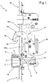
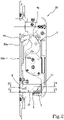
- an automatic closing system for windows or doors is denoted in its entirety by number 1.
- a door or window 100 is shown comprising a door or window leaf 101 and a fixed frame 102.
- the system 1 comprises a counter-plate 2 installable on the fixed frame 102 and having an opening 2a, a housing 2b and a front portion 2c.
- the counter-plate 2 is provided with a first member 3, preferably a first magnetic member 3, housed in the housing 2b.
- the first member 3 is defined by a permanent-type magnet.
- the permanent magnet of the first member 3 has a first frame-side magnetic pole 3a, active on the front portion 2c of the counter-plate 2. In the specific example illustrated in the accompanying drawings this first frame-side magnetic pole 3a is shown as a south pole.
- the first magnetic member 3 is preferably movable with respect to the counter-plate 2, and in particular with respect to the housing 2b, between a retracted configuration in which the first member is retracted inside the housing 2b of the counter-plate 2 and an extracted configuration in which the first member is extracted from the housing 2b to approach a switch 5 housed in the lock body 20. Still more preferably the first magnetic member 3 is slidably movable.
- the counter-plate can be made of a ferromagnetic material or a non-ferromagnetic material.
- the system 1 comprises a lock body 20 installable on the door or window leaf 101, having an opening 20a and a front portion 20b intended to face the counter-plate 2 when the door or window leaf is aligned with the fixed frame.
- the lock body 20 is provided with closing means 4.
- the closing means 4 is movable between a release configuration ( figure 1 ), in which it engages the counter-plate 2, and a retained configuration ( figure 2 ), in which it is maintained inside the lock body 20 and does not engage the counter-plate.
- the closing means preferably comprises a hook 4a which has a hooked portion 4b suitable for being inserted in the opening 2a of the counter-plate 2, engaging the same counter-plate.
- the system 1 comprises a switch 5 housed in the lock body 20.
- the switch 5 is configured to assume a locking configuration, wherein the switch 5 locks the closing means 4 in the retained configuration, and an unlocking configuration wherein the switch unlocks the closing means 4, thereby activating the automatic movement of the same closing means from the retained configuration ( figure 2 ) to the release configuration ( figure 1 ).
- the switch 5 activates the release of the hook 4, which, passing through an opening 20a of the lock body 20 and the opening 2a of the counter-plate 2, hooks the hooked portion 4b of the same counter-plate.
- the switch 5 is movable, for example slidable, between a locking position, corresponding to the locking configuration, and an unlocking position, corresponding to the unlocking configuration.
- the switch 5 can be housed completely inside the lock body 20 to prevent accidental activations, or tampering, of the closing system, ensuring the security of the door or window.
- the first magnetic member 3 magnetically interacts with the switch 5 to activate the switching thereof from the locking configuration to the unlocking configuration and cause the automatic passage of the closing means 4 from the retained configuration ( figure 2 ) to the release configuration ( figure 1 ).
- the first magnetic member 3 magnetically interacts with the switch 5 to bring it from the locked position to the unlocked position.
- the system 1 can comprise a second member 6, preferably a second magnetic member 6, integrally fixed to the lock body 20 so that when the door or window leaf is approached to the fixed frame, the second magnetic member 6 exercises a force of attraction on the first magnetic member 3 to bring it into the extracted configuration, i.e. to approach it to the lock body 20.
- the second member 6 is preferably defined by a permanent-type magnet.
- the second magnetic member 6 is arranged at the front portion 20b of the lock body 20 intended to face the counter-plate 2.
- the permanent magnet of the second member 6 has a magnetic pole active on the front portion 20b of the lock body 20, for example a north pole.
- the fixed, second magnetic member 6 attracts the movable, first magnetic member 3 so as to approach it to the switch 5 to activate the release of the closing means which lock the door or window, as will be described in the continuation of the present description.
- the switch 5 is distinct and separate from the second magnetic member 6. This circumstance advantageously enables optimising both the functioning of the switch and the positioning of the second magnetic member, since the second magnetic member is most effective in a flush or projecting position with respect to the front portion of the lock body, while the switch is best housed in the lock body for reasons of security.
- the switch 5 and the second magnetic member 6 can be installed on a same support 7.
- the presence of the support advantageously gives compactness to the closing system and simplifies the maintenance operations, as it is able to remove, with a single operation, both the functional elements of the lock body, i.e. the switch and the second magnetic member.
- the first magnetic member 3, when in the extracted configuration, is preferably in a contact configuration, including indirect contact, against an edge surface forming part of the lock body, at the switch.
- Indirect contact means that the first magnetic member can rest on the aforesaid edge surface also by means of interposition of another member, for example a surface of a containing tray of the first magnetic member.
- This edge surface can be for example the front portion 20b of the lock body 20 or, as shown in the figures, the support 7.
- recall means 8 is present for returning the first magnetic member 3 into the retracted configuration inside the housing 2b, when the lock body 20 is distanced from the counter-plate 2, i.e. when the door or window leaf is not aligned to the fixed frame.
- the recall means 8 preferably comprises an elastic element 9.
- the recall means comprises a ferromagnetic component conformed so as to exercise a force of attraction on the first magnetic member of a smaller entity with respect to the force of attraction which the second magnetic member exercises on the first magnetic member, when the door or window leaf is aligned to the fixed frame.
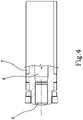
- the switch 5 is defined by a locking pin 10 which has a longitudinal axis "X" along which it slides axially between the locking position, preferably retracted in the lock body 20 and corresponding to the retained configuration of the closing means 4, and the unlocking position, preferably extracted from the lock body 20 and corresponding to the release configuration of the closing means.
- the locking pin 10 is associated with an elastic recall member 11, typically a helical spring, which returns it to the locked condition, when the door or window leaf is distanced from the frame, according to that which will be more fully described in the following paragraphs.
- an elastic recall member 11 typically a helical spring
- the locking pin 10 is preferably made of non-magnetic material and comprises a permanent magnet 12 arranged along the longitudinal axis "X" and having opposite poles active on opposite sides of the same longitudinal axis.
- L1 denotes an opening side of the door or window and L2 denotes a closing side of the door or window.
- the north pole of the permanent magnet 12 is active and on the closing side L2 the south pole of the permanent magnet 12 is active.
- Two ferromagnetic elements 13a, 13b are adjacent to the permanent magnet 12, arranged to contact respectively on the opening side L1 and on the closing side L2 and respectively defining a first leaf-side magnetic pole 14a and a second leaf-side magnetic pole 14b as an effect of the interaction with the permanent magnet 12.
- first leaf-side magnetic pole 14a is the north pole
- second leaf-side magnetic pole 14b is the south pole.
- the first leaf-side magnetic pole 14a is active on the opening side L1 and the second leaf-side magnetic pole 14b is active on the closing side L2. Moreover the first leaf-side magnetic pole 14a and the second leaf-side magnetic pole 14b are active at the front portion 20b of the lock body 20.
- the locking pin 10 is rotatable about the longitudinal axis "X" (arrow R of figure 3 ) to reverse the position of the first leaf-side magnetic pole 14a and the second leaf-side magnetic pole 14b on the plane of the front portion 20b of the lock body 20
- the locking pin 10 is rotatable 180° about the longitudinal axis "X”. In this way the switch 5 is adjustable in order to adapt to "right” or "left” doors or windows.
- the first leaf-side magnetic pole 14a and the second leaf-side magnetic pole 14b are arranged with respect to the first magnetic member 3 so as to interact with the first magnetic member 3 and generate a stabilization magnetic-type action at least in an initial approaching step of the door or window leaf with respect to the fixed frame and an activation magnetic-type action only in a final approaching step of the door or window leaf with respect to the fixed frame.
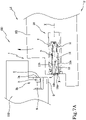
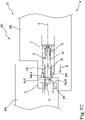
- FIGS 7A-7D illustrate the door or window 100 having the lock body 20 (in particular the switch 5 is shown) and the counter-plate 2 (in particular the first magnetic member 3 is shown), in some operating steps of the invention.
- Figure 7A shows the final part of the closing step of the door or window, when the door or window leaf and the fixed frame are not yet approached and the lock body 20 is therefore distal to the counter-plate 2.
- the first magnetic member 3 is held in the retracted configuration by the recall means 8, while on the lock body 20, the switch 5 (locking pin 10) does not interact with the first magnetic member 3 and maintains the closing means 4 in the retained configuration.
- the switch 5 (locking pin 10) is held in the locked position by the elastic recall element 11.
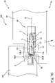
- Figure 7B shows the initial approaching step of the door or window leaf with respect to the fixed frame, in which the lock body 20 starts facing the counter-plate 2. If present, the second magnetic member 6 attracts the first magnetic member 3 (arrow A) which assumes the extracted configuration, resting on the front portion of the lock body 20, at the switch 5 (locking pin 10). In greater detail, in the case in which the support 7 is present, the first magnetic member 3, in the extracted configuration, rests thereon.
- the second leaf-side magnetic pole 14b magnetically interacts with the first leaf-side magnetic pole 3a exchanging a stabilization magnetic-type action adapted to maintain the closing means 4 in retained configuration, in particular to maintain the switch 5 (locking pin 10) in the locked position.
- This interaction is obtained thanks to the fact that the second leaf-side magnetic pole 14b is active on the closing side L2, i.e. on the side which first faces the first leaf-side magnetic pole 3a.
- the stabilization magnetic-type action is a repulsive action (arrow F1) exercised between the second leaf-side magnetic pole 14b (south pole) and the first frame-side magnetic pole 3a (south pole).
- the intensity of the magnetic fluxes is such as to ensure that the first magnetic member 3 is maintained in the extracted configuration by the action of the attraction of the second magnetic member 6 while the repulsive action exercised between the first leaf-side magnetic pole 14b (south pole) and the first frame-side magnetic pole 3a (south pole) maintains the switch 5 in the locked position (in cooperation with the elastic recall element 11). Remaining in the locked position, the switch 5 (locking pin 10) maintains the closing means 4 in the retained configuration.
- Figure 7C shows the completion of the final approaching step of the door or window leaf with respect to the fixed frame, when the leaf and the fixed frame are aligned and the lock body 20 is completely facing the counter-plate 2.
- the switch 5 and the first magnetic member 3 exchange an activation magnetic-type action adapted to activate the switching of the closing means 4 between the retained configuration and the release configuration.
- the closing means 4 comprises a hook 4a
- the latter is released and, passing through an opening 20a of the lock body 20 and the opening 2a of the counter-plate 2, hooks its hooked portion 4b to the same counter-plate.
- the switch 5 and the first magnetic member 3 exchange an activation magnetic-type action adapted to move the switch 5 between the locked position and the unlocked position (arrow B).
- the activation magnetic-type action is an attractive action (arrow F2) between the fist leaf-side magnetic pole 14a (north pole) and the first frame-side magnetic pole 3a (south pole).
- the first frame-side magnetic pole 3a extends so as to magnetically interact with the second leaf-side magnetic pole 14b at least in the initial approaching step, exchanging the stabilization magnetic-type action, and so as to magnetically interact with the first leaf-side magnetic pole 14a only in the final approaching step, exchanging the activation magnetic-type action.
- the intensity of the magnetic fluxes is such as to ensure that the activation magnetic-type action is greater than the stabilization magnetic-type action, for which the switch 5 passes from the locked position to the unlocked position, also overcoming the elastic recall element 11.
- the intensity of the magnetic fluxes is also such as to ensure that the first magnetic member 3 is maintained in the extracted configuration by the action of the attraction of the second magnetic member 6.
- the activation magnetic-type action and the stabilization magnetic-type action are opposite.
- Figure 7D shows the opening step of the door or window, when the door or window leaf and the fixed frame are partially approached and the lock body 20 is therefore still partially facing the counter-plate 2.
- the closing means 4 is recalled in the retained configuration, for example by the movement of a handle (not shown) activated by a user or by a key, or even by an electric motor.
- the first leaf-side magnetic pole 14a moves away from the first frame-side magnetic pole 3a and no longer interacts therewith.
- the second leaf-side magnetic pole 14b and the first frame-side magnetic pole 3a remain facing, magnetically interacting and exchanging a magnetic-type action, similar to the stabilization magnetic-type action, which brings the switch 5 back to the locked position (arrow C).
- the second leaf-side magnetic pole 14b (south pole) and the first frame-side magnetic pole 3a (south pole) exchange a repulsive action (arrow F1) which brings the switch 5 back in the locked position.
- the first member 3 Upon the complete distancing of the door or window leaf from the fixed frame, in the case in which the first member 3 is movable between the extracted configuration and the retracted configuration, the first member 3 is returned to the retracted configuration by the recall means 8 in so far as it is no longer subject to the magnetic interaction with the second magnetic member 6.
- the first magnetic member 3 can be rotatably movable between a retracted configuration inside the housing 2b of the counter-plate and the extracted configuration of the housing 2b, to approach the switch 5.
- This characteristic can be provided in combination with any characteristic of the previously described embodiment.
- the arrangement of the magnets, and in particular of the magnetic poles, can be different with respect to that which is described and illustrated.
- the magnetic systems concerned are arranged in such a way as to generate an activation magnetic-type action only in the final approaching step of the door or window leaf with respect to the fixed frame and possibly a stabilization magnetic-type action in the initial approaching step, thus allowing a safe and reliable switching of the switch and therefore a safe and reliable passage to the release configuration of the closing means.
- the restoration of the retracted configuration of the closing means is also safe and reliable.
Claims (12)
- Automatisches System (1) zum Schließen von Fenstern oder Türen, aufweisend:- eine Gegenplatte (2), die an einem feststehenden Rahmen anbringbar und mit einem ersten Glied (3) versehen ist;- einen Schlosskörper (20), der an einem Tür- oder Fensterflügel anbringbar ist und einen Frontabschnitt (20b) aufweist, welcher dazu vorgesehen ist, der Gegenplatte (2) gegenüberzuliegen, wenn der Tür- oder Fensterflügel mit dem feststehenden Rahmen ausgerichtet ist, wobei der Schlosskörper (20) mit einem Schließmittel (4) versehen ist, das zwischen einer Ausfahrkonfiguration, bei der das Schließmittel (4) mit der Gegenplatte (2) in Eingriff steht, wenn die Gegenplatte (2) mit dem Schlosskörper (20) ausgerichtet ist, und einer Rückhaltekonfiguration, bei der das Schließmittel (4) innerhalb des Schlosskörpers (20) gehalten wird und nicht mit der Gegenplatte (2) in Eingriff steht, bewegbar ist;- einen Schalter (5), der in dem Schlosskörper (20) angebracht ist, wobei der Schalter (5) dazu konfiguriert ist, eine Verriegelungskonfiguration, bei welcher der Schalter (5) das Schließmittel (4) in der Rückhaltekonfiguration (4) verriegelt, und eine Entriegelungskonfiguration, bei welcher der Schalter das Schließmittel (4) entriegelt und dadurch die automatische Bewegung des Schließmittels (4) von der Rückhaltekonfiguration zu der Ausfahrkonfiguration aktiviert, einzunehmen;dadurch gekennzeichnet, dassder Schalter (5) und das erste Glied (3) dazu konfiguriert sind, eine Aktivierungswirkung vom magnetischen Typ auszutauschen, die dazu ausgelegt ist, den Schalter (5) nur in einem letzten Annäherungsschritt des Schlosskörpers (20) in Bezug auf die Gegenplatte (2) von der Verriegelungskonfiguration in die Entriegelungskonfiguration umzuschalten, welcher ein Teil eines Schließschritts ist, der beginnt, wenn der Schlosskörper der Gegenplatte teilweise gegenüberliegt, und endet, wenn der Schlosskörper der Gegenplatte vollständig gegenüberliegt,wobei der Schalter (5) einen ersten flügelseitigen Magnetpol (14a) aufweist, der an dem Frontabschnitt (20b) des Schlosskörpers (20) aktiv ist, und das erste Glied (3) einen rahmenseitigen Magnetpol (3a) aufweist, der an einem Frontabschnitt (2c) der Gegenplatte (2) aktiv ist, wobei der erste flügelseitige Magnetpol (14a) nur auf einer Öffnungsseite (L1) aktiv ist, um so nur in dem letzten Annäherungsschritt mit dem ersten rahmenseitigen Magnetpol (3a) magnetisch zusammenzuwirken und die Aktivierungswirkung vom magnetischen Typ auszutauschen.
- Automatisches System (1) zum Schließen von Fenstern oder Türen nach Anspruch 1, wobei der Schalter (5) und das erste Glied (3) dazu konfiguriert sind, eine Stabilisierungswirkung vom magnetischen Typ auszutauschen, die dazu ausgelegt ist, den Schalter (5) mindestens in einem ersten Annäherungsschritt des Schlosskörpers (20) in Bezug auf die Gegenplatte (2), welcher ein Teil des Schließschritts ist und beginnt, wenn der Schlosskörper beginnt, der Gegenplatte gegenüberzuliegen, und endet, wenn der Schlosskörper der Gegenplatte teilweise gegenüberliegt, in der Verriegelungskonfiguration zu halten.
- Automatisches System (1) zum Schließen von Fenstern oder Türen nach Anspruch 2, wobei die Aktivierungswirkung vom magnetischen Typ und die Stabilisierungswirkung vom magnetischen Typ einander entgegengesetzt sind, wobei vorzugsweise die Aktivierungswirkung vom magnetischen Typ eine anziehende Wirkung ist und die Stabilisierungswirkung vom magnetischen Typ eine abstoßende Wirkung ist.
- Automatisches System (1) zum Schließen von Fenstern oder Türen nach Anspruch 2 oder 3, wobei der Schalter (5) einen zweiten flügelseitigen Magnetpol (14b) aufweist, der eine der Polarität des ersten flügelseitigen Magnetpols (14a) entgegengesetzte Polarität aufweist, wobei der zweite flügelseitige Magnetpol (14b) an dem Frontabschnitt (20b) des Verriegelungskörpers (20) und nur auf einer Schließseite (L2) aktiv ist.
- Automatisches System (1) zum Schließen von Fenstern oder Türen nach Anspruch 4, wobei sich der erste rahmenseitige Magnetpol (3a) so erstreckt, dass er mit dem flügelseitigen Magnetpol (14b) mindestens in dem ersten Annäherungsschritt magnetisch zusammenwirkt, wobei er die Stabilisierungswirkung vom magnetischen Typ austauscht, und so, dass er mit dem ersten flügelseitigen Magnetpol (14a) nur in dem letzten Annäherungsschritt magnetisch zusammenwirkt, wobei er die Aktivierungswirkung vom magnetischen Typ austauscht.
- Automatisches System (1) zum Schließen von Fenstern oder Türen nach Anspruch 4 oder 5, wobei der Schalter (5) einstellbar ist, um die Position des ersten flügelseitigen Magnetpols (14a) und des zweiten flügelseitigen Magnetpols (14b) auf der Ebene des Frontabschnitts (20b) des Schlosskörpers (20) umzukehren.
- Automatisches System (1) zum Schließen von Fenstern oder Türen nach einem oder mehreren der vorhergehenden Ansprüche, wobei der Schalter (5) zwischen einer Verriegelungsposition, die der Verriegelungskonfiguration entspricht, und einer Entriegelungsposition, die der Entriegelungskonfiguration entspricht, bewegbar ist und vorzugsweise durch einen Verriegelungsbolzen (10) definiert wird, der zwischen der Verriegelungsposition und der Entriegelungsposition axial verschiebbar ist.
- Automatisches System (1) zum Schließen von Fenstern oder Türen nach Anspruch 7, wobei der Verriegelungsbolzen (10), der vorzugsweise aus einem nichtmagnetischen Material hergestellt ist, einen Permanentmagnet (12) aufweist, der entlang der Längsachse (X) angeordnet ist und entgegengesetzte Pole aufweist, die auf entgegengesetzten Seiten derselben Längsachse aktiv sind, und dem Permanentmagnet (12) benachbart zwei ferromagnetische Elemente (13a, 13b) aufweist, die auf einer Schließseite (L2) bzw. einer Öffnungsseite (L1) angeordnet sind und als Effekt des Zusammenwirkens mit dem Permanentmagnet (12) einen ersten flügelseitigen Magnetpol (14a) bzw. einen zweiten flügelseitigen Magnetpol (14b) definieren.
- Automatisches System (1) zum Schließen von Fenstern oder Türen nach Anspruch 8, wobei der Verriegelungsbolzen (10) um die Längsachse (X) drehbar ist, um die Position des ersten flügelseitigen Magnetpols (14a) und des zweiten flügelseitigen Magnetpols (14b) auf der Ebene des Frontabschnitts (20b) des Schlosskörpers (20) umzukehren.
- Automatisches System (1) zum Schließen von Fenstern oder Türen nach einem oder mehreren der vorhergehenden Ansprüche, wobei das erste Glied (3) in Bezug auf die Gegenplatte (2) bewegbar ist und wobei ein zweites Glied (6), das von dem Schalter (5) abgegrenzt und getrennt ist, auf eine Weise ganzheitlich an dem Schlosskörper (20) befestigt ist, dass, wenn der Flügel mit dem feststehenden Rahmen ausgerichtet ist, das zweite Glied (6) eine Anziehungskraft von einem magnetischen Typ auf das erste Glied (3) ausübt, welche das erste Glied (3) an den Schlosskörper (20) auf eine Weise annähert, dass es mit dem Schalter (5) magnetisch zusammenwirkt, um das automatische Schalten des Schließmittels (4) von der Rückhaltekonfiguration zu der Ausfahrkonfiguration zu aktivieren.
- Automatisches System (1) zum Schließen von Fenstern oder Türen nach Anspruch 10, wobei das erste Glied (3) zwischen einer zurückgezogenen Konfiguration, bei der das erste Glied (3) innerhalb eines Gehäuses (2b) der Gegenplatte (2) zurückgezogen ist, und einer ausgefahrenen Konfiguration, bei der das erste Glied (3) aus dem Gehäuse (2b) ausgefahren ist, vorzugsweise auf verschiebbare oder drehbare Weise bewegbar ist, um sich dem Schalter (5) zu nähern, und wobei sich, wenn es sich in der ausgefahrenen Konfiguration befindet, das erste Glied (3) in einer Ruheposition, auch indirekt, an einer Kantenoberfläche, welche einen Teil des Schlosskörpers (20) darstellt, an dem Schalter (5) befindet.
- Tür oder Fenster, dadurch gekennzeichnet, dass sie/es ein automatisches Schließsystem (1) nach einem beliebigen der vorhergehenden Ansprüche aufweist.
Applications Claiming Priority (2)
| Application Number | Priority Date | Filing Date | Title |
|---|---|---|---|
| IT201900004329 | 2019-03-26 | ||
| PCT/IB2020/051916 WO2020194089A1 (en) | 2019-03-26 | 2020-03-05 | Automatic system for closing windows or doors |
Publications (2)
| Publication Number | Publication Date |
|---|---|
| EP3914792A1 EP3914792A1 (de) | 2021-12-01 |
| EP3914792B1 true EP3914792B1 (de) | 2022-06-29 |
Family
ID=67002241
Family Applications (1)
| Application Number | Title | Priority Date | Filing Date |
|---|---|---|---|
| EP20706377.7A Active EP3914792B1 (de) | 2019-03-26 | 2020-03-05 | Automatisches system zum schliessen von fenstern oder türen |
Country Status (2)
| Country | Link |
|---|---|
| EP (1) | EP3914792B1 (de) |
| WO (1) | WO2020194089A1 (de) |
Citations (10)
| Publication number | Priority date | Publication date | Assignee | Title |
|---|---|---|---|---|
| GB1009996A (en) | 1961-08-21 | 1965-11-17 | Licentia Gmbh | A magnetic fastening device |
| DE8704036U1 (de) | 1987-03-18 | 1987-07-02 | Bks Gmbh, 5620 Velbert, De | |
| US7308737B2 (en) | 2005-02-09 | 2007-12-18 | Washin Optical Co., Ltd. | Magnetically actuated locking mechanism |
| EP2096241A2 (de) | 2008-02-28 | 2009-09-02 | Carl Fuhr GmbH & Co. KG | selbstverriegelnde Zusatzverriegelung |
| DE202011103779U1 (de) | 2011-07-06 | 2012-10-15 | Maco Technologie Gmbh | Schloss |
| EP2634330A2 (de) | 2012-02-28 | 2013-09-04 | Aug. Winkhaus GmbH & Co. KG | Automatikschloss |
| DE202014009713U1 (de) | 2014-12-10 | 2015-01-30 | Kfv Karl Fliether Gmbh & Co. Kg | Magnetanordnung |
| EP2314810B1 (de) | 2009-10-26 | 2017-03-08 | KFV Karl Fliether GmbH & Co. KG | Treibstangenverschluss mit einer Treibstangensperre |
| WO2017158449A1 (en) | 2016-03-15 | 2017-09-21 | Alban Giacomo S.P.A. | Automatic system for closing windows or doors |
| DE102017105125A1 (de) | 2017-03-10 | 2018-09-13 | Carl Fuhr Gmbh & Co. Kg | Verriegelungseinheit für eine Schließanlage einer Tür |
-
2020
- 2020-03-05 EP EP20706377.7A patent/EP3914792B1/de active Active
- 2020-03-05 WO PCT/IB2020/051916 patent/WO2020194089A1/en unknown
Patent Citations (10)
| Publication number | Priority date | Publication date | Assignee | Title |
|---|---|---|---|---|
| GB1009996A (en) | 1961-08-21 | 1965-11-17 | Licentia Gmbh | A magnetic fastening device |
| DE8704036U1 (de) | 1987-03-18 | 1987-07-02 | Bks Gmbh, 5620 Velbert, De | |
| US7308737B2 (en) | 2005-02-09 | 2007-12-18 | Washin Optical Co., Ltd. | Magnetically actuated locking mechanism |
| EP2096241A2 (de) | 2008-02-28 | 2009-09-02 | Carl Fuhr GmbH & Co. KG | selbstverriegelnde Zusatzverriegelung |
| EP2314810B1 (de) | 2009-10-26 | 2017-03-08 | KFV Karl Fliether GmbH & Co. KG | Treibstangenverschluss mit einer Treibstangensperre |
| DE202011103779U1 (de) | 2011-07-06 | 2012-10-15 | Maco Technologie Gmbh | Schloss |
| EP2634330A2 (de) | 2012-02-28 | 2013-09-04 | Aug. Winkhaus GmbH & Co. KG | Automatikschloss |
| DE202014009713U1 (de) | 2014-12-10 | 2015-01-30 | Kfv Karl Fliether Gmbh & Co. Kg | Magnetanordnung |
| WO2017158449A1 (en) | 2016-03-15 | 2017-09-21 | Alban Giacomo S.P.A. | Automatic system for closing windows or doors |
| DE102017105125A1 (de) | 2017-03-10 | 2018-09-13 | Carl Fuhr Gmbh & Co. Kg | Verriegelungseinheit für eine Schließanlage einer Tür |
Also Published As
| Publication number | Publication date |
|---|---|
| EP3914792A1 (de) | 2021-12-01 |
| WO2020194089A1 (en) | 2020-10-01 |
Similar Documents
| Publication | Publication Date | Title |
|---|---|---|
| US5474342A (en) | Door latch actuator | |
| US4254582A (en) | Electrically actuated overhead garage door opener assembly | |
| US6630877B2 (en) | Electromagnetic closing and opening device for door leaves that can be pivoted | |
| CA2191266A1 (en) | Catch mechanism for locks | |
| CN114450457B (zh) | 锁定装置和系统 | |
| DE202015101504U1 (de) | Verriegelungssystem | |
| US5718135A (en) | Locks | |
| EP0231532B1 (de) | Schloss mit äusserer Bolzenfreigabevorrichtung | |
| EP3914792B1 (de) | Automatisches system zum schliessen von fenstern oder türen | |
| EP3430216B1 (de) | Automatisches system zum verschliessen von fenstern oder türen | |
| JP2014066003A (ja) | 電子錠付き扉の非常解錠装置 | |
| EP2390442B1 (de) | Schließsystem | |
| CN111183265B (zh) | 锁 | |
| RU85532U1 (ru) | Электромеханическое запирающее устройство | |
| CN111902593B (zh) | 窗或门 | |
| CN112236571B (zh) | 用于滑动门的锁、配件、撞击板和闭合装置、以及滑动门系统 | |
| KR101990693B1 (ko) | 방범 방충망용 잠금장치 | |
| GB2389141A (en) | A lockable handle assembly | |
| KR200485299Y1 (ko) | 슬라이딩 도어용 잠금장치 | |
| KR200392358Y1 (ko) | 도어록용 키홀 보호덮개 | |
| EP4141201A1 (de) | Verriegelungsvorrichtung und schloss mit klemme für eine schiebetür oder ein schiebefenster | |
| EP3918162B1 (de) | Verriegelungsvorrichtung für fenster und türen | |
| RU2114974C1 (ru) | Электромеханический замок | |
| GB2421274A (en) | Sash locking system with magnetic key release | |
| RU125238U1 (ru) | Электромеханический замок |
Legal Events
| Date | Code | Title | Description |
|---|---|---|---|
| STAA | Information on the status of an ep patent application or granted ep patent |
Free format text: STATUS: UNKNOWN |
|
| STAA | Information on the status of an ep patent application or granted ep patent |
Free format text: STATUS: THE INTERNATIONAL PUBLICATION HAS BEEN MADE |
|
| PUAI | Public reference made under article 153(3) epc to a published international application that has entered the european phase |
Free format text: ORIGINAL CODE: 0009012 |
|
| STAA | Information on the status of an ep patent application or granted ep patent |
Free format text: STATUS: REQUEST FOR EXAMINATION WAS MADE |
|
| 17P | Request for examination filed |
Effective date: 20210824 |
|
| AK | Designated contracting states |
Kind code of ref document: A1 Designated state(s): AL AT BE BG CH CY CZ DE DK EE ES FI FR GB GR HR HU IE IS IT LI LT LU LV MC MK MT NL NO PL PT RO RS SE SI SK SM TR |
|
| GRAP | Despatch of communication of intention to grant a patent |
Free format text: ORIGINAL CODE: EPIDOSNIGR1 |
|
| STAA | Information on the status of an ep patent application or granted ep patent |
Free format text: STATUS: GRANT OF PATENT IS INTENDED |
|
| INTG | Intention to grant announced |
Effective date: 20220314 |
|
| GRAS | Grant fee paid |
Free format text: ORIGINAL CODE: EPIDOSNIGR3 |
|
| GRAA | (expected) grant |
Free format text: ORIGINAL CODE: 0009210 |
|
| STAA | Information on the status of an ep patent application or granted ep patent |
Free format text: STATUS: THE PATENT HAS BEEN GRANTED |
|
| AK | Designated contracting states |
Kind code of ref document: B1 Designated state(s): AL AT BE BG CH CY CZ DE DK EE ES FI FR GB GR HR HU IE IS IT LI LT LU LV MC MK MT NL NO PL PT RO RS SE SI SK SM TR |
|
| DAV | Request for validation of the european patent (deleted) | ||
| DAX | Request for extension of the european patent (deleted) | ||
| REG | Reference to a national code |
Ref country code: CH Ref legal event code: EP |
|
| REG | Reference to a national code |
Ref country code: AT Ref legal event code: REF Ref document number: 1501464 Country of ref document: AT Kind code of ref document: T Effective date: 20220715 |
|
| REG | Reference to a national code |
Ref country code: IE Ref legal event code: FG4D |
|
| REG | Reference to a national code |
Ref country code: DE Ref legal event code: R096 Ref document number: 602020003792 Country of ref document: DE |
|
| REG | Reference to a national code |
Ref country code: LT Ref legal event code: MG9D |
|
| PG25 | Lapsed in a contracting state [announced via postgrant information from national office to epo] |
Ref country code: SE Free format text: LAPSE BECAUSE OF FAILURE TO SUBMIT A TRANSLATION OF THE DESCRIPTION OR TO PAY THE FEE WITHIN THE PRESCRIBED TIME-LIMIT Effective date: 20220629 Ref country code: NO Free format text: LAPSE BECAUSE OF FAILURE TO SUBMIT A TRANSLATION OF THE DESCRIPTION OR TO PAY THE FEE WITHIN THE PRESCRIBED TIME-LIMIT Effective date: 20220929 Ref country code: LT Free format text: LAPSE BECAUSE OF FAILURE TO SUBMIT A TRANSLATION OF THE DESCRIPTION OR TO PAY THE FEE WITHIN THE PRESCRIBED TIME-LIMIT Effective date: 20220629 Ref country code: HR Free format text: LAPSE BECAUSE OF FAILURE TO SUBMIT A TRANSLATION OF THE DESCRIPTION OR TO PAY THE FEE WITHIN THE PRESCRIBED TIME-LIMIT Effective date: 20220629 Ref country code: GR Free format text: LAPSE BECAUSE OF FAILURE TO SUBMIT A TRANSLATION OF THE DESCRIPTION OR TO PAY THE FEE WITHIN THE PRESCRIBED TIME-LIMIT Effective date: 20220930 Ref country code: FI Free format text: LAPSE BECAUSE OF FAILURE TO SUBMIT A TRANSLATION OF THE DESCRIPTION OR TO PAY THE FEE WITHIN THE PRESCRIBED TIME-LIMIT Effective date: 20220629 Ref country code: BG Free format text: LAPSE BECAUSE OF FAILURE TO SUBMIT A TRANSLATION OF THE DESCRIPTION OR TO PAY THE FEE WITHIN THE PRESCRIBED TIME-LIMIT Effective date: 20220929 |
|
| REG | Reference to a national code |
Ref country code: NL Ref legal event code: MP Effective date: 20220629 |
|
| PG25 | Lapsed in a contracting state [announced via postgrant information from national office to epo] |
Ref country code: RS Free format text: LAPSE BECAUSE OF FAILURE TO SUBMIT A TRANSLATION OF THE DESCRIPTION OR TO PAY THE FEE WITHIN THE PRESCRIBED TIME-LIMIT Effective date: 20220629 Ref country code: LV Free format text: LAPSE BECAUSE OF FAILURE TO SUBMIT A TRANSLATION OF THE DESCRIPTION OR TO PAY THE FEE WITHIN THE PRESCRIBED TIME-LIMIT Effective date: 20220629 |
|
| PG25 | Lapsed in a contracting state [announced via postgrant information from national office to epo] |
Ref country code: NL Free format text: LAPSE BECAUSE OF FAILURE TO SUBMIT A TRANSLATION OF THE DESCRIPTION OR TO PAY THE FEE WITHIN THE PRESCRIBED TIME-LIMIT Effective date: 20220629 |
|
| PG25 | Lapsed in a contracting state [announced via postgrant information from national office to epo] |
Ref country code: SM Free format text: LAPSE BECAUSE OF FAILURE TO SUBMIT A TRANSLATION OF THE DESCRIPTION OR TO PAY THE FEE WITHIN THE PRESCRIBED TIME-LIMIT Effective date: 20220629 Ref country code: SK Free format text: LAPSE BECAUSE OF FAILURE TO SUBMIT A TRANSLATION OF THE DESCRIPTION OR TO PAY THE FEE WITHIN THE PRESCRIBED TIME-LIMIT Effective date: 20220629 Ref country code: RO Free format text: LAPSE BECAUSE OF FAILURE TO SUBMIT A TRANSLATION OF THE DESCRIPTION OR TO PAY THE FEE WITHIN THE PRESCRIBED TIME-LIMIT Effective date: 20220629 Ref country code: PT Free format text: LAPSE BECAUSE OF FAILURE TO SUBMIT A TRANSLATION OF THE DESCRIPTION OR TO PAY THE FEE WITHIN THE PRESCRIBED TIME-LIMIT Effective date: 20221031 Ref country code: ES Free format text: LAPSE BECAUSE OF FAILURE TO SUBMIT A TRANSLATION OF THE DESCRIPTION OR TO PAY THE FEE WITHIN THE PRESCRIBED TIME-LIMIT Effective date: 20220629 Ref country code: EE Free format text: LAPSE BECAUSE OF FAILURE TO SUBMIT A TRANSLATION OF THE DESCRIPTION OR TO PAY THE FEE WITHIN THE PRESCRIBED TIME-LIMIT Effective date: 20220629 |
|
| PG25 | Lapsed in a contracting state [announced via postgrant information from national office to epo] |
Ref country code: PL Free format text: LAPSE BECAUSE OF FAILURE TO SUBMIT A TRANSLATION OF THE DESCRIPTION OR TO PAY THE FEE WITHIN THE PRESCRIBED TIME-LIMIT Effective date: 20220629 Ref country code: IS Free format text: LAPSE BECAUSE OF FAILURE TO SUBMIT A TRANSLATION OF THE DESCRIPTION OR TO PAY THE FEE WITHIN THE PRESCRIBED TIME-LIMIT Effective date: 20221029 |
|
| REG | Reference to a national code |
Ref country code: DE Ref legal event code: R026 Ref document number: 602020003792 Country of ref document: DE |
|
| PLBI | Opposition filed |
Free format text: ORIGINAL CODE: 0009260 |
|
| PG25 | Lapsed in a contracting state [announced via postgrant information from national office to epo] |
Ref country code: AL Free format text: LAPSE BECAUSE OF FAILURE TO SUBMIT A TRANSLATION OF THE DESCRIPTION OR TO PAY THE FEE WITHIN THE PRESCRIBED TIME-LIMIT Effective date: 20220629 |
|
| 26 | Opposition filed |
Opponent name: KFV KARL FLIETHER GMBH & CO. KG Effective date: 20230314 |
|
| PG25 | Lapsed in a contracting state [announced via postgrant information from national office to epo] |
Ref country code: DK Free format text: LAPSE BECAUSE OF FAILURE TO SUBMIT A TRANSLATION OF THE DESCRIPTION OR TO PAY THE FEE WITHIN THE PRESCRIBED TIME-LIMIT Effective date: 20220629 Ref country code: CZ Free format text: LAPSE BECAUSE OF FAILURE TO SUBMIT A TRANSLATION OF THE DESCRIPTION OR TO PAY THE FEE WITHIN THE PRESCRIBED TIME-LIMIT Effective date: 20220629 |
|
| PGFP | Annual fee paid to national office [announced via postgrant information from national office to epo] |
Ref country code: DE Payment date: 20230328 Year of fee payment: 4 Ref country code: BE Payment date: 20230323 Year of fee payment: 4 |
|
| PLAX | Notice of opposition and request to file observation + time limit sent |
Free format text: ORIGINAL CODE: EPIDOSNOBS2 |
|
| P01 | Opt-out of the competence of the unified patent court (upc) registered |
Effective date: 20230523 |
|
| PLBB | Reply of patent proprietor to notice(s) of opposition received |
Free format text: ORIGINAL CODE: EPIDOSNOBS3 |
|
| PG25 | Lapsed in a contracting state [announced via postgrant information from national office to epo] |
Ref country code: MC Free format text: LAPSE BECAUSE OF FAILURE TO SUBMIT A TRANSLATION OF THE DESCRIPTION OR TO PAY THE FEE WITHIN THE PRESCRIBED TIME-LIMIT Effective date: 20220629 |
|
| REG | Reference to a national code |
Ref country code: CH Ref legal event code: PL |
|
| REG | Reference to a national code |
Ref country code: AT Ref legal event code: UEP Ref document number: 1501464 Country of ref document: AT Kind code of ref document: T Effective date: 20220629 |
|
| PG25 | Lapsed in a contracting state [announced via postgrant information from national office to epo] |
Ref country code: LU Free format text: LAPSE BECAUSE OF NON-PAYMENT OF DUE FEES Effective date: 20230305 |
|
| REG | Reference to a national code |
Ref country code: IE Ref legal event code: MM4A |
|
| PG25 | Lapsed in a contracting state [announced via postgrant information from national office to epo] |
Ref country code: LI Free format text: LAPSE BECAUSE OF NON-PAYMENT OF DUE FEES Effective date: 20230331 Ref country code: IT Free format text: LAPSE BECAUSE OF FAILURE TO SUBMIT A TRANSLATION OF THE DESCRIPTION OR TO PAY THE FEE WITHIN THE PRESCRIBED TIME-LIMIT Effective date: 20220629 Ref country code: IE Free format text: LAPSE BECAUSE OF NON-PAYMENT OF DUE FEES Effective date: 20230305 Ref country code: FR Free format text: LAPSE BECAUSE OF NON-PAYMENT OF DUE FEES Effective date: 20230331 Ref country code: CH Free format text: LAPSE BECAUSE OF NON-PAYMENT OF DUE FEES Effective date: 20230331 |