EP2634063B1 - Schiebetür eines Schienenfahrzeugs - Google Patents
Schiebetür eines Schienenfahrzeugs Download PDFInfo
- Publication number
- EP2634063B1 EP2634063B1 EP13152980.2A EP13152980A EP2634063B1 EP 2634063 B1 EP2634063 B1 EP 2634063B1 EP 13152980 A EP13152980 A EP 13152980A EP 2634063 B1 EP2634063 B1 EP 2634063B1
- Authority
- EP
- European Patent Office
- Prior art keywords
- rails
- door
- rail
- rail vehicle
- sliding door
- Prior art date
- Legal status (The legal status is an assumption and is not a legal conclusion. Google has not performed a legal analysis and makes no representation as to the accuracy of the status listed.)
- Active
Links
- 238000011161 development Methods 0.000 description 6
- 230000018109 developmental process Effects 0.000 description 6
- 230000033001 locomotion Effects 0.000 description 6
- 238000005096 rolling process Methods 0.000 description 2
- 230000001419 dependent effect Effects 0.000 description 1
- 238000009434 installation Methods 0.000 description 1
- 238000000926 separation method Methods 0.000 description 1
Images

Classifications
-
- B—PERFORMING OPERATIONS; TRANSPORTING
- B61—RAILWAYS
- B61D—BODY DETAILS OR KINDS OF RAILWAY VEHICLES
- B61D19/00—Door arrangements specially adapted for rail vehicles
- B61D19/003—Door arrangements specially adapted for rail vehicles characterised by the movements of the door
- B61D19/005—Door arrangements specially adapted for rail vehicles characterised by the movements of the door sliding
Definitions
- the invention relates to a sliding door for a rail vehicle, with two door wings, which are guided parallel to each other, each in a rail.
- Such sliding doors are well known in the art, for example from the FR 1 538 454 A , Since the door leaves are guided parallel to each other in the rails, the rails are arranged to extend parallel to each other. In a simple way, they are formed by grooves which lie in a plane and are arranged side by side. This requires a given space for the rails.
- the publication FR 2 333 926 A discloses a shower cubicle with door leaves offset parallel to one another, wherein the door leaves are arranged suspended in the rails.
- the object of the invention is to reduce the depth of the sliding door.
- a sliding door according to the invention for a rail vehicle therefore comprises at least two door wings, which are axially guided in each case in a rail.
- the direction in which the sliding door can be opened and closed, and thus the directions in which the door leaves can be moved, are determined by the longitudinal axes of the respective rails.
- the rails are arranged in particular substantially parallel to each other. Thus, the door leaves are parallel to each other.
- the rails of a sliding door according to the invention are arranged so that they are offset in a first direction from one another and that they overlap one another in a second direction.
- the first direction stands perpendicular to the longitudinal axes of the rails and perpendicular to the normals of the door, so parallel to the door itself.
- the second direction is indicated by the normals on the door wings.
- the rails are attached to a ceiling of the rail vehicle.
- the door leaves are arranged according hanging in the rails.
- the sliding door is provided in an interior of the rail vehicle between two interior parts, in particular for the separation of two interior parts, in particular in the hallway.
- the rails are configured according to a development of the sliding door according to the invention as roller guides, in particular as at least one side undercut grooves in which rollers are mounted, by means of which the door wings are slidably mounted in rails.
- the sliding door comprises rolling elements, by means of which the door wings are displaceably mounted in rails, which in turn are designed as Wälz stressesmaschinefige, so-called cage guides.
- Other options include, for example, wave guides, with shafts as rails or profiled rail guides.
- the sliding door comprises means for power-operated to move the door along the rails.
- the door leaves are in particular connected to each other so that predetermined movements of a door leaf on the other door leaves are transferable, for example via a driver's sword or attached to the door stops.
- a force acting on a door leaf parallel to the rails thus sets this door along the rails in motion, and leads in a predetermined manner to the movement of the other door leaves.
- the force can be introduced for example via a door handle with which the door is fogged.
- a sliding door comprises means for opening and closing the sliding door, for example a linear drive with a motor, for example an electric motor and a corresponding gear, in particular a linear gear, for example with a rack or a threaded spindle.
- the sliding door can alternatively also be opened and closed pneumatically or hydraulically.
- the rails may also have axial stops, for example, in that they have different lengths in order to limit the movements of the door wings along the rails.
- the sliding door comprises at least three door leaves, which are each guided in a rail, wherein the rails are arranged in a staircase shape to each other.
- a further development of the sliding door according to the invention is characterized in that the sliding door comprises at least three door leaves, which are each guided in a rail, wherein the rails are arranged pyramid-shaped to each other.
- two rails are arranged in a plane which is arranged in a direction perpendicular to the longitudinal axes of the rails and perpendicular to the normals on the door leaves offset from a third rail.
- the two rails in one plane do not overlap.
- the third rail overlaps the two rails in the plane respectively in the direction of the normal on the door wings.
- An inventive rail vehicle has a sliding door according to the invention.
- a sliding door according to the invention is shown in cross section. It comprises three door leaves 1, 2 and 3, which are guided parallel to each other in each case a rail 4, 5 and 6.
- a first door leaf 1 is guided in a first rail 4
- a second door leaf 2 is guided in a second rail 5
- a third door leaf 3 is guided in a third rail 6.
- the rails 4, 5 and 6 are parallel to each other.
- the rails 4, 5 and 6 are offset from one another.
- the horizontal direction ie perpendicular to the door wings 1, 2 and 3, the rails 4, 5 and 6 overlap.
- the illustrated embodiment is stepped.
- the first rail 4 and the second rail 5 overlap each other and the second rail 5 and the third rail 6 overlap each other when the rails 4, 5 and 6 are projected into a horizontal plane.
- the rails 4, 5 and 6 are the same here. They each form a guide for rollers 7. These are so-called roller guides. Alternatively, of course, other types of rails, such as e.g. Cage rails or rails, equally usable.
- rollers 7 are mounted, which in turn are connected to the door wings 1, 2 and 3.
- the door wings 1, 2 and 3 axes perpendicular to the door leaves 1, 2 and 3, about which the rollers 7 are rotatably mounted.
- the rails 4, 5 and 6 enclose the rollers 7, here on all four sides perpendicular to the longitudinal axes of the rails 4, 5 and 6.
- rollers 7, 5 and 6 have in this embodiment, in each case on one side undercut groove, which form the channel for the rollers 7. These wallow themselves here at the undercut itself.
- rollers 7, other rolling elements or sliding guides are used.
- the sliding door is arranged on a ceiling 9 of a rail vehicle, whereby the door leaves 1, 2 and 3 hang down from the ceiling 9 in the vertical direction. Not sketched are the drive of the door wings 1, 2 and 3 and their mechanical connections with each other.
- the rails 4, 5 and 6 are formed in this case from a block 10.
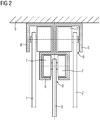
- the sliding door in Fig. 2 is different from the sliding door Fig. 1 in particular in that the rails 4, 5 and 6 are arranged pyramid-shaped instead of stepped.
- the first rail 4 is offset from the third rail 6 in a direction parallel to the door leaves 1, 2 and 3.
- the second rail 5 is arranged offset to the third rail 6.
- the first and second rails 4 and 5, however, are in a common plane, perpendicular to the door wings 1, 2 and 3, which are also stored hanging here from the ceiling 9 in the vertical direction.
- first and second rails 4 and 5 overlap the third rail 6.
- the first and second rails 4 and 5 do not overlap each other.
- the third rail 6 is designed according to the embodiment as an undercut groove.
- the third door 3 has an axis about which two rollers 7 are rotatably mounted.
- the rollers 7 are located on different sides of the third door 3. From the slot opening 8, the third door 3 is led out of the third rail 6.
- the rollers 7 roll each on one of the two undercuts.
- the groove edges form, as in the other embodiments, stops for the rollers 7 perpendicular to the direction of movement of the door.
- the groove bottom is not touched by the rollers 7 as a rule. However, it forms another stop perpendicular to the direction of movement.
- the rollers 7 are enclosed on three sides.
- the sliding door is provided in particular in an interior of the rail vehicle between two interior parts.
Landscapes
- Engineering & Computer Science (AREA)
- Mechanical Engineering (AREA)
- Support Devices For Sliding Doors (AREA)
- Gates (AREA)
Description
- Die Erfindung betrifft eine Schiebetür für ein Schienenfahrzeug, mit zwei Türflügeln, welche parallel zueinander, jeweils in einer Schiene geführt sind.
- Derartige Schiebetüren sind dem Fachmann durchaus bekannt, beispielsweise aus der
FR 1 538 454 A - Die Druckschrift
FR 2 333 926 A - Die Aufgabe der Erfindung besteht darin, die Tiefe der Schiebetür zu verringern.
- Gelöst wird die Aufgabe durch den Gegenstand des unabhängigen Patentanspruchs 1. Weiterbildungen der Erfindung finden sich in den Merkmalen der abhängigen Patentansprüchen wieder.
- Eine erfindungsgemäße Schiebetür für ein Schienenfahrzeug umfasst daher zumindest zwei Türflügel, welche jeweils in einer Schiene axial geführt sind. Die Richtung, in welche sich die Schiebetür öffnen und schließen lässt und damit die Richtungen in welche sich die Türflügel bewegen lassen, werden durch die Längsachsen der jeweiligen Schienen vorgegeben. Die Schienen sind dabei insbesondere im Wesentlichen parallel zueinander verlaufend angeordnet. Damit sind auch die Türflügel parallel zueinander.
- Des Weiteren sind die Schienen einer erfindungsgemäßen Schiebetür erfindungsgemäß so angeordnet, dass sie in einer ersten Richtung versetzt zueinander verlaufen und, dass sie in einer zweiten Richtung einander überlappen. Die erste Richtung steht dabei senkrecht auf den Längsachsen der Schienen und senkrecht auf den Normalen der Türflügel, also parallel zu den Türflügeln selbst. Die zweite Richtung wird von den Normalen auf den Türflügeln angezeigt.
- Die Projektionen der Schienen in eine zu den Schienen parallel verlaufende Ebene, welche die Türflügel senkrecht schneidet, überlappen sich somit. Die Tiefe der Schiebetür, senkrecht zu den Türflügeln, ist daher verringert.
- Die Schienen sind an einer Decke des Schienenfahrzeugs befestigt. Die Türflügel sind entsprechend in den Schienen hängend angeordnet.
- Darüber hinaus ist die Schiebetür in einem Innenraum des Schienenfahrzeugs zwischen zwei Innenraumteilen vorgesehen, insbesondere zur Abtrennung von zwei Innenraumteilen, insbesondere im Gang.
- Die Schienen sind gemäß einer Weiterbildung der erfindungsgemäßen Schiebetür als Laufrollenführungen, insbesondere als zumindest einseitig hinterschnittene Nuten ausgestaltet, in welchen Laufrollen gelagert sind, mittels welcher die Türflügel in Schienen verschiebbar gelagert sind.
- Gemäß einer alternativen Weiterbildung der erfindungsgemäßen Lösung umfasst die Schiebetür Wälzkörper, mittels welcher die Türflügel in Schienen verschiebbar gelagert sind, welche ihrerseits als Wälzkörperkäfige ausgestaltet sind, so genannte Käfigführungen. Weitere Möglichkeiten bilden beispielsweise Wellenführungen, mit Wellen als Schienen oder Profilschienenführungen.
- In einer weiteren Weiterbildung der Erfindung ist vorgesehen, dass die Schiebetür Mittel umfasst, um die Türflügel kraftbetätigt entlang der Schienen zu verschieben. Die Türflügel sind insbesondere untereinander so verbunden, dass vorgegebene Bewegungen eines Türflügels auf die anderen Türflügel übertragbar sind, beispielsweise über ein Mitnehmerschwert oder an den Türflügeln angebrachte Anschläge. Eine an einem Türflügel angreifende Kraft parallel zu den Schienen, setzt somit diesen Türflügel entlang der Schienen in Bewegung, und führt in vorgegebener Weise zur Bewegung auch der anderen Türflügel. Die Kraft kann beispielsweise über einen Türgriff eingeleitet werden, mit welchem der Türflügel beschlagen ist. Ist eine Schiebetür kraftbetätigt umfasst sie Mittel zum Öffnen und Schließen der Schiebetür, beispielsweise einen Linearantrieb mit einem Motor, beispielsweise einem Elektromotor und einem entsprechendem Getriebe, insbesondere einem Lineargetriebe, z.B. mit einer Zahnstange oder einer Gewindespindel. Die Schiebetür lässt sich alternativ auch pneumatisch oder hydraulisch Öffnen und Schließen. Auch die Schienen können axiale Anschläge aufweisen, beispielsweise dadurch, dass sie unterschiedlich lang sind, um die Bewegungen der Türflügel entlang der Schienen zu begrenzen.
- Eine weitere Weiterbildung der Erfindung ist darin zu sehen, dass die Schiebetür zumindest drei Türflügel umfasst, welche jeweils in einer Schiene geführt sind, wobei die Schienen treppenförmig zueinander angeordnet sind.
- Eine weitere Weiterbildung der erfindungsgemäßen Schiebetür ist dadurch gekennzeichnet, dass die Schiebetür zumindest drei Türflügel umfasst, welche jeweils in einer Schiene geführt sind, wobei die Schienen pyramidenförmig zueinander angeordnet sind.
- Weitergebildet sind entsprechend zwei Schienen in einer Ebene angeordnet, welche in einer Richtung senkrecht zu den Längsachsen der Schienen und senkrecht zu den Normalen auf den Türflügeln versetzt zu einer dritten Schiene angeordnet ist. Die zwei Schienen in einer Ebene überlappen sich dabei nicht. Die dritte Schiene überlappt die zwei Schienen in der Ebene jeweils in Richtung der Normalen auf den Türflügeln.
- Ein erfindungsgemäßes Schienenfahrzeug weist eine erfindungsgemäße Schiebetür auf.
- Die Erfindung lässt zahlreiche Ausführungsformen zu. Sie wird anhand der nachfolgenden Figuren näher erläutert, in denen jeweils ein Ausgestaltungsbeispiel dargestellt ist. Gleiche Elemente in den Figuren sind mit gleichen Bezugszeichen versehen.
-
Fig. 1 zeigt eine erfindungsgemäße Schiebetür gemäß einer ersten Ausgestaltung schematisch in einem Querschnitt, -
Fig. 2 zeigt eine erfindungsgemäße Schiebetür gemäß einer zweiten Ausgestaltung schematisch in einem Querschnitt. - In
Fig. 1 ist eine erfindungsgemäße Schiebetür im Querschnitt dargestellt. Sie umfasst drei Türflügel 1, 2 und 3, welche parallel zueinander in jeweils einer Schiene 4, 5 und 6 geführt sind. Ein erster Türflügel 1 ist in einer ersten Schiene 4 geführt, ein zweiter Türflügel 2 ist in einer zweiten Schiene 5 geführt, und ein dritter Türflügel 3 ist in einer dritten Schiene 6 geführt. Die Schienen 4, 5 und 6 verlaufen parallel zueinander. In vertikaler Richtung, also in einer Richtung parallel zu den Türflügeln 1, 2 und 3 und senkrecht zu den Längsachsen der Schienen 4, 5 und 6, welche in die Zeichenebene hinein zeigen, sind die Schienen 4, 5 und 6 zueinander versetzt. In horizontaler Richtung, also senkrecht zu den Türflügeln 1, 2 und 3, überlappen sich die Schienen 4, 5 und 6. Dadurch wird der Bauraum in horizontaler Richtung verkleinert im Vergleich zu einer parallelen Anordnung der Schienen in einer gemeinsamen Ebene. Die veranschaulichte Ausgestaltungsform ist dabei treppenförmig. Die erste Schiene 4 und die zweite Schiene 5 überlappen einander und die zweite Schiene 5 und die dritte Schiene 6 überlappen einander, bei einer Projektion der Schienen 4, 5 und 6 in eine horizontale Ebene. - Die Schienen 4, 5 und 6 sind hier gleich ausgestaltet. Sie bilden jeweils eine Führung für Laufrollen 7. Damit handelt es sich um so genannte Laufrollenführungen. Alternativ sind selbstverständlich andere Arten von Schienen, wie z.B. Käfigschienen oder Profilschienen, gleichermaßen einsetzbar. In den Schienen 4, 5 und 6 sind Laufrollen 7 gelagert, welche ihrerseits mit den Türflügeln 1, 2 und 3 verbunden sind. Hier weisen die Türflügel 1, 2 und 3 Achsen senkrecht auf den Türflügeln 1, 2 und 3 auf, um welche die Laufrollen 7 drehbar gelagert sind. Die Schienen 4, 5 und 6 umschließen die Laufrollen 7, hier auf allen vier Seiten senkrecht zu den Längsachsen der Schienen 4, 5 und 6. Sie bilden jeweils einen Kanal, in welchem sich die Laufrollen 7 abwälzen, wobei durch eine Öffnung 8 die Türen aus der jeweiligen Schiene 4, 5 und 6 herausgeführt sind. Die Schienen 4, 5 und 6 weisen in diesem Ausführungsbeispiel jeweils eine einseitig hinterschnittene Nut auf, welche den Kanal für die Laufrollen 7 bilden. Diese wälzen sich hier am Hinterschnitt selbst ab. Statt den Laufrollen 7 sind auch andere Wälzkörper oder Gleitführungen verwendbar.
- Die Schiebetür ist an einer Decke 9 eines Schienenfahrzeugs angeordnet, wodurch die Türflügel 1, 2 und 3 von der Decke 9 in vertikaler Richtung herabhängen. Nicht skizziert sind der Antrieb der Türflügel 1, 2 und 3 und deren mechanische Verbindungen untereinander. Die Schienen 4, 5 und 6 sind in hier aus einem Block 10 ausgeformt.
- Die Schiebetür in
Fig. 2 unterscheidet sich von der Schiebetür ausFig. 1 insbesondere dadurch, dass die Schienen 4, 5 und 6 pyramidenförmig statt treppenförmig angeordnet sind. Die erste Schiene 4 ist zur dritten Schiene 6 in einer Richtung parallel zu den Türflügeln 1, 2 und 3 versetzt angeordnet. Auch die zweite Schiene 5 ist zur dritten Schiene 6 versetzt angeordnet. Die erste und zweite Schiene 4 und 5 liegen hingegen in einer gemeinsamen Ebene, senkrecht zu den Türflügeln 1, 2 und 3, welche auch hier in vertikaler Richtung von der Decke 9 hängend gelagert sind. - Bei der Projektion der Schienen 4, 5 und 6 in eine horizontale Ebene überlappen die erste und die zweite Schiene 4 und 5 die dritte Schiene 6. Die erste und zweite Schiene 4 und 5 überlappen einander nicht. Diese sind spiegelbildlich zueinander ausgestaltet, mit ähnlicher Querschnittsform wie die Schienen aus
Fig. 1 . - Die dritte Schiene 6 ist ausführungsgemäß als hinterschnittene Nut ausgeformt. Hier als doppelseitig hinterschnittene Nut. Der dritte Türflügel 3 weist eine Achse auf, um welche zwei Laufrollen 7 drehbar gelagert sind. Die Laufrollen 7 befinden sich dabei auf unterschiedlichen Seiten des dritten Türflügels 3. Aus der Nutöffnung 8 ist der dritte Türflügel 3 aus der dritten Schiene 6 herausgeführt. Die Laufrollen 7 wälzen sich jeweils auf einem der beiden Hinterschnitte ab. Die Nutflanken bilden, wie auch bei den anderen Ausführungsbeispielen, Anschläge für die Laufrollen 7 senkrecht zur Bewegungsrichtung der Türflügel. Der Nutgrund wird im Regelfall nicht von den Laufrollen 7 berührt. Er bildet jedoch einen weiteren Anschlag senkrecht zur Bewegungsrichtung. So sind auch in diesem Beispiel die Laufrollen 7 dreiseitig umschlossen.
- Die Schiebetür wird insbesondere in einem Innenraum des Schienenfahrzeugs zwischen zwei Innenraumteilen vorgesehen.
Claims (7)
- Schienenfahrzeug mit einer Schiebetür, welche zumindest zwei Türflügel (1, 2, 3) umfasst, welche parallel zueinander, jeweils in einer Schiene (4, 5, 6) geführt sind, dadurch gekennzeichnet, dass die Schienen (4, 5, 6) zueinander, in einer Richtung parallel zu den Türflügeln (1, 2, 3) versetzt sind, wobei die Schienen (4, 5, 6) einander senkrecht zu den Türflügeln (1, 2, 3) überlappend angeordnet sind, wobei die Schienen (4, 5, 6) an einer Decke (9) des Schienenfahrzeugs befestigt sind, wobei die Türflügel (1, 2, 3) in den Schienen (4, 5, 6) hängend angeordnet sind und wobei die Schiebetür in einem Innenraum des Schienenfahrzeugs zwischen zwei Innenraumteilen vorgesehen ist.
- Schienenfahrzeug nach Anspruch 1, dadurch gekennzeichnet, dass die Schienen (4, 5, 6) als Laufrollenführungen ausgestaltet sind, wobei die Schiebetür Laufrollen (7) umfasst, mittels welcher die Türflügel (1, 2, 3) in den Schienen (4, 5, 6) verschiebbar gelagert sind.
- Schienenfahrzeug nach einem der Ansprüche 1 oder 2, dadurch gekennzeichnet, dass die Schiebetür Mittel umfasst, um die Türflügel (1, 2, 3) kraftbetätigt zu verschieben.
- Schienenfahrzeug nach Anspruch 3, dadurch gekennzeichnet, dass die Mittel zumindest einen Linearantrieb umfassen.
- Schienenfahrzeug nach einem der Ansprüche 1 bis 4, dadurch gekennzeichnet, dass die Schiebetür zumindest drei Türflügel (1, 2, 3) umfasst, welche jeweils in einer Schiene (4, 5, 6) geführt sind, wobei die Schienen (4, 5, 6) treppenförmig zueinander angeordnet sind.
- Schienenfahrzeug nach einem der Ansprüche 1 bis 4, dadurch gekennzeichnet, dass die Schiebetür zumindest drei Türflügel (1, 2, 3) umfasst, welche jeweils in einer Schiene (4, 5, 6) geführt sind, wobei die Schienen (4, 5, 6) pyramidenförmig zueinander angeordnet sind.
- Schienenfahrzeug nach Anspruch 6, dadurch gekennzeichnet, dass zwei Schienen (5, 6) in einer Ebene, versetzt zur weiteren Schiene (4) angeordnet sind, welche sie jeweils senkrecht zu den Türflügeln (1, 2, 3) überlappen.
Priority Applications (1)
| Application Number | Priority Date | Filing Date | Title |
|---|---|---|---|
| PL13152980T PL2634063T3 (pl) | 2012-03-01 | 2013-01-29 | Drzwi przesuwne pojazdu szynowego |
Applications Claiming Priority (1)
| Application Number | Priority Date | Filing Date | Title |
|---|---|---|---|
| DE102012203200A DE102012203200A1 (de) | 2012-03-01 | 2012-03-01 | Schiebetür eines Schienenfahrzeugs |
Publications (2)
| Publication Number | Publication Date |
|---|---|
| EP2634063A1 EP2634063A1 (de) | 2013-09-04 |
| EP2634063B1 true EP2634063B1 (de) | 2017-12-13 |
Family
ID=47683557
Family Applications (1)
| Application Number | Title | Priority Date | Filing Date |
|---|---|---|---|
| EP13152980.2A Active EP2634063B1 (de) | 2012-03-01 | 2013-01-29 | Schiebetür eines Schienenfahrzeugs |
Country Status (7)
| Country | Link |
|---|---|
| EP (1) | EP2634063B1 (de) |
| DE (1) | DE102012203200A1 (de) |
| DK (1) | DK2634063T3 (de) |
| ES (1) | ES2662366T3 (de) |
| PL (1) | PL2634063T3 (de) |
| PT (1) | PT2634063T (de) |
| TR (1) | TR201802081T4 (de) |
Families Citing this family (2)
| Publication number | Priority date | Publication date | Assignee | Title |
|---|---|---|---|---|
| EP3798083A1 (de) | 2019-09-24 | 2021-03-31 | Bombardier Transportation GmbH | Personentransportmittel für verbesserten passagierfluss und reduzierte verweilzeiten und verfahren zur steuerung von türen |
| EP4126626B1 (de) | 2020-05-28 | 2024-04-03 | Siemens Mobility GmbH | Doppelflügelige türvorrichtung für ein fahrzeug |
Family Cites Families (7)
| Publication number | Priority date | Publication date | Assignee | Title |
|---|---|---|---|---|
| FR1538454A (fr) * | 1967-07-21 | 1968-09-06 | Venissieux Atel | Perfectionnements aux véhicules et en particulier aux wagons à portes coulissantes |
| FR2096901B1 (de) * | 1970-07-15 | 1976-05-28 | Bode & Co Geb | |
| US4090265A (en) * | 1975-12-02 | 1978-05-23 | Heinz Georg Baus | Partition wall for wet chambers |
| DE7634866U1 (de) * | 1976-11-03 | 1977-03-10 | Kermi Behaelter- U. Apparatebau, Kurt Kerschl, 8351 Pankofen | Schiebetuer fuer duschkabinen oder badewannen |
| AT795U1 (de) * | 1995-05-24 | 1996-05-28 | Richard Heinze Ges M B H & Co | Führungsanordnung für das untere ende eines plattenartigen abschlussorgans, z.b. einer schiebetür, einer trennwandung od.dgl. |
| JPH09184360A (ja) * | 1995-12-28 | 1997-07-15 | Tsuchikawa Zenji | 三連式引き戸装置 |
| AT505101A3 (de) * | 2007-04-05 | 2017-08-15 | Siemens Ag Oesterreich | Türführung und türbefestigungssystem für passagier-schienen-fahrzeuge |
-
2012
- 2012-03-01 DE DE102012203200A patent/DE102012203200A1/de not_active Withdrawn
-
2013
- 2013-01-29 DK DK13152980.2T patent/DK2634063T3/en active
- 2013-01-29 TR TR2018/02081T patent/TR201802081T4/tr unknown
- 2013-01-29 PL PL13152980T patent/PL2634063T3/pl unknown
- 2013-01-29 EP EP13152980.2A patent/EP2634063B1/de active Active
- 2013-01-29 PT PT131529802T patent/PT2634063T/pt unknown
- 2013-01-29 ES ES13152980.2T patent/ES2662366T3/es active Active
Non-Patent Citations (1)
| Title |
|---|
| None * |
Also Published As
| Publication number | Publication date |
|---|---|
| TR201802081T4 (tr) | 2018-03-21 |
| DK2634063T3 (en) | 2018-02-26 |
| PL2634063T3 (pl) | 2018-05-30 |
| DE102012203200A1 (de) | 2013-09-05 |
| PT2634063T (pt) | 2018-01-19 |
| EP2634063A1 (de) | 2013-09-04 |
| ES2662366T3 (es) | 2018-04-06 |
Similar Documents
| Publication | Publication Date | Title |
|---|---|---|
| AT519903B1 (de) | Schiene zur Führung eines Schlittens einer Möbeltüre | |
| EP3088646A1 (de) | Führungsvorrichtung für eine schiebetür | |
| EP2287428B9 (de) | Türflügelantriebsvorrichtung mit teleskopierendem Türflügel | |
| EP2992156B1 (de) | Führungsanordnung einer schiebetür, schiebetür und möbel | |
| EP2634063B1 (de) | Schiebetür eines Schienenfahrzeugs | |
| AT503874B1 (de) | Türkonstruktion für einen aufzug | |
| EP0930413A1 (de) | Seilumlenkung für seilbetätige Fensterheber | |
| EP1707726A2 (de) | Vorrichtung zum Öffnen und Schliessen eines an einem Rahmen verschiebbar angeordnetem Fenster oder Türflügels | |
| EP2794453B1 (de) | Kabinentür-schachttür-kupplung | |
| EP2540616A2 (de) | Schließmechanismus für eine mit Kraftunterstützung schließende Schiebetüre | |
| DE202012104162U1 (de) | Tür mit integriertem Linearantrieb | |
| DE102005057227B4 (de) | Vorrichtung zur Erzeugung einer Linearbewegung | |
| WO2019122069A1 (de) | Aufzugsanlage | |
| EP2014854A2 (de) | Türantrieb für mindestens einen Türflügel in einem Fahrzeug | |
| DE102014004076B4 (de) | Spritzgussmaschine mit Sicherheitstür | |
| WO2017202524A1 (de) | Beschattungsvorrichtung für eine fahrzeugscheibe | |
| EP3228791B1 (de) | Schiebetor | |
| EP4095010A1 (de) | Vorrichtung zum verschliessen von öffnungen | |
| EP3771795A1 (de) | Türanordnung mit einer stelleinheit | |
| DE102008004996A1 (de) | Fahrzeugtür mit einem durch einen Motor betätigten Fensterheber | |
| WO2005019579A1 (de) | Antriebssystem zur betätigung von klappbaren gebäudeverschlüssen | |
| DE19952250A1 (de) | Automatische Bogenschiebetüranlage | |
| DE102011013935B4 (de) | Türanordnung | |
| WO2015185716A1 (de) | Verkleidungsanordnung für eine maschinenverkleidung | |
| DE102014017406A1 (de) | Fahrkorbtür |
Legal Events
| Date | Code | Title | Description |
|---|---|---|---|
| PUAI | Public reference made under article 153(3) epc to a published international application that has entered the european phase |
Free format text: ORIGINAL CODE: 0009012 |
|
| AK | Designated contracting states |
Kind code of ref document: A1 Designated state(s): AL AT BE BG CH CY CZ DE DK EE ES FI FR GB GR HR HU IE IS IT LI LT LU LV MC MK MT NL NO PL PT RO RS SE SI SK SM TR |
|
| AX | Request for extension of the european patent |
Extension state: BA ME |
|
| 17P | Request for examination filed |
Effective date: 20140303 |
|
| RBV | Designated contracting states (corrected) |
Designated state(s): AL AT BE BG CH CY CZ DE DK EE ES FI FR GB GR HR HU IE IS IT LI LT LU LV MC MK MT NL NO PL PT RO RS SE SI SK SM TR |
|
| 17Q | First examination report despatched |
Effective date: 20170215 |
|
| GRAP | Despatch of communication of intention to grant a patent |
Free format text: ORIGINAL CODE: EPIDOSNIGR1 |
|
| INTG | Intention to grant announced |
Effective date: 20170707 |
|
| RAP1 | Party data changed (applicant data changed or rights of an application transferred) |
Owner name: SIEMENS AKTIENGESELLSCHAFT |
|
| GRAS | Grant fee paid |
Free format text: ORIGINAL CODE: EPIDOSNIGR3 |
|
| GRAA | (expected) grant |
Free format text: ORIGINAL CODE: 0009210 |
|
| AK | Designated contracting states |
Kind code of ref document: B1 Designated state(s): AL AT BE BG CH CY CZ DE DK EE ES FI FR GB GR HR HU IE IS IT LI LT LU LV MC MK MT NL NO PL PT RO RS SE SI SK SM TR |
|
| REG | Reference to a national code |
Ref country code: GB Ref legal event code: FG4D Free format text: NOT ENGLISH |
|
| REG | Reference to a national code |
Ref country code: AT Ref legal event code: REF Ref document number: 954055 Country of ref document: AT Kind code of ref document: T Effective date: 20171215 Ref country code: CH Ref legal event code: EP Ref country code: CH Ref legal event code: NV Representative=s name: SIEMENS SCHWEIZ AG, CH |
|
| REG | Reference to a national code |
Ref country code: IE Ref legal event code: FG4D Free format text: LANGUAGE OF EP DOCUMENT: GERMAN |
|
| REG | Reference to a national code |
Ref country code: DE Ref legal event code: R096 Ref document number: 502013008991 Country of ref document: DE |
|
| REG | Reference to a national code |
Ref country code: FR Ref legal event code: PLFP Year of fee payment: 6 |
|
| REG | Reference to a national code |
Ref country code: PT Ref legal event code: SC4A Ref document number: 2634063 Country of ref document: PT Date of ref document: 20180119 Kind code of ref document: T Free format text: AVAILABILITY OF NATIONAL TRANSLATION Effective date: 20180112 |
|
| REG | Reference to a national code |
Ref country code: DK Ref legal event code: T3 Effective date: 20180220 |
|
| REG | Reference to a national code |
Ref country code: NL Ref legal event code: FP |
|
| REG | Reference to a national code |
Ref country code: ES Ref legal event code: FG2A Ref document number: 2662366 Country of ref document: ES Kind code of ref document: T3 Effective date: 20180406 |
|
| REG | Reference to a national code |
Ref country code: LT Ref legal event code: MG4D |
|
| PG25 | Lapsed in a contracting state [announced via postgrant information from national office to epo] |
Ref country code: LT Free format text: LAPSE BECAUSE OF FAILURE TO SUBMIT A TRANSLATION OF THE DESCRIPTION OR TO PAY THE FEE WITHIN THE PRESCRIBED TIME-LIMIT Effective date: 20171213 Ref country code: NO Free format text: LAPSE BECAUSE OF FAILURE TO SUBMIT A TRANSLATION OF THE DESCRIPTION OR TO PAY THE FEE WITHIN THE PRESCRIBED TIME-LIMIT Effective date: 20180313 Ref country code: FI Free format text: LAPSE BECAUSE OF FAILURE TO SUBMIT A TRANSLATION OF THE DESCRIPTION OR TO PAY THE FEE WITHIN THE PRESCRIBED TIME-LIMIT Effective date: 20171213 Ref country code: SE Free format text: LAPSE BECAUSE OF FAILURE TO SUBMIT A TRANSLATION OF THE DESCRIPTION OR TO PAY THE FEE WITHIN THE PRESCRIBED TIME-LIMIT Effective date: 20171213 |
|
| PG25 | Lapsed in a contracting state [announced via postgrant information from national office to epo] |
Ref country code: BG Free format text: LAPSE BECAUSE OF FAILURE TO SUBMIT A TRANSLATION OF THE DESCRIPTION OR TO PAY THE FEE WITHIN THE PRESCRIBED TIME-LIMIT Effective date: 20180313 Ref country code: RS Free format text: LAPSE BECAUSE OF FAILURE TO SUBMIT A TRANSLATION OF THE DESCRIPTION OR TO PAY THE FEE WITHIN THE PRESCRIBED TIME-LIMIT Effective date: 20171213 Ref country code: GR Free format text: LAPSE BECAUSE OF FAILURE TO SUBMIT A TRANSLATION OF THE DESCRIPTION OR TO PAY THE FEE WITHIN THE PRESCRIBED TIME-LIMIT Effective date: 20180314 Ref country code: HR Free format text: LAPSE BECAUSE OF FAILURE TO SUBMIT A TRANSLATION OF THE DESCRIPTION OR TO PAY THE FEE WITHIN THE PRESCRIBED TIME-LIMIT Effective date: 20171213 Ref country code: LV Free format text: LAPSE BECAUSE OF FAILURE TO SUBMIT A TRANSLATION OF THE DESCRIPTION OR TO PAY THE FEE WITHIN THE PRESCRIBED TIME-LIMIT Effective date: 20171213 |
|
| PG25 | Lapsed in a contracting state [announced via postgrant information from national office to epo] |
Ref country code: SK Free format text: LAPSE BECAUSE OF FAILURE TO SUBMIT A TRANSLATION OF THE DESCRIPTION OR TO PAY THE FEE WITHIN THE PRESCRIBED TIME-LIMIT Effective date: 20171213 Ref country code: EE Free format text: LAPSE BECAUSE OF FAILURE TO SUBMIT A TRANSLATION OF THE DESCRIPTION OR TO PAY THE FEE WITHIN THE PRESCRIBED TIME-LIMIT Effective date: 20171213 Ref country code: CY Free format text: LAPSE BECAUSE OF FAILURE TO SUBMIT A TRANSLATION OF THE DESCRIPTION OR TO PAY THE FEE WITHIN THE PRESCRIBED TIME-LIMIT Effective date: 20171213 |
|
| PG25 | Lapsed in a contracting state [announced via postgrant information from national office to epo] |
Ref country code: RO Free format text: LAPSE BECAUSE OF FAILURE TO SUBMIT A TRANSLATION OF THE DESCRIPTION OR TO PAY THE FEE WITHIN THE PRESCRIBED TIME-LIMIT Effective date: 20171213 Ref country code: IS Free format text: LAPSE BECAUSE OF FAILURE TO SUBMIT A TRANSLATION OF THE DESCRIPTION OR TO PAY THE FEE WITHIN THE PRESCRIBED TIME-LIMIT Effective date: 20180413 Ref country code: SM Free format text: LAPSE BECAUSE OF FAILURE TO SUBMIT A TRANSLATION OF THE DESCRIPTION OR TO PAY THE FEE WITHIN THE PRESCRIBED TIME-LIMIT Effective date: 20171213 |
|
| REG | Reference to a national code |
Ref country code: DE Ref legal event code: R097 Ref document number: 502013008991 Country of ref document: DE |
|
| PG25 | Lapsed in a contracting state [announced via postgrant information from national office to epo] |
Ref country code: MC Free format text: LAPSE BECAUSE OF FAILURE TO SUBMIT A TRANSLATION OF THE DESCRIPTION OR TO PAY THE FEE WITHIN THE PRESCRIBED TIME-LIMIT Effective date: 20171213 Ref country code: MT Free format text: LAPSE BECAUSE OF FAILURE TO SUBMIT A TRANSLATION OF THE DESCRIPTION OR TO PAY THE FEE WITHIN THE PRESCRIBED TIME-LIMIT Effective date: 20171213 |
|
| REG | Reference to a national code |
Ref country code: CH Ref legal event code: PUE Owner name: SIEMENS MOBILITY GMBH, DE Free format text: FORMER OWNER: SIEMENS AKTIENGESELLSCHAFT, DE |
|
| PLBE | No opposition filed within time limit |
Free format text: ORIGINAL CODE: 0009261 |
|
| STAA | Information on the status of an ep patent application or granted ep patent |
Free format text: STATUS: NO OPPOSITION FILED WITHIN TIME LIMIT |
|
| PG25 | Lapsed in a contracting state [announced via postgrant information from national office to epo] |
Ref country code: LU Free format text: LAPSE BECAUSE OF NON-PAYMENT OF DUE FEES Effective date: 20180129 |
|
| RAP2 | Party data changed (patent owner data changed or rights of a patent transferred) |
Owner name: SIEMENS MOBILITY GMBH |
|
| REG | Reference to a national code |
Ref country code: CH Ref legal event code: NV Representative=s name: SIEMENS SCHWEIZ AG, CH Ref country code: IE Ref legal event code: MM4A |
|
| 26N | No opposition filed |
Effective date: 20180914 |
|
| REG | Reference to a national code |
Ref country code: DE Ref legal event code: R081 Ref document number: 502013008991 Country of ref document: DE Owner name: SIEMENS MOBILITY GMBH, DE Free format text: FORMER OWNER: SIEMENS AKTIENGESELLSCHAFT, 80333 MUENCHEN, DE |
|
| PG25 | Lapsed in a contracting state [announced via postgrant information from national office to epo] |
Ref country code: IE Free format text: LAPSE BECAUSE OF NON-PAYMENT OF DUE FEES Effective date: 20180129 |
|
| PG25 | Lapsed in a contracting state [announced via postgrant information from national office to epo] |
Ref country code: SI Free format text: LAPSE BECAUSE OF FAILURE TO SUBMIT A TRANSLATION OF THE DESCRIPTION OR TO PAY THE FEE WITHIN THE PRESCRIBED TIME-LIMIT Effective date: 20171213 |
|
| REG | Reference to a national code |
Ref country code: GB Ref legal event code: 732E Free format text: REGISTERED BETWEEN 20190207 AND 20190213 |
|
| PGFP | Annual fee paid to national office [announced via postgrant information from national office to epo] |
Ref country code: GB Payment date: 20190123 Year of fee payment: 13 |
|
| REG | Reference to a national code |
Ref country code: AT Ref legal event code: PC Ref document number: 954055 Country of ref document: AT Kind code of ref document: T Owner name: SIEMENS MOBILITY GMBH, DE Effective date: 20190506 |
|
| PGFP | Annual fee paid to national office [announced via postgrant information from national office to epo] |
Ref country code: ES Payment date: 20190422 Year of fee payment: 7 |
|
| REG | Reference to a national code |
Ref country code: NL Ref legal event code: PD Owner name: SIEMENS MOBILITY GMBH; DE Free format text: DETAILS ASSIGNMENT: CHANGE OF OWNER(S), ASSIGNMENT; FORMER OWNER NAME: SIEMENS AKTIENGESELLSCHAFT Effective date: 20190829 |
|
| REG | Reference to a national code |
Ref country code: BE Ref legal event code: PD Owner name: SIEMENS MOBILITY GMBH; DE Free format text: DETAILS ASSIGNMENT: CHANGE OF OWNER(S), CESSION; FORMER OWNER NAME: SIEMENS AKTIENGESELLSCHAFT Effective date: 20190911 |
|
| PGFP | Annual fee paid to national office [announced via postgrant information from national office to epo] |
Ref country code: PT Payment date: 20191218 Year of fee payment: 8 |
|
| PGFP | Annual fee paid to national office [announced via postgrant information from national office to epo] |
Ref country code: AT Payment date: 20191212 Year of fee payment: 8 Ref country code: NL Payment date: 20200109 Year of fee payment: 8 Ref country code: IT Payment date: 20200129 Year of fee payment: 8 |
|
| PG25 | Lapsed in a contracting state [announced via postgrant information from national office to epo] |
Ref country code: HU Free format text: LAPSE BECAUSE OF FAILURE TO SUBMIT A TRANSLATION OF THE DESCRIPTION OR TO PAY THE FEE WITHIN THE PRESCRIBED TIME-LIMIT; INVALID AB INITIO Effective date: 20130129 |
|
| PGFP | Annual fee paid to national office [announced via postgrant information from national office to epo] |
Ref country code: BE Payment date: 20200121 Year of fee payment: 8 |
|
| PG25 | Lapsed in a contracting state [announced via postgrant information from national office to epo] |
Ref country code: MK Free format text: LAPSE BECAUSE OF NON-PAYMENT OF DUE FEES Effective date: 20171213 |
|
| PG25 | Lapsed in a contracting state [announced via postgrant information from national office to epo] |
Ref country code: AL Free format text: LAPSE BECAUSE OF FAILURE TO SUBMIT A TRANSLATION OF THE DESCRIPTION OR TO PAY THE FEE WITHIN THE PRESCRIBED TIME-LIMIT Effective date: 20171213 |
|
| REG | Reference to a national code |
Ref country code: DK Ref legal event code: EBP Effective date: 20200131 |
|
| PG25 | Lapsed in a contracting state [announced via postgrant information from national office to epo] |
Ref country code: DK Free format text: LAPSE BECAUSE OF NON-PAYMENT OF DUE FEES Effective date: 20200131 |
|
| PGFP | Annual fee paid to national office [announced via postgrant information from national office to epo] |
Ref country code: CZ Payment date: 20210128 Year of fee payment: 9 |
|
| PGFP | Annual fee paid to national office [announced via postgrant information from national office to epo] |
Ref country code: PL Payment date: 20210125 Year of fee payment: 9 Ref country code: TR Payment date: 20210127 Year of fee payment: 9 |
|
| REG | Reference to a national code |
Ref country code: ES Ref legal event code: FD2A Effective date: 20210604 |
|
| PG25 | Lapsed in a contracting state [announced via postgrant information from national office to epo] |
Ref country code: ES Free format text: LAPSE BECAUSE OF NON-PAYMENT OF DUE FEES Effective date: 20200130 |
|
| REG | Reference to a national code |
Ref country code: NL Ref legal event code: MM Effective date: 20210201 |
|
| REG | Reference to a national code |
Ref country code: AT Ref legal event code: MM01 Ref document number: 954055 Country of ref document: AT Kind code of ref document: T Effective date: 20210129 |
|
| REG | Reference to a national code |
Ref country code: BE Ref legal event code: MM Effective date: 20210131 |
|
| PG25 | Lapsed in a contracting state [announced via postgrant information from national office to epo] |
Ref country code: NL Free format text: LAPSE BECAUSE OF NON-PAYMENT OF DUE FEES Effective date: 20210201 Ref country code: AT Free format text: LAPSE BECAUSE OF NON-PAYMENT OF DUE FEES Effective date: 20210129 |
|
| PG25 | Lapsed in a contracting state [announced via postgrant information from national office to epo] |
Ref country code: PT Free format text: LAPSE BECAUSE OF NON-PAYMENT OF DUE FEES Effective date: 20210729 |
|
| PG25 | Lapsed in a contracting state [announced via postgrant information from national office to epo] |
Ref country code: IT Free format text: LAPSE BECAUSE OF NON-PAYMENT OF DUE FEES Effective date: 20210129 |
|
| PG25 | Lapsed in a contracting state [announced via postgrant information from national office to epo] |
Ref country code: BE Free format text: LAPSE BECAUSE OF NON-PAYMENT OF DUE FEES Effective date: 20210131 |
|
| PG25 | Lapsed in a contracting state [announced via postgrant information from national office to epo] |
Ref country code: CZ Free format text: LAPSE BECAUSE OF NON-PAYMENT OF DUE FEES Effective date: 20220129 |
|
| PGFP | Annual fee paid to national office [announced via postgrant information from national office to epo] |
Ref country code: FR Payment date: 20230113 Year of fee payment: 11 |
|
| PG25 | Lapsed in a contracting state [announced via postgrant information from national office to epo] |
Ref country code: PL Free format text: LAPSE BECAUSE OF NON-PAYMENT OF DUE FEES Effective date: 20220129 |
|
| PGFP | Annual fee paid to national office [announced via postgrant information from national office to epo] |
Ref country code: CH Payment date: 20230412 Year of fee payment: 11 |
|
| PGFP | Annual fee paid to national office [announced via postgrant information from national office to epo] |
Ref country code: DE Payment date: 20240318 Year of fee payment: 12 |