EP2633341B1 - Linse mit veränderlichem fokus mit zwei flüssigkeitskammern - Google Patents
Linse mit veränderlichem fokus mit zwei flüssigkeitskammern Download PDFInfo
- Publication number
- EP2633341B1 EP2633341B1 EP10775691.8A EP10775691A EP2633341B1 EP 2633341 B1 EP2633341 B1 EP 2633341B1 EP 10775691 A EP10775691 A EP 10775691A EP 2633341 B1 EP2633341 B1 EP 2633341B1
- Authority
- EP
- European Patent Office
- Prior art keywords
- lens
- auxiliary
- chamber
- membranes
- membrane
- Prior art date
- Legal status (The legal status is an assumption and is not a legal conclusion. Google has not performed a legal analysis and makes no representation as to the accuracy of the status listed.)
- Active
Links
- 239000007788 liquid Substances 0.000 title claims description 34
- 239000012528 membrane Substances 0.000 claims description 103
- 230000003287 optical effect Effects 0.000 claims description 34
- 239000011888 foil Substances 0.000 claims description 26
- 239000007789 gas Substances 0.000 claims description 21
- 238000009792 diffusion process Methods 0.000 claims description 8
- 238000000034 method Methods 0.000 claims description 7
- 230000007613 environmental effect Effects 0.000 claims description 6
- 238000006073 displacement reaction Methods 0.000 claims description 3
- 238000004519 manufacturing process Methods 0.000 description 11
- 238000013461 design Methods 0.000 description 8
- 239000000463 material Substances 0.000 description 6
- 230000007246 mechanism Effects 0.000 description 5
- 230000008901 benefit Effects 0.000 description 3
- 238000005266 casting Methods 0.000 description 3
- 229920003229 poly(methyl methacrylate) Polymers 0.000 description 3
- 238000007789 sealing Methods 0.000 description 3
- 239000000126 substance Substances 0.000 description 3
- 230000008859 change Effects 0.000 description 2
- 239000011248 coating agent Substances 0.000 description 2
- 238000000576 coating method Methods 0.000 description 2
- 238000004891 communication Methods 0.000 description 2
- 230000005672 electromagnetic field Effects 0.000 description 2
- 238000004049 embossing Methods 0.000 description 2
- 239000000499 gel Substances 0.000 description 2
- 238000001746 injection moulding Methods 0.000 description 2
- 239000003921 oil Substances 0.000 description 2
- 229920000642 polymer Polymers 0.000 description 2
- 239000004926 polymethyl methacrylate Substances 0.000 description 2
- 238000001338 self-assembly Methods 0.000 description 2
- 229920006397 acrylic thermoplastic Polymers 0.000 description 1
- 230000003667 anti-reflective effect Effects 0.000 description 1
- 238000000429 assembly Methods 0.000 description 1
- 230000000712 assembly Effects 0.000 description 1
- 230000005540 biological transmission Effects 0.000 description 1
- 239000013078 crystal Substances 0.000 description 1
- 239000002178 crystalline material Substances 0.000 description 1
- 239000004205 dimethyl polysiloxane Substances 0.000 description 1
- 235000013870 dimethyl polysiloxane Nutrition 0.000 description 1
- 239000006185 dispersion Substances 0.000 description 1
- 230000000694 effects Effects 0.000 description 1
- 229920001971 elastomer Polymers 0.000 description 1
- 239000000806 elastomer Substances 0.000 description 1
- 229920001746 electroactive polymer Polymers 0.000 description 1
- 238000005530 etching Methods 0.000 description 1
- 239000011521 glass Substances 0.000 description 1
- 230000005484 gravity Effects 0.000 description 1
- 238000000227 grinding Methods 0.000 description 1
- 238000010438 heat treatment Methods 0.000 description 1
- 238000005286 illumination Methods 0.000 description 1
- 239000002608 ionic liquid Substances 0.000 description 1
- 229910001338 liquidmetal Inorganic materials 0.000 description 1
- 229910052751 metal Inorganic materials 0.000 description 1
- 239000002184 metal Substances 0.000 description 1
- 150000002739 metals Chemical class 0.000 description 1
- 238000003801 milling Methods 0.000 description 1
- CXQXSVUQTKDNFP-UHFFFAOYSA-N octamethyltrisiloxane Chemical compound C[Si](C)(C)O[Si](C)(C)O[Si](C)(C)C CXQXSVUQTKDNFP-UHFFFAOYSA-N 0.000 description 1
- 238000004987 plasma desorption mass spectroscopy Methods 0.000 description 1
- 229920003023 plastic Polymers 0.000 description 1
- 239000004033 plastic Substances 0.000 description 1
- 229920000435 poly(dimethylsiloxane) Polymers 0.000 description 1
- 229920001296 polysiloxane Polymers 0.000 description 1
- 230000008569 process Effects 0.000 description 1
- 238000012545 processing Methods 0.000 description 1
- 230000009467 reduction Effects 0.000 description 1
- 238000011160 research Methods 0.000 description 1
- 238000000926 separation method Methods 0.000 description 1
- 238000002174 soft lithography Methods 0.000 description 1
- 239000002904 solvent Substances 0.000 description 1
- 238000004544 sputter deposition Methods 0.000 description 1
- 239000000758 substrate Substances 0.000 description 1
- ISXSCDLOGDJUNJ-UHFFFAOYSA-N tert-butyl prop-2-enoate Chemical compound CC(C)(C)OC(=O)C=C ISXSCDLOGDJUNJ-UHFFFAOYSA-N 0.000 description 1
- 150000003673 urethanes Chemical class 0.000 description 1
- XLYOFNOQVPJJNP-UHFFFAOYSA-N water Substances O XLYOFNOQVPJJNP-UHFFFAOYSA-N 0.000 description 1
Images
Classifications
-
- G—PHYSICS
- G02—OPTICS
- G02B—OPTICAL ELEMENTS, SYSTEMS OR APPARATUS
- G02B26/00—Optical devices or arrangements for the control of light using movable or deformable optical elements
- G02B26/02—Optical devices or arrangements for the control of light using movable or deformable optical elements for controlling the intensity of light
-
- G—PHYSICS
- G02—OPTICS
- G02B—OPTICAL ELEMENTS, SYSTEMS OR APPARATUS
- G02B3/00—Simple or compound lenses
- G02B3/12—Fluid-filled or evacuated lenses
- G02B3/14—Fluid-filled or evacuated lenses of variable focal length
-
- B—PERFORMING OPERATIONS; TRANSPORTING
- B29—WORKING OF PLASTICS; WORKING OF SUBSTANCES IN A PLASTIC STATE IN GENERAL
- B29D—PRODUCING PARTICULAR ARTICLES FROM PLASTICS OR FROM SUBSTANCES IN A PLASTIC STATE
- B29D11/00—Producing optical elements, e.g. lenses or prisms
- B29D11/00009—Production of simple or compound lenses
- B29D11/00403—Producing compound lenses
-
- G—PHYSICS
- G02—OPTICS
- G02B—OPTICAL ELEMENTS, SYSTEMS OR APPARATUS
- G02B26/00—Optical devices or arrangements for the control of light using movable or deformable optical elements
- G02B26/004—Optical devices or arrangements for the control of light using movable or deformable optical elements based on a displacement or a deformation of a fluid
Definitions
- the invention relates to a variable focus lens having a first and a second chamber filled with liquids having different indices of refraction.
- the two chambers are separated by a primary membrane.
- the lens comprises a housing and an actuator. An axial movement of the actuator with respect to the housing causes the primary membrane to be deformed.
- the invention also relates to a method for manufacturing such a lens.
- a lens of this type is shown in WO 2008/020356 .
- the lens has two hermetically sealed chambers filled with different liquids of differing refractive indices but with similar density.
- the chambers are separated by a deformable membrane.
- An advantage of this design lies in the reduction of membrane deformations caused by gravity.
- the design described in WO 2008/020356 requires an indirect force transmission through a magnetic field to the membrane because the actuator is not readily accessible.
- manufacturing this type of lens is difficult. In particular, it has been found to be difficult to remove residual air from the chambers.
- EP 2 034 338 A1 , WO 02/14926 A2 , and US 2007/021138 A1 disclose variable optical systems.
- the problem to be solved by the present invention is to provide a lens that can be manufactured more easily. This problem is solved by the lens of claim 1.
- the lens comprises a first chamber filled with a first liquid and a second chamber filled with a second liquid, wherein said second liquid has different optical properties, in particular a different index of refraction, from said first liquid.
- a primary membrane separates said first from said second chamber and is in contact with said first and second liquid.
- the primary membrane forms a lens surface intersecting the optical axis of the variable focus lens.
- a first auxiliary membrane forms a first wall section of the first chamber and a second auxiliary membrane forms a first wall section of said second chamber.
- the lens comprises a housing forming a second wall section of at least said first and/or said second chamber.
- the lens further comprises an actuator connected to at least one of said membranes.
- the actuator and the housing are mutually displaceable in a direction parallel to the optical axis, wherein a mutual displacement of the actuator and the housing causes said membranes to deform, thereby changing the focal length of the lens.
- At least one of said auxiliary membranes is facing environmental air, which allows residual air from at least one chamber to escape by means of diffusion through the auxiliary membrane. Residual air from the other chamber can escape through the auxiliary membrane of said other chamber if said auxiliary membrane is also facing air, or it can escape through the primary or auxiliary membrane during the manufacturing process while only the other chamber is filled.
- heating, vacuum or a small-molecular process gas such as CO 2 can be used during manufacturing.
- the lens comprises a foil that forms the primary as well as the auxiliary membranes, i.e. all the membranes are formed by a single foil. This greatly simplifies the manufacturing process.
- the foil is permeable or semi-permeable for gases, in particular for the gas used as environmental gas during manufacturing, such that bubbles of gas enclosed in the first or second chamber can easily diffuse through the membranes.
- the foil and/or any of the membranes can be attached to the housing in a prestretched manner to prevent wrinkling during actuation and to further reduce gravitational effects.
- the housing comprises a holder connected to the primary membrane in a first region, which first region extends around the optical axis of the lens.
- first and second auxiliary membranes radially outside said holder, i.e. at a larger radial distance from the optical axis than the holder, thereby separating the optically relevant part of the primary membrane from the optically irrelevant parts of the auxiliary membranes.
- each chamber is in contact with the environment through the foil, thus that residual gas can diffuse through the foil and thus leave the liquid.
- the liquid in the foil in a deformed state of the foil, and then seal it by attaching the chamber to the filled foil, whereupon the foil relaxes while the trapped gas exits from the chamber by diffusion through the foil.
- radial is understood to designate a direction perpendicular to the optical axis of the lens.
- axial is understood to designate a direction parallel to the optical axis of the lens.
- the terms “rigid” and “flexible” are used in relation to each other.
- the membranes of the lens are by at least one order of magnitude more flexible and less rigid than the housing and the actuator.
- liquid designates a non-gaseous, substance capable of flowing, such as water, oils, etc.
- the term also includes highly viscous liquids. Further examples of liquids are given below.
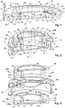
- variable focus lens of Fig. 1 is of substantially rotational-symmetric design in respect to an optical axis A. It comprises a housing 1 having a radially extending bottom section 2 with a first circular opening 3, a cylindrical, axially extending outer wall 4 and a cylindrical, axially extending inner wall or holder 5. A transparent first window 6 is held in housing 1 and closes first circular opening 3.
- the lens further comprises an actuator 8 having a radially extending top section 9 with a second circular opening 10 and a cylindrical, axially extending outer wall 11.
- a transparent second window 12 is held in actuator 8 and closes second circular opening 10.
- the transparent second window 12 and the top section 9 can also be made out of one material and be one single component.
- a flexible, elastic foil 14 extends between housing 1 and actuator 8 and forms a plurality of membranes. These membranes include:
- Second region 18, where first and second auxiliary membrane 17, 19 are connected to actuator 8, also extends around optical axis A and forms a sealing connection between actuator 8 and both auxiliary membranes 17, 19.
- second region 18 is at a larger distance from optical axis A than first region 16
- third region 20 is at a larger distance from optical axis A than second region 18. All regions 16, 18, 20 are, in the present embodiment, substantially concentric to axis A and give rise to an annular layout of the first and second auxiliary membranes 19, 17.
- the first and third regions 16, 20 are advantageously in a common plane extending perpendicularly to optical axis A, thereby making it easier to attach the foil forming the membranes to housing 1.
- the axial position of second region 18 in respect to this plane depends on the mutual positions of actuator 8 and housing 1.
- At least one passage 22 is formed in holder 5 or between holder 5 and first window 6, providing a communication between a space 24 between primary membrane 15 and window 6 and at least a space 26 between first auxiliary membrane 19 and housing 1. (In the present embodiment, space 26 also extends into a region between second auxiliary membrane 17 and housing 1.)
- at least one passage 28 is formed between the top of holder 5 of housing 1 and the actuator 8 or second window 12, providing a communication between a space 30 between primary membrane 15 and second window 12 and a space 32 between second auxiliary membrane 17 and actuator 8.
- first chamber 24, 26 is filled with a first liquid having a first refractive index and second chamber 30, 32 is filled with a second liquid having a second, different refractive index.
- Both liquids advantageously have substantially equal densities, i.e. densities that differs not more than 20%, in particular not more than 10% and advantageously but not necessary, the two liquids are immiscible
- Actuator 8 is displaceable, along optical axis A, with respect to housing 1.
- a mechanism 40 can be provided, which moves housing 1 or actuator 8, or both.
- Mechanism 40 can be a manually operated mechanism or an electrically operated mechanism.
- the electrically operated mechanism can include one or more of the following actuator types:
- actuator 8 When actuator 8 is displaced axially with respect to housing 1, the volumes of spaces 26 and 32 vary oppositely, which in turn causes the first and second liquid to flow radially in or out of the spaces 24, 30, respectively, thereby giving rise to a change of deformation of primary membrane 15. This allows to change the focal length of the lens.
- first auxiliary membrane 19 is arranged at a larger radial distance from optical axis A than second auxiliary membrane 17.
- First auxiliary membrane 19 is bordering, at its top side, on environmental air, while its bottom side faces the first liquid. It forms a first wall section of first chamber 24, 26.
- Second auxiliary membrane 17 is bordering, at its top side, on the second liquid, while its bottom side is in contact with the first liquid. It forms a first wall section of second chamber 30, 32. In the embodiment of Fig. 1 , it also forms a wall section of first chamber 24, 26.
- auxiliary membranes 19, 17, advantageously both auxiliary membranes 19, 17, is/are in contact with the environment by means of a suitable opening 21 in or between housing 1 and/or holder 8.
- Housing 1 forms a second wall section of first chamber 24, 26, namely with its bottom wall 2, and its outer wall 4.
- Window 6 forms a third wall section of first chamber 24, 26.
- actuator 8 forms a second wall section of second chamber 30, 32, namely with its top wall 9 and its outer wall 11, while window 12 finally forms a third wall section of second chamber 30, 32.
- first chamber 24, 26 as well as second chamber 30, 32 are surrounded by rigid wall sections (formed by housing 1, actuator 8 and their windows 6 and 12, respectively), as well as by flexible wall sections formed by the auxiliary membranes.
- rigid wall sections formed by housing 1, actuator 8 and their windows 6 and 12, respectively
- flexible wall sections formed by the auxiliary membranes.
- FIG. 2 A second embodiment is shown in Figs. 2 and 3 . In the following, only the differences with respect to the first embodiment are described.
- first and second auxiliary membranes 19, 17 are not arranged in an annular layout with one membrane at a larger distance from axis A than the other. Rather, as shown in Figs. 2 and 3 , the first and second auxiliary membranes 19, 17 are arranged on a common annular region in alternating fashion when viewed in azimuthal direction. They are meeting at radial wall sections 40a, 40b of housing 1.
- housing 1 has two-part form, with a first, bottom section 1a and a second, top section 1b rigidly connected to each other, with the foil forming the membranes arranged between them. Both sections 1a, 1b together form holder 5 by means of inner wall sections 5a, 5b.
- the radial sections 40a, 40b are extending radially away from inner wall sections 5a, 5b, respectively.
- Each pair of two wall sections 40a is interconnected by an outer wall section 4a, and each pair of two wall sections 40b is interconnected by an outer wall section 4b.
- Each space 26 is enclosed by two radial wall sections 40a, their connecting outer wall section 4a, bottom 2 and first auxiliary membrane 19.
- Each space 32 is enclosed by two radial wall sections 40b, their connecting outer wall section 4b, a top section 42 of housing 1, as well as second auxiliary membrane 17.
- each auxiliary membrane is facing environmental air, while, on the other side, it is facing its respective liquid.
- the first auxiliary membranes 19 are facing air on their top sides
- the second auxiliary membranes 17 are facing air on their bottom sides.
- passages 22 and 28 are provided for connecting the central spaces 24 and 30 to the spaces 26 and 32, respectively.
- Actuator 8 is also made of two parts 8a, 8b, respectively, which are fixedly connected to each other. It forms an annular body 44, from which a plurality of arms 46a, 46b extends inwards between the radial wall sections 40a, 40b, respectively for contacting the first and second auxiliary membranes 19 and 17.
- a set of bottom arms 46a mounted to bottom part 8a of actuator 8 which is connected to the bottom sides of the second auxiliary membranes 17, and there is a set of top arms 46b mounted to top part 8b of actuator, which is connected to the top sides of the first auxiliary membranes 19.
- both windows 6 and 12 are connected to housing 1, i.e. the lens has constant axial extension even when changing its focal length. It is also possible to have housing 1 and window 12 to be only one part.
- Each window 6, 12 again forms a "third wall section" for its respective first and second chamber, with the first wall section being formed by the auxiliary membranes 19 or 17 and the second wall section by housing 1.
- the advantage of this embodiment is a more compact radial design and the separation of the lens section from the moveable actuator.
- variable focus lens is of substantially rotational-symmetric design.
- the central region covered by the primary membrane is rotational-symmetric with respect to the optical axis of the lens, thereby providing a lens with rotationally-symmetric properties.
- different designs can be used.
- the auxiliary membranes can also be placed at any radial and axial distance from the primary membrane and completely or partially surround the primary membrane. Also, e.g. for a cylindrical lens, the region of the primary membrane is typically not rotational-symmetric.
- actuator 8 is connected to both of the auxiliary membranes. However, e.g. in the embodiment of Fig. 2 and 3 , it may also be connected to only one of them.
- the housing 1, actuator 8 and windows 6 and 12 can contain optical elements with suitable shapes e.g. be:
- any of the following methods can e.g. be used to form the anti-reflection coating:
- the material for the housing 1, actuator 8 and windows 6 and 12 can e.g. comprise or consist of:
- the material for the first and second liquids can be transparent, semi-transparent, absorbing or reflecting and e.g. comprise or consist of:
- the material for the elastic foil 14 can e.g. comprise or consist of:
- the adjustable optical lens can be used in a large variety of applications, such as:
- foil 14 is permeable or semi-permeable for gases, in particular for the gas used as environmental gas during manufacturing, such that bubbles of gas enclosed in the first or second chamber can easily diffuse through the membranes.
Landscapes
- Physics & Mathematics (AREA)
- General Physics & Mathematics (AREA)
- Optics & Photonics (AREA)
- Engineering & Computer Science (AREA)
- Health & Medical Sciences (AREA)
- Manufacturing & Machinery (AREA)
- Ophthalmology & Optometry (AREA)
- Mechanical Engineering (AREA)
- Mechanical Light Control Or Optical Switches (AREA)
- Lens Barrels (AREA)
- Automatic Focus Adjustment (AREA)
Claims (15)
- Linse mit veränderlichem Fokus, umfassend:- eine erste Kammer (24, 26), die mit einer ersten Flüssigkeit gefüllt ist,- eine zweite Kammer (30, 32), die mit einer zweiten Flüssigkeit gefüllt ist, wobei die zweite Flüssigkeit unterschiedliche optische Eigenschaften als die erste Flüssigkeit aufweist,- eine Hauptmembran (15), die die erste und die zweite Kammer (24, 26; 30, 32) trennt und mit der ersten und der zweiten Flüssigkeit in Kontakt ist, wobei die Hauptmembran (15) eine Linsenoberfläche bildet, die eine optische Achse (A) der Linse mit veränderlichem Fokus schneidet,- eine erste Nebenmembran (19), die einen ersten Wandabschnitt der ersten Kammer (24, 26) bildet, und- eine zweite Nebenmembran (17), die einen ersten Wandabschnitt der zweiten Kammer (30, 32) bildet,- ein Gehäuse (1), das einen zweiten Wandabschnitt von mindestens der ersten und/oder der zweiten Kammer (30, 32) bildet, und- einen Aktuator (8), der mit mindestens einer von den Membranen verbunden ist,wobei der Aktuator (8) und das Gehäuse (1) gegenseitig in eine Richtung parallel zu der optischen Achse (A) verlagerbar sind, wobei eine gegenseitige Verlagerung des Aktuators (8) und des Gehäuses (1) bewirkt, dass die Membranen sich verformen, wodurch die Brennweite der Linse geändert wird,
dadurch gekennzeichnet, dass
mindestens eine von den Nebenmembranen (19, 17) Umgebungsluft zugewandt ist, dadurch, dass die Linse mit veränderlichem Fokus eine Folie (14) umfasst, die die Hauptmembran (15) sowie die Nebenmembranen (19, 17) bildet, und dadurch, dass die Folie (14) gegenüber Gasen durchlässig oder teildurchlässig ist, um Restgas unter Verwendung von Diffusion von der ersten und der zweiten Kammer zu entfernen. - Linse nach Anspruch 1, wobei mindestens eine von den Nebenmembranen (19, 17) mittels einer Öffnung (21) in oder zwischen dem Gehäuse (1) und/oder dem Halter (8) mit der Umgebung verbunden ist.
- Linse nach einem der vorhergehenden Ansprüche, wobei die Hauptmembran (15) und/oder die Nebenmembranen (19, 17) vorgedehnt ist/sind.
- Linse nach einem der vorhergehenden Ansprüche, wobei die erste und die zweite Flüssigkeit unvermischbar sind.
- Linse nach einem der vorhergehenden Ansprüche, wobei der Aktuator (8) mit mindestens einer von den Nebenmembranen (19, 17) verbunden ist.
- Linse nach Anspruch 5, wobei der Aktuator (8) mit der ersten und der zweiten Nebenmembran (19, 17) verbunden ist.
- Linse nach einem der vorhergehenden Ansprüche, wobei das Gehäuse (1) einen Halter (5; 5a, 5b) umfasst, der mit der Hauptmembran (15) in einer ersten Region (16) verbunden ist, die sich um die optische Achse (A) erstreckt.
- Linse nach Anspruch 7, wobei der Aktuator (8) mit der ersten und der zweiten Nebenmembran (19, 17) in einer zweiten Region (18) verbunden ist, die sich um die optische Achse (A) erstreckt, wobei die zweite Region (18) sich in einem größeren Abstand von der optischen Achse (A) entfernt befindet als die erste Region (16).
- Linse nach Anspruch 8, wobei das Gehäuse (1) mit der ersten Nebenmembran (19) in einer dritten Region (20) verbunden ist, die sich um die optische Achse (A) herum erstreckt, wobei die dritte Region (20) sich in einem größeren Abstand von der optischen Achse (A) befindet als die zweite Region (18) und die erste und die dritte Region (16, 20) sich insbesondere in einer gemeinsamen Ebene befinden, die sich senkrecht zu der optischen Achse (A) erstreckt.
- Linse nach einem der vorhergehenden Ansprüche, wobei die erste und die zweite Nebenmembran (19, 17) in einem radialen Abstand von der optischen Achse (A) angeordnet sind.
- Linse nach einem der vorhergehenden Ansprüche, wobei die erste Nebenmembran (19) in einem größeren radialen Abstand von der optischen Achse (A) angeordnet ist als die zweite Nebenmembran (17).
- Linse nach einem der Ansprüche 1 bis 10, wobei die erste und die zweite Nebenmembran (19, 17) in einer ringförmigen Region um die optische Achse (A) herum angeordnet sind und wobei die erste und die zweite Nebenmembran (19, 17) sich an radialen Wandabschnitten (40a, 40b) des Gehäuses (1) treffen.
- Linse nach Anspruch 12, wobei der Aktuator (8) Arme (46a, 46b) umfasst, die sich zwischen den radialen Wandabschnitten (40a, 40b) radial nach innen erstrecken und die erste und/oder zweite Nebenmembran (19, 17) berühren.
- Linse nach einem der vorhergehenden Ansprüche, überdies umfassend:ein erstes Fenster (8), das einen dritten Wandabschnitt der ersten Kammer (24, 26) bildet und an dem Gehäuse (1) montiert ist, undein zweites Fenster (12), das einen dritten Wandabschnitt der zweiten Kammer (30, 32) bildet und an dem Aktuator (8) montiert ist.
- Verfahren zum Herstellen der Linse mit veränderlichem Fokus nach einem der vorhergehenden Ansprüche, das die folgenden Schritte umfasst:- Füllen der zweiten Flüssigkeit in die zweite Kammer (30, 32),- Entfernen von Restgas von der zweiten Kammer (30, 32) unter Verwendung von Diffusion des Gases durch die Folie (14),- Füllen der ersten Flüssigkeit in die erste Kammer (24, 26), und- Entfernen von Restgas von der ersten Kammer unter Verwendung von Diffusion des Gases durch die Folie (14),wobei die Folie die Membranen bildet.
Applications Claiming Priority (1)
| Application Number | Priority Date | Filing Date | Title |
|---|---|---|---|
| PCT/CH2010/000270 WO2012055049A1 (en) | 2010-10-26 | 2010-10-26 | Variable focus lens having two liquid chambers |
Publications (2)
| Publication Number | Publication Date |
|---|---|
| EP2633341A1 EP2633341A1 (de) | 2013-09-04 |
| EP2633341B1 true EP2633341B1 (de) | 2019-12-25 |
Family
ID=43971198
Family Applications (1)
| Application Number | Title | Priority Date | Filing Date |
|---|---|---|---|
| EP10775691.8A Active EP2633341B1 (de) | 2010-10-26 | 2010-10-26 | Linse mit veränderlichem fokus mit zwei flüssigkeitskammern |
Country Status (6)
| Country | Link |
|---|---|
| US (1) | US8947784B2 (de) |
| EP (1) | EP2633341B1 (de) |
| JP (1) | JP2014500522A (de) |
| KR (1) | KR20130139952A (de) |
| CN (1) | CN103180762A (de) |
| WO (1) | WO2012055049A1 (de) |
Families Citing this family (34)
| Publication number | Priority date | Publication date | Assignee | Title |
|---|---|---|---|---|
| CA2810754A1 (en) * | 2012-03-30 | 2013-09-30 | Johnson & Johnson Vision Care, Inc. | Method and apparatus for a variable power ophthalmic lens |
| ES2535126B1 (es) | 2013-10-01 | 2016-03-17 | Consejo Superior De Investigaciones Científicas (Csic) | Instrumento miniaturizado simulador de visión simultánea |
| KR102177133B1 (ko) | 2014-01-31 | 2020-11-10 | 매직 립, 인코포레이티드 | 멀티-포컬 디스플레이 시스템 및 방법 |
| EP4099274B1 (de) | 2014-01-31 | 2024-03-06 | Magic Leap, Inc. | Multifokales anzeigesystem und verfahren |
| WO2015184409A1 (en) | 2014-05-30 | 2015-12-03 | Magic Leap, Inc. | Methods and systems for displaying stereoscopy with a freeform optical system with addressable focus for virtual and augmented reality |
| EP3149528B1 (de) * | 2014-05-30 | 2023-06-07 | Magic Leap, Inc. | Verfahren und system zur erzeugung von fokalebenen in virtueller und erweiterter realität |
| EP3062142B1 (de) | 2015-02-26 | 2018-10-03 | Nokia Technologies OY | Vorrichtung für augennahe Anzeige |
| DE102015209418A1 (de) | 2015-05-22 | 2016-11-24 | Robert Bosch Gmbh | Scanvorrichtung und Scanverfahren |
| FR3053800B1 (fr) | 2016-07-08 | 2019-06-07 | Laclaree | Verres ophtalmiques avec controle dynamique de focale |
| US9977216B2 (en) | 2016-07-14 | 2018-05-22 | Microsoft Technology Licensing, Llc | Passive lens athermalization using liquid lens |
| US10786959B2 (en) * | 2016-07-18 | 2020-09-29 | Johnson & Johnson Vision Care, Inc | Mold for contact lens with non-rotationally symmetric rim or edge |
| CN109791270A (zh) * | 2016-08-12 | 2019-05-21 | 奥普托图尼康苏默尔股份公司 | 光学设备,特别是相机,特别是包括自动聚焦和图像稳定的相机 |
| US10650552B2 (en) | 2016-12-29 | 2020-05-12 | Magic Leap, Inc. | Systems and methods for augmented reality |
| EP3343267B1 (de) | 2016-12-30 | 2024-01-24 | Magic Leap, Inc. | Polychromatische lichtauskopplungsvorrichtung, augennahe anzeige damit und verfahren zur polychromatischem lichtauskopplung |
| CN110546543B (zh) * | 2017-02-09 | 2022-03-08 | 康宁股份有限公司 | 液体透镜 |
| CN106990459B (zh) * | 2017-05-09 | 2018-11-09 | 宁波大学 | 一种具有多层结构的柔性可调透镜及变倍光学系统 |
| US11300479B2 (en) | 2017-06-28 | 2022-04-12 | Consejo Superior De Investigaciones Científicas | Device for determining the optical power of lenses and measurement method |
| US10578870B2 (en) | 2017-07-26 | 2020-03-03 | Magic Leap, Inc. | Exit pupil expander |
| WO2019113570A1 (en) | 2017-12-10 | 2019-06-13 | Magic Leap, Inc. | Anti-reflective coatings on optical waveguides |
| EP3729172A4 (de) | 2017-12-20 | 2021-02-24 | Magic Leap, Inc. | Einsatz für eine ansichtsvorrichtung für erweiterte realität |
| WO2019178567A1 (en) | 2018-03-15 | 2019-09-19 | Magic Leap, Inc. | Image correction due to deformation of components of a viewing device |
| CN110441903A (zh) * | 2018-05-04 | 2019-11-12 | 中强光电股份有限公司 | 可变焦距光学元件 |
| KR20190133544A (ko) | 2018-05-23 | 2019-12-03 | 엘지이노텍 주식회사 | 액체 렌즈 및 이를 포함하는 렌즈 어셈블리 |
| US11204491B2 (en) * | 2018-05-30 | 2021-12-21 | Magic Leap, Inc. | Compact variable focus configurations |
| EP3803450A4 (de) | 2018-05-31 | 2021-08-18 | Magic Leap, Inc. | Positionsbestimmung eines radarkopfes |
| EP3584610A1 (de) * | 2018-06-19 | 2019-12-25 | Essilor International | Abstimmbares optisches system und verfahren zur bestimmung der geometrie eines deckglases in besagtem abstimmbarem optischem system |
| US11856479B2 (en) | 2018-07-03 | 2023-12-26 | Magic Leap, Inc. | Systems and methods for virtual and augmented reality along a route with markers |
| EP3830631A4 (de) | 2018-08-03 | 2021-10-27 | Magic Leap, Inc. | Auf einer nichtfusionierten pose basierte driftkorrektur eines fusionierten totems in einem benutzerinteraktionssystem |
| CN112771415A (zh) * | 2018-08-22 | 2021-05-07 | 奥普托图尼股份公司 | 与取向无关的彗差补偿液体透镜 |
| DE102019202707A1 (de) | 2019-02-28 | 2020-09-17 | Volkswagen Aktiengesellschaft | Verfahren zum Betreiben eines Verbrennungsmotors, Steuergerät, und elektrisch angetriebene Ladeeinrichtung |
| EP3939030A4 (de) | 2019-03-12 | 2022-11-30 | Magic Leap, Inc. | Registrierung lokaler inhalte zwischen ersten und zweiten betrachtern der erweiterten realität |
| GB2588466A (en) * | 2019-10-25 | 2021-04-28 | Coopervision Int Ltd | Tuneable ophthalmic lens |
| JP2023502927A (ja) | 2019-11-15 | 2023-01-26 | マジック リープ, インコーポレイテッド | 外科手術環境において使用するための視認システム |
| US20230134656A1 (en) * | 2019-12-20 | 2023-05-04 | Optotune Consumer Ag | Liquid lens having a fixed lens shaping element and a movable transparent window |
Family Cites Families (73)
| Publication number | Priority date | Publication date | Assignee | Title |
|---|---|---|---|---|
| US60109A (en) | 1866-11-27 | woodward | ||
| US2062468A (en) | 1934-07-26 | 1936-12-01 | Edwin H Land | Optical device |
| GB1327503A (en) | 1971-02-05 | 1973-08-22 | Bosch Gmbh Robert | Optical lenses |
| US4494826A (en) | 1979-12-31 | 1985-01-22 | Smith James L | Surface deformation image device |
| US4572616A (en) | 1982-08-10 | 1986-02-25 | Syracuse University | Adaptive liquid crystal lens |
| US4783155A (en) | 1983-10-17 | 1988-11-08 | Canon Kabushiki Kaisha | Optical device with variably shaped optical surface and a method for varying the focal length |
| JPS60220301A (ja) | 1984-04-17 | 1985-11-05 | Canon Inc | 可変焦点光学素子 |
| US4802746A (en) | 1985-02-26 | 1989-02-07 | Canon Kabushiki Kaisha | Variable-focus optical element and focus detecting device utilizing the same |
| JPS62148903A (ja) | 1985-12-24 | 1987-07-02 | Canon Inc | 可変焦点光学素子 |
| JPH01166003A (ja) | 1987-12-22 | 1989-06-29 | Fuji Photo Film Co Ltd | 光学素子 |
| JPH01166004A (ja) | 1987-12-22 | 1989-06-29 | Fuji Photo Film Co Ltd | 光学素子 |
| US5138494A (en) | 1990-05-07 | 1992-08-11 | Stephen Kurtin | Variable focal length lens |
| US5438486A (en) | 1992-07-20 | 1995-08-01 | Mcnair; Edward P. | Headlights with variably shaped optical elements |
| JP3480071B2 (ja) | 1994-10-13 | 2003-12-15 | 株式会社デンソー | 可変焦点レンズ |
| US5999328A (en) | 1994-11-08 | 1999-12-07 | Kurtin; Stephen | Liquid-filled variable focus lens with band actuator |
| JP3206420B2 (ja) | 1996-02-22 | 2001-09-10 | 株式会社デンソー | カメラ装置 |
| US5774273A (en) | 1996-08-23 | 1998-06-30 | Vari-Lite, Inc. | Variable-geometry liquid-filled lens apparatus and method for controlling the energy distribution of a light beam |
| WO1998011458A1 (en) * | 1996-09-13 | 1998-03-19 | Joshua David Silver | Improvements in or relating to variable focus lenses |
| JP3400270B2 (ja) | 1996-11-08 | 2003-04-28 | 株式会社デンソー | 積層型圧電アクチュエータおよび可変焦点レンズ装置 |
| JPH11133210A (ja) | 1997-10-30 | 1999-05-21 | Denso Corp | 可変焦点レンズ |
| US6040947A (en) | 1998-06-09 | 2000-03-21 | Lane Research | Variable spectacle lens |
| JP4144079B2 (ja) | 1998-09-04 | 2008-09-03 | 株式会社デンソー | 可変焦点レンズ |
| WO2002014926A2 (en) * | 2000-08-15 | 2002-02-21 | Nanostream, Inc. | Optical devices with fluidic systems |
| US7672059B2 (en) | 2000-10-20 | 2010-03-02 | Holochip Corporation | Fluidic lens with electrostatic actuation |
| US7646544B2 (en) | 2005-05-14 | 2010-01-12 | Batchko Robert G | Fluidic optical devices |
| JP2002131513A (ja) | 2000-10-27 | 2002-05-09 | Fuji Photo Film Co Ltd | 焦点距離可変レンズ |
| US7405884B2 (en) | 2000-12-21 | 2008-07-29 | Olympus Corporation | Optical apparatus |
| GB0100031D0 (en) | 2001-01-02 | 2001-02-14 | Silver Joshua D | Variable focus optical apparatus |
| JP2002357774A (ja) | 2001-03-28 | 2002-12-13 | Olympus Optical Co Ltd | 可変焦点光学素子 |
| US6747806B2 (en) | 2001-04-19 | 2004-06-08 | Creo Srl | Method for controlling light beam using adaptive micro-lens |
| US6538823B2 (en) | 2001-06-19 | 2003-03-25 | Lucent Technologies Inc. | Tunable liquid microlens |
| US6542309B2 (en) | 2001-06-29 | 2003-04-01 | The Boeing Company | Flexible lens |
| JP3687585B2 (ja) | 2001-10-05 | 2005-08-24 | オムロン株式会社 | 焦点可変レンズ装置 |
| US6715876B2 (en) | 2001-11-19 | 2004-04-06 | Johnnie E. Floyd | Lens arrangement with fluid cell and prescriptive element |
| US6860601B2 (en) | 2002-02-06 | 2005-03-01 | John H. Shadduck | Adaptive optic lens system and method of use |
| US6864951B1 (en) | 2002-05-08 | 2005-03-08 | University Of Central Florida | Tunable electronic lens and prisms using inhomogeneous nano scale liquid crystal droplets |
| US20040001180A1 (en) | 2002-07-01 | 2004-01-01 | Saul Epstein | Variable focus lens with internal refractive surface |
| US6966649B2 (en) | 2002-08-12 | 2005-11-22 | John H Shadduck | Adaptive optic lens system and method of use |
| CN1732401A (zh) | 2002-12-30 | 2006-02-08 | 皇家飞利浦电子股份有限公司 | 含有聚合物致动器的光学装置 |
| US6891682B2 (en) | 2003-03-03 | 2005-05-10 | Lucent Technologies Inc. | Lenses with tunable liquid optical elements |
| CA2517576A1 (en) | 2003-03-06 | 2004-09-23 | John H. Shadduck | Adaptive optic lens and method of making |
| US7079203B1 (en) | 2003-06-23 | 2006-07-18 | Research Foundation Of The University Of Central Florida, Inc. | Electrically tunable polarization-independent micro lens using polymer network twisted nematic liquid crystal |
| JP2005092175A (ja) | 2003-08-08 | 2005-04-07 | Olympus Corp | 光学特性可変光学素子 |
| WO2005040909A1 (en) | 2003-10-09 | 2005-05-06 | E-Vision, Llc | Improved hybrid electro-active lens |
| US6859333B1 (en) | 2004-01-27 | 2005-02-22 | Research Foundation Of The University Of Central Florida | Adaptive liquid crystal lenses |
| DE102004011026A1 (de) | 2004-03-04 | 2005-09-29 | Siemens Ag | Adaptives optisches Element mit einem Polymeraktor |
| US7453646B2 (en) | 2004-03-31 | 2008-11-18 | The Regents Of The University Of California | Fluidic adaptive lens systems and methods |
| US7675686B2 (en) | 2004-03-31 | 2010-03-09 | The Regents Of The University Of California | Fluidic adaptive lens |
| GB0407414D0 (en) | 2004-04-01 | 2004-05-05 | 1 Ltd | Variable focal length lens |
| GB0423564D0 (en) | 2004-06-01 | 2004-11-24 | Koninkl Philips Electronics Nv | Optical element |
| US7298970B2 (en) | 2004-08-30 | 2007-11-20 | Eastman Kodak Company | Zoom flash with variable focus lens |
| US7826145B2 (en) | 2004-11-05 | 2010-11-02 | The Regents Of The University Of California | Fluidic adaptive lens systems with pumping systems |
| US8885139B2 (en) | 2005-01-21 | 2014-11-11 | Johnson & Johnson Vision Care | Adaptive electro-active lens with variable focal length |
| US7142369B2 (en) | 2005-01-21 | 2006-11-28 | Research Foundation Of The University Of Central Florida, Inc. | Variable focus liquid lens |
| US7697214B2 (en) | 2005-05-14 | 2010-04-13 | Holochip Corporation | Fluidic lens with manually-adjustable focus |
| EP1905256B1 (de) * | 2005-07-15 | 2013-05-15 | Research In Motion Limited | Verfahren und vorrichtungen zum bereitstellen von ptt-datenpufferungs-unterstützungsindikationen aus mobilen einrichtungen und ptt-datenpufferungssteuerung durch drahtlose netze |
| JP4697786B2 (ja) | 2005-08-23 | 2011-06-08 | セイコープレシジョン株式会社 | 可変焦点レンズとこれを用いた焦点調節装置及び撮像装置 |
| US7382976B1 (en) | 2005-09-09 | 2008-06-03 | Avago Technologies Ecb4 Ip Pte Ltd | Light source having a variable focal length |
| GB0522030D0 (en) * | 2005-10-28 | 2005-12-07 | Silver Joshua D | Variable focus lens |
| US7768712B2 (en) | 2005-10-28 | 2010-08-03 | J & J Technologies Limited | Variable focus lens |
| EP1816493A1 (de) | 2006-02-07 | 2007-08-08 | ETH Zürich | Abstimmbares Diffraktionsgitter |
| JP4209936B2 (ja) | 2006-08-10 | 2009-01-14 | パナソニック株式会社 | 可変焦点レンズ装置 |
| WO2008020356A1 (en) | 2006-08-15 | 2008-02-21 | Koninklijke Philips Electronics N.V. | Variable focus lens |
| JP2008058841A (ja) | 2006-09-02 | 2008-03-13 | Wakayama Univ | 可変形状液体型の可変焦点レンズ |
| KR20080043106A (ko) | 2006-11-13 | 2008-05-16 | 삼성전자주식회사 | 광학렌즈 및 그 제조방법 |
| US7813047B2 (en) | 2006-12-15 | 2010-10-12 | Hand Held Products, Inc. | Apparatus and method comprising deformable lens element |
| US7729068B2 (en) | 2007-02-27 | 2010-06-01 | Konica Minolta Holdings, Inc. | Polymer actuator and optical unit |
| EP2034338A1 (de) * | 2007-08-11 | 2009-03-11 | ETH Zurich | Flüssiglinsesystem |
| EP2075630A1 (de) | 2007-12-28 | 2009-07-01 | Varioptic | Adaptive Beleuchtungsvorrichtung |
| FR2930352B1 (fr) | 2008-04-21 | 2010-09-17 | Commissariat Energie Atomique | Membrane perfectionnee notamment pour dispositif optique a membrane deformable |
| WO2010015093A1 (en) | 2008-08-08 | 2010-02-11 | Optotune Ag | Electroactive optical device |
| FR2938349B1 (fr) | 2008-11-07 | 2011-04-15 | Commissariat Energie Atomique | Dispositif optique a membrane deformable a actionnement perfectionne |
| EP2239600A1 (de) | 2010-06-02 | 2010-10-13 | Optotune AG | Einstellbare optische Linse |
-
2010
- 2010-10-26 WO PCT/CH2010/000270 patent/WO2012055049A1/en active Application Filing
- 2010-10-26 CN CN2010800697650A patent/CN103180762A/zh active Pending
- 2010-10-26 JP JP2013535225A patent/JP2014500522A/ja active Pending
- 2010-10-26 EP EP10775691.8A patent/EP2633341B1/de active Active
- 2010-10-26 US US13/823,034 patent/US8947784B2/en active Active
- 2010-10-26 KR KR1020137010654A patent/KR20130139952A/ko not_active Application Discontinuation
Non-Patent Citations (1)
| Title |
|---|
| None * |
Also Published As
| Publication number | Publication date |
|---|---|
| WO2012055049A1 (en) | 2012-05-03 |
| US8947784B2 (en) | 2015-02-03 |
| CN103180762A (zh) | 2013-06-26 |
| US20130265647A1 (en) | 2013-10-10 |
| EP2633341A1 (de) | 2013-09-04 |
| JP2014500522A (ja) | 2014-01-09 |
| KR20130139952A (ko) | 2013-12-23 |
Similar Documents
| Publication | Publication Date | Title |
|---|---|---|
| EP2633341B1 (de) | Linse mit veränderlichem fokus mit zwei flüssigkeitskammern | |
| CN105005103B (zh) | 可调的光学透镜 | |
| EP3032297B1 (de) | Flüssiglinsensystem | |
| US8699141B2 (en) | Lens assembly apparatus and method | |
| EP3304138B1 (de) | Optische vorrichtung mit variabler öffnung | |
| Zeng et al. | Liquid tunable microlenses based on MEMS techniques | |
| US20080316587A1 (en) | Solution Flow Prevention in Fluid Focus Lenses | |
| WO2008138010A1 (en) | Fluidic lens with electrostatic actuation | |
| EP2282226A1 (de) | Einstellbares optische Diaphragma | |
| Jiang et al. | Microlenses: Properties, Fabrication and Liquid Lenses | |
| US20230347604A1 (en) | Rapid prototyping of optical components, particularly lenses, for producing customized optical surface shapes | |
| Zappe | Micro-optics: a micro-tutorial | |
| WO2015022027A1 (en) | Fluidically controlled optical router | |
| Seo et al. | Adjustable tilt angle of liquid microlens with four coplanar electrodes | |
| Müller | Tunable optofluidic apertures | |
| Mönch | 3 Soft-Matter Micro-optics | |
| Zou et al. | MEMS tunable optics | |
| MIN | A Study on the Development on Tunable Opto-Fluidic Devices by Diamond Turning and Soft Lithography |
Legal Events
| Date | Code | Title | Description |
|---|---|---|---|
| PUAI | Public reference made under article 153(3) epc to a published international application that has entered the european phase |
Free format text: ORIGINAL CODE: 0009012 |
|
| 17P | Request for examination filed |
Effective date: 20130305 |
|
| AK | Designated contracting states |
Kind code of ref document: A1 Designated state(s): AL AT BE BG CH CY CZ DE DK EE ES FI FR GB GR HR HU IE IS IT LI LT LU LV MC MK MT NL NO PL PT RO RS SE SI SK SM TR |
|
| DAX | Request for extension of the european patent (deleted) | ||
| RAP1 | Party data changed (applicant data changed or rights of an application transferred) |
Owner name: OPTOTUNE AG |
|
| GRAP | Despatch of communication of intention to grant a patent |
Free format text: ORIGINAL CODE: EPIDOSNIGR1 |
|
| STAA | Information on the status of an ep patent application or granted ep patent |
Free format text: STATUS: GRANT OF PATENT IS INTENDED |
|
| INTG | Intention to grant announced |
Effective date: 20180827 |
|
| GRAJ | Information related to disapproval of communication of intention to grant by the applicant or resumption of examination proceedings by the epo deleted |
Free format text: ORIGINAL CODE: EPIDOSDIGR1 |
|
| STAA | Information on the status of an ep patent application or granted ep patent |
Free format text: STATUS: REQUEST FOR EXAMINATION WAS MADE |
|
| INTC | Intention to grant announced (deleted) | ||
| GRAP | Despatch of communication of intention to grant a patent |
Free format text: ORIGINAL CODE: EPIDOSNIGR1 |
|
| STAA | Information on the status of an ep patent application or granted ep patent |
Free format text: STATUS: GRANT OF PATENT IS INTENDED |
|
| INTG | Intention to grant announced |
Effective date: 20190703 |
|
| GRAS | Grant fee paid |
Free format text: ORIGINAL CODE: EPIDOSNIGR3 |
|
| GRAA | (expected) grant |
Free format text: ORIGINAL CODE: 0009210 |
|
| STAA | Information on the status of an ep patent application or granted ep patent |
Free format text: STATUS: THE PATENT HAS BEEN GRANTED |
|
| AK | Designated contracting states |
Kind code of ref document: B1 Designated state(s): AL AT BE BG CH CY CZ DE DK EE ES FI FR GB GR HR HU IE IS IT LI LT LU LV MC MK MT NL NO PL PT RO RS SE SI SK SM TR |
|
| REG | Reference to a national code |
Ref country code: GB Ref legal event code: FG4D |
|
| REG | Reference to a national code |
Ref country code: CH Ref legal event code: EP |
|
| REG | Reference to a national code |
Ref country code: DE Ref legal event code: R096 Ref document number: 602010062521 Country of ref document: DE |
|
| REG | Reference to a national code |
Ref country code: AT Ref legal event code: REF Ref document number: 1217748 Country of ref document: AT Kind code of ref document: T Effective date: 20200115 |
|
| REG | Reference to a national code |
Ref country code: IE Ref legal event code: FG4D |
|
| REG | Reference to a national code |
Ref country code: NL Ref legal event code: MP Effective date: 20191225 |
|
| PG25 | Lapsed in a contracting state [announced via postgrant information from national office to epo] |
Ref country code: FI Free format text: LAPSE BECAUSE OF FAILURE TO SUBMIT A TRANSLATION OF THE DESCRIPTION OR TO PAY THE FEE WITHIN THE PRESCRIBED TIME-LIMIT Effective date: 20191225 Ref country code: BG Free format text: LAPSE BECAUSE OF FAILURE TO SUBMIT A TRANSLATION OF THE DESCRIPTION OR TO PAY THE FEE WITHIN THE PRESCRIBED TIME-LIMIT Effective date: 20200325 Ref country code: NO Free format text: LAPSE BECAUSE OF FAILURE TO SUBMIT A TRANSLATION OF THE DESCRIPTION OR TO PAY THE FEE WITHIN THE PRESCRIBED TIME-LIMIT Effective date: 20200325 Ref country code: GR Free format text: LAPSE BECAUSE OF FAILURE TO SUBMIT A TRANSLATION OF THE DESCRIPTION OR TO PAY THE FEE WITHIN THE PRESCRIBED TIME-LIMIT Effective date: 20200326 Ref country code: LT Free format text: LAPSE BECAUSE OF FAILURE TO SUBMIT A TRANSLATION OF THE DESCRIPTION OR TO PAY THE FEE WITHIN THE PRESCRIBED TIME-LIMIT Effective date: 20191225 Ref country code: LV Free format text: LAPSE BECAUSE OF FAILURE TO SUBMIT A TRANSLATION OF THE DESCRIPTION OR TO PAY THE FEE WITHIN THE PRESCRIBED TIME-LIMIT Effective date: 20191225 Ref country code: SE Free format text: LAPSE BECAUSE OF FAILURE TO SUBMIT A TRANSLATION OF THE DESCRIPTION OR TO PAY THE FEE WITHIN THE PRESCRIBED TIME-LIMIT Effective date: 20191225 |
|
| REG | Reference to a national code |
Ref country code: LT Ref legal event code: MG4D |
|
| PG25 | Lapsed in a contracting state [announced via postgrant information from national office to epo] |
Ref country code: RS Free format text: LAPSE BECAUSE OF FAILURE TO SUBMIT A TRANSLATION OF THE DESCRIPTION OR TO PAY THE FEE WITHIN THE PRESCRIBED TIME-LIMIT Effective date: 20191225 Ref country code: HR Free format text: LAPSE BECAUSE OF FAILURE TO SUBMIT A TRANSLATION OF THE DESCRIPTION OR TO PAY THE FEE WITHIN THE PRESCRIBED TIME-LIMIT Effective date: 20191225 |
|
| PG25 | Lapsed in a contracting state [announced via postgrant information from national office to epo] |
Ref country code: AL Free format text: LAPSE BECAUSE OF FAILURE TO SUBMIT A TRANSLATION OF THE DESCRIPTION OR TO PAY THE FEE WITHIN THE PRESCRIBED TIME-LIMIT Effective date: 20191225 |
|
| PG25 | Lapsed in a contracting state [announced via postgrant information from national office to epo] |
Ref country code: EE Free format text: LAPSE BECAUSE OF FAILURE TO SUBMIT A TRANSLATION OF THE DESCRIPTION OR TO PAY THE FEE WITHIN THE PRESCRIBED TIME-LIMIT Effective date: 20191225 Ref country code: PT Free format text: LAPSE BECAUSE OF FAILURE TO SUBMIT A TRANSLATION OF THE DESCRIPTION OR TO PAY THE FEE WITHIN THE PRESCRIBED TIME-LIMIT Effective date: 20200520 Ref country code: NL Free format text: LAPSE BECAUSE OF FAILURE TO SUBMIT A TRANSLATION OF THE DESCRIPTION OR TO PAY THE FEE WITHIN THE PRESCRIBED TIME-LIMIT Effective date: 20191225 Ref country code: RO Free format text: LAPSE BECAUSE OF FAILURE TO SUBMIT A TRANSLATION OF THE DESCRIPTION OR TO PAY THE FEE WITHIN THE PRESCRIBED TIME-LIMIT Effective date: 20191225 Ref country code: CZ Free format text: LAPSE BECAUSE OF FAILURE TO SUBMIT A TRANSLATION OF THE DESCRIPTION OR TO PAY THE FEE WITHIN THE PRESCRIBED TIME-LIMIT Effective date: 20191225 |
|
| PG25 | Lapsed in a contracting state [announced via postgrant information from national office to epo] |
Ref country code: SK Free format text: LAPSE BECAUSE OF FAILURE TO SUBMIT A TRANSLATION OF THE DESCRIPTION OR TO PAY THE FEE WITHIN THE PRESCRIBED TIME-LIMIT Effective date: 20191225 Ref country code: IS Free format text: LAPSE BECAUSE OF FAILURE TO SUBMIT A TRANSLATION OF THE DESCRIPTION OR TO PAY THE FEE WITHIN THE PRESCRIBED TIME-LIMIT Effective date: 20200425 Ref country code: SM Free format text: LAPSE BECAUSE OF FAILURE TO SUBMIT A TRANSLATION OF THE DESCRIPTION OR TO PAY THE FEE WITHIN THE PRESCRIBED TIME-LIMIT Effective date: 20191225 |
|
| REG | Reference to a national code |
Ref country code: DE Ref legal event code: R097 Ref document number: 602010062521 Country of ref document: DE |
|
| PG25 | Lapsed in a contracting state [announced via postgrant information from national office to epo] |
Ref country code: ES Free format text: LAPSE BECAUSE OF FAILURE TO SUBMIT A TRANSLATION OF THE DESCRIPTION OR TO PAY THE FEE WITHIN THE PRESCRIBED TIME-LIMIT Effective date: 20191225 Ref country code: DK Free format text: LAPSE BECAUSE OF FAILURE TO SUBMIT A TRANSLATION OF THE DESCRIPTION OR TO PAY THE FEE WITHIN THE PRESCRIBED TIME-LIMIT Effective date: 20191225 |
|
| PLBE | No opposition filed within time limit |
Free format text: ORIGINAL CODE: 0009261 |
|
| STAA | Information on the status of an ep patent application or granted ep patent |
Free format text: STATUS: NO OPPOSITION FILED WITHIN TIME LIMIT |
|
| REG | Reference to a national code |
Ref country code: AT Ref legal event code: MK05 Ref document number: 1217748 Country of ref document: AT Kind code of ref document: T Effective date: 20191225 |
|
| PG25 | Lapsed in a contracting state [announced via postgrant information from national office to epo] |
Ref country code: SI Free format text: LAPSE BECAUSE OF FAILURE TO SUBMIT A TRANSLATION OF THE DESCRIPTION OR TO PAY THE FEE WITHIN THE PRESCRIBED TIME-LIMIT Effective date: 20191225 |
|
| 26N | No opposition filed |
Effective date: 20200928 |
|
| PG25 | Lapsed in a contracting state [announced via postgrant information from national office to epo] |
Ref country code: AT Free format text: LAPSE BECAUSE OF FAILURE TO SUBMIT A TRANSLATION OF THE DESCRIPTION OR TO PAY THE FEE WITHIN THE PRESCRIBED TIME-LIMIT Effective date: 20191225 Ref country code: IT Free format text: LAPSE BECAUSE OF FAILURE TO SUBMIT A TRANSLATION OF THE DESCRIPTION OR TO PAY THE FEE WITHIN THE PRESCRIBED TIME-LIMIT Effective date: 20191225 |
|
| PG25 | Lapsed in a contracting state [announced via postgrant information from national office to epo] |
Ref country code: PL Free format text: LAPSE BECAUSE OF FAILURE TO SUBMIT A TRANSLATION OF THE DESCRIPTION OR TO PAY THE FEE WITHIN THE PRESCRIBED TIME-LIMIT Effective date: 20191225 |
|
| PG25 | Lapsed in a contracting state [announced via postgrant information from national office to epo] |
Ref country code: MC Free format text: LAPSE BECAUSE OF FAILURE TO SUBMIT A TRANSLATION OF THE DESCRIPTION OR TO PAY THE FEE WITHIN THE PRESCRIBED TIME-LIMIT Effective date: 20191225 Ref country code: LU Free format text: LAPSE BECAUSE OF NON-PAYMENT OF DUE FEES Effective date: 20201026 |
|
| REG | Reference to a national code |
Ref country code: BE Ref legal event code: MM Effective date: 20201031 |
|
| PG25 | Lapsed in a contracting state [announced via postgrant information from national office to epo] |
Ref country code: BE Free format text: LAPSE BECAUSE OF NON-PAYMENT OF DUE FEES Effective date: 20201031 |
|
| PG25 | Lapsed in a contracting state [announced via postgrant information from national office to epo] |
Ref country code: IE Free format text: LAPSE BECAUSE OF NON-PAYMENT OF DUE FEES Effective date: 20201026 |
|
| PGFP | Annual fee paid to national office [announced via postgrant information from national office to epo] |
Ref country code: CH Payment date: 20211020 Year of fee payment: 12 |
|
| PG25 | Lapsed in a contracting state [announced via postgrant information from national office to epo] |
Ref country code: TR Free format text: LAPSE BECAUSE OF FAILURE TO SUBMIT A TRANSLATION OF THE DESCRIPTION OR TO PAY THE FEE WITHIN THE PRESCRIBED TIME-LIMIT Effective date: 20191225 Ref country code: MT Free format text: LAPSE BECAUSE OF FAILURE TO SUBMIT A TRANSLATION OF THE DESCRIPTION OR TO PAY THE FEE WITHIN THE PRESCRIBED TIME-LIMIT Effective date: 20191225 Ref country code: CY Free format text: LAPSE BECAUSE OF FAILURE TO SUBMIT A TRANSLATION OF THE DESCRIPTION OR TO PAY THE FEE WITHIN THE PRESCRIBED TIME-LIMIT Effective date: 20191225 |
|
| PG25 | Lapsed in a contracting state [announced via postgrant information from national office to epo] |
Ref country code: MK Free format text: LAPSE BECAUSE OF FAILURE TO SUBMIT A TRANSLATION OF THE DESCRIPTION OR TO PAY THE FEE WITHIN THE PRESCRIBED TIME-LIMIT Effective date: 20191225 |
|
| REG | Reference to a national code |
Ref country code: DE Ref legal event code: R081 Ref document number: 602010062521 Country of ref document: DE Owner name: OPTOTUNE SWITZERLAND AG, CH Free format text: FORMER OWNER: OPTOTUNE AG, STANS, CH |
|
| REG | Reference to a national code |
Ref country code: CH Ref legal event code: PL |
|
| PG25 | Lapsed in a contracting state [announced via postgrant information from national office to epo] |
Ref country code: LI Free format text: LAPSE BECAUSE OF NON-PAYMENT OF DUE FEES Effective date: 20221031 Ref country code: CH Free format text: LAPSE BECAUSE OF NON-PAYMENT OF DUE FEES Effective date: 20221031 |
|
| PGFP | Annual fee paid to national office [announced via postgrant information from national office to epo] |
Ref country code: GB Payment date: 20231020 Year of fee payment: 14 |
|
| PGFP | Annual fee paid to national office [announced via postgrant information from national office to epo] |
Ref country code: FR Payment date: 20231025 Year of fee payment: 14 Ref country code: DE Payment date: 20231020 Year of fee payment: 14 |