EP2633253B1 - Schrott-schubvorrichtung - Google Patents
Schrott-schubvorrichtung Download PDFInfo
- Publication number
- EP2633253B1 EP2633253B1 EP11805382.6A EP11805382A EP2633253B1 EP 2633253 B1 EP2633253 B1 EP 2633253B1 EP 11805382 A EP11805382 A EP 11805382A EP 2633253 B1 EP2633253 B1 EP 2633253B1
- Authority
- EP
- European Patent Office
- Prior art keywords
- scrap
- piston
- cylinder
- pusher
- pushing assembly
- Prior art date
- Legal status (The legal status is an assumption and is not a legal conclusion. Google has not performed a legal analysis and makes no representation as to the accuracy of the status listed.)
- Not-in-force
Links
Images


Classifications
-
- F—MECHANICAL ENGINEERING; LIGHTING; HEATING; WEAPONS; BLASTING
- F27—FURNACES; KILNS; OVENS; RETORTS
- F27B—FURNACES, KILNS, OVENS OR RETORTS IN GENERAL; OPEN SINTERING OR LIKE APPARATUS
- F27B3/00—Hearth-type furnaces, e.g. of reverberatory type; Electric arc furnaces ; Tank furnaces
- F27B3/10—Details, accessories or equipment, e.g. dust-collectors, specially adapted for hearth-type furnaces
- F27B3/18—Arrangements of devices for charging
-
- B—PERFORMING OPERATIONS; TRANSPORTING
- B65—CONVEYING; PACKING; STORING; HANDLING THIN OR FILAMENTARY MATERIAL
- B65G—TRANSPORT OR STORAGE DEVICES, e.g. CONVEYORS FOR LOADING OR TIPPING, SHOP CONVEYOR SYSTEMS OR PNEUMATIC TUBE CONVEYORS
- B65G25/00—Conveyors comprising a cyclically-moving, e.g. reciprocating, carrier or impeller which is disengaged from the load during the return part of its movement
- B65G25/04—Conveyors comprising a cyclically-moving, e.g. reciprocating, carrier or impeller which is disengaged from the load during the return part of its movement the carrier or impeller having identical forward and return paths of movement, e.g. reciprocating conveyors
- B65G25/08—Conveyors comprising a cyclically-moving, e.g. reciprocating, carrier or impeller which is disengaged from the load during the return part of its movement the carrier or impeller having identical forward and return paths of movement, e.g. reciprocating conveyors having impellers, e.g. pushers
-
- C—CHEMISTRY; METALLURGY
- C02—TREATMENT OF WATER, WASTE WATER, SEWAGE, OR SLUDGE
- C02F—TREATMENT OF WATER, WASTE WATER, SEWAGE, OR SLUDGE
- C02F1/00—Treatment of water, waste water, or sewage
- C02F1/46—Treatment of water, waste water, or sewage by electrochemical methods
- C02F1/461—Treatment of water, waste water, or sewage by electrochemical methods by electrolysis
- C02F1/46104—Devices therefor; Their operating or servicing
-
- C—CHEMISTRY; METALLURGY
- C02—TREATMENT OF WATER, WASTE WATER, SEWAGE, OR SLUDGE
- C02F—TREATMENT OF WATER, WASTE WATER, SEWAGE, OR SLUDGE
- C02F1/00—Treatment of water, waste water, or sewage
- C02F1/46—Treatment of water, waste water, or sewage by electrochemical methods
- C02F1/461—Treatment of water, waste water, or sewage by electrochemical methods by electrolysis
- C02F1/46104—Devices therefor; Their operating or servicing
- C02F1/46109—Electrodes
-
- F—MECHANICAL ENGINEERING; LIGHTING; HEATING; WEAPONS; BLASTING
- F27—FURNACES; KILNS; OVENS; RETORTS
- F27B—FURNACES, KILNS, OVENS OR RETORTS IN GENERAL; OPEN SINTERING OR LIKE APPARATUS
- F27B3/00—Hearth-type furnaces, e.g. of reverberatory type; Electric arc furnaces ; Tank furnaces
- F27B3/10—Details, accessories or equipment, e.g. dust-collectors, specially adapted for hearth-type furnaces
- F27B3/18—Arrangements of devices for charging
- F27B3/183—Charging of arc furnaces vertically through the roof, e.g. in three points
- F27B3/186—Charging in a vertical chamber adjacent to the melting chamber
-
- F—MECHANICAL ENGINEERING; LIGHTING; HEATING; WEAPONS; BLASTING
- F27—FURNACES; KILNS; OVENS; RETORTS
- F27B—FURNACES, KILNS, OVENS OR RETORTS IN GENERAL; OPEN SINTERING OR LIKE APPARATUS
- F27B3/00—Hearth-type furnaces, e.g. of reverberatory type; Electric arc furnaces ; Tank furnaces
- F27B3/10—Details, accessories or equipment, e.g. dust-collectors, specially adapted for hearth-type furnaces
- F27B3/28—Arrangement of controlling, monitoring, alarm or the like devices
-
- F—MECHANICAL ENGINEERING; LIGHTING; HEATING; WEAPONS; BLASTING
- F27—FURNACES; KILNS; OVENS; RETORTS
- F27D—DETAILS OR ACCESSORIES OF FURNACES, KILNS, OVENS OR RETORTS, IN SO FAR AS THEY ARE OF KINDS OCCURRING IN MORE THAN ONE KIND OF FURNACE
- F27D13/00—Apparatus for preheating charges; Arrangements for preheating charges
- F27D13/002—Preheating scrap
-
- F—MECHANICAL ENGINEERING; LIGHTING; HEATING; WEAPONS; BLASTING
- F27—FURNACES; KILNS; OVENS; RETORTS
- F27D—DETAILS OR ACCESSORIES OF FURNACES, KILNS, OVENS OR RETORTS, IN SO FAR AS THEY ARE OF KINDS OCCURRING IN MORE THAN ONE KIND OF FURNACE
- F27D19/00—Arrangements of controlling devices
-
- F—MECHANICAL ENGINEERING; LIGHTING; HEATING; WEAPONS; BLASTING
- F27—FURNACES; KILNS; OVENS; RETORTS
- F27D—DETAILS OR ACCESSORIES OF FURNACES, KILNS, OVENS OR RETORTS, IN SO FAR AS THEY ARE OF KINDS OCCURRING IN MORE THAN ONE KIND OF FURNACE
- F27D21/00—Arrangement of monitoring devices; Arrangement of safety devices
-
- F—MECHANICAL ENGINEERING; LIGHTING; HEATING; WEAPONS; BLASTING
- F27—FURNACES; KILNS; OVENS; RETORTS
- F27D—DETAILS OR ACCESSORIES OF FURNACES, KILNS, OVENS OR RETORTS, IN SO FAR AS THEY ARE OF KINDS OCCURRING IN MORE THAN ONE KIND OF FURNACE
- F27D3/00—Charging; Discharging; Manipulation of charge
-
- F—MECHANICAL ENGINEERING; LIGHTING; HEATING; WEAPONS; BLASTING
- F27—FURNACES; KILNS; OVENS; RETORTS
- F27D—DETAILS OR ACCESSORIES OF FURNACES, KILNS, OVENS OR RETORTS, IN SO FAR AS THEY ARE OF KINDS OCCURRING IN MORE THAN ONE KIND OF FURNACE
- F27D3/00—Charging; Discharging; Manipulation of charge
- F27D3/0025—Charging or loading melting furnaces with material in the solid state
- F27D3/003—Charging laterally, e.g. with a charging box
-
- F—MECHANICAL ENGINEERING; LIGHTING; HEATING; WEAPONS; BLASTING
- F27—FURNACES; KILNS; OVENS; RETORTS
- F27D—DETAILS OR ACCESSORIES OF FURNACES, KILNS, OVENS OR RETORTS, IN SO FAR AS THEY ARE OF KINDS OCCURRING IN MORE THAN ONE KIND OF FURNACE
- F27D3/00—Charging; Discharging; Manipulation of charge
- F27D3/04—Ram or pusher apparatus
-
- C—CHEMISTRY; METALLURGY
- C02—TREATMENT OF WATER, WASTE WATER, SEWAGE, OR SLUDGE
- C02F—TREATMENT OF WATER, WASTE WATER, SEWAGE, OR SLUDGE
- C02F1/00—Treatment of water, waste water, or sewage
- C02F1/46—Treatment of water, waste water, or sewage by electrochemical methods
- C02F1/461—Treatment of water, waste water, or sewage by electrochemical methods by electrolysis
- C02F1/46104—Devices therefor; Their operating or servicing
- C02F1/46109—Electrodes
- C02F2001/46152—Electrodes characterised by the shape or form
-
- C—CHEMISTRY; METALLURGY
- C02—TREATMENT OF WATER, WASTE WATER, SEWAGE, OR SLUDGE
- C02F—TREATMENT OF WATER, WASTE WATER, SEWAGE, OR SLUDGE
- C02F2201/00—Apparatus for treatment of water, waste water or sewage
- C02F2201/002—Construction details of the apparatus
- C02F2201/003—Coaxial constructions, e.g. a cartridge located coaxially within another
-
- C—CHEMISTRY; METALLURGY
- C02—TREATMENT OF WATER, WASTE WATER, SEWAGE, OR SLUDGE
- C02F—TREATMENT OF WATER, WASTE WATER, SEWAGE, OR SLUDGE
- C02F2201/00—Apparatus for treatment of water, waste water or sewage
- C02F2201/002—Construction details of the apparatus
- C02F2201/004—Seals, connections
-
- C—CHEMISTRY; METALLURGY
- C02—TREATMENT OF WATER, WASTE WATER, SEWAGE, OR SLUDGE
- C02F—TREATMENT OF WATER, WASTE WATER, SEWAGE, OR SLUDGE
- C02F2201/00—Apparatus for treatment of water, waste water or sewage
- C02F2201/008—Mobile apparatus and plants, e.g. mounted on a vehicle
-
- C—CHEMISTRY; METALLURGY
- C02—TREATMENT OF WATER, WASTE WATER, SEWAGE, OR SLUDGE
- C02F—TREATMENT OF WATER, WASTE WATER, SEWAGE, OR SLUDGE
- C02F2201/00—Apparatus for treatment of water, waste water or sewage
- C02F2201/46—Apparatus for electrochemical processes
- C02F2201/461—Electrolysis apparatus
- C02F2201/46105—Details relating to the electrolytic devices
- C02F2201/4616—Power supply
- C02F2201/46165—Special power supply, e.g. solar energy or batteries
Definitions
- the invention relates to a scrap pusher with a guided in a linear guide scrap gate and with a hydraulic drive system comprising at least one cylinder-piston unit, wherein the scrap gate has at least one normal to the slide guide direction projected effective slide end face.
- the US 5,513,206 discloses a charging chute system with multiple scrap pushers. Each of these scrap pushers has a single pusher driven by a drive unit.
- the present invention is based on the problem of increasing the reliability of the function of the scrap pusher.
- the scrap valve comprises an internally guided scrap thrust block, which can be driven by means of at least one piston comprising a second hydraulic cylinder-piston unit relative to the first-mentioned cylinder-piston unit.
- This scraping block comprises one normal to its guiding direction projected effective face.
- the quotient of the effective piston area of all second cylinder piston units and the effective end face is greater than the quotient of the effective piston surfaces of all first cylinder-piston units and the effective slide end face.
- FIGS. 1 and 2 show an electric arc furnace (5) with a furnace vessel (10) and with a Chargierschacht system (20).
- the feedstock (4) eg steel scrap
- the feedstock (4) is fed in portions to the furnace vessel (10) by means of the charging shaft system (20). There it will be using electrical and / or fossil energy melted.
- liquid steel with a temperature of, for example, 1620 degrees Celsius is tapped from the furnace vessel (10). With such a system more than 100 tons of steel scrap can be produced per hour. Due to the low density of the feed (4) - the density of scrap is less than one tenth of the density of the liquid steel - the use of more than 200 cubic meters of scrap is required for the mentioned tapping mass.
- the charging shaft system (20) has a support frame (21), which carries in the embodiment, a Vorchargierfach (22) with a hopper (27) and with a closure (23) and a shaft-shaped container (31).
- the Vorchargierfach (22) and the shaft-shaped container (31) are delimited from each other, for example by means of an openable partition (24).
- the support frame (21) serves inter alia the distribution of water for the cooled areas of the shaft-shaped container (31) which is closed on its upper side.
- suction openings (33) are arranged on one or both side walls (32) of the shaft-shaped container (31) suction openings (33) are arranged.
- a suction channel (34) adjoins the shaft-shaped container in the direction of the furnace vessel (10).
- the latter has in the in the FIG. 1 shown longitudinal section, for example, a length of 1.2 meters. Its width is normal to the plane of the drawing FIG. 1 corresponds to the width of the shaft-shaped container (31).
- the shaft-shaped container (31), the suction channel (34) and the furnace vessel (10) are connected, for example, by means of a tunnel (35).
- a tunnel This has for example a length of two meters and a rectangular cross-section, for example. Its walls can be water cooled.
- the entire charging shaft system (20) can be moved, for example, by two meters in order to remove the furnace vessel (10).
- the suction channel (34) facing wall (36) of the shaft-shaped container (31) comprises in the exemplary embodiment, a pivoting flap (41) cf. the FIGS. 1 and 9 ,
- This water-cooled flap (41) has in the exemplary embodiment a height of 500 millimeters below the pivot axis (42). Its width corresponds to the inner width of the shaft-shaped container (31).
- the entire flap (41) is pivotable, for example, about an angle of 90 degrees about the pivot axis (42) mounted on the outside of the shaft-shaped container (31). This angle can also be up to 110 degrees.
- This angle can also be up to 110 degrees.
- the scrap-pushing device (51) is arranged, see. the FIGS. 1-7 , This comprises a scraping slide (52) guided in the support frame (21) and its drive system (81).
- the scrap gate (52) in the exemplary embodiment comprises a first outer slide block (61) and an inner slide block (101) guided therein.
- the sliding block (61) is a hollow body and has an at least approximately trapezoidal envelope contour.
- the short sides are arranged below.
- the slider block (61) designed, for example, as a welded construction is constructed symmetrically to a vertical center longitudinal plane. Its upper side (62) and its front end face (63) are formed as flat surfaces.
- the side surfaces (64) have a lower straight region (65) and a uniaxially arched guide region (66), cf. the Figures 5 and 7 ,
- the radius of curvature of the guide region (66) is for example greater than 2 meters.
- the guide region (66) bears, at least in sections, sliding plates (67) which, when installed, rest against sliding plates (25) of the support frame (21).
- the sliding plates (25, 67) of this linear guide (55) may be made of steel or of a wear-resistant metal alloy.
- carbon deposits are conceivable for reducing the coefficient of adhesion and / or sliding friction.
- Further sliding elements (68) are arranged, for example, on the largely open lower side (69).
- the front plate (71) is formed in the embodiment normal to the guides (72).
- the sliding block (61) has two drive units (82, 92), for example, cylinder-piston units (82, 92) attached.
- the two mutually parallel identical cylinder-piston units (82, 92) each have a for example on the support frame (21) in a spherical plain bearing (83) mounted cylinder (84) and a cylinder (84) guided piston (85) with a Piston rod (86). The latter is with a pivot bearing (87) in the Sliding block (61) stored.
- the piston stroke is 6000 millimeters, the piston diameter 340 millimeters and the piston rod diameter 240 millimeters.
- the end plate (71) of the sliding block (61) is flush with the inner wall of the shaft-shaped container (31).
- the scrap gate (52) is arranged horizontally, for example, so that it rests on the horizontal bottom surface (37).
- the end plate (71) of the sliding block (61) has a recess (74) from which, when installed, the pushing block (101) in the retracted position, e.g. protrudes by 300 millimeters.
- the end face (63) of the sliding block (61) may also be flush with the end face (103) of the thrust block (101).
- the thrust block (101) is formed in the embodiment in its envelope contour cuboid.
- the welded construction is e.g. symmetrical to its vertical center longitudinal plane. Trained as a hollow body scrap thrust block (101) carries on its longitudinal sides (102) guide prisms (104). When installed, these sit in complementarily formed guide receptacles (75) of the sliding block (61).
- the guide system (75, 104) can also be designed as the guide system of the sliding block (61).
- the sliding block (61) can be moved by means of a prismatic guide e.g. be guided in the support frame (21). Also, a roller guide is conceivable.
- the end plate (106) of the thrust block (101) is arranged in the embodiment normal to the guides (75, 104). Its end face (103) is 30% of the total slide end face (53), which results from the sum of the Strininci (63, 103) of the sliding block (61) and the thrust block (101). The lower edges of the two end faces (63, 103) are flush with each other, the height of the thrust block end face (103) is in the illustration of FIG. 5 43% of the slide end face (53).
- FIG. 8 shows a plan view of a thrust block (101) with a nose-shaped end plate (106).
- the two wings (108) forming the nose (107) enclose an angle of 174 degrees. This angle can be between 150 degrees and 180 degrees.
- the front plate (71) of the sliding block (61) may be formed nose-shaped.
- the nose (107) is arranged vertically in the embodiment.
- a further drive unit (121) designed as a cylinder-piston unit (121) is arranged at the rear side (109) of the thrust block (101).
- the cylinder (124) of this cylinder-piston unit (121) by means of a spherical bearing (123) on the sliding block (61) is mounted.
- the piston rod (126) is mounted in a pivot bearing (127) on the thrust block (101).
- the diameter of the piston (125) and the diameter of the piston rod (126) in the exemplary embodiment are equal to the values of the first drive units (82, 92).
- the effective piston area (89) of a first cylinder-piston unit (82; 92) is the same size as the effective piston area (122) of the second cylinder-piston unit (121).
- the piston stroke is half the piston stroke of the first cylinder-piston units (82, 92).
- This stroke of the second cylinder-piston unit (121) may be e.g. between 40% and 60% of the stroke of the first cylinder-piston units (82, 92).
- All mentioned cylinder-piston units (82, 92, 121) in the exemplary embodiment have a displacement measuring system (131), cf. FIG. 11 .
- the cylinder-piston units (82, 92, 121) can be designed either in the rotary type described here or in Switzerlandankerbauart.
- the joint bearings (83, 87, 123, 127) may optionally pivot bearings are used.
- a one-sided flange mounting, a pivot pin, etc. is conceivable.
- the hydraulic connection (132) between the second cylinder-piston unit (121) and the support frame (21) is made, for example, with hoses (133).
- these hoses (133) lie in a hose guide chain (134).
- the hoses (133) can also be designed to be suspended.
- the hydraulic control is designed so that the first (82, 92) and the second drive units (121) can be controlled independently of each other.
- the central hydraulic unit for example, makes it possible to move all the drive units at the same time.
- the volume flow required for this purpose can be made available either by means of pumps or by means of a pressure accumulator.
- the maximum travel speed is, for example, 150 millimeters per second.
- the piping between the hydraulic valve stand and the cylinder-piston units (82, 92, 121) is designed, for example, with pipes and hoses of nominal width two inches.
- the hydraulic medium is, for example, a flame-retardant hydraulic fluid based on water-glycol. Other hydraulic fluids, such as hydraulic oil based on mineral oil, are conceivable.
- the nominal pressure of the hydraulic system is eg 160 x 10 5 N / m 2 .
- the valve state (141) of a single double-acting cylinder-piston unit (82; 92; 121) is in the FIG. 11 shown.
- the other two valve stands are analogous to this built up.
- the pressure line (142) coming from the pumps is connected to two hydraulically piloted 2/2-way valves (151, 153) with spring return.
- the respective pilot valve (152, 154) is an electromagnetic 4/2-way valve with spring return in the embodiment.
- the piston side (143) is connected to one of these valves (152) and the piston rod side (144) is connected to the other valve (153).
- a pressure sensor (145, 146) is arranged in each supply line (147, 148) in the legislativespel valve level side.
- the supply lines (147, 148) have hoses (164) for compensating for movements of the cylinder-piston units (82, 92, 121) relative to the valve stand (141) and the support frame (21).
- hydraulically pilot operated 2/2-way valve (155, 157) connected with spring return.
- the pilot valves (156, 158) may be constructed as described above.
- the piston rod-side tank valve (157) has a further 2/2-pilot valve (159).
- the tank line (149) and the piston-side supply line (147) are connected by means of a bypass line (161).
- this bypass line (161) sit an electromagnmetically operated 4/2-way valve (162) with spring return and, for example, a check valve (163).
- the scrap pusher (51) is retracted in the starting position.
- the scrap gate (52) is in the in the FIGS. 1 and 3 illustrated starting position. All cylinder-piston units (82, 92, 121) are retracted.
- the scrap pusher (51) is extended, cf. FIG. 6 ,
- the scrap gate (52) in the FIG. 1 shown position moved to the right.
- the scrap (4) is moved through the tunnel (35) in the direction of the furnace vessel (10). In this case, the scrap (4) slides over the lining (12) in the furnace vessel (10).
- the pivoting flap (41) When pushing the scrap (4) this is pressed against the lower portion of the pivoting flap (41) - below the pivot axis (42) -.
- the pivoting flap (41) is swung open.
- the Aufschwenkwinkel may be a partial angle of the maximum Aufschwenkwinkels.
- the pivoting flap (41) can also be pivoted to the end position stop.
- the scrap pusher (52) can be pushed, for example, up to one meter into the tunnel (35).
- the movable relative to the slide block (61) thrust block (101) is in the direction of the furnace center up to 100 millimeters above the lining (12) traversable. Due to the long total stroke, the tunnel (35) can be longer than one meter.
- the scrap gate (52) moves back to its retracted starting position.
- the pivoting flap (41) for example, can be folded back into its vertical position with gravity control.
- the resistance of the scrap (4) can fluctuate when Veschieben. This results in the hydraulic lines (132, 133, 147, 148) increasing or decreasing in hydraulic pressure. At least the piston side pressure sensor (145) has an upper pressure threshold. As soon as the hydraulic pressure in the supply line (147) exceeds this pressure threshold value, the piston-side pilot valve (152) and the piston rod-side pilot valve (154) of the second cylinder-piston unit (121) are actuated, thereby opening the directional control valves (151, 153). The hydraulic medium supplied from the pressure line (142) shifts the push block (101) in the guide direction (128) relative to the slide block (61). From the piston rod chamber (129) hydraulic fluid is displaced into the tank.
- the specific surface pressure of the effective end face (103) of the thrust block (101) projected onto the individual scrap element is 60% greater than the specific surface pressure of the effective spool end face (53) projected normal to the slide guide direction (54). Due to the higher force, the ground-level blocking scrap (4) can be moved in the direction of the furnace vessel (10). The overlying scrap (4) - after the return of the push block (101) - slipping down.
- the hydraulic valves (151, 153) of the first cylinder-piston units (82, 92) remain e.g. still open.
- the scrap shifter (52) can continue to move in the direction of the furnace vessel (10).
- the valves (151, 153, 155, 157) of the second cylinder-piston unit (121) are switched over.
- the second cylinder-piston unit (121) can now retract again, while the scrap gate (52) continues to extend. This process may be repeated several times during the stroke of the scraping slide (52).
- the pressure value of the upper threshold may be higher than the pressure value of the reset value, so that a swinging of the system is avoided by too frequent switching on and off.
- the FIG. 10 Upper section shows this control loop (171).
- the scrap gate (52) forms the controlled system (172).
- the pressure sensor (145) of the first cylinder-piston unit (82, 92) is the measuring member (173) which responds to the control member (174), the second cylinder-piston unit (121).
- the piston rod side (144) is hydraulically connected to the piston side (143) by switching over the 4/2-way valve (162).
- a check valve (163) in the connection line (161) prevents hydraulic fluid from flowing toward the piston rod side (144).
- the transmitted via the piston rod (144) Force is now only dependent on the piston rod diameter. Accordingly, the specific force of the slider end surface (53) on the scrap (4) is lower. Due to the higher volume flow in the piston-side cylinder chamber (88), the speed of the piston is increased in the ratio of the piston surface to the piston rod surface in this differential pressure circuit.
- this control loop (181) is shown. Also in this control circuit (181), the scrap gate (52) is the control path (182) and the pressure sensor (145) of the first cylinder-piston units (82; 92) the measuring member (183).
- the control member (184) each forms the directional control valve (162) for switching on and off the differential pressure circuit.
- a pressure sensor can also be integrated into a control loop on the piston rod side.
Landscapes
- Engineering & Computer Science (AREA)
- Mechanical Engineering (AREA)
- General Engineering & Computer Science (AREA)
- Chemical & Material Sciences (AREA)
- Hydrology & Water Resources (AREA)
- Electrochemistry (AREA)
- General Chemical & Material Sciences (AREA)
- Life Sciences & Earth Sciences (AREA)
- Chemical Kinetics & Catalysis (AREA)
- Environmental & Geological Engineering (AREA)
- Water Supply & Treatment (AREA)
- Organic Chemistry (AREA)
- Vertical, Hearth, Or Arc Furnaces (AREA)
- Processing Of Solid Wastes (AREA)
- Waste-Gas Treatment And Other Accessory Devices For Furnaces (AREA)
- Manufacture And Refinement Of Metals (AREA)
- Furnace Charging Or Discharging (AREA)
Description
- Die Erfindung betrifft eine Schrott-Schubvorrichtung mit einem in einer Linearführung geführten Schrottschieber und mit einem hydraulischen Antriebssystem, das mindestens eine Zylinder-Kolben-Einheit umfasst, wobei der Schrottschieber mindestens eine normal zur Schieberführungsrichtung projizierte wirksame Schieberstirnfläche aufweist.
- Aus der
DE 103 55 549 A1 ist eine derartige Vorrichtung bekannt. Der Einsatz einiger Schrottsorten kann zum Blockieren der Schubvorrichtung führen. Der Schrottschieber muss dann gegebenenfalls mehrfach vor- und zurückgefahren werden. - Die
US 5,513,206 offenbart ein Chargierschacht-System mit mehreren Schrott-Schubvorrichtungen. Jede dieser Schrott-Schubvorrichtungen hat einen einzigen, mittels einer Antriebseinheit angetriebenen Schieber. - Der vorliegenden Erfindung liegt die Problemstellung zugrunde, die Zuverlässigkeit der Funktion der Schrott-Schubvorrichtung zu erhöhen.
- Diese Problemstellung wird mit den Merkmalen des Hauptanspruches gelöst. Dazu umfasst der Schrottschieber einen intern geführten Schrott-Schubklotz, der mittels mindestens einer einen Kolben umfassenden zweiten hydraulischen Zylinder-Kolben-Einheit relativ zur erstgenannten Zylinder-Kolben-Einheit antreibbar ist. Dieser Schrott-Schubklotz umfasst eine normal zu seiner Führungsrichtung projizierte wirksame Stirnfläche. Außerdem ist der Quotient aus der wirksamen Kolbenfläche aller zweiten Zylinder-Kolbeneinheiten und der wirksamen Stirnfläche größer als der Quotient der wirksamen Kolbenflächen aller ersten Zylinder-Kolben-Einheiten und der wirksamen Schieberstirnfläche.
- Weitere Einzelheiten der Erfindung ergeben sich aus den Unteransprüchen und der nachfolgenden Beschreibung schematisch dargestellter Ausführungsformen.
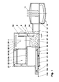
- Figur 1:
- Längsschnitt eines Elektrolichtbogenofens mit einem Chargierschacht-System;
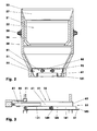
- Figur 2:
- Querschnitt des Chargierschacht-Systems;
- Figur 3:
- Schrott-Schubvorrichtung;
- Figur 4:
- Unteransicht der Schrott-Schubvorrichtung;
- Figur 5:
- Stirnansicht der Schrott-Schubvorrichtung;
- Figur 6:
- Ausgefahrene Schrott-Schubvorrichtung;
- Figur 7:
- Fühungsdetails der Schrott-Schubvorrichtung;
- Figur 8:
- Stirnplatte mit Nase;
- Figur 9:
- Detail des Chargierschacht-Systems mit Schrott-Schubvorrichtung und mit Schwenkklappe;
- Figur 10:
- Regelkreise der Schrott-Schubvorrichtung;
- Figur 11:
- Hydraulische Ansteuerung der Zylinder-Kolben-Einheiten.
- Die
Figuren 1 und2 zeigen einen Elektrolichtbogenofen (5) mit einem Ofengefäß (10) und mit einem Chargierschacht-System (20). Das Einsatzmaterial (4), z.B. Stahlschrott, wird mittels des Chargierschschacht-Systems (20) portionsweise dem Ofengefäß (10) zugeführt. Dort wird es mithilfe elektrischer und/oder fossiler Energie geschmolzen. Nach dem Schmelzen und Feinen bzw. Homogenisieren wird aus dem Ofengefäß (10) Flüssigstahl mit einer Temperatur von z.B. 1620 Grad Celsius abgestochen. Mit einer derartigen Anlage können pro Stunde mehr als 100 Tonnen Flüssigstahl aus Stahlschrott erzeugt werden. Aufgrund der geringen Dichte des Einsatzmaterials (4) - die Dichte von Schrott beträgt weniger als ein Zehntel der Dichte des Flüssigstahls - ist für die genannte Abstichmasse der Einsatz von mehr als 200 Kubikmeter Schrott erforderlich. - Das Chargierschacht-System (20) hat ein Traggerüst (21), das im Ausführungsbeispiel ein Vorchargierfach (22) mit einem Trichter (27) und mit einem Verschluss (23) sowie einen schachtförmigen Behälter (31) trägt. Das Vorchargierfach (22) und der schachtförmige Behälter (31) sind beispielsweise mittels einer öffenbaren Trennwand (24) voneinander abgegrenzt. Das Traggerüst (21) dient unter anderem der Wasserverteilung für die gekühlten Bereiche des an seiner Oberseite verschlossenen schachtförmigen Behälters (31). An einer oder an beiden Seitenwänden (32) des schachtförmigen Behälters (31) sind Absaugöffnungen (33) angeordnet. An den schachtförmigen Behälter grenzt in Richtung des Ofengefäßes (10) ein Absaugkanal (34) an. Letzterer hat in dem in der
Figur 1 dargestellten Längsschnitt z.B. eine Länge von 1,2 Metern. Seine Breite normal zur Zeichenebene derFigur 1 entspricht der Breite des schachtförmigen Behälters (31). - Der schachtförmige Behälter (31), der Absaugkanal (34) und das Ofengefäß (10) sind beispielsweise mittels eines Tunnels (35) verbunden. Dieser hat z.B. eine Länge von zwei Metern und einen beispielsweise rechteckigen Querschnitt. Seine Wände können wassergekühlt sein.
- Das gesamte Chargierschacht-System (20) ist beispielsweise um zwei Meter verfahrbar, um das Ofengefäß (10) entnehmen zu können.
- Die dem Absaugkanal (34) zugewandte Wand (36) des schachtförmigen Behälters (31) umfasst im Ausführungsbeispiel eine Schwenkklappe (41) vgl. die
Figuren 1 und9 . Diese wassergekühlte Klappe (41) hat im Ausführungsbeispiel eine Höhe von 500 Millimetern unterhalb der Schwenkachse (42). Ihre Breite entspricht der Innenbreite des schachtförmigen Behälters (31). Die gesamte Klappe (41) ist um die an der Außenseite des schachtförmigen Behälters (31) gelagerte Schwenkachse (42) beispielsweise um einen Winkel von 90 Grad schwenkbar. Dieser Winkel kann auch bis zu 110 Grad betragen. In der in derFigur 9 dargstellten Ausgangsposition (44) hängt die Schwenkklappe (41) unter dem Einfluß ihrer Schwerkraft zumindest annähernd vertikal, so dass ihre Unterkante (43) einen Abstand von z.B. 2100 Millimetern von der Bodenfläche (37) des schachtförmigen Behälters (31) hat. Die Unterkante (43) liegt dann z.B. 900 Millimeter oberhalb einer Schrott-Schubvorrichtung (51). In einer oder in beiden Endlagen kann die Schwenkklappe (41) beispielsweise durch außerhalb des schachtförmigen Behälters (31) angeordnete Anschläge am weiteren Schwenken gehindert sein. In dieser geschwenkten Position kann die Schwenkklappe (41) den Absaugkanal (34) z.B. bis zur Hälfte verdecken. Hiermit kann selbst bei einem Blockieren des Schrotts (4) der komplette Abgas-Volumenstrom durch den Absaugkanal (34) gesaugt werden. - Am unteren Abschnitt des schachtförmigen Behälters (31) ist die Schrott-Schubvorrichtung (51) angeordnet, vgl. die
Figuren 1 - 7 . Diese umfasst einen im Traggerüst (21) geführten Schrottschieber (52) sowie dessen Antriebssystem (81). - Der Schrottschieber (52) umfasst im Ausfühungsbeispiel einen ersten, äußeren Schiebeklotz (61) und einen in diesem geführten inneren Schubklotz (101). Der Schiebeklotz (61) ist ein Hohlkörper und hat eine zumindest annähernd trapezoidförmige Hüllkontur. Hierbei sind die kurzen Seiten unten angeordnet. Der beispielsweise als Schweißkonstruktion ausgeführte Schiebeklotz (61) ist symmetrisch zu einer vertikalen Mittenlängsebene aufgebaut. Seine Oberseite (62) und seine vordere Stirnfläche (63) sind als Planflächen ausgebildet. Die Seitenflächen (64) haben einen unteren geraden Bereich (65) und einen einachsig gewölbten Führungsbereich (66), vgl. die
Figuren 5 und7 . Der Krümmungsradius des Führungsbereichs (66) ist beispielsweise größer als 2 Meter. Der Führungsbereich (66) trägt zumindest abschnittsweise Gleitplatten (67), die im eingebauten Zustand an Gleitplatten (25) des Traggerüsts (21) anliegen. Die Gleitplatten (25, 67) dieser Linearführung (55) können aus Stahl oder aus einer verschleißfesten Metalllegierung hergestellt sein. Gegebenenfalls sind Kohlenstoffeinlagerungen zur Verringerung des Haft-und/oder Gleitreibungskoeffizienten denkbar. Weitere Gleitelemente (68) sind z.B. an der weitgehenden offenen Unterseite (69) angeordnet. - Die Stirnplatte (71) ist im Ausführungsbeispiel normal zu den Führungen (72) ausgebildet. Beispielsweise im Innenraum (73) des Schiebeklotzes (61) sind zwei Antriebseinheiten (82, 92), z.B. Zylinder-Kolben-Einheiten (82, 92), befestigt. Diese bilden das Antriebssystem (81) der Schrott-Schubvorrichtung (51). Die beiden zueinander parallel angeordneten identischen Zylinder-Kolben-Einheiten (82, 92) haben jeweils einen beispielsweise am Traggerüst (21) in einem Gelenklager (83) gelagerten Zylinder (84) und einen im Zylinder (84) geführten Kolben (85) mit einer Kolbenstange (86). Letztere ist mit einem Gelenklager (87) im Schiebeklotz (61) gelagert. Im Ausführungsbeispiel beträgt der Kolbenhub 6000 Millimeter, der Kolbendurchmesser 340 Millimeter und der Kolbenstangendurchmesser 240 Millimeter. Im eingebauten Zustand ist die Stirnplatte (71) des Schiebeklotzes (61) bündig mit der Innenwandung des schachtförmigen Behälters (31). Der Schrottschieber (52) ist beispielsweise waagerecht angeordnet, so dass er auf der horizontalen Bodenfläche (37) aufliegt.
- Die Stirnplatte (71) des Schiebeklotzes (61) hat eine Ausnehmung (74), aus der im eingebauten Zustand der Schubklotz (101) in der eingefahrenen Position z.B. um 300 Millimeter heraussteht. Die Stirnfläche (63) des Schiebeklotzes (61) kann auch bündig mit der Stirnfläche (103) des Schubklotzes (101) sein. Der Schubklotz (101) ist im Ausführungsbeispiel in seiner Hüllkontur quaderförmig ausgebildet. Die Schweißkonstruktion ist z.B. symmetrisch zu ihrer vertikalen Mittenlängsebene. Der als Hohlkörper ausgebildete Schrott-Schubklotz (101) trägt an seinen Längsseiten (102) Führungsprismen (104). Im eingebauten Zustand sitzen diese in komplementär ausgebildeten Führungsaufnahmen (75) des Schiebeklotzes (61). Die obere und die untere Führungsfläche (105) der Führungsprismen (104) schließen beispielsweise einen Winkel von 60 Grad ein. Das Führungssystem (75, 104) kann auch so ausgebildet sein wie das Führungssystem des Schiebeklotzes (61). Auch der Schiebeklotz (61) kann mittels einer Prismenführung z.B. im Traggerüst (21) geführt sein. Ebenfalls ist eine Rollenführung denkbar.
- Die Stirnplatte (106) des Schubklotzes (101) ist im Ausführungsbeispiel normal zu den Führungen (75, 104) angeordnet. Ihre Stirnfläche (103) beträgt 30 % der gesamten Schieberstirnfläche (53), die sich aus der Summe der Strinflächen (63, 103) des Schiebeklotzes (61) und des Schubklotzes (101) ergibt. Die Unterkanten der beiden Stirnflächen (63, 103) sind miteinander bündig, die Höhe der Schubklotz-Stirnfläche (103) beträgt in der Darstellung der
Figur 5 43 % der Schieberstirnfläche (53). - Die
Figur 8 zeigt eine Draufsicht eines Schubklotzes (101) mit einer nasenförmig ausgebildeten Stirnplatte (106). Die beiden die Nase (107) bildenden Flügel (108) schließen einen Winkel von 174 Grad ein. Dieser Winkel kann zwischen 150 Grad und 180 Grad liegen. Auch die Stirnplatte (71) des Schiebeklotzes (61) kann nasenförmig ausgebildet sein. Die Nase (107) ist im Ausführungsbeispiel vertikal angeordnet. - Beispielsweise an der Rückseite (109) des Schubklotzes (101) ist eine weitere als Zylinder-Kolben-Einheit (121) ausgebildete Antriebseinheit (121) angeordnet. Im Ausführungsbeispiel ist der Zylinder (124) dieser Zylinder-Kolben-Einheit (121) mittels eines Gelenklagers (123) am Schiebeklotz (61) gelagert. Die Kolbenstange (126) ist in einem Gelenklager (127) am Schubklotz (101) gelagert. Der Durchmesser des Kolbens (125) und der Durchmesser der Kolbenstange (126) sind im Ausführungsbeispiel gleich den Werten der ersten Antriebseinheiten (82, 92). Somit ist die wirksame Kolbenfläche (89) einer ersten Zylinder-Kolben-Einheit (82; 92) genauso groß wie die wirksame Kolbenfläche (122) der zweiten Zylinder-Kolben-Einheit (121). Der Kolbenhub ist halb so groß wie der Kolbenhub der ersten Zylinder-Kolben-Einheiten (82, 92). Dieser Hub der zweiten Zylinder-Kolben-Einheit (121) kann z.B. zwischen 40 % und 60 % des Hubs der ersten Zylinder-Kolben-Einheiten (82, 92) betragen.
- Alle genannten Zylinder-Kolben-Einheiten (82, 92, 121) verfügen im Ausführungsbeispiel über ein Wegmesssystem (131), vgl.
Figur 11 . Die Zylinder-Kolben-Einheiten (82, 92, 121) können entweder in der hier beschriebenen Rundbauart oder in Zugankerbauart ausgeführt sein. Anstatt der Gelenklager (83, 87, 123, 127) können gegebenenfalls Schwenklager eingesetzt werden. Auch eine einseitge Flanschmontage, ein Schwenkzapfen, etc. ist denkbar. - Die Hydraulikverbindung (132) zwischen der zweiten Zylinder-Kolben-Einheit (121) und dem Traggerüst (21) ist beispielsweise mit Schläuchen (133) ausgeführt. In dem in der
Figur 1 dargestellten Ausführungsbeispiel liegen diese Schläuche (133) in einer Schlauchführungskette (134). Die Schläuche (133) können jedoch auch hängend ausgebildet sein. - Die hydraulische Ansteuerung ist so ausgelegt, dass die ersten (82, 92) und die zweiten Antriebseinheiten (121) unabhängig voneinander angesteuert werden können. Das beispielsweise zentrale hydraulische Aggregat ermöglicht, alle Antriebsheinheiten gleichzeitig zu verfahren. Der hierzu erforderliche Volumenstrom kann entweder mittels Pumpen oder mitttels eines Druckspeichers zur Verfügung gestellt werden. Die maximale Verfahrgeschwindigkeit beträgt beispielsweise 150 Millimeter pro Sekunde. Die Verrohrung zwischen dem hydraulischen Ventilstand und den Zylinder-Kolben-Einheiten (82, 92, 121) ist beispielsweise mit Rohren und Schläuchen der Nennweite zwei Zoll ausgeführt. Das Hydraulikmedium ist z.B. eine schwer entflammbare Hydraulikflüssigkeit auf der Basis von Wasser-Glykol. Auch andere hydraulische Flüssigkeiten, beispielsweise Hydrauliköl auf Mineralölbasis, sind denkbar. Der Nenndruck der Hydraulikanlage beträgt z.B. 160 x 105 N/m2.
- Der Ventilstand (141) einer einzelnen doppelt wirkenden Zylinder-Kolben-Einheit (82; 92; 121) ist in der
Figur 11 dargestellt. Die beiden anderen Ventilstände sind analog hierzu aufgebaut. Die von den Pumpen kommende Druckleitung (142) ist an zwei hydraulisch vorgesteuerte 2/2-Wegeventile (151, 153) mit Federrückstellung angeschlossen. Das jeweilige Vorsteuerventil (152, 154) ist im Ausführungsbeispiel ein elektromagnetisches 4/2-Wegeventil mit Federrückstellung. Abgangsseitig ist an eines dieser Ventile (152) die Kolbenseite (143) und an das andere Ventil (153) die Kolbenstangenseite (144) angeschlossen. In jeder Zuführleitung (147, 148) ist im Ausführungsbeispel ventilstandsseitig ein Drucksensor (145, 146) angeordnet. Die Zuführleitungen (147, 148) haben Schläuche (164) zum Ausgleich von Bewegungen der Zylinder-Kolben-Einheiten (82, 92, 121) relativ zum Ventilstand (141) und zum Traggerüst (21). - An den Zuführleitungen (147, 148) ist jeweils ein mit der Tankleitung (149) verbundenes, hydraulisch vorgesteuertes 2/2-Wegeventil (155, 157) mit Federrückstellung angeschlossen. Die Vorsteuerventile (156, 158) können so aufgebaut sein wie oben beschrieben. Im Ausführungsbeispiel hat das kolbenstangenseitige Tankventil (157) ein weiteres 2/2-Vorsteuerventil (159).
- Die Tankleitung (149) und die kolbenseitige Zuführleitung (147) sind mittels einer Bypassleitung (161) verbunden. In dieser Bypassleitung (161) sitzen ein elektromagnmetisch betätigtes 4/2-Wegeventil (162) mit Federrückstellung und beispielsweise ein Rückschlagventil (163).
- Nach dem Entladen des Schrottkorbs in das Vorchargierfach (22) wird der Verschluß (23) verschlossen. Ein zunächst im Vorchargierfach (22) angeordneter Schubkorb (26) mit einem Antrieb (28) fördert den Schrott (4) weiter in den schachtförmigen Behälter (31), wobei die Trennwand (24) zeitweise geöffnet wird. In den
Figuren 1 und9 ist der mit Schrott (4) befüllte schachtförmige Behälter (31) dargestellt. Während des Betriebs des Elektrolichtbogenofens (5) wird zumindest ein Teil der beim Schmelzprozess entstehenden Abgase durch die Schrottsäule (6) hindurch zur Absaugöffnung (33) gesaugt. Die Abgase geben hierbei unter Abkühlung thermische Energie an den Schrott (4) ab, der dabei vorgewärmt wird. - Die Schrott-Schubvorrichtung (51) ist in der Ausgangsposition eingefahren. Der Schrottschieber (52) steht in der in den
Figuren 1 und3 dargestellten Ausgangsposition. Alle Zylinder-Kolben-Einheiten (82, 92, 121) sind eingefahren. - Um den Schrott (4) aus dem schachtförmigen Behälter (31) in das Ofengefäß (10) zu fördern, wird die Schrott-Schubvorrichtung (51) ausgefahren, vgl.
Figur 6 . Hierzu wird mittels der beiden Zylinder-Kolben-Einheiten (82, 92) der Schrottschieber (52) aus in derFigur 1 gezeigte Lage nach rechts verfahren. Der Schrott (4) wird durch den Tunnel (35) hindurch in Richtung des Ofengefäßes (10) verschoben. Hierbei rutscht der Schrott (4) über die Ausmauerung (12) in das Ofengefäß (10). - Beim Schieben des Schrotts (4) wird dieser gegen den unteren Bereich der Schwenkklappe (41) - unterhalb der Schwenkachse (42) - gedrückt. Die Schwenkklappe (41) wird aufgeschwenkt. Der Aufschwenkwinkel kann ein Teilwinkel des maximalen Aufschwenkwinkels sein. Die Schwenkklappe (41) kann aber auch bis an den Endlagenanschlag geschwenkt werden.
- Der Schrottschieber (52) kann beispielsweise bis zu einem Meter in den Tunnel (35) geschoben werden. Der relativ zum Schiebeklotz (61) verfahrbare Schubklotz (101) ist in Richtung der Ofenmitte bis zu 100 Millimeter über die Ausmauerung (12) verfahrbar. Aufgrund des langen Gesamthubes kann der Tunnel (35) länger als ein Meter sein.
- Ist eine der Stirnplatten (71; 106) oder sind beide Stirnplatten (71, 106) - wie in der
Figur 8 dargestellt - nasenförmig ausgebildet, kann der Schrott (4) im Ofengefäß (10) verstärkt in den Bereich außerhalb der Elektroden (11) geleitet werden. Hiermit kann die Gefahr von Elektrodenbrüchen beim Chargieren weiter vermindert werden. - Sobald der Schrott (4) in das Ofengefäß (10) verschoben ist, fährt der Schrottschieber (52) zurück in seine eingefahrene Ausgangslage. Die Schwenkklappe (41) kann beispielsweise schwerkraftgesteuert in ihre vertikale Lage zurückklappen.
- Der Widerstand des Schrotts (4) kann beim Veschieben schwanken. Dies führt in den hydraulischen Leitungen (132, 133, 147, 148) zum Ansteigen oder zum Sinken des hydraulischen Drucks. Zumindest der kolbenseitige Drucksensor (145) hat einen oberen Druckschwellenwert. Sobald der hydraulische Druck in der Zuführleitung (147) diesen Druckschwellenwert überschreitet, werden das kolbenseitige Vorsteuerventil (152) und das kolbenstangenseitige Vorsteuerventil (154) der zweiten Zylinder-Kolben-Einheit (121) angesteuert und damit die Wegeventile (151, 153) geöffnet. Das von der Druckleitung (142) zugeführte hydraulische Medium verschiebt den Schubklotz (101) in der Führungsrichtung (128) relativ zum Schiebeklotz (61). Aus dem Kolbenstangenraum (129) wird hydraulisches Fluid in den Tank verdrängt. Hierbei ist die spezifische Flächenpressung der normal zur Führungsrichtung (128) projizierten wirksamen Stirnfläche (103) des Schubklotzes (101) auf das einzelne Schrottelement um 60 % größer als die spezifische Flächenpressung der normal zur Schieberführungsrichtung (54) projizierten wirksamen Schieberstirnfläche (53). Aufgrund der höheren Kraft kann der bodennahe blockierende Schrott (4) in Richtung des Ofengefäßes (10) verschoben werden. Der darüberliegende Schrott (4) kann - nach dem Zurückfahren des Schubklotzes (101) - nach unten nachrutschen.
- Während des Ausfahrens des Schubklotzes (101) bleiben die hydraulischen Ventile (151, 153) der ersten Zylinder-Kolben-Einheiten (82, 92) z.B. weiterhin geöffnet. Der Schrottschieber (52) kann weiterhin in Richtung des Ofengefäßes (10) verfahern. Sobald der Druck in der hydraulischen Leitung unterhalb eines oberen Rückschaltwertes abfällt, werden die Ventile (151, 153, 155, 157) der zweiten Zylinder-Kolben-Einheit (121) umgeschaltet. Die zweite Zylinder-Kolben-Einheit (121) kann nun wieder einfahren, während der Schrottschieber (52) weiter ausfährt. Dieser Vorgang kann sich während des Hubs des Schrottschiebers (52) mehrfach wiederholen. Der Druckwert des oberen Schwellenwerts kann höher liegen als der Druckwert des Rückschaltwerts, so dass ein Aufschwingen des Systems durch zu häufiges Ein- und Ausschalten vermieden wird.
- Die
Figur 10 zeigt oberen Bereich diesen Regelkreis (171). Hierin bildet der Schrottschieber (52) die Regelstrecke (172). Der Drucksensor (145) der ersten Zylinder-Kolben-Einheit (82, 92) ist das Messglied (173), das das Steuerglied (174), die zweite Zylinder-Kolben-Einheit (121), anspricht. - Sobald der kolbenseitige Drucksensor (145) einen unteren Schwellenwert unterschreitet, wird die Kolbenstangenseite (144) durch Umschalten des 4/2-Wegeventils (162) hydraulisch mit der Kolbenseite (143) verbunden. Ein Rückschlagventil (163) in der Verbindungsleitung (161) verhindert, dass hydraulisches Fluid in Richtung der Kolbenstangenseite (144) strömt. Die über die Kolbenstange (144) übertragene Kraft ist jetzt nur noch abhängig vom Kolbenstangendurchmesser. Dementsprechend niedriger ist die spezifische Kraft der Schieberstirnfläche (53) auf den Schrott (4). Aufgrund des höheren Volumenstroms in den kolbenseitigen Zylinderraum (88) ist bei dieser Differenzdruckschaltung die Geschwindigkeit des Kolbens im Verhältnis der Kolbenfläche zur Kolbenstangenfläche erhöht.
- Bei wieder erhöhtem Widerstand des Schrotts (4) steigt der mittels des Drucksensors (145) ermittelte Druck des Antriebssystems (81) wieder an. Sobald der Druck einen unteren Rückschaltschwellenwert überschreitet, wird die Differenzdruckschaltung wieder ausgeschaltet. Die Zylinder-Kolben-Einheiten (82, 92) verfahren nun wieder mit den gesamten wirksamen Kolbenflächen (89).
- Im unteren Bereich der
Figur 10 ist dieser Regelkreis (181) dargestellt. Auch in diesem Regelkreis (181) ist der Schrottschieber (52) die Regelstrecke (182) und der Drucksensor (145) der ersten Zylinder-Kolben-Einheiten (82; 92) das Messglied (183). Das Steuerglied (184) bildet jeweils das Wegeventil (162) zum Ein- und Ausschalten der Differenzdruckschaltung. - An allen Zylinder-Kolben-Einheiten (82, 92, 121) kann auch kolbenstangenseitig ein Drucksensor (146) in einen Regelkreis eingebunden sein.
- Auch Kombinationen der verschiedenen Ausführungsbeispiele sind denkbar.
-
- 4
- Einsatzmaterial, Stahlschrott
- 5
- Elektrolichtbogenofen
- 6
- Schrottsäule
- 10
- Ofengefäß
- 11
- Elektroden
- 12
- Ausmauerung
- 20
- Chargierschacht-System
- 21
- Traggerüst
- 22
- Vorchargierfach
- 23
- Verschluss
- 24
- Trennwand
- 25
- Gleitplatten, Führungsteil
- 26
- Schubkorb
- 27
- Trichter
- 28
- Antrieb
- 31
- schachtförmiger Behälter
- 32
- Seitenwand
- 33
- Absaugöffnung
- 34
- Absaugkanal
- 35
- Tunnel
- 36
- Wand von (31)
- 37
- Bodenfläche
- 38
- Regelklappe
- 41
- Schwenkklappe
- 42
- Schwenkachse
- 43
- Unterkante
- 44
- Ausgangsposition
- 51
- Schrott-Schubvorrichtung
- 52
- Schrottschieber
- 53
- Schieberstirnfläche
- 54
- Schieberführungsrichtung
- 55
- Linearführung
- 61
- Schiebeklotz
- 62
- Oberseite
- 63
- Stirnfläche
- 64
- Seitenflächen
- 65
- geraden Bereich
- 66
- Führungsbereich
- 67
- Gleitplatten, Führungsteil
- 68
- Gleitelemente
- 69
- Unterseite
- 71
- Stirnplatte
- 72
- Führungen
- 73
- Innenseite
- 74
- Ausnehmung
- 75
- Führungsaufnahmen
- 81
- Antriebssystem
- 82
- Antriebseinheit, Zylinder-Kolben-Einheit
- 83
- Gelenklager
- 84
- Zylinder
- 85
- Kolben
- 86
- Kolbenstange
- 87
- Gelenklager
- 88
- kolbenseitiger Zylinderraum
- 89
- Kolbenfläche
- 92
- Antriebseinheit, Zylinder-Kolben-Einheit
- 101
- Schrott-Schubklotz, Schubklotz
- 102
- Längsseiten
- 103
- Stirnfläche, Schubklotz-Stirnfläche
- 104
- Führungsprismen, Führungsteil
- 105
- Führungsfläche, Führungsteil
- 106
- Stirnplatte
- 107
- Nase
- 108
- Flügel
- 109
- Rückseite
- 121
- Antriebseinheit, Zylinder-Kolben-Einheit
- 122
- Kolbenfläche
- 123
- Gelenklager
- 124
- Zylinder
- 125
- Kolben
- 126
- Kolbenstange
- 127
- Gelenklager
- 128
- Führungsrichtung
- 129
- Kolbenstangenraum
- 131
- Wegmeßsystem
- 132
- Hydraulikverbindung
- 133
- Schläuche
- 134
- Schlauchführungskette
- 141
- Ventilstand
- 142
- Druckleitung
- 143
- Kolbenseite
- 144
- Kolbenstangenseite
- 145
- Drucksensor, kolbenseitig
- 146
- Drucksensor, kolbenstangenseitig
- 147
- Zuführleitung kolbenseitig
- 148
- Zuführleitung, kolbenstangenseitig
- 149
- Tankleitung
- 151
- 2/2 Wegeventil, kolbenseitig
- 152
- Vorsteuerventil
- 153
- 2/2-Wegeventil, kolbenstangenseitig
- 154
- Vorsteuerventil
- 155
- 2/2-Wegeventil, kolbenseitig
- 156
- Vorsteuerventil
- 157
- 2/2-Wegeventil, kolbenstangenseitig
- 158
- Vorsteuerventil
- 159
- 2/2-Vorsteuerventil
- 161
- Bypassleitung
- 162
- 4/2-Wegeventil
- 163
- Rückschlagventil
- 164
- Schlauch
- 171
- Regelkreis
- 172
- Regelstrecke
- 173
- Meßglied
- 174
- Steuerglied, Stellglied
- 181
- Regelkreis
- 182
- Regelstrecke
- 183
- Meßglied
- 184
- Steuerglied, Stellglied
Claims (9)
- Schrott-Schubvorrichtung (51) mit einem in einer Linearführung (55) geführten Schrottschieber (52) und mit einem hydraulischen Antriebssystem (81), das mindestens eine Zylinder-Kolben-Einheit (82; 92) umfasst, wobei der Schrottschieber (52) mindestens eine normal zur Schieberführungsrichtung (54) projizierte wirksame Schieberstirnfläche (53) aufweist, dadurch gekennzeichnet,- dass der Schrottschieber (52) einen intern geführten Schrott-Schubklotz (101) umfasst, der mittels mindestens einer einen Kolben (125) umfassenden zweiten hydraulischen Zylinder-Kolben-Einheit (121) relativ zur erstgenannten Zylinder-Kolben-Einheit (82; 92) antreibbar ist,- dass dieser Schubklotz (101) eine normal zu seiner Führungsrichtung (128) projizierte wirksame Stirnfläche (103) umfasst und- dass der Quotient aus der wirksamen Kolbenfläche (122) aller zweiten Zylinder-Kolbeneinheiten (121) und der wirksamen Stirnfläche (103) größer ist als der Quotient der wirksamen Kolbenflächen (89) aller ersten Zylinder-Kolben-Einheiten (82; 92) und der wirksamen Schieberstirnfläche (53).
- Schrott-Schubvorrichtung (51) nach Anspruch 1, dadurch gekennzeichnet, dass der Schrott-Schubklotz (101) in einem Schiebeklotz (61) geführt ist.
- Schrott-Schubvorrichtung (51) nach Anspruch 1, dadurch gekennzeichnet, dass der Schrottschieber (52) mittels zweier Zylinder-Kolben-Einheiten (82, 92) antreibbar ist.
- Schrott-Schubvorrichtung (51) nach Anspruch 1, dadurch gekennzeichnet, dass die Größe der wirksame Kolbenfläche (89) einer ersten Zylinder-Kolben-Einheit (82; 92) der Größe der wirksamen Kolbenfläche (122) einer zweiten Zylinder-Kolben-Einheit (121) entspricht.
- Schrott-Schubvorrichtung (51) nach Anspruch 1, dadurch gekennzeichnet, dass der Betrag des Hubs des Schrott-Schubklotzes (101) mindestens 45 % des Betrags des Hubs des Schiebeklotzes (61) beträgt.
- Schrott-Schubvorrichtung (51) nach Anspruch 1, dadurch gekennzeichnet, dass die Stirnplatte (106) des Schrott-Schubklotzes (101) nasenförmig ausgebildet ist.
- Schrott-Schubvorrichtung (51) nach Anspruch 1, dadurch gekennzeichnet, dass die hydraulische Ansteuerung der Zylinder-Kolben-Einheiten (82, 92, 121) einen zuschaltbaren Regelkreis (171) umfasst, dessen Strecke (172) der Schrottschieber (52), dessen Stellglied (174) die zweite Zylinder-Kolben-Einheit (121) und dessen Meßglied ein Drucksensor (145) der ersten Zylinder-Kolben-Einheit (82, 92) ist.
- Schrott-Schubvorrichtung (51) nach Anspruch 1, dass zummindest die ersten Zylinder-Kolben-Einheiten (82, 92) mittels Differenzdruckschaltungen ansteuerbar sind.
- Chargierschacht-System (20) mit einem schachtförmigen Behälter (31) und mit einer Schrott-Schubvorrichtung (51) nach Anspruch 1, dadurch gekennzeichnet, dass eine der Schrott-Schubvorrichtung (51) abgewandte Wand (36) des schachtförmigen Behälters eine Schwenkklappe (41) mit Schwerkraftrückstellung umfasst, wobei der Hub des Schrottschiebers (52) die Ebene der rückgestellten Schwenkklappe (41) durchdringt.
Applications Claiming Priority (2)
| Application Number | Priority Date | Filing Date | Title |
|---|---|---|---|
| DE102010049238A DE102010049238A1 (de) | 2010-10-25 | 2010-10-25 | Schrott-Schubvorrichtung |
| PCT/DE2011/001877 WO2012055391A1 (de) | 2010-10-25 | 2011-10-24 | Schrott-schubvorrichtung |
Publications (2)
| Publication Number | Publication Date |
|---|---|
| EP2633253A1 EP2633253A1 (de) | 2013-09-04 |
| EP2633253B1 true EP2633253B1 (de) | 2015-08-12 |
Family
ID=45463129
Family Applications (1)
| Application Number | Title | Priority Date | Filing Date |
|---|---|---|---|
| EP11805382.6A Not-in-force EP2633253B1 (de) | 2010-10-25 | 2011-10-24 | Schrott-schubvorrichtung |
Country Status (7)
| Country | Link |
|---|---|
| US (1) | US8950572B2 (de) |
| EP (1) | EP2633253B1 (de) |
| KR (1) | KR20140012944A (de) |
| CN (1) | CN103189704B (de) |
| DE (1) | DE102010049238A1 (de) |
| RU (1) | RU2013124029A (de) |
| WO (1) | WO2012055391A1 (de) |
Families Citing this family (9)
| Publication number | Priority date | Publication date | Assignee | Title |
|---|---|---|---|---|
| EP2682700A1 (de) * | 2012-07-03 | 2014-01-08 | Steb S.r.l. | Stahlherstellungsanlage |
| DE102012014142B3 (de) * | 2012-07-18 | 2013-12-12 | Inteco Special Melting Technologies Gmbh | Schrottvorwärm- und Zuführsystem |
| CN103335525B (zh) * | 2013-07-02 | 2014-10-01 | 宁夏太阳镁业有限公司 | 一种球团装料机 |
| CA3060087C (en) * | 2017-04-24 | 2024-03-26 | Igus Gmbh | System for line monitoring in an energy chain |
| CN107717598A (zh) * | 2017-11-13 | 2018-02-23 | 中国科学院合肥物质科学研究院 | 一种热水器内胆废边自动下料装置 |
| CN108516663B (zh) * | 2018-04-23 | 2023-11-07 | 芜湖东旭光电科技有限公司 | 用于伸缩件的固定装置、推进装置和推进系统 |
| CN110626558B (zh) * | 2019-09-10 | 2024-07-16 | 合肥哈工龙延智能装备有限公司 | 一种全自动智能开封装码垛一体机 |
| CN117355715A (zh) * | 2023-08-17 | 2024-01-05 | 浙江海亮股份有限公司 | 一种用于炉具的自动加料装置 |
| US11971218B1 (en) | 2023-09-01 | 2024-04-30 | Zhejiang Hailiang Co., Ltd. | Automatic charging apparatus for a furnace |
Family Cites Families (18)
| Publication number | Priority date | Publication date | Assignee | Title |
|---|---|---|---|---|
| US3384007A (en) * | 1967-08-09 | 1968-05-21 | Compactor Corp | Waster compacting device |
| US3621775A (en) * | 1969-07-31 | 1971-11-23 | Waterbury Hydraulic & Pollutio | Compacting mechanism |
| US3802337A (en) * | 1971-10-06 | 1974-04-09 | Gen Compactor Of Quebec Ltd | Refuse compactor |
| US3734005A (en) * | 1972-01-19 | 1973-05-22 | R Vogel | Waste compacting apparatus |
| US3802336A (en) * | 1972-11-24 | 1974-04-09 | Carrier Corp | Refuse compacting device |
| US3855950A (en) * | 1973-10-10 | 1974-12-24 | Consumat Syst Inc | Automatic loading and ash removal system for incinerators |
| FR2498309B1 (fr) * | 1981-01-20 | 1986-04-11 | Clesid Sa | Four electrique destine a la fusion de ferrailles et alimente en continu |
| US4534301A (en) * | 1984-06-08 | 1985-08-13 | General Electric Company | Incinerator ash removal systems |
| US4714031A (en) * | 1987-01-05 | 1987-12-22 | Westinghouse Electric Corp. | Combustor feeding arrangement |
| JPH07190629A (ja) * | 1993-04-15 | 1995-07-28 | Ishikawajima Harima Heavy Ind Co Ltd | スクラップ原料予熱装入装置 |
| DE29503058U1 (de) | 1995-02-23 | 1995-04-20 | Max Aicher GmbH Entsorgungstechnik, 83404 Ainring | Vorrichtung zum Zusammenpressen einer Masse, insbesondere Müll |
| LU88807A1 (de) * | 1996-08-20 | 1998-02-24 | Wurth Paul Sa | Chargiergutvorwaermer |
| CN2562082Y (zh) * | 2002-08-08 | 2003-07-23 | 上海博士高环保设备工程有限公司 | 非均匀阶梯炉排焚烧炉 |
| DE10355549A1 (de) * | 2003-11-27 | 2005-06-23 | Intracon Gmbh | Chargiergutvorwärmer |
| JP2005233491A (ja) * | 2004-02-19 | 2005-09-02 | Fuji Electric Systems Co Ltd | 電気溶融炉 |
| CN100510529C (zh) * | 2007-07-18 | 2009-07-08 | 重庆科技学院 | 台阶烘干式垃圾推料装置 |
| DE102009016774A1 (de) * | 2009-04-07 | 2010-10-14 | Fuchs Technology Holding Ag | Chargiervorrichtung |
| JP4886875B2 (ja) * | 2010-03-26 | 2012-02-29 | スチールプランテック株式会社 | プッシャー |
-
2010
- 2010-10-25 DE DE102010049238A patent/DE102010049238A1/de not_active Withdrawn
-
2011
- 2011-10-24 EP EP11805382.6A patent/EP2633253B1/de not_active Not-in-force
- 2011-10-24 RU RU2013124029/02A patent/RU2013124029A/ru not_active Application Discontinuation
- 2011-10-24 WO PCT/DE2011/001877 patent/WO2012055391A1/de not_active Ceased
- 2011-10-24 CN CN201180051647.1A patent/CN103189704B/zh not_active Expired - Fee Related
- 2011-10-24 KR KR1020137010481A patent/KR20140012944A/ko not_active Withdrawn
-
2013
- 2013-04-21 US US13/867,096 patent/US8950572B2/en not_active Expired - Fee Related
Also Published As
| Publication number | Publication date |
|---|---|
| US20140138216A1 (en) | 2014-05-22 |
| RU2013124029A (ru) | 2014-12-10 |
| KR20140012944A (ko) | 2014-02-04 |
| US8950572B2 (en) | 2015-02-10 |
| CN103189704A (zh) | 2013-07-03 |
| EP2633253A1 (de) | 2013-09-04 |
| DE102010049238A1 (de) | 2012-04-26 |
| WO2012055391A1 (de) | 2012-05-03 |
| CN103189704B (zh) | 2015-08-12 |
Similar Documents
| Publication | Publication Date | Title |
|---|---|---|
| EP2633253A1 (de) | Schrott-schubvorrichtung | |
| EP0468363A1 (de) | Einrichtung zum Wechseln eines Giessrohres an einem metallurgischen Gefäss | |
| DE102015110113B4 (de) | Absperrschieber | |
| AT506190B1 (de) | Vorrichtung zum auswechselbaren anschliessen eines giessrohres an einen ausguss eines schmelzenbehälters | |
| DE2746265A1 (de) | Schieberventil fuer ein giessgefaess | |
| WO2014012655A2 (de) | Schrottvorwärm- und zuführsystem | |
| EP2801981B1 (de) | Transfervorrichtung für den Transfer von Brennelementen | |
| DE202010018096U1 (de) | Schrott-Schubvorrichtung | |
| EP2801980B1 (de) | Transfervorrichtung für den Transfer von Brennelementen | |
| DE102011119624A1 (de) | Fülleinrichtung für eine Packmaschine | |
| DE1949995A1 (de) | Zwischenbehaelter (Tundish) fuer Stranggiessanlagen | |
| DE3809545C2 (de) | Vorrichtung zur Steuerung von auf einem drehbaren Trichter einer Schachtofen-Beschickungsanlage angebrachten Hydraulikzylindern | |
| DE2146677A1 (de) | Verfahren und Vorrichtung zur Steuerung des Flussigkeitsstroms durch die Bodenausgußöffnung eines Gießgefäßes | |
| DE1289924B (de) | Atomkernreaktor mit Druckrohren | |
| DE102010047516A1 (de) | Chargiervorrichtung | |
| DE2626628C2 (de) | Bunker für körniges, rieselfähiges Material | |
| EP4090482A1 (de) | Schiebeverschluss für ein metallurgisches gefäss | |
| DE102015110875B4 (de) | Verschlussvorrichtung, insbesondere für einen Feuerraum oder Abgaskanal | |
| DE1961579C3 (de) | Umstellvorrichtung für eine regenerativ beheizte Verbund-Koksofenbatterie | |
| DE1284228B (de) | Hydraulische Betaetigungsvorrichtung fuer Klappen oder Schieber, insbesondere auf Tankerschiffen | |
| EP2801982A2 (de) | Transfervorrichtung für den Transfer von Brennelementen | |
| DE102011109860A1 (de) | Chargiervorrichtung mit auswechselbarem Bodenabschnitt | |
| DE202010018098U1 (de) | Chargierschacht-System | |
| DE1483157A1 (de) | Blasrohrreinigungsmaschine zum Durchbohren oder Durchstossen der Blasrohre eines Konverters | |
| DE2318165C3 (de) | Molchbare Abfüllarmatur |
Legal Events
| Date | Code | Title | Description |
|---|---|---|---|
| PUAI | Public reference made under article 153(3) epc to a published international application that has entered the european phase |
Free format text: ORIGINAL CODE: 0009012 |
|
| 17P | Request for examination filed |
Effective date: 20130510 |
|
| AK | Designated contracting states |
Kind code of ref document: A1 Designated state(s): AL AT BE BG CH CY CZ DE DK EE ES FI FR GB GR HR HU IE IS IT LI LT LU LV MC MK MT NL NO PL PT RO RS SE SI SK SM TR |
|
| DAX | Request for extension of the european patent (deleted) | ||
| GRAJ | Information related to disapproval of communication of intention to grant by the applicant or resumption of examination proceedings by the epo deleted |
Free format text: ORIGINAL CODE: EPIDOSDIGR1 |
|
| GRAP | Despatch of communication of intention to grant a patent |
Free format text: ORIGINAL CODE: EPIDOSNIGR1 |
|
| INTG | Intention to grant announced |
Effective date: 20150413 |
|
| GRAS | Grant fee paid |
Free format text: ORIGINAL CODE: EPIDOSNIGR3 |
|
| GRAA | (expected) grant |
Free format text: ORIGINAL CODE: 0009210 |
|
| AK | Designated contracting states |
Kind code of ref document: B1 Designated state(s): AL AT BE BG CH CY CZ DE DK EE ES FI FR GB GR HR HU IE IS IT LI LT LU LV MC MK MT NL NO PL PT RO RS SE SI SK SM TR |
|
| REG | Reference to a national code |
Ref country code: GB Ref legal event code: FG4D Free format text: NOT ENGLISH |
|
| REG | Reference to a national code |
Ref country code: CH Ref legal event code: EP |
|
| REG | Reference to a national code |
Ref country code: AT Ref legal event code: REF Ref document number: 742545 Country of ref document: AT Kind code of ref document: T Effective date: 20150815 |
|
| REG | Reference to a national code |
Ref country code: IE Ref legal event code: FG4D Free format text: LANGUAGE OF EP DOCUMENT: GERMAN |
|
| REG | Reference to a national code |
Ref country code: DE Ref legal event code: R096 Ref document number: 502011007604 Country of ref document: DE |
|
| REG | Reference to a national code |
Ref country code: LT Ref legal event code: MG4D |
|
| REG | Reference to a national code |
Ref country code: NL Ref legal event code: MP Effective date: 20150812 |
|
| PG25 | Lapsed in a contracting state [announced via postgrant information from national office to epo] |
Ref country code: NO Free format text: LAPSE BECAUSE OF FAILURE TO SUBMIT A TRANSLATION OF THE DESCRIPTION OR TO PAY THE FEE WITHIN THE PRESCRIBED TIME-LIMIT Effective date: 20151112 Ref country code: LV Free format text: LAPSE BECAUSE OF FAILURE TO SUBMIT A TRANSLATION OF THE DESCRIPTION OR TO PAY THE FEE WITHIN THE PRESCRIBED TIME-LIMIT Effective date: 20150812 Ref country code: FI Free format text: LAPSE BECAUSE OF FAILURE TO SUBMIT A TRANSLATION OF THE DESCRIPTION OR TO PAY THE FEE WITHIN THE PRESCRIBED TIME-LIMIT Effective date: 20150812 Ref country code: LT Free format text: LAPSE BECAUSE OF FAILURE TO SUBMIT A TRANSLATION OF THE DESCRIPTION OR TO PAY THE FEE WITHIN THE PRESCRIBED TIME-LIMIT Effective date: 20150812 Ref country code: GR Free format text: LAPSE BECAUSE OF FAILURE TO SUBMIT A TRANSLATION OF THE DESCRIPTION OR TO PAY THE FEE WITHIN THE PRESCRIBED TIME-LIMIT Effective date: 20151113 |
|
| PG25 | Lapsed in a contracting state [announced via postgrant information from national office to epo] |
Ref country code: PT Free format text: LAPSE BECAUSE OF FAILURE TO SUBMIT A TRANSLATION OF THE DESCRIPTION OR TO PAY THE FEE WITHIN THE PRESCRIBED TIME-LIMIT Effective date: 20151214 Ref country code: IS Free format text: LAPSE BECAUSE OF FAILURE TO SUBMIT A TRANSLATION OF THE DESCRIPTION OR TO PAY THE FEE WITHIN THE PRESCRIBED TIME-LIMIT Effective date: 20151212 Ref country code: RS Free format text: LAPSE BECAUSE OF FAILURE TO SUBMIT A TRANSLATION OF THE DESCRIPTION OR TO PAY THE FEE WITHIN THE PRESCRIBED TIME-LIMIT Effective date: 20150812 Ref country code: HR Free format text: LAPSE BECAUSE OF FAILURE TO SUBMIT A TRANSLATION OF THE DESCRIPTION OR TO PAY THE FEE WITHIN THE PRESCRIBED TIME-LIMIT Effective date: 20150812 Ref country code: SE Free format text: LAPSE BECAUSE OF FAILURE TO SUBMIT A TRANSLATION OF THE DESCRIPTION OR TO PAY THE FEE WITHIN THE PRESCRIBED TIME-LIMIT Effective date: 20150812 Ref country code: PL Free format text: LAPSE BECAUSE OF FAILURE TO SUBMIT A TRANSLATION OF THE DESCRIPTION OR TO PAY THE FEE WITHIN THE PRESCRIBED TIME-LIMIT Effective date: 20150812 Ref country code: ES Free format text: LAPSE BECAUSE OF FAILURE TO SUBMIT A TRANSLATION OF THE DESCRIPTION OR TO PAY THE FEE WITHIN THE PRESCRIBED TIME-LIMIT Effective date: 20150812 |
|
| PG25 | Lapsed in a contracting state [announced via postgrant information from national office to epo] |
Ref country code: NL Free format text: LAPSE BECAUSE OF FAILURE TO SUBMIT A TRANSLATION OF THE DESCRIPTION OR TO PAY THE FEE WITHIN THE PRESCRIBED TIME-LIMIT Effective date: 20150812 |
|
| PG25 | Lapsed in a contracting state [announced via postgrant information from national office to epo] |
Ref country code: DK Free format text: LAPSE BECAUSE OF FAILURE TO SUBMIT A TRANSLATION OF THE DESCRIPTION OR TO PAY THE FEE WITHIN THE PRESCRIBED TIME-LIMIT Effective date: 20150812 Ref country code: CZ Free format text: LAPSE BECAUSE OF FAILURE TO SUBMIT A TRANSLATION OF THE DESCRIPTION OR TO PAY THE FEE WITHIN THE PRESCRIBED TIME-LIMIT Effective date: 20150812 Ref country code: EE Free format text: LAPSE BECAUSE OF FAILURE TO SUBMIT A TRANSLATION OF THE DESCRIPTION OR TO PAY THE FEE WITHIN THE PRESCRIBED TIME-LIMIT Effective date: 20150812 Ref country code: SK Free format text: LAPSE BECAUSE OF FAILURE TO SUBMIT A TRANSLATION OF THE DESCRIPTION OR TO PAY THE FEE WITHIN THE PRESCRIBED TIME-LIMIT Effective date: 20150812 |
|
| REG | Reference to a national code |
Ref country code: DE Ref legal event code: R097 Ref document number: 502011007604 Country of ref document: DE |
|
| PG25 | Lapsed in a contracting state [announced via postgrant information from national office to epo] |
Ref country code: RO Free format text: LAPSE BECAUSE OF FAILURE TO SUBMIT A TRANSLATION OF THE DESCRIPTION OR TO PAY THE FEE WITHIN THE PRESCRIBED TIME-LIMIT Effective date: 20150812 Ref country code: LU Free format text: LAPSE BECAUSE OF FAILURE TO SUBMIT A TRANSLATION OF THE DESCRIPTION OR TO PAY THE FEE WITHIN THE PRESCRIBED TIME-LIMIT Effective date: 20151024 |
|
| REG | Reference to a national code |
Ref country code: CH Ref legal event code: PL |
|
| PLBE | No opposition filed within time limit |
Free format text: ORIGINAL CODE: 0009261 |
|
| STAA | Information on the status of an ep patent application or granted ep patent |
Free format text: STATUS: NO OPPOSITION FILED WITHIN TIME LIMIT |
|
| PG25 | Lapsed in a contracting state [announced via postgrant information from national office to epo] |
Ref country code: MC Free format text: LAPSE BECAUSE OF FAILURE TO SUBMIT A TRANSLATION OF THE DESCRIPTION OR TO PAY THE FEE WITHIN THE PRESCRIBED TIME-LIMIT Effective date: 20150812 |
|
| 26N | No opposition filed |
Effective date: 20160513 |
|
| GBPC | Gb: european patent ceased through non-payment of renewal fee |
Effective date: 20151112 |
|
| REG | Reference to a national code |
Ref country code: IE Ref legal event code: MM4A |
|
| PG25 | Lapsed in a contracting state [announced via postgrant information from national office to epo] |
Ref country code: CH Free format text: LAPSE BECAUSE OF NON-PAYMENT OF DUE FEES Effective date: 20151031 Ref country code: LI Free format text: LAPSE BECAUSE OF NON-PAYMENT OF DUE FEES Effective date: 20151031 |
|
| REG | Reference to a national code |
Ref country code: FR Ref legal event code: ST Effective date: 20160630 |
|
| PG25 | Lapsed in a contracting state [announced via postgrant information from national office to epo] |
Ref country code: FR Free format text: LAPSE BECAUSE OF NON-PAYMENT OF DUE FEES Effective date: 20151102 Ref country code: SI Free format text: LAPSE BECAUSE OF FAILURE TO SUBMIT A TRANSLATION OF THE DESCRIPTION OR TO PAY THE FEE WITHIN THE PRESCRIBED TIME-LIMIT Effective date: 20150812 |
|
| PG25 | Lapsed in a contracting state [announced via postgrant information from national office to epo] |
Ref country code: GB Free format text: LAPSE BECAUSE OF NON-PAYMENT OF DUE FEES Effective date: 20151112 Ref country code: IE Free format text: LAPSE BECAUSE OF NON-PAYMENT OF DUE FEES Effective date: 20151024 |
|
| REG | Reference to a national code |
Ref country code: DE Ref legal event code: R082 Ref document number: 502011007604 Country of ref document: DE Representative=s name: PATENT- UND RECHTSANWAELTE BEHRMANN WAGNER PAR, DE Ref country code: DE Ref legal event code: R082 Ref document number: 502011007604 Country of ref document: DE Representative=s name: PATENTANWAELTE BEHRMANN WAGNER PARTNERSCHAFTSG, DE |
|
| PG25 | Lapsed in a contracting state [announced via postgrant information from national office to epo] |
Ref country code: HU Free format text: LAPSE BECAUSE OF FAILURE TO SUBMIT A TRANSLATION OF THE DESCRIPTION OR TO PAY THE FEE WITHIN THE PRESCRIBED TIME-LIMIT; INVALID AB INITIO Effective date: 20111024 Ref country code: SM Free format text: LAPSE BECAUSE OF FAILURE TO SUBMIT A TRANSLATION OF THE DESCRIPTION OR TO PAY THE FEE WITHIN THE PRESCRIBED TIME-LIMIT Effective date: 20150812 Ref country code: BG Free format text: LAPSE BECAUSE OF FAILURE TO SUBMIT A TRANSLATION OF THE DESCRIPTION OR TO PAY THE FEE WITHIN THE PRESCRIBED TIME-LIMIT Effective date: 20150812 |
|
| PG25 | Lapsed in a contracting state [announced via postgrant information from national office to epo] |
Ref country code: CY Free format text: LAPSE BECAUSE OF FAILURE TO SUBMIT A TRANSLATION OF THE DESCRIPTION OR TO PAY THE FEE WITHIN THE PRESCRIBED TIME-LIMIT Effective date: 20150812 |
|
| PG25 | Lapsed in a contracting state [announced via postgrant information from national office to epo] |
Ref country code: BE Free format text: LAPSE BECAUSE OF NON-PAYMENT OF DUE FEES Effective date: 20151031 |
|
| PG25 | Lapsed in a contracting state [announced via postgrant information from national office to epo] |
Ref country code: MT Free format text: LAPSE BECAUSE OF FAILURE TO SUBMIT A TRANSLATION OF THE DESCRIPTION OR TO PAY THE FEE WITHIN THE PRESCRIBED TIME-LIMIT Effective date: 20150812 |
|
| PGFP | Annual fee paid to national office [announced via postgrant information from national office to epo] |
Ref country code: IT Payment date: 20171020 Year of fee payment: 7 Ref country code: AT Payment date: 20171018 Year of fee payment: 7 |
|
| PG25 | Lapsed in a contracting state [announced via postgrant information from national office to epo] |
Ref country code: MK Free format text: LAPSE BECAUSE OF FAILURE TO SUBMIT A TRANSLATION OF THE DESCRIPTION OR TO PAY THE FEE WITHIN THE PRESCRIBED TIME-LIMIT Effective date: 20150812 |
|
| PG25 | Lapsed in a contracting state [announced via postgrant information from national office to epo] |
Ref country code: AL Free format text: LAPSE BECAUSE OF FAILURE TO SUBMIT A TRANSLATION OF THE DESCRIPTION OR TO PAY THE FEE WITHIN THE PRESCRIBED TIME-LIMIT Effective date: 20150812 |
|
| PGFP | Annual fee paid to national office [announced via postgrant information from national office to epo] |
Ref country code: TR Payment date: 20181016 Year of fee payment: 8 |
|
| REG | Reference to a national code |
Ref country code: DE Ref legal event code: R082 Ref document number: 502011007604 Country of ref document: DE Representative=s name: PATENTANWAELTE BEHRMANN WAGNER PARTNERSCHAFTSG, DE Ref country code: DE Ref legal event code: R082 Ref document number: 502011007604 Country of ref document: DE Representative=s name: PATENT- UND RECHTSANWAELTE BEHRMANN WAGNER PAR, DE |
|
| REG | Reference to a national code |
Ref country code: AT Ref legal event code: MM01 Ref document number: 742545 Country of ref document: AT Kind code of ref document: T Effective date: 20181024 |
|
| PG25 | Lapsed in a contracting state [announced via postgrant information from national office to epo] |
Ref country code: IT Free format text: LAPSE BECAUSE OF NON-PAYMENT OF DUE FEES Effective date: 20181024 Ref country code: AT Free format text: LAPSE BECAUSE OF NON-PAYMENT OF DUE FEES Effective date: 20181024 |
|
| PGFP | Annual fee paid to national office [announced via postgrant information from national office to epo] |
Ref country code: DE Payment date: 20191009 Year of fee payment: 9 |
|
| REG | Reference to a national code |
Ref country code: DE Ref legal event code: R119 Ref document number: 502011007604 Country of ref document: DE |
|
| PG25 | Lapsed in a contracting state [announced via postgrant information from national office to epo] |
Ref country code: DE Free format text: LAPSE BECAUSE OF NON-PAYMENT OF DUE FEES Effective date: 20210501 |
|
| PG25 | Lapsed in a contracting state [announced via postgrant information from national office to epo] |
Ref country code: TR Free format text: LAPSE BECAUSE OF NON-PAYMENT OF DUE FEES Effective date: 20201024 |