EP2632765B1 - Arretiereinrichtung einer längsverstellvorrichtung eines kraftfahrzeugsitzes mit sperrstiften - Google Patents
Arretiereinrichtung einer längsverstellvorrichtung eines kraftfahrzeugsitzes mit sperrstiften Download PDFInfo
- Publication number
- EP2632765B1 EP2632765B1 EP11770456.9A EP11770456A EP2632765B1 EP 2632765 B1 EP2632765 B1 EP 2632765B1 EP 11770456 A EP11770456 A EP 11770456A EP 2632765 B1 EP2632765 B1 EP 2632765B1
- Authority
- EP
- European Patent Office
- Prior art keywords
- line
- locking
- locking device
- point
- pin axis
- Prior art date
- Legal status (The legal status is an assumption and is not a legal conclusion. Google has not performed a legal analysis and makes no representation as to the accuracy of the status listed.)
- Not-in-force
Links
Images


Classifications
-
- B—PERFORMING OPERATIONS; TRANSPORTING
- B60—VEHICLES IN GENERAL
- B60N—SEATS SPECIALLY ADAPTED FOR VEHICLES; VEHICLE PASSENGER ACCOMMODATION NOT OTHERWISE PROVIDED FOR
- B60N2/00—Seats specially adapted for vehicles; Arrangement or mounting of seats in vehicles
- B60N2/02—Seats specially adapted for vehicles; Arrangement or mounting of seats in vehicles the seat or part thereof being movable, e.g. adjustable
- B60N2/04—Seats specially adapted for vehicles; Arrangement or mounting of seats in vehicles the seat or part thereof being movable, e.g. adjustable the whole seat being movable
- B60N2/06—Seats specially adapted for vehicles; Arrangement or mounting of seats in vehicles the seat or part thereof being movable, e.g. adjustable the whole seat being movable slidable
- B60N2/08—Seats specially adapted for vehicles; Arrangement or mounting of seats in vehicles the seat or part thereof being movable, e.g. adjustable the whole seat being movable slidable characterised by the locking device
- B60N2/0806—Seats specially adapted for vehicles; Arrangement or mounting of seats in vehicles the seat or part thereof being movable, e.g. adjustable the whole seat being movable slidable characterised by the locking device with pin alignment systems, e.g. with at least one of a plurality of locking pins always aligned w.r.t. at least one of a plurality of pin-receiving elements
-
- B—PERFORMING OPERATIONS; TRANSPORTING
- B60—VEHICLES IN GENERAL
- B60N—SEATS SPECIALLY ADAPTED FOR VEHICLES; VEHICLE PASSENGER ACCOMMODATION NOT OTHERWISE PROVIDED FOR
- B60N2/00—Seats specially adapted for vehicles; Arrangement or mounting of seats in vehicles
- B60N2/02—Seats specially adapted for vehicles; Arrangement or mounting of seats in vehicles the seat or part thereof being movable, e.g. adjustable
- B60N2/04—Seats specially adapted for vehicles; Arrangement or mounting of seats in vehicles the seat or part thereof being movable, e.g. adjustable the whole seat being movable
- B60N2/06—Seats specially adapted for vehicles; Arrangement or mounting of seats in vehicles the seat or part thereof being movable, e.g. adjustable the whole seat being movable slidable
- B60N2/08—Seats specially adapted for vehicles; Arrangement or mounting of seats in vehicles the seat or part thereof being movable, e.g. adjustable the whole seat being movable slidable characterised by the locking device
- B60N2/0812—Location of the latch
- B60N2/0818—Location of the latch inside the rail
-
- B—PERFORMING OPERATIONS; TRANSPORTING
- B60—VEHICLES IN GENERAL
- B60N—SEATS SPECIALLY ADAPTED FOR VEHICLES; VEHICLE PASSENGER ACCOMMODATION NOT OTHERWISE PROVIDED FOR
- B60N2/00—Seats specially adapted for vehicles; Arrangement or mounting of seats in vehicles
- B60N2/02—Seats specially adapted for vehicles; Arrangement or mounting of seats in vehicles the seat or part thereof being movable, e.g. adjustable
- B60N2/04—Seats specially adapted for vehicles; Arrangement or mounting of seats in vehicles the seat or part thereof being movable, e.g. adjustable the whole seat being movable
- B60N2/06—Seats specially adapted for vehicles; Arrangement or mounting of seats in vehicles the seat or part thereof being movable, e.g. adjustable the whole seat being movable slidable
- B60N2/08—Seats specially adapted for vehicles; Arrangement or mounting of seats in vehicles the seat or part thereof being movable, e.g. adjustable the whole seat being movable slidable characterised by the locking device
- B60N2/0831—Movement of the latch
- B60N2/0862—Movement of the latch sliding
- B60N2/0875—Movement of the latch sliding in a vertical direction
-
- Y—GENERAL TAGGING OF NEW TECHNOLOGICAL DEVELOPMENTS; GENERAL TAGGING OF CROSS-SECTIONAL TECHNOLOGIES SPANNING OVER SEVERAL SECTIONS OF THE IPC; TECHNICAL SUBJECTS COVERED BY FORMER USPC CROSS-REFERENCE ART COLLECTIONS [XRACs] AND DIGESTS
- Y10—TECHNICAL SUBJECTS COVERED BY FORMER USPC
- Y10T—TECHNICAL SUBJECTS COVERED BY FORMER US CLASSIFICATION
- Y10T74/00—Machine element or mechanism
- Y10T74/20—Control lever and linkage systems
- Y10T74/20576—Elements
- Y10T74/20636—Detents
Definitions
- the invention relates to a locking device of a longitudinal adjustment device of a motor vehicle seat, comprising a) a latching strip, which has periodically arranged latching openings and latching webs and a bottom rail of the L Lucassverstellvorraum is assigned and b) a locking unit which is associated with a seat rail of L Lucassverstellvorraum and the at least two, each having a front portion with a front end, adjoining the front end, cooperating with the locking webs tapering region and an adjoining the tapering region of the shank with an upper end, wherein the tapering region itself seen in profile from an upper point B to a lower point A tapers and having a pin axis.
- Such a locking device is from the DE 10242825 A1 previously known. The state of the art is still on the DE 197 09 149 A1 and the DE 27 29 770 C2 directed. Such locking devices are also referred to as Mehrricharretier sootheen. They allow a secure engagement and a fine-pitched longitudinal adjustment.
- two locking pins are in contact with a respective adjacent detent web.
- the locking pins are with their rejuvenation area in contact with the detent web.
- the tapering portion is formed as a frusto-conical portion, it is located between the front portion and the shaft portion of the locking pins.
- a locking pin blocks only in one direction. The two locking pins lock in different displacement directions. The angle at which the tapering area is in contact with the detent web lies in the area of self-locking.
- This solution has the following advantage: the more a locking pin is moved out of a latching opening, the lower the angle with which the tapering region rests against the latching web. The lower the force component, which can push out the locking pin in the z-direction from the latching opening. Overall, an unwanted release of the locking pin from a detent opening is thus much better prevented than is the case in the prior art.
- the invention maintains the distance between the points A and B projected on the longitudinal direction of the rails. This preserves the range available for the clearance compensation.
- the angle with which the tapering region rests against the latching web should be below the angle of the self-locking of the materials used with certainty.
- the angle is less than 6 °, preferably less than 5 °. Based on the angle between the line AB and the pin axis, this means a still slightly smaller angle, for example below 4.5 °.
- the pin axis is typically placed at an angle of about 0.5 ° to the detent openings during a load. The detent openings are perpendicular to the catch bar.
- the line AB can be composed of at least two sections, preferably a plurality of sections. For example, it may be a traverse of two, three or more rectilinear sections. It can also be pieced together from non-rectilinear sections. Also mixed forms with at least one rectilinear section and at least one curved portion extending are possible. If the line AB is composed of sections, it is continuous but not continuously differentiable.
- the line AB runs continuously differentiable between the points A and B. It is formed in this case of a continuous curve.
- the slope of the line AB decreases continuously from the point A to the point B down.
- the line AB is monotonous. She has no turning point.
- the line AB is formed by a part of a circular arc, an ellipse, a parabola or the like.
- the rejuvenation area ensures that the lock is free of play.
- the locking pins each dive so deep into a detent opening until a play-free locking is achieved by two locking pins.
- a front area is essentially conditioned and / or necessary by the production method of the locking pin by way of cold deformation or the like. It has proven to be very advantageous for the front area to have a cylindrical portion. This is for example 0.5 to 2 mm in the direction of the pin axis measured long. Due to the cylindrical portion ultimately complete release of the locking pin is prevented by a locking bar.
- the locking pin is at least in the tapering rotationally symmetrical about the pin axis. Preferably, it is rotationally symmetrical overall.
- the locking device according to FIG. 1 for a longitudinal adjustment of a motor vehicle seat has a bottom rail 20 which forms a catch bar 22. This has periodically arranged latching openings 24, in each case between two latching openings 24 is a latching web 26.
- the Lssensverstellvorraum further has a seat rail 28, with a locking unit 30 is connected.
- the locking unit 30 has a pin guide 32. It also has three locking pins 34, which are identical. They protrude through guide holes in the pin guide 32 therethrough. The two outer locking pins 34 are in contact with a respective adjacent latching web 26 of the locking bar 22, the system is free of play.
- the middle locking pin 34 is inactive, it rests on a latching web 26.
- Each locking pin 34 is a Assigned spring (not shown), which pre-loads him in the position shown. The spring moves her respective locking pin 34 down.
- the locking pins 34 have a collar 36, the collar 36 forms the region of greatest diameter of the locking pin 34. Below the collar 36 of the three locking pins 34 is a flap 38. It serves to unlock all three locking pins 34 of the locking unit 30 together.
- the left lock pin 34 is located on the flap 38.
- the flap 38 rests on the pin guide 32. Further immersion in the detent opening 24 is the left locking pin 34 therefore not possible.
- the left lock pin 34 is in its lowest position.
- a right-handed rectangular coordinate system with the axes x, y and z is used.
- the z-axis extends parallel to a pin axis 40.
- the x-direction extends in the longitudinal direction of the two rails 20, 28 and thus parallel to the direction of displacement of the L jossverstellvorraum.
- the y-axis is perpendicular to the paper plane in FIG. 1 ,
- the locking pins 34 each have a front portion 42 which has a front end 44. At the top, a tapering region 46 adjoins the front region 42. This in turn is followed by a shaft region 47 upwards. All of the figures show a side or profile view of the locking pin 34.
- the profile of the tapering portion 46 has an upper point B and a lower point A.
- the point B is on a circular line with a locking pin 34, as is the point A. These circular lines are concentric and in the middle of the pin axis 40.
- the cylindrical portion 52 preferably has an axial length of 10 to 30%, preferably about 25%, of the axial length of the tapered portion 46.
- the points A and B are connected by a straight line 48.
- the boundary of the tapering region 46 is never outside of this straight line 48, but at least partially within, preferably completely within.
- the points A and B through a line AB 60 with each other connected.
- the profile of the locking pins 34 is limited in the tapering region 46 by the line AB.
- the embodiments of the FIGS. 3 to 5 are constructed so that the line AB 60 is always within the line 48.
- the line AB 60 can be understood as a generatrix, with a rotational movement about the pin axis 40, the actual shell shape of the tapering region 46 is achieved.
- the terms outside and inside are used in relation to the position to the pin axis 40.
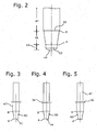
- the line AB 60 is not straight. In the embodiment according to FIG. 3 it runs on a circular arc. The center of the circular arc lies on a mid-perpendicular to the distance AB. In the embodiment according to FIG. 4 is the line AB 60 composed of two sections, each formed by circular arc pieces. There, where the two sections collide, results in a steady, but not steadily differentiable body. In the embodiment according to FIG. 5 the line AB is bounded by a section of an ellipse. The lines AB after the FIGS. 3 and 5 are constantly differentiable.
- the locking pins 34 after Fig. 1 and 2 which are carried out in the prior art, have a transition 50, which is located above the tapering portion 46 and is part of the shaft portion 47.
- This transition 50 has the shape of an axially very short truncated cone.
- the transition 50 is conditioned by production technology. It is advantageous to avoid such a transition 50.
- such a transition 50 is not provided in the shaft portion 47.
- the locking pin 34 can be formed without front region 42, in particular with only a very short front region 42.
- the front portion 42 can shrink in the axial direction practically to the length of more or less zero.
- the front end belongs to the front end 44.
- the constructive design is over FIG. 6 seen.
- the line AB 60 includes an angle 72 at point A with a parallel to the pin axis 40. This is the slope at point A.
- a tangent to line AB 60 includes an angle 70 with a line parallel to pin axis 40. This is the pitch angle at point B.
Description
- Die Erfindung bezieht sich auf eine Arretiereinrichtung einer Längsverstellvorrichtung eines Kraftfahrzeugsitzes, mit a) einer Rastenleiste, die periodisch angeordnete Rastöffnungen und Raststege aufweist und einer Bodenschiene der Längsverstellvorrichtung zugeordnet ist sowie b) einer Sperreinheit, die einer Sitzschiene der Längsverstellvorrichtung zugeordnet ist und die mindestens zwei, unabhängig von einander in Rastöffnungen einrastbare und gemeinsam ausrastbare Sperrstifte aufweist, welche jeweils einen Frontbereich mit einem Frontende, einen sich an das Frontende anschließenden, mit den Raststegen zusammenwirkenden Verjüngungsbereich und einen sich an den Verjüngungsbereich anschließenden Schaftbereich mit einem oberen Ende aufweisen, wobei der Verjüngungsbereich sich im Profil gesehen von einem oberen Punkt B zu einem unteren Punkt A verjüngt, und die eine Stiftachse haben.
- Eine derartige Arretiereinrichtung ist aus der
DE 10242825 A1 vorbekannt. Zum Stand der Technik wird weiterhin auch auf dieDE 197 09 149 A1 und dieDE 27 29 770 C2 verwiesen. Derartige Arretiereinrichtungen werden auch als Mehrstiftarretiereinrichtungen bezeichnet. Sie ermöglichen eine sicheres Einrasten und eine feinstufige Längsverstellung. In blockierter Stellung sind zwei Sperrstifte in Anlage an jeweils einem ihnen benachbarten Raststeg. Die Sperrstifte sind mit ihrem Verjüngungsbereich in Anlage am Raststeg. Der Verjüngungsbereich ist als kegelstumpfförmiger Bereich ausgebildet, er befindet sich zwischen dem Frontbereich und dem Schaftbereich der Sperrstifte. Ein Sperrstift sperrt jeweils nur in einer Verschieberichtung. Die beiden Sperrstifte sperren in unterschiedlichen Verschieberichtungen. Der Winkel, mit dem der Verjüngungsbereich in Anlage am Raststeg ist, liegt im Bereich der Selbsthemmung. - Da im allgemeinen nur ein Sperrstift für die Arretierung einer Verschieberichtung verantwortlich, ist, wirken auf diesen einen Sperrstift und auf den entsprechenden Raststeg, an dem der Sperrstift anliegt, während einer Belastung die gesamten Arretierungskräfte. Aufgrund der Belastung stellt sich der Sperrstift innerhalb seiner Führung in der Sperreinheit geringfügig schräg, was zu einer Vergrößerung des Winkels, mit dem der Verjüngungsbereich in Anlage am Raststeg ist, führt. Bei wiederholter Belastung, beispielsweise beim Überfahren mehrerer Bodenwellen oder bei Druck auf eine Rückenlehne des Kraftfahrzeugsitzes kommt es dazu, dass der für die Arretierung verantwortliche Sperrstift aus der Rastöffnung, in die er eingegriffenen hat, mehr oder weniger herausgedrückt wird, also in z-Richtung hochgedrückt wird. Dies ist nachteilig. Ein Herausdrücken führt zwar nicht zu einer vollständigen Freigabe der Arretierung, da mindestens noch ein weiterer Sperrstift in Eingriff in einer Rastöffnung ist und andere Sperrstifte nachrasten können, er führt aber zu einer gewissen Verstellung des Fahrzeugsitzes in Längsrichtung. Der Effekt kann sich mehrfach wiederholen.
- Es ist nachteilig, wenn ein Sperrstift aus der Arretierung heraus gedrückt wird. Die Kräfte, die den Sperrstift nach oben belasten, sollten möglichst klein sein. Es muss vermieden werden, dass der Sperrstift vom zugehörigen Raststeg freikommt.
- Hier setzt nun die Erfindung ein. Sie hat es sich zur Aufgabe gemacht, die Arretiereinrichtung der eingangs genannten Art dahingehend weiterzubilden, dass die Gefahr eines selbsttätigen, ungehinderten Hochdrückens eines Sperrstiftes verringert wird und insbesondere vermieden wird, dass ein Sperrstift ungewollt aus einer Rastöffnung freikommen kann.
- Diese Aufgabe wird gelöst durch eine Arretiereinrichtung mit den Merkmalen des Anspruchs 1.
- Bei dieser Arretiereinrichtung verläuft der Verjüngungsbereich nicht mehr kegelförmig. Anstelle des geradlinigen Verlaufs nach dem Stand der Technik zwischen den Punkten A und B hat der Sperrstift nun einen Verjüngungsbereich, der durch die nicht geradlinig verlaufende Linie AB beschrieben ist. Diese Linie liegt niemals außerhalb der Strecke AB. Sie liegt zumindest über einen Teilbereich innerhalb dieser Strecke. Der Winkel, mit dem der Verjüngungsbereich an einem Raststeg anliegt, ist nun nicht mehr konstant. Er ist abhängig von der Position des Sperrstiftes relativ zum Raststeg. In Nähe des Punktes A ist der Winkel kleiner als im Stand der Technik. Je näher die Anlage entlang der Linie AB dem Punkt B kommt, umso größer wird der Winkel zwischen dem Verjüngungsbereich und dem Raststeg. Der Winkel erreicht in Nähe des Punktes B Werte, die größer sind als im gradlinigen Verlauf nach dem Stand der Technik.
- Diese Lösung hat folgenden Vorteil: Je mehr ein Sperrstift aus einer Rastöffnung herausbewegt wird, umso geringer wird der Winkel, mit dem der Verjüngungsbereich am Raststeg anliegt. Umso geringer wird damit auch die Kraftkomponente, die den Sperrstift in z-Richtung aus der Rastöffnung herausdrücken kann. Insgesamt wird damit ein ungewolltes Freikommen des Raststiftes aus einer Rastöffnung deutlich besser verhindert, als dies im Stand der Technik der Fall ist.
- Die Erfindung behält den Abstand zwischen den Punkten A und B, projiziert auf die Längsrichtung der Schienen, bei. Damit wird der für den Spielausgleich zur Verfügung stehende Bereich beibehalten.
- In Nähe des Punktes A und insbesondere im unteren Drittel der Strecke AB soll der Winkel, mit dem der Verjüngungsbereich am Raststeg anliegt, mit Sicherheit unterhalb des Winkels der Selbsthemmung der verwendeten Materialien liegen. Beispielsweise liegt der Winkel unter 6°, vorzugsweise unter 5°. Bezogen auf den Winkel zwischen der Linie AB und der Stiftachse bedeutet dies einen noch etwas kleineren Winkel, beispielsweise unterhalb von 4,5°. Die Stiftachse stellt sich bei einer Belastung typischerweise in einen Winkel von etwa 0,5° zu den Rastöffnungen. Die Rastöffnungen liegen rechtwinklig zur Rastenleiste.
- Die Linie AB kann aus mindestens zwei Teilstücken, vorzugsweise mehreren Teilstücken zusammengesetzt sein. Sie kann beispielsweise ein Polygonzug von zwei, drei oder mehreren geradlinigen Teilstücken sein. Sie kann auch aus nicht gradlinig verlaufenden Teilstücken stückweise zusammengesetzt sein. Auch Mischformen mit mindestens einem geradlinigen Teilstück und mindestens einem gekrümmt verlaufenden Teilstück sind möglich. Wenn die Linie AB aus Teilstücken zusammengesetzt ist, ist sie stetig, aber nicht stetig differenzierbar.
- Vorteilhafterweise verläuft die Linie AB stetig differenzierbar zwischen den Punkten A und B. Sie ist in diesem Fall aus einer zusammenhängenden Kurve gebildet.
- Vorzugsweise nimmt die Steigung der Linie AB ausgehend vom Punkt A kontinuierlich zum Punkt B hin ab. Die Linie AB verläuft monoton. Sie hat keinen Wendepunkt. Vorzugsweise wird die Linie AB durch ein Teil eines Kreisbogens, einer Ellipse, einer Parabel oder dergleichen gebildet.
- Der Verjüngungsbereich sorgt dafür, dass die Arretierung spielfrei ist. Die Sperrstifte tauchen jeweils so tief in eine Rastöffnung ein, bis durch zwei Sperrstifte eine spielfreie Arretierung erreicht ist.
- Ein Frontbereich ist im Wesentlichen durch das Herstellungsverfahren des Sperrstiftes im Wege einer Kaltverformung oder dergleichen bedingt und/oder notwendig. Als sehr vorteilhaft hat es sich erwiesen, dass der Frontbereich einen zylindrischen Anteil aufweist. Dieser ist beispielsweise 0,5 bis 2 mm in Richtung der Stiftachse gemessen lang. Durch den zylindrischen Anteil wird letztendlich ein vollständiges Freikommen des Sperrstiftes von einem Raststeg verhindert.
- Vorzugsweise ist der Sperrstift zumindest im Verjüngungsbereich rotationssymmetrisch um die Stiftachse. Vorzugsweise ist er insgesamt rotationssymmetrisch.
- Der Schaftbereich ist für die Beschreibung der Erfindung nicht beachtlich. Er kann nach dem Stand der Technik ausgeführt sein. Im Schaftbereich sind üblicherweise Mittel, wie z.B. ein Kragen, vorgesehen, um einen Angriffspunkt für eine Klappe zu haben. Vorzugsweise befindet sich im Schaftbereich auch ein Rillenbereich, hierzu wird auf die Offenbarung der
DE 102 42 825 A1 verwiesen. Weitere Vorteile und Merkmale ergeben sich aus den sonstigen Ansprüchen sowie der folgenden Beschreibung von nicht einschränkend zu verstehenden Ausführungsbeispielen der Erfindung, die im Folgenden näher erläutert werden. In der Zeichnung zeigen: - Fig. 1:
- eine schnittbildliche Darstellung einer Arretiereinrichtung nach dem Stand der Technik, Schnittebene in der x-z-Ebene,
- Fig. 2:
- eine Ansicht mit Blickrichtung wie in
Figur 1 auf ein unteres Teilstücks eines Sperrstiftes nach dem Stand der Technik und ähnlich wie inFig. 1 , jedoch mit einem zylindrischen Anteil, - Fig. 3:
- eine Seitenansicht eines Sperrstiftes nach der Lehre des Patentanspruchs 1,
- Fig. 4:
- eine Seitenansicht wie
Fig. 3 für eine zweite Ausführung eines Sperrstiftes nach der Lehre des Anspruchs 1, - Fig. 5:
- eine Darstellung wie
Fig. 3 eines dritten Ausführungsbeispiels des Sperrstiftes nach der Lehre des Anspruchs 1, und - Fig. 6:
- eine vergrößerte Darstellung des rechten Teils eines unteren Teilstücks eines Sperrstiftes zur Erläuterung der Konstruktion und zum Vergleich mit einem Sperrstift nach dem Stand der Technik.
- Die Arretiereinrichtung nach
Figur 1 für eine Längsverstellung eines Kraftfahrzeugsitzes hat eine Bodenschiene 20, die eine Rastenleiste 22 ausbildet. Diese hat periodisch angeordnete Rastöffnungen 24, jeweils zwischen zwei Rastöffnungen 24 befindet sich ein Raststeg 26. Die Längsverstellvorrichtung hat weiterhin eine Sitzschiene 28, mit der eine Sperreinheit 30 verbunden ist. Die Sperreinheit 30 hat eine Stiftführung 32. Sie hat weiterhin drei Sperrstifte 34, die baugleich sind. Sie ragen durch Führungsbohrungen in der Stiftführung 32 hindurch. Die beiden äußeren Sperrstifte 34 sind in Anlage an jeweils einem ihnen benachbarten Raststeg 26 der Rastenleiste 22, die Anlage ist spielfrei. Der mittlere Sperrstift 34 ist inaktiv, er liegt auf einem Raststeg 26 auf. Jedem Sperrstift 34 ist eine (nicht dargestellte) Feder zugeordnet, die ihn in die gezeigte Position vorbelastet. Die Feder rückt ihren jeweiligen Sperrstift 34 nach unten. Die Sperrstifte 34 haben einen Kragen 36, der Kragen 36 bildet den Bereich größten Durchmessers des Sperrstiftes 34. Unterhalb der Kragen 36 der drei Sperrstifte 34 befindet sich eine Klappe 38. Sie dient dazu, alle drei Sperrstifte 34 der Sperreinheit 30 gemeinsam zu entriegeln. - Wie aus
Figur 1 zu ersehen ist, liegt der linke Sperrstift 34 auf der Klappe 38 auf. Die Klappe 38 liegt auf der Stiftführung 32 auf. Ein weiteres Eintauchen in die Rastöffnung 24 ist dem linken Sperrstift 34 daher nicht möglich. Der linke Sperrstift 34 ist in seiner tiefsten Position. - Für die Beschreibung wird ein rechtshändiges rechtwinkliges Koordinatensystem mit den Achsen x, y und z verwendet. Die z-Achse verläuft parallel zu einer Stiftachse 40. Die x-Richtung verläuft in Längsrichtung der beiden Schienen 20, 28 und damit parallel zur Verschieberichtung der Längsverstellvorrichtung. Die y-Achse verläuft rechtwinklig zur Papierebene in
Figur 1 . - Die Sperrstifte 34 haben jeweils einen Frontbereich 42, der ein Frontende 44 hat. Nach oben hin schließt sich an den Frontbereich 42 ein Verjüngungsbereich 46 an. An diesen wiederum schließt sich nach oben ein Schaftbereich 47 an. Alle Figuren zeigen eine Seiten- bzw. Profilansicht des Sperrstiftes 34. Das Profil des Verjüngungsbereichs 46 hat einen oberen Punkt B und einen unteren Punkt A. Der Punkt B liegt bei einem Sperrstift 34 auf einer Kreislinie, ebenso der Punkt A. Diese Kreislinien sind konzentrisch und mittig zur Stiftachse 40.
- In der Ausführung nach
Fig. 2 hat der Sperrstift 34 einen zylindrischen Anteil 52. Dieser ist Bestandteil des Frontbereichs 42. Der zylindrische Anteil 52 hat vorzugsweise eine axiale Länge von 10 bis 30%, vorzugsweise von etwa 25% der axialen Länge des Verjüngungsbereichs 46. - Bei dem Sperrstift 34 nach dem Stand der Technik sind die Punkte A und B durch eine Gerade 48 miteinander verbunden. Bei dem Sperrstift 34 mit den Merkmalen des Anspruchs 1 liegt die Begrenzung des Verjüngungsbereichs 46 nie außerhalb dieser Geraden 48, sondern zumindest teilweise innerhalb, vorzugsweise vollständig innerhalb. Die Punkte A und B durch eine Linie AB 60 miteinander verbunden. Das Profil der Sperrstifte 34 ist im Verjüngungsbereich 46 durch die Linie AB begrenzt. Die Ausführungsbeispiele nach den
Figuren 3 bis 5 sind so konstruiert, dass die Linie AB 60 stets innerhalb der Geraden 48 liegt. Die Linie AB 60 kann als eine Erzeugende verstanden werden, bei einer Drehbewegung um die Stiftachse 40 wird die tatsächliche Mantelform des Verjüngungsbereichs 46 erzielt. Die Begriffe außerhalb und innerhalb werden dabei in Bezug auf die Lage zur Stiftachse 40 benutzt. - Die Linie AB 60 verläuft nicht geradlinig. Im Ausführungsbeispiel nach
Figur 3 verläuft sie auf einem Kreisbogen. Der Mittelpunkt des Kreisbogens liegt auf einer Mittelsenkrechten zur Strecke AB. Im Ausführungsbeispiel nachFigur 4 ist die Linie AB 60 zusammengesetzt aus zwei Teilstücken, die jeweils durch Kreisbogenstücke gebildet sind. Dort, wo die beiden Teilstücke zusammenstoßen, ergibt sich eine stetige, aber nicht stetig differenzierbare Stelle. Im Ausführungsbeispiel nachFigur 5 wird die Linie AB durch ein Teilstück einer Ellipse begrenzt. Die Linien AB nach denFiguren 3 und 5 sind stetig differenzierbar. - Die Sperrstifte 34 nach
Fig. 1 und2 , die nach dem Stand der Technik ausgeführt sind, haben einen Übergang 50, der sich oberhalb des Verjüngungsbereichs 46 befindet und Teil des Schaftbereichs 47 ist. Dieser Übergang 50 hat die Form eines axial recht kurzen Stumpfkegels. Der Übergang 50 ist produktionstechnisch bedingt. Es ist vorteilhaft, einen derartigen Übergang 50 zu vermeiden. Bei der erfindungsgemäßen Ausgestaltung der Sperrstifte 34, sieheFiguren 3 bis 5 , ist ein derartiger Übergang 50 im Schaftbereich 47 nicht vorgesehen. - Es ist möglich, den Sperrstift 34 ohne Frontbereich 42, insbesondere mit einem nur sehr kurzen Frontbereich 42 auszubilden. Der Frontbereich 42 kann in axialer Richtung praktisch auf die Länge von mehr oder weniger Null schrumpfen. In jedem Fall gehört zum Frontbereich das Frontende 44.
- Die konstruktive Auslegung ist aus
Figur 6 ersichtlich. Die Linie AB 60 schließt im Punkt A mit einer Parallelen zur Stiftachse 40 einen Winkel 72 ein. Dies ist die Steigung im Punkt A. Im Punkt B schließt eine Tangente an die Linie AB 60 mit einer Parallelen zur Stiftachse 40 einen Winkel 70 ein. Dies ist der Steigungswinkel am Punkt B.
Claims (7)
- Arretiereinrichtung einer Längsverstellvorrichtung eines Kraftfahrzeugsitzes, mit a) einer Rastenleiste (22), die periodisch angeordnete Rastöffnungen (24) und Raststege (26) aufweist und einer Bodenschiene (20) der Längsverstellvorrichtung zugeordnet ist sowie b) einer Sperreinheit (30), die einer Sitzschiene (28) der Längsverstellvorrichtung zugeordnet ist und die mindestens zwei, unabhängig von einander in Rastöffnungen (24) einrastbare und gemeinsam ausrastbare Sperrstifte (34) aufweist, welche jeweils einen Frontbereich (42) mit einem Frontende (44), einen sich an das Frontende (44) anschließenden, mit den Raststegen (26) zusammenwirkenden Verjüngungsbereich (46) und einen sich an den Verjüngungsbereich (46) anschließenden Schaftbereich (47) mit einem oberen Ende aufweisen, wobei der Verjüngungsbereich (46) sich im Profil gesehen von einem oberen Punkt B zu einem unteren Punkt A verjüngt, und die eine Stiftachse (40) haben, dadurch gekennzeichnet, dass der Verjüngungsbereich (46) durch eine die Punkte A und B verbindende Linie (60) begrenzt ist, die keinen geradlinigen Verlauf hat, dass, gesehen von der Stiftachse (40), die Linie (60) nicht außerhalb einer Geraden (48) liegt, die die Punkte A und B verbindet, und dass, gesehen von der Stiftachse (40), die Linie (60) über mindestens ein Drittel der Strecke zwischen den Punkten A und B innerhalb der Geraden (48) liegt.
- Arretiereinrichtung nach Anspruch 1, dadurch gekennzeichnet, dass die Linie (60) im Punkt A einen Verlauf hat, der mit der Stiftachse (40)einen Winkel unter 5°, vorzugsweise unter 4° einschließt.
- Arretiereinrichtung nach einem der vorangegangenen Ansprüche, dadurch gekennzeichnet, dass die Linie (60) zumindest in ihrem oberen Drittel, ausgehend vom Punkt B, einen Verlauf hat, der mit der Stiftachse (40) einen Winkel grösser 7°, vorzugsweise kleiner 10° einschließt.
- Arretiereinrichtung nach einem der vorangegangenen Ansprüche, dadurch gekennzeichnet, dass die Linie (60) mindestens ein gradliniges Teilstück und/oder mindestens ein gekrümmt verlaufendes Teilstück aufweist.
- Arretiereinrichtung nach einem der vorangegangenen Ansprüche, dadurch gekennzeichnet, dass die Linie (60) zwischen den Punkten A und B stetig differenzierbar ist.
- Arretiervorrichtung nach einem der vorangegangenen Ansprüche, dadurch gekennzeichnet, dass die Steigung der Linie (60) kontinuierlich, insbesondere monoton verläuft und ausgehend vom Punkt A abnimmt, insbesondere stetig abnimmt.
- Arretiervorrichtung nach einem der vorangegangenen Ansprüche, dadurch gekennzeichnet, dass das Frontende (44) einen zylindrischen Ansatz (52) aufweist, der vorzugsweise 0,5 bis 2 mm lang ist.
Priority Applications (1)
| Application Number | Priority Date | Filing Date | Title |
|---|---|---|---|
| PL11770456T PL2632765T3 (pl) | 2010-10-27 | 2011-10-18 | Urządzenie unieruchamiające urządzenia do podłużnej regulacji fotela pojazdu mechanicznego z kołkami blokującymi |
Applications Claiming Priority (2)
| Application Number | Priority Date | Filing Date | Title |
|---|---|---|---|
| DE102010043025 | 2010-10-27 | ||
| PCT/EP2011/068146 WO2012055721A1 (de) | 2010-10-27 | 2011-10-18 | Arretiereinrichtung einer längsverstellvorrichtung eines kraftfahrzeugsitzes mit sperrstiften |
Publications (2)
| Publication Number | Publication Date |
|---|---|
| EP2632765A1 EP2632765A1 (de) | 2013-09-04 |
| EP2632765B1 true EP2632765B1 (de) | 2014-09-17 |
Family
ID=44802074
Family Applications (1)
| Application Number | Title | Priority Date | Filing Date |
|---|---|---|---|
| EP11770456.9A Not-in-force EP2632765B1 (de) | 2010-10-27 | 2011-10-18 | Arretiereinrichtung einer längsverstellvorrichtung eines kraftfahrzeugsitzes mit sperrstiften |
Country Status (5)
| Country | Link |
|---|---|
| US (1) | US8955813B2 (de) |
| EP (1) | EP2632765B1 (de) |
| CN (1) | CN103180169B (de) |
| PL (1) | PL2632765T3 (de) |
| WO (1) | WO2012055721A1 (de) |
Families Citing this family (7)
| Publication number | Priority date | Publication date | Assignee | Title |
|---|---|---|---|---|
| DE102013008871B4 (de) * | 2013-02-07 | 2022-05-19 | Keiper Seating Mechanisms Co., Ltd. | Verfahren, Verriegelungsvorrichtung und Fahrzeugsitz |
| DE102015221075B4 (de) * | 2015-10-28 | 2019-01-03 | Adient Luxembourg Holding S.À R.L. | Längseinsteller für einen fahrzeugsitz, fahrzeugsitz |
| CN111295308B (zh) * | 2017-09-06 | 2022-04-05 | 恺博座椅机械部件有限公司 | 用于纵向调节器的致动机构、用于车辆座椅的纵向调节器以及车辆座椅 |
| KR101908085B1 (ko) * | 2017-09-28 | 2018-10-15 | 주식회사 다스 | 차량용 시트레일의 록킹 장치 |
| KR101986137B1 (ko) * | 2017-10-31 | 2019-06-05 | 주식회사 다스 | 시트 레일의 록킹 장치 |
| IT201800006570A1 (it) * | 2018-06-21 | 2019-12-21 | Dispositivo di scorrimento per un sedile di veicolo provvisto di un sistema di bloccaggio migliorato | |
| JP7104971B2 (ja) * | 2018-08-08 | 2022-07-22 | デルタ工業株式会社 | スライド装置 |
Family Cites Families (16)
| Publication number | Priority date | Publication date | Assignee | Title |
|---|---|---|---|---|
| DE2729770C2 (de) | 1977-07-01 | 1982-03-18 | C. Rob. Hammerstein Gmbh, 5650 Solingen | Feststellvorrichtung für Gleitschienenführungen eines Fahrzeugsitzes |
| DE4330870C1 (de) * | 1993-09-11 | 1994-09-08 | Keiper Recaro Gmbh Co | Verriegelungssystem für verstellbare Fahrzeugsitze |
| WO1995017317A1 (de) | 1993-12-20 | 1995-06-29 | Keiper Recaro Gmbh & Co. | Verriegelungsvorrichtung für fahrzeugsitze, insbesondere kraftfahrzeugsitze |
| DE4400474C1 (de) * | 1994-01-11 | 1995-03-09 | Keiper Recaro Gmbh Co | Verriegelungsvorrichtung für Fahrzeugsitze, insbesondere Kraftfahrzeugsitze |
| DE4436221C1 (de) * | 1994-10-11 | 1996-02-22 | Keiper Recaro Gmbh Co | Verriegelungsvorrichtung für Fahrzeugsitze |
| DE19709149B4 (de) | 1997-03-06 | 2006-12-07 | C. Rob. Hammerstein Gmbh & Co. Kg | Mehrstiftarretiervorrichtung einer Längsverstellvorrichtung eines Kraftfahrzeugsitzes |
| DE19735030A1 (de) * | 1997-08-13 | 1999-02-25 | Keiper Gmbh & Co | Verriegelungsvorrichtung für Fahrzeugsitze, insbesondere Kraftfahrzeugsitze |
| DE50211631D1 (de) * | 2001-11-28 | 2008-03-20 | Hammerstein Gmbh C Rob | Arretiervorrichtung mit mehreren Sperrstiften |
| DE10262357B4 (de) | 2001-11-28 | 2018-07-12 | Adient Luxembourg Holding S.À R.L. | Arretiereinrichtung einer Längsverstellvorrichtung eines Kraftfahrzeugsitzes |
| EP1316465B2 (de) * | 2001-11-28 | 2014-06-04 | C.Rob. Hammerstein GmbH & Co.KG | Arretiervorrichtung mit gerillten Sperrstiften |
| US6869057B2 (en) * | 2002-12-20 | 2005-03-22 | Fuji Kiko Co., Ltd. | Seat slide device |
| WO2006053145A1 (en) * | 2004-11-12 | 2006-05-18 | Johnson Controls Technology Company | Vehicle seat track |
| US7905461B2 (en) * | 2005-05-19 | 2011-03-15 | Johnson Controls Technology Company | Seat track latch assembly |
| DE102007027321A1 (de) * | 2007-06-14 | 2009-02-05 | Brose Fahrzeugteile Gmbh & Co. Kommanditgesellschaft, Coburg | Verriegelungsvorrichtung für ein Schienenverstellsystem |
| DE112009003598B4 (de) * | 2008-12-18 | 2021-12-02 | Lear Corp. | Fahrzeugsitz-Schienenanordnung mit formschlüssigem Arretierungssystem |
| CN101607533B (zh) * | 2009-07-28 | 2011-08-10 | 宁波双林汽车部件股份有限公司 | 汽车座椅滑轨的内置式双柱销锁定装置 |
-
2011
- 2011-10-18 US US13/882,025 patent/US8955813B2/en not_active Expired - Fee Related
- 2011-10-18 CN CN201180051801.5A patent/CN103180169B/zh not_active Expired - Fee Related
- 2011-10-18 WO PCT/EP2011/068146 patent/WO2012055721A1/de active Application Filing
- 2011-10-18 PL PL11770456T patent/PL2632765T3/pl unknown
- 2011-10-18 EP EP11770456.9A patent/EP2632765B1/de not_active Not-in-force
Also Published As
| Publication number | Publication date |
|---|---|
| US8955813B2 (en) | 2015-02-17 |
| CN103180169A (zh) | 2013-06-26 |
| CN103180169B (zh) | 2015-12-02 |
| PL2632765T3 (pl) | 2015-02-27 |
| US20130299664A1 (en) | 2013-11-14 |
| EP2632765A1 (de) | 2013-09-04 |
| WO2012055721A1 (de) | 2012-05-03 |
Similar Documents
| Publication | Publication Date | Title |
|---|---|---|
| EP2632765B1 (de) | Arretiereinrichtung einer längsverstellvorrichtung eines kraftfahrzeugsitzes mit sperrstiften | |
| EP1316465B1 (de) | Arretiervorrichtung mit gerillten Sperrstiften | |
| EP1316466B1 (de) | Arretiervorrichtung mit mehreren Sperrstiften | |
| EP3529503B1 (de) | Befestiger zum sichern eines halteelements an einem träger und system umfassend einen befestiger und ein halteelement | |
| DE202005003626U1 (de) | Feststellvorrichtung für einen einstellbaren Fahrzeugsitz | |
| EP3586018B1 (de) | Befestigungsvorrichtung und befestigungsbaugruppe | |
| AT514070A4 (de) | Zahnradanordnung | |
| EP2997286B1 (de) | Kugelgewindetrieb | |
| DE102005005889B3 (de) | Rollenführung für ein Fahrzeugsitz-Schwingsystem mit Scherenführung | |
| EP3699385B1 (de) | Automatische türdichtung mit wenigstens einem haltemittel, wenigstens einem scherenmechanismus mit zwei scherenelementen und einer dichtungsleiste | |
| DE3715496A1 (de) | Zweiteiliges verbindungselement zum justierbaren verbinden zweier bauteile | |
| DE102012215418A1 (de) | Verriegelungsmechanismus | |
| EP3819513B1 (de) | Geitlager, ausstattungsvorrichtung mit wenigstens einem gleitlager und ausstattungsvorrichtung mit wenigstens einem drehbaren aufgenommenen lager | |
| DE10242825B4 (de) | Arretiervorrichtung mit gerillten Sperrstiften | |
| DE102017128522A1 (de) | Kugelgewindetrieb | |
| DE102018103227B4 (de) | Ventileinheit | |
| EP3927997A1 (de) | Kugelgewindetrieb mit verdrehsicherung | |
| DE102017201504A1 (de) | Feststellvorrichtung für einen einstellbaren Kraftfahrzeugsitz | |
| DE10262182B4 (de) | Arretiervorrichtung mit gerillten Sperrstiften | |
| DE102012015504B4 (de) | Bauteil mit Einschraubabschnitt und damit ausgestattete Baugruppe | |
| EP3720727B1 (de) | Vorrichtung für ein fahrzeugdach und verfahren zum betreiben einer vorrichtung für ein fahrzeugdach | |
| EP3999749B1 (de) | Folienlager | |
| DE102017129954A1 (de) | Befestigungssystem zur Befestigung eines Bauteils an einer Fahrzeugkarosserie | |
| EP2577072B1 (de) | Verbindungsanordnung | |
| DE102022210723A1 (de) | Feststellvorrichtung für einen einstellbaren Kraftfahrzeugsitz |
Legal Events
| Date | Code | Title | Description |
|---|---|---|---|
| PUAI | Public reference made under article 153(3) epc to a published international application that has entered the european phase |
Free format text: ORIGINAL CODE: 0009012 |
|
| 17P | Request for examination filed |
Effective date: 20130527 |
|
| AK | Designated contracting states |
Kind code of ref document: A1 Designated state(s): AL AT BE BG CH CY CZ DE DK EE ES FI FR GB GR HR HU IE IS IT LI LT LU LV MC MK MT NL NO PL PT RO RS SE SI SK SM TR |
|
| RIN1 | Information on inventor provided before grant (corrected) |
Inventor name: BENEKER, WILFRIED |
|
| DAX | Request for extension of the european patent (deleted) | ||
| GRAP | Despatch of communication of intention to grant a patent |
Free format text: ORIGINAL CODE: EPIDOSNIGR1 |
|
| INTG | Intention to grant announced |
Effective date: 20140522 |
|
| RAP1 | Party data changed (applicant data changed or rights of an application transferred) |
Owner name: JOHNSON CONTROLS METALS AND MECHANISMS GMBH & CO. |
|
| GRAS | Grant fee paid |
Free format text: ORIGINAL CODE: EPIDOSNIGR3 |
|
| GRAA | (expected) grant |
Free format text: ORIGINAL CODE: 0009210 |
|
| AK | Designated contracting states |
Kind code of ref document: B1 Designated state(s): AL AT BE BG CH CY CZ DE DK EE ES FI FR GB GR HR HU IE IS IT LI LT LU LV MC MK MT NL NO PL PT RO RS SE SI SK SM TR |
|
| REG | Reference to a national code |
Ref country code: GB Ref legal event code: FG4D Free format text: NOT ENGLISH |
|
| REG | Reference to a national code |
Ref country code: CH Ref legal event code: EP |
|
| REG | Reference to a national code |
Ref country code: IE Ref legal event code: FG4D Free format text: LANGUAGE OF EP DOCUMENT: GERMAN |
|
| REG | Reference to a national code |
Ref country code: AT Ref legal event code: REF Ref document number: 687517 Country of ref document: AT Kind code of ref document: T Effective date: 20141015 |
|
| REG | Reference to a national code |
Ref country code: DE Ref legal event code: R096 Ref document number: 502011004420 Country of ref document: DE Effective date: 20141030 |
|
| PG25 | Lapsed in a contracting state [announced via postgrant information from national office to epo] |
Ref country code: FI Free format text: LAPSE BECAUSE OF FAILURE TO SUBMIT A TRANSLATION OF THE DESCRIPTION OR TO PAY THE FEE WITHIN THE PRESCRIBED TIME-LIMIT Effective date: 20140917 Ref country code: GR Free format text: LAPSE BECAUSE OF FAILURE TO SUBMIT A TRANSLATION OF THE DESCRIPTION OR TO PAY THE FEE WITHIN THE PRESCRIBED TIME-LIMIT Effective date: 20141218 Ref country code: SE Free format text: LAPSE BECAUSE OF FAILURE TO SUBMIT A TRANSLATION OF THE DESCRIPTION OR TO PAY THE FEE WITHIN THE PRESCRIBED TIME-LIMIT Effective date: 20140917 Ref country code: NO Free format text: LAPSE BECAUSE OF FAILURE TO SUBMIT A TRANSLATION OF THE DESCRIPTION OR TO PAY THE FEE WITHIN THE PRESCRIBED TIME-LIMIT Effective date: 20141217 Ref country code: LT Free format text: LAPSE BECAUSE OF FAILURE TO SUBMIT A TRANSLATION OF THE DESCRIPTION OR TO PAY THE FEE WITHIN THE PRESCRIBED TIME-LIMIT Effective date: 20140917 |
|
| REG | Reference to a national code |
Ref country code: SK Ref legal event code: T3 Ref document number: E 17515 Country of ref document: SK |
|
| REG | Reference to a national code |
Ref country code: NL Ref legal event code: VDEP Effective date: 20140917 |
|
| REG | Reference to a national code |
Ref country code: LT Ref legal event code: MG4D |
|
| PG25 | Lapsed in a contracting state [announced via postgrant information from national office to epo] |
Ref country code: CY Free format text: LAPSE BECAUSE OF FAILURE TO SUBMIT A TRANSLATION OF THE DESCRIPTION OR TO PAY THE FEE WITHIN THE PRESCRIBED TIME-LIMIT Effective date: 20140917 Ref country code: LV Free format text: LAPSE BECAUSE OF FAILURE TO SUBMIT A TRANSLATION OF THE DESCRIPTION OR TO PAY THE FEE WITHIN THE PRESCRIBED TIME-LIMIT Effective date: 20140917 Ref country code: RS Free format text: LAPSE BECAUSE OF FAILURE TO SUBMIT A TRANSLATION OF THE DESCRIPTION OR TO PAY THE FEE WITHIN THE PRESCRIBED TIME-LIMIT Effective date: 20140917 Ref country code: HR Free format text: LAPSE BECAUSE OF FAILURE TO SUBMIT A TRANSLATION OF THE DESCRIPTION OR TO PAY THE FEE WITHIN THE PRESCRIBED TIME-LIMIT Effective date: 20140917 |
|
| REG | Reference to a national code |
Ref country code: PL Ref legal event code: T3 |
|
| PG25 | Lapsed in a contracting state [announced via postgrant information from national office to epo] |
Ref country code: NL Free format text: LAPSE BECAUSE OF FAILURE TO SUBMIT A TRANSLATION OF THE DESCRIPTION OR TO PAY THE FEE WITHIN THE PRESCRIBED TIME-LIMIT Effective date: 20140917 |
|
| PG25 | Lapsed in a contracting state [announced via postgrant information from national office to epo] |
Ref country code: PT Free format text: LAPSE BECAUSE OF FAILURE TO SUBMIT A TRANSLATION OF THE DESCRIPTION OR TO PAY THE FEE WITHIN THE PRESCRIBED TIME-LIMIT Effective date: 20150119 Ref country code: RO Free format text: LAPSE BECAUSE OF FAILURE TO SUBMIT A TRANSLATION OF THE DESCRIPTION OR TO PAY THE FEE WITHIN THE PRESCRIBED TIME-LIMIT Effective date: 20140917 Ref country code: ES Free format text: LAPSE BECAUSE OF FAILURE TO SUBMIT A TRANSLATION OF THE DESCRIPTION OR TO PAY THE FEE WITHIN THE PRESCRIBED TIME-LIMIT Effective date: 20140917 Ref country code: EE Free format text: LAPSE BECAUSE OF FAILURE TO SUBMIT A TRANSLATION OF THE DESCRIPTION OR TO PAY THE FEE WITHIN THE PRESCRIBED TIME-LIMIT Effective date: 20140917 Ref country code: IS Free format text: LAPSE BECAUSE OF FAILURE TO SUBMIT A TRANSLATION OF THE DESCRIPTION OR TO PAY THE FEE WITHIN THE PRESCRIBED TIME-LIMIT Effective date: 20150117 |
|
| REG | Reference to a national code |
Ref country code: CH Ref legal event code: PL |
|
| REG | Reference to a national code |
Ref country code: DE Ref legal event code: R097 Ref document number: 502011004420 Country of ref document: DE |
|
| PG25 | Lapsed in a contracting state [announced via postgrant information from national office to epo] |
Ref country code: MC Free format text: LAPSE BECAUSE OF FAILURE TO SUBMIT A TRANSLATION OF THE DESCRIPTION OR TO PAY THE FEE WITHIN THE PRESCRIBED TIME-LIMIT Effective date: 20140917 Ref country code: BE Free format text: LAPSE BECAUSE OF NON-PAYMENT OF DUE FEES Effective date: 20141031 |
|
| PLBE | No opposition filed within time limit |
Free format text: ORIGINAL CODE: 0009261 |
|
| STAA | Information on the status of an ep patent application or granted ep patent |
Free format text: STATUS: NO OPPOSITION FILED WITHIN TIME LIMIT |
|
| REG | Reference to a national code |
Ref country code: IE Ref legal event code: MM4A |
|
| PG25 | Lapsed in a contracting state [announced via postgrant information from national office to epo] |
Ref country code: LI Free format text: LAPSE BECAUSE OF NON-PAYMENT OF DUE FEES Effective date: 20141031 Ref country code: CH Free format text: LAPSE BECAUSE OF NON-PAYMENT OF DUE FEES Effective date: 20141031 Ref country code: DK Free format text: LAPSE BECAUSE OF FAILURE TO SUBMIT A TRANSLATION OF THE DESCRIPTION OR TO PAY THE FEE WITHIN THE PRESCRIBED TIME-LIMIT Effective date: 20140917 |
|
| 26N | No opposition filed |
Effective date: 20150618 |
|
| PG25 | Lapsed in a contracting state [announced via postgrant information from national office to epo] |
Ref country code: IT Free format text: LAPSE BECAUSE OF FAILURE TO SUBMIT A TRANSLATION OF THE DESCRIPTION OR TO PAY THE FEE WITHIN THE PRESCRIBED TIME-LIMIT Effective date: 20140917 |
|
| REG | Reference to a national code |
Ref country code: FR Ref legal event code: PLFP Year of fee payment: 5 |
|
| PG25 | Lapsed in a contracting state [announced via postgrant information from national office to epo] |
Ref country code: IE Free format text: LAPSE BECAUSE OF NON-PAYMENT OF DUE FEES Effective date: 20141018 |
|
| PG25 | Lapsed in a contracting state [announced via postgrant information from national office to epo] |
Ref country code: SI Free format text: LAPSE BECAUSE OF FAILURE TO SUBMIT A TRANSLATION OF THE DESCRIPTION OR TO PAY THE FEE WITHIN THE PRESCRIBED TIME-LIMIT Effective date: 20140917 |
|
| PG25 | Lapsed in a contracting state [announced via postgrant information from national office to epo] |
Ref country code: SM Free format text: LAPSE BECAUSE OF FAILURE TO SUBMIT A TRANSLATION OF THE DESCRIPTION OR TO PAY THE FEE WITHIN THE PRESCRIBED TIME-LIMIT Effective date: 20140917 |
|
| GBPC | Gb: european patent ceased through non-payment of renewal fee |
Effective date: 20151018 |
|
| PG25 | Lapsed in a contracting state [announced via postgrant information from national office to epo] |
Ref country code: BG Free format text: LAPSE BECAUSE OF FAILURE TO SUBMIT A TRANSLATION OF THE DESCRIPTION OR TO PAY THE FEE WITHIN THE PRESCRIBED TIME-LIMIT Effective date: 20140917 |
|
| PG25 | Lapsed in a contracting state [announced via postgrant information from national office to epo] |
Ref country code: LU Free format text: LAPSE BECAUSE OF NON-PAYMENT OF DUE FEES Effective date: 20141018 Ref country code: MT Free format text: LAPSE BECAUSE OF FAILURE TO SUBMIT A TRANSLATION OF THE DESCRIPTION OR TO PAY THE FEE WITHIN THE PRESCRIBED TIME-LIMIT Effective date: 20140917 Ref country code: HU Free format text: LAPSE BECAUSE OF FAILURE TO SUBMIT A TRANSLATION OF THE DESCRIPTION OR TO PAY THE FEE WITHIN THE PRESCRIBED TIME-LIMIT; INVALID AB INITIO Effective date: 20111018 Ref country code: GB Free format text: LAPSE BECAUSE OF NON-PAYMENT OF DUE FEES Effective date: 20151018 Ref country code: TR Free format text: LAPSE BECAUSE OF FAILURE TO SUBMIT A TRANSLATION OF THE DESCRIPTION OR TO PAY THE FEE WITHIN THE PRESCRIBED TIME-LIMIT Effective date: 20140917 |
|
| REG | Reference to a national code |
Ref country code: FR Ref legal event code: PLFP Year of fee payment: 6 |
|
| REG | Reference to a national code |
Ref country code: DE Ref legal event code: R081 Ref document number: 502011004420 Country of ref document: DE Owner name: ADIENT LUXEMBOURG HOLDING S.A.R.L., LU Free format text: FORMER OWNER: JOHNSON CONTROLS METALS AND MECHANISMS GMBH & CO. KG, 42699 SOLINGEN, DE Ref country code: DE Ref legal event code: R081 Ref document number: 502011004420 Country of ref document: DE Owner name: ADIENT LUXEMBOURG HOLDING S.A R.L., LU Free format text: FORMER OWNER: JOHNSON CONTROLS METALS AND MECHANISMS GMBH & CO. KG, 42699 SOLINGEN, DE |
|
| REG | Reference to a national code |
Ref country code: FR Ref legal event code: PLFP Year of fee payment: 7 |
|
| PGFP | Annual fee paid to national office [announced via postgrant information from national office to epo] |
Ref country code: CZ Payment date: 20170925 Year of fee payment: 7 |
|
| REG | Reference to a national code |
Ref country code: AT Ref legal event code: MM01 Ref document number: 687517 Country of ref document: AT Kind code of ref document: T Effective date: 20161018 |
|
| PG25 | Lapsed in a contracting state [announced via postgrant information from national office to epo] |
Ref country code: AT Free format text: LAPSE BECAUSE OF NON-PAYMENT OF DUE FEES Effective date: 20161018 |
|
| PGFP | Annual fee paid to national office [announced via postgrant information from national office to epo] |
Ref country code: DE Payment date: 20171031 Year of fee payment: 7 Ref country code: SK Payment date: 20171017 Year of fee payment: 7 Ref country code: FR Payment date: 20171024 Year of fee payment: 7 |
|
| PGFP | Annual fee paid to national office [announced via postgrant information from national office to epo] |
Ref country code: PL Payment date: 20171012 Year of fee payment: 7 |
|
| REG | Reference to a national code |
Ref country code: DE Ref legal event code: R081 Ref document number: 502011004420 Country of ref document: DE Owner name: ADIENT LUXEMBOURG HOLDING S.A R.L., LU Free format text: FORMER OWNER: ADIENT LUXEMBOURG HOLDING S.A.R.L., LUXEMBOURG, LU |
|
| PG25 | Lapsed in a contracting state [announced via postgrant information from national office to epo] |
Ref country code: MK Free format text: LAPSE BECAUSE OF FAILURE TO SUBMIT A TRANSLATION OF THE DESCRIPTION OR TO PAY THE FEE WITHIN THE PRESCRIBED TIME-LIMIT Effective date: 20140917 |
|
| PG25 | Lapsed in a contracting state [announced via postgrant information from national office to epo] |
Ref country code: AL Free format text: LAPSE BECAUSE OF FAILURE TO SUBMIT A TRANSLATION OF THE DESCRIPTION OR TO PAY THE FEE WITHIN THE PRESCRIBED TIME-LIMIT Effective date: 20140917 |
|
| REG | Reference to a national code |
Ref country code: DE Ref legal event code: R119 Ref document number: 502011004420 Country of ref document: DE |
|
| REG | Reference to a national code |
Ref country code: SK Ref legal event code: MM4A Ref document number: E 17515 Country of ref document: SK Effective date: 20181018 |
|
| PG25 | Lapsed in a contracting state [announced via postgrant information from national office to epo] |
Ref country code: CZ Free format text: LAPSE BECAUSE OF NON-PAYMENT OF DUE FEES Effective date: 20181018 Ref country code: DE Free format text: LAPSE BECAUSE OF NON-PAYMENT OF DUE FEES Effective date: 20190501 |
|
| PG25 | Lapsed in a contracting state [announced via postgrant information from national office to epo] |
Ref country code: FR Free format text: LAPSE BECAUSE OF NON-PAYMENT OF DUE FEES Effective date: 20181031 Ref country code: SK Free format text: LAPSE BECAUSE OF NON-PAYMENT OF DUE FEES Effective date: 20181018 |
|
| PG25 | Lapsed in a contracting state [announced via postgrant information from national office to epo] |
Ref country code: PL Free format text: LAPSE BECAUSE OF NON-PAYMENT OF DUE FEES Effective date: 20181018 |