EP2632517B1 - Dispositif d'injection - Google Patents
Dispositif d'injection Download PDFInfo
- Publication number
- EP2632517B1 EP2632517B1 EP11764253.8A EP11764253A EP2632517B1 EP 2632517 B1 EP2632517 B1 EP 2632517B1 EP 11764253 A EP11764253 A EP 11764253A EP 2632517 B1 EP2632517 B1 EP 2632517B1
- Authority
- EP
- European Patent Office
- Prior art keywords
- plunger
- latch
- syringe
- injection device
- housing
- Prior art date
- Legal status (The legal status is an assumption and is not a legal conclusion. Google has not performed a legal analysis and makes no representation as to the accuracy of the status listed.)
- Not-in-force
Links
Images


Classifications
-
- A—HUMAN NECESSITIES
- A61—MEDICAL OR VETERINARY SCIENCE; HYGIENE
- A61M—DEVICES FOR INTRODUCING MEDIA INTO, OR ONTO, THE BODY; DEVICES FOR TRANSDUCING BODY MEDIA OR FOR TAKING MEDIA FROM THE BODY; DEVICES FOR PRODUCING OR ENDING SLEEP OR STUPOR
- A61M5/00—Devices for bringing media into the body in a subcutaneous, intra-vascular or intramuscular way; Accessories therefor, e.g. filling or cleaning devices, arm-rests
- A61M5/178—Syringes
- A61M5/31—Details
- A61M5/32—Needles; Details of needles pertaining to their connection with syringe or hub; Accessories for bringing the needle into, or holding the needle on, the body; Devices for protection of needles
- A61M5/3205—Apparatus for removing or disposing of used needles or syringes, e.g. containers; Means for protection against accidental injuries from used needles
- A61M5/321—Means for protection against accidental injuries by used needles
-
- A—HUMAN NECESSITIES
- A61—MEDICAL OR VETERINARY SCIENCE; HYGIENE
- A61M—DEVICES FOR INTRODUCING MEDIA INTO, OR ONTO, THE BODY; DEVICES FOR TRANSDUCING BODY MEDIA OR FOR TAKING MEDIA FROM THE BODY; DEVICES FOR PRODUCING OR ENDING SLEEP OR STUPOR
- A61M5/00—Devices for bringing media into the body in a subcutaneous, intra-vascular or intramuscular way; Accessories therefor, e.g. filling or cleaning devices, arm-rests
- A61M5/178—Syringes
- A61M5/20—Automatic syringes, e.g. with automatically actuated piston rod, with automatic needle injection, filling automatically
- A61M5/2033—Spring-loaded one-shot injectors with or without automatic needle insertion
-
- A—HUMAN NECESSITIES
- A61—MEDICAL OR VETERINARY SCIENCE; HYGIENE
- A61M—DEVICES FOR INTRODUCING MEDIA INTO, OR ONTO, THE BODY; DEVICES FOR TRANSDUCING BODY MEDIA OR FOR TAKING MEDIA FROM THE BODY; DEVICES FOR PRODUCING OR ENDING SLEEP OR STUPOR
- A61M5/00—Devices for bringing media into the body in a subcutaneous, intra-vascular or intramuscular way; Accessories therefor, e.g. filling or cleaning devices, arm-rests
- A61M5/178—Syringes
- A61M5/20—Automatic syringes, e.g. with automatically actuated piston rod, with automatic needle injection, filling automatically
-
- A—HUMAN NECESSITIES
- A61—MEDICAL OR VETERINARY SCIENCE; HYGIENE
- A61M—DEVICES FOR INTRODUCING MEDIA INTO, OR ONTO, THE BODY; DEVICES FOR TRANSDUCING BODY MEDIA OR FOR TAKING MEDIA FROM THE BODY; DEVICES FOR PRODUCING OR ENDING SLEEP OR STUPOR
- A61M5/00—Devices for bringing media into the body in a subcutaneous, intra-vascular or intramuscular way; Accessories therefor, e.g. filling or cleaning devices, arm-rests
- A61M5/178—Syringes
- A61M5/31—Details
- A61M5/315—Pistons; Piston-rods; Guiding, blocking or restricting the movement of the rod or piston; Appliances on the rod for facilitating dosing ; Dosing mechanisms
- A61M5/31501—Means for blocking or restricting the movement of the rod or piston
-
- A—HUMAN NECESSITIES
- A61—MEDICAL OR VETERINARY SCIENCE; HYGIENE
- A61M—DEVICES FOR INTRODUCING MEDIA INTO, OR ONTO, THE BODY; DEVICES FOR TRANSDUCING BODY MEDIA OR FOR TAKING MEDIA FROM THE BODY; DEVICES FOR PRODUCING OR ENDING SLEEP OR STUPOR
- A61M5/00—Devices for bringing media into the body in a subcutaneous, intra-vascular or intramuscular way; Accessories therefor, e.g. filling or cleaning devices, arm-rests
- A61M5/178—Syringes
- A61M5/31—Details
- A61M5/315—Pistons; Piston-rods; Guiding, blocking or restricting the movement of the rod or piston; Appliances on the rod for facilitating dosing ; Dosing mechanisms
- A61M5/31511—Piston or piston-rod constructions, e.g. connection of piston with piston-rod
-
- A—HUMAN NECESSITIES
- A61—MEDICAL OR VETERINARY SCIENCE; HYGIENE
- A61M—DEVICES FOR INTRODUCING MEDIA INTO, OR ONTO, THE BODY; DEVICES FOR TRANSDUCING BODY MEDIA OR FOR TAKING MEDIA FROM THE BODY; DEVICES FOR PRODUCING OR ENDING SLEEP OR STUPOR
- A61M5/00—Devices for bringing media into the body in a subcutaneous, intra-vascular or intramuscular way; Accessories therefor, e.g. filling or cleaning devices, arm-rests
- A61M5/178—Syringes
- A61M5/31—Details
- A61M5/32—Needles; Details of needles pertaining to their connection with syringe or hub; Accessories for bringing the needle into, or holding the needle on, the body; Devices for protection of needles
- A61M5/3205—Apparatus for removing or disposing of used needles or syringes, e.g. containers; Means for protection against accidental injuries from used needles
- A61M5/321—Means for protection against accidental injuries by used needles
- A61M5/3243—Means for protection against accidental injuries by used needles being axially-extensible, e.g. protective sleeves coaxially slidable on the syringe barrel
- A61M5/326—Fully automatic sleeve extension, i.e. in which triggering of the sleeve does not require a deliberate action by the user
-
- A—HUMAN NECESSITIES
- A61—MEDICAL OR VETERINARY SCIENCE; HYGIENE
- A61M—DEVICES FOR INTRODUCING MEDIA INTO, OR ONTO, THE BODY; DEVICES FOR TRANSDUCING BODY MEDIA OR FOR TAKING MEDIA FROM THE BODY; DEVICES FOR PRODUCING OR ENDING SLEEP OR STUPOR
- A61M5/00—Devices for bringing media into the body in a subcutaneous, intra-vascular or intramuscular way; Accessories therefor, e.g. filling or cleaning devices, arm-rests
- A61M5/178—Syringes
- A61M5/20—Automatic syringes, e.g. with automatically actuated piston rod, with automatic needle injection, filling automatically
- A61M2005/206—With automatic needle insertion
-
- A—HUMAN NECESSITIES
- A61—MEDICAL OR VETERINARY SCIENCE; HYGIENE
- A61M—DEVICES FOR INTRODUCING MEDIA INTO, OR ONTO, THE BODY; DEVICES FOR TRANSDUCING BODY MEDIA OR FOR TAKING MEDIA FROM THE BODY; DEVICES FOR PRODUCING OR ENDING SLEEP OR STUPOR
- A61M5/00—Devices for bringing media into the body in a subcutaneous, intra-vascular or intramuscular way; Accessories therefor, e.g. filling or cleaning devices, arm-rests
- A61M5/178—Syringes
- A61M5/20—Automatic syringes, e.g. with automatically actuated piston rod, with automatic needle injection, filling automatically
- A61M2005/2073—Automatic syringes, e.g. with automatically actuated piston rod, with automatic needle injection, filling automatically preventing premature release, e.g. by making use of a safety lock
-
- A—HUMAN NECESSITIES
- A61—MEDICAL OR VETERINARY SCIENCE; HYGIENE
- A61M—DEVICES FOR INTRODUCING MEDIA INTO, OR ONTO, THE BODY; DEVICES FOR TRANSDUCING BODY MEDIA OR FOR TAKING MEDIA FROM THE BODY; DEVICES FOR PRODUCING OR ENDING SLEEP OR STUPOR
- A61M5/00—Devices for bringing media into the body in a subcutaneous, intra-vascular or intramuscular way; Accessories therefor, e.g. filling or cleaning devices, arm-rests
- A61M5/178—Syringes
- A61M5/31—Details
- A61M5/32—Needles; Details of needles pertaining to their connection with syringe or hub; Accessories for bringing the needle into, or holding the needle on, the body; Devices for protection of needles
- A61M5/3205—Apparatus for removing or disposing of used needles or syringes, e.g. containers; Means for protection against accidental injuries from used needles
- A61M5/321—Means for protection against accidental injuries by used needles
- A61M5/3243—Means for protection against accidental injuries by used needles being axially-extensible, e.g. protective sleeves coaxially slidable on the syringe barrel
- A61M5/3245—Constructional features thereof, e.g. to improve manipulation or functioning
- A61M2005/3247—Means to impede repositioning of protection sleeve from needle covering to needle uncovering position
-
- A—HUMAN NECESSITIES
- A61—MEDICAL OR VETERINARY SCIENCE; HYGIENE
- A61M—DEVICES FOR INTRODUCING MEDIA INTO, OR ONTO, THE BODY; DEVICES FOR TRANSDUCING BODY MEDIA OR FOR TAKING MEDIA FROM THE BODY; DEVICES FOR PRODUCING OR ENDING SLEEP OR STUPOR
- A61M2205/00—General characteristics of the apparatus
- A61M2205/35—Communication
- A61M2205/3507—Communication with implanted devices, e.g. external control
- A61M2205/3515—Communication with implanted devices, e.g. external control using magnetic means
-
- A—HUMAN NECESSITIES
- A61—MEDICAL OR VETERINARY SCIENCE; HYGIENE
- A61M—DEVICES FOR INTRODUCING MEDIA INTO, OR ONTO, THE BODY; DEVICES FOR TRANSDUCING BODY MEDIA OR FOR TAKING MEDIA FROM THE BODY; DEVICES FOR PRODUCING OR ENDING SLEEP OR STUPOR
- A61M5/00—Devices for bringing media into the body in a subcutaneous, intra-vascular or intramuscular way; Accessories therefor, e.g. filling or cleaning devices, arm-rests
- A61M5/178—Syringes
- A61M5/31—Details
- A61M5/32—Needles; Details of needles pertaining to their connection with syringe or hub; Accessories for bringing the needle into, or holding the needle on, the body; Devices for protection of needles
- A61M5/3202—Devices for protection of the needle before use, e.g. caps
- A61M5/3204—Needle cap remover, i.e. devices to dislodge protection cover from needle or needle hub, e.g. deshielding devices
Definitions
- This invention relates to injection devices and in particular, but not exclusively, to injection devices of the type where a syringe is disposed in an elongate housing and a shroud element moves forwardly relative to the syringe after use to shroud the needle and thereby minimise the risk of accidental needle stick injuries.
- a medical injection device including a shield system and a syringe coupled to the shield system is disclosed in US2002/156426 .
- latching mechanism It is important for the latching mechanism to be highly reliable and to have latch characteristics that do not alter significantly during long term storage, for example due to changes in spring characteristics, plastic creep etc, especially if the injection device is reusable.
- the prior art contains many examples of devices where the shroud element is latched out by snapping past a flexible plastic finger or the like. We have devised an alternative to such devices where a magnetic force is used to enable the latch.
- this invention provides an injection device comprising:
- the latch may be moved by a magnetic force acting between the latch (or a part associated therewith) and said plunger.
- the arrival of the plunger at or near the end of its stroke can be used magnetically to drive the latch into its latched state by attraction or repulsion.
- one of the plunger and the latch may be provided with a magnet or be magnetic, with the other having a ferro-magnetic portion.
- the plunger and the latch may each be provided with magnets either in poles together or poles apart orientation.
- the latch may be formed of a ferro-magnetic metal.
- the latch could be an element that shuttles back and forth between the latched and release states, in one particular arrangement, a rear end portion of the latch is anchored within the housing of the injection device and extends forwardly from said anchorage to provide a latch surface at a forward region thereof.
- the shroud element may take many forms, but may conveniently comprise a cylindrical portion telescopically movable relative to the housing.
- At least a component of said magnetic force acting between the latch and said plunger is in a direction to assist forward urging of the piston towards the end of the stroke of the plunger.
- the invention also extends more generally to injection devices in which certain actions during the injection phase are enabled, initiated, or enhanced utilising magnetic force
- a potential problem encountered in the design of injection devices is that the force needed to expel a dose at a uniform rate from a syringe can increase towards the end of the stroke due to a reduced siliconisation down the length of the internal bore of the syringe.
- the spring obeys Hooke's law so that the force generated by the force decreases as it extends, thereby providing a lower force during the stroke, where an increasing force may actually be desirable.
- This issue can be partly addressed by the use of constant force springs but these are expensive and still do not provide compensation for the increasing force required.
- this invention provides an injection arrangement for injecting a dose, said arrangement comprising a syringe having an internal piston for expressing a dose from the forward end; drive means for urging the piston forwardly in the syringe to express a dose, and further including means for applying a magnetic force directly or indirectly to said piston to assist forward movement at least towards the end of the forward stroke of the piston.
- the invention provides a n injection device comprising:
- the magnetic coupling may take a variety of forms but typically may comprise a thrust member for engaging and urging said syringe forwardly, the thrust member being magnetically coupled to said plunger.
- a thrust member for engaging and urging said syringe forwardly
- the thrust member being magnetically coupled to said plunger.
- one of the thrust member and the plunger may include a magnetised portion and the other thereof may include a ferro-magnetic portion, or each of said thrust member and said plunger may include a magnetised portion.
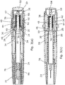
- the autoinjector comprises an outer housing 10 of cylindrical form in the bore of which is disposed a syringe 12 of known form with a barrel 14, a needle 16 extending from the forward end, and a flange 18 at its rear end.
- a medicament is contained within the syringe and can be expressed through the needle by a piston 20 inside the barrel.
- the syringe is supported and surrounded by moulded plastics shroud/carrier 22 assembly comprising a forward hollow cylindrical portion 24 integrally formed with diametrically opposed springs 26 to either side, and a collar 28 adapted to engage the forward face of the syringe flange.
- a drive mechanism which comprises a first outer spring 36 which acts between the front face of a transverse inner wall 38 at the rear of the housing and a forward flange 40 of a top hat-shaped intermediate member 42.
- An inner, second, spring 44 is received within a cylindrical part of the intermediate member 42 and acts between an inner face of the rear end wall thereof and a circumferential rib 46 on the forward part of a plunger 48.
- the plunger has a resilient hooked arm 50 (see Figures 1 , 3(b) ) which latches around the edge of an aperture in the transverse inner wall 38 of the housing.
- a captive axially slideable trigger button 52 Projecting rearwardly from the rear end of the housing is a captive axially slideable trigger button 52 movable against a rearward bias from the position shown in e.g. Figure 3(b) , where a release finger 54 is spaced rearwardly of the hooked arm 50, to a forward portion where the finger 54 cams the hooked arm to release its retention by the wall 38, thereby allowing the springs 36, 44 to drive the plunger 48 forwardly.
- the plunger is shaped and sized so that it can pass into and down the internal bore of the syringe barrel 14, to urge the piston 20 to express a dose.
- a cylindrical recess In the forward end of the plunger is a cylindrical recess in which is located a small powerful magnet 56.
- the trigger button 52 is biased rearwardly by means of two integral forwardly extending sprung arms 58 with cam surfaces 60 which ride over respective abutments 62 inside the rear of the housing. However, initially, forward movement of the trigger button is prevented by means of two rearwardly extending locking arms 64 which extend back from the rear end of a cap 66.
- the cap covers the whole of the forward end of the housing and has a re-entrant cylindrical portion 68 with claw features 70.
- the claw features 70 slip over the rear end of a needle shield 72 which is secured to the front end of the needle during manufacture.
- the cap 66 fulfils the functions of acting as a safety catch for the trigger button 52, serving as a shield remover.
- a latch 74 formed of pressed steel or other ferro-magnetic material to provide two latch arms 76 which extend forwardly from an anchorage normally to sit in an annular space between the shroud 24 and an inner part of the housing wall.
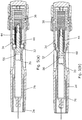
- the user pulls the cap 66 off forwardly which removes the needle shield 22 from the syringe and arms the device by rendering the trigger button 52 operational.
- the user then offers the injection device up to the injection site and presses the trigger button 52.
- the first spring 36 expands to extend the syringe 20 so that the needle penetrates the flesh.
- the second spring 44 remains substantially fully compressed, with the plunger 48 bearing against the piston 20 within the syringe but not moving it relative to the syringe.
- the clearance fingers 32 on the syringe supporting collar 28 are constrained against outward splaying movement by the grooves 34 and so a gap is preserved between the syringe flange 18 and the flange 40 of the intermediate member 42, as long as the fingers are still in engagement with the constraining grooves.
- the fingers 32 exit the constraining grooves 34 at about the same time as forward movement of the syringe is arrested by the compression spring portions 26 bottoming out, the shroud 24 being held against movement by contact with the skin surface.
- the first spring 36 continues to expand to drive the flange 40 of the intermediate member into engagement with the syringe flange 18 thereby contributing to the force required to initiate movement of the piston down the syringe ( Figure 5(b) ). From this position the second spring 44 expands to drive the piston down the barrel of the syringe to express a dose.
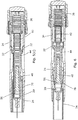
- one or more further magnets or ferro-magnet material may be disposed in the front end of the housing around or in front of the syringe in order to provide a magnetic boost effect as the plunger nears the end of its stroke. It will also be appreciated that the exact position of the magnet(s) and interacting components can be varied.
- This second embodiment incorporates a magnetic coupling embodiment between the plunger 48 and the syringe designed so that during an initial penetration phase of movement the plunger is coupled magnetically to a thrust collar 80 of ferro-magnetic material that is positioned in contact with the rear face of the syringe flange 18.
- a magnetic coupling embodiment between the plunger 48 and the syringe designed so that during an initial penetration phase of movement the plunger is coupled magnetically to a thrust collar 80 of ferro-magnetic material that is positioned in contact with the rear face of the syringe flange 18.
- the spring force acting on the plunger overcomes the magnetic coupling force and the coupling yields so that the plunger is released to move forward relative to the syringe to move the plunger into contact with and to urge the piston forwardly to expel a dose.
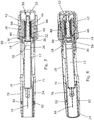
- the plunger moves alongside the ferro-magnetic latching arms 76 and they are attracted inwardly. This is enhanced in the embodiment by provision of two magnets 82 on the forward ends of the latching arms. These magnets are aligned so as to be attached towards and to exert a pull on the magnet 56 in the plunger to provide a magnetically influenced forward boost to the plunger toward the forwardmost end of its stroke.
- the shroud 24 Upon completion of the injection and removal of the device from the site, the shroud 24 extends forwardly as the spring portions 26 reexpand, and as a rearward lip on the shroud passes the magnets, the latching arms move inwards to block retraction movement of the shroud and thereby lock it out.
- the magnets 82 may be housed slideably in through-holes in the housing wall, allowing them also to move inwards with the latching arms as the rearward lip on the shroud passes the magnets, and so provide a visual and tactile confirmation of locking out of the shroud 24.
Landscapes
- Health & Medical Sciences (AREA)
- Engineering & Computer Science (AREA)
- Hematology (AREA)
- Anesthesiology (AREA)
- Biomedical Technology (AREA)
- Heart & Thoracic Surgery (AREA)
- Vascular Medicine (AREA)
- Life Sciences & Earth Sciences (AREA)
- Animal Behavior & Ethology (AREA)
- General Health & Medical Sciences (AREA)
- Public Health (AREA)
- Veterinary Medicine (AREA)
- Environmental & Geological Engineering (AREA)
- Infusion, Injection, And Reservoir Apparatuses (AREA)
Claims (8)
- Dispositif d'injection comprenant :un boîtier allongé (10) ;une seringue (12) disposée dans ledit boîtier et ayant un piston interne (20) pour expulser une dose à partir d'une aiguille (16) à son extrémité avant ;un élément chemise (24) mobile vers l'avant par rapport à la seringue pour protéger l'aiguille après utilisation ;un loquet (74) mobile entre un état verrouillé dans lequel il limite un mouvement vers l'arrière de l'élément d'enveloppe, et un état de libération ;caractérisé par le fait que ledit loquet (74) est déplacé à son état verrouillé par une force magnétique (56).
- Dispositif d'injection selon la revendication 1, comprenant en outre un piston plongeur mobile longitudinalement (48) pour entraîner ledit piston, ledit loquet (76) étant déplacé par une force magnétique (56) agissant entre ledit loquet (ou une partie associée à celui-ci) et ledit piston plongeur.
- Dispositif d'injection selon la revendication 2, dans lequel l'un du piston plongeur (48) et du loquet (74) comporte un aimant ou est magnétisé et l'autre de ceux-ci a une partie ferromagnétique pour être entraînés magnétiquement l'un par rapport à l'autre.
- Dispositif d'injection selon la revendication 3, dans lequel ledit piston plongeur (42) incorpore un aimant (56) ou est magnétisé et ledit loquet (74) comprend une partie (76) de matériau ferromagnétique.
- Dispositif d'injection selon l'une quelconque des revendications précédentes, dans lequel ledit loquet (74) est ancré à l'intérieur du boîtier (10) à une partie d'extrémité arrière et s'étend vers l'avant pour définir une surface de loquet à une région vers l'avant.
- Dispositif d'injection selon l'une quelconque des revendications précédentes, dans lequel ledit élément chemise (24) comprend une partie cylindrique montée pour un mouvement télescopique avec le boîtier.
- Dispositif d'injection selon l'une quelconque des revendications précédentes, dans lequel l'élément chemise (24) comprend une partie vers l'avant d'un composant formé d'un seul tenant comprenant une partie ressort (26) s'étendant vers l'arrière à partir de l'élément chemise et comportant une partie support (28) dans laquelle ladite seringue est reçue.
- Dispositif d'injection selon la revendication 2 ou n'importe quelle revendication dépendante de celle-ci, dans lequel au moins une composante de ladite force magnétique agissant entre le loquet (74) et ledit piston plongeur (48) est dans une direction pour aider la poussée vers l'avant du piston (20) en direction de la fin de la course du piston plongeur.
Priority Applications (1)
| Application Number | Priority Date | Filing Date | Title |
|---|---|---|---|
| EP17162134.5A EP3219348A1 (fr) | 2010-10-14 | 2011-09-19 | Dispositifs d'injection |
Applications Claiming Priority (3)
| Application Number | Priority Date | Filing Date | Title |
|---|---|---|---|
| GBGB1017363.1A GB201017363D0 (en) | 2010-10-14 | 2010-10-14 | Injection devices |
| US39489610P | 2010-10-20 | 2010-10-20 | |
| PCT/GB2011/051754 WO2012049468A2 (fr) | 2010-10-14 | 2011-09-19 | Dispositifs d'injection |
Related Child Applications (2)
| Application Number | Title | Priority Date | Filing Date |
|---|---|---|---|
| EP17162134.5A Division EP3219348A1 (fr) | 2010-10-14 | 2011-09-19 | Dispositifs d'injection |
| EP17162134.5A Division-Into EP3219348A1 (fr) | 2010-10-14 | 2011-09-19 | Dispositifs d'injection |
Publications (2)
| Publication Number | Publication Date |
|---|---|
| EP2632517A2 EP2632517A2 (fr) | 2013-09-04 |
| EP2632517B1 true EP2632517B1 (fr) | 2017-05-03 |
Family
ID=43304569
Family Applications (3)
| Application Number | Title | Priority Date | Filing Date |
|---|---|---|---|
| EP11764253.8A Not-in-force EP2632517B1 (fr) | 2010-10-14 | 2011-09-19 | Dispositif d'injection |
| EP17162134.5A Withdrawn EP3219348A1 (fr) | 2010-10-14 | 2011-09-19 | Dispositifs d'injection |
| EP11776826.7A Revoked EP2632518B1 (fr) | 2010-10-14 | 2011-10-11 | Dispositifs d'injection |
Family Applications After (2)
| Application Number | Title | Priority Date | Filing Date |
|---|---|---|---|
| EP17162134.5A Withdrawn EP3219348A1 (fr) | 2010-10-14 | 2011-09-19 | Dispositifs d'injection |
| EP11776826.7A Revoked EP2632518B1 (fr) | 2010-10-14 | 2011-10-11 | Dispositifs d'injection |
Country Status (5)
| Country | Link |
|---|---|
| US (2) | US9814840B2 (fr) |
| EP (3) | EP2632517B1 (fr) |
| JP (2) | JP6092779B2 (fr) |
| GB (1) | GB201017363D0 (fr) |
| WO (2) | WO2012049468A2 (fr) |
Families Citing this family (35)
| Publication number | Priority date | Publication date | Assignee | Title |
|---|---|---|---|---|
| GB201017363D0 (en) | 2010-10-14 | 2010-11-24 | Owen Mumford Ltd | Injection devices |
| WO2013070789A2 (fr) | 2011-11-07 | 2013-05-16 | Safety Syringes, Inc. | Protection d'aiguille libérable par déclencheur à contact |
| PL2908887T3 (pl) * | 2012-10-19 | 2018-12-31 | Eli Lilly And Company | Automatyczne urządzenie do wstrzykiwania z mechanizmem spustowym |
| PL2968767T3 (pl) | 2013-03-14 | 2017-10-31 | Lilly Co Eli | Zespół wyzwalający do automatycznego urządzenia wstrzykującego |
| AT514484B1 (de) * | 2013-06-24 | 2015-05-15 | Pharma Consult Gmbh | Aktivator für einen Autoinjektor |
| GB2516624B (en) * | 2013-07-25 | 2018-09-19 | Owen Mumford Ltd | Injection devices |
| TWI569832B (zh) | 2013-10-23 | 2017-02-11 | 卡貝歐洲有限公司 | 藥物輸送裝置 |
| GB2530714A (en) | 2014-08-20 | 2016-04-06 | Owen Mumford Ltd | Injection devices |
| DK3223884T3 (da) * | 2014-11-24 | 2023-07-31 | Sanofi Sa | Lægemiddeladministrationsanordning med variabel stempelkraft |
| GB2541445B (en) | 2015-08-20 | 2018-04-18 | Owen Mumford Ltd | Injection device |
| GB2543274A (en) | 2015-10-12 | 2017-04-19 | Owen Mumford Ltd | Injection device |
| CN105498043A (zh) * | 2016-01-15 | 2016-04-20 | 山东威高集团医用高分子制品股份有限公司 | 避光注射器 |
| USD819198S1 (en) | 2016-04-28 | 2018-05-29 | Amgen Inc. | Autoinjector with removable cap |
| US20180015224A1 (en) | 2016-07-13 | 2018-01-18 | California Institute Of Technology | Dampers and Methods for Performing Measurements in an Autoinjector |
| GB2560557A (en) | 2017-03-15 | 2018-09-19 | Owen Mumford Ltd | Injection Device |
| TW201838671A (zh) | 2017-03-15 | 2018-11-01 | 英商歐文蒙福德有限公司 | 注入裝置 |
| GB2560555A (en) | 2017-03-15 | 2018-09-19 | Owen Mumford Ltd | Injection device with deliver phase velocity regulator |
| GB2560554A (en) | 2017-03-15 | 2018-09-19 | Owen Mumford Ltd | Injection device with gap reduction mechanism |
| WO2019175615A1 (fr) * | 2018-03-14 | 2019-09-19 | Biocorp Production S.A. | Dispositif de régulation de la dose pour dispositifs d'administration de médicament injectable |
| EP3626288A1 (fr) * | 2018-09-19 | 2020-03-25 | Tecpharma Licensing AG | Module supplémentaire électronique pour appareils d'injection |
| GB2577549B (en) * | 2018-09-28 | 2021-08-04 | Owen Mumford Ltd | Injection device with commit feature |
| MA54048A (fr) | 2018-11-01 | 2022-02-09 | Amgen Inc | Dispositifs d'administration de médicament avec rétraction partielle de l'organe d'administration de médicament |
| EP3930799A1 (fr) * | 2019-02-26 | 2022-01-05 | Becton Dickinson France | Auto-injecteur avec couvre-aiguille |
| CN110215570A (zh) * | 2019-04-19 | 2019-09-10 | 吴银洪 | 具有互斥张力稳定的全自动固体传感器体内注射器 |
| USD1010811S1 (en) | 2019-09-30 | 2024-01-09 | Amgen Inc. | Handheld drug delivery device |
| USD1030041S1 (en) | 2020-01-14 | 2024-06-04 | Amgen Inc. | Handheld drug delivery device |
| USD1030040S1 (en) | 2020-01-14 | 2024-06-04 | Amgen Inc. | Handheld drug delivery device |
| US11235105B2 (en) | 2020-03-20 | 2022-02-01 | Alexander Nikon | Auto-injector |
| USD973866S1 (en) | 2020-11-05 | 2022-12-27 | Amgen Inc. | Handheld drug delivery device |
| USD974547S1 (en) | 2020-11-05 | 2023-01-03 | Amgen Inc. | Handheld drug delivery device |
| USD962423S1 (en) | 2020-11-05 | 2022-08-30 | Amgen Inc. | Handheld drug delivery device |
| USD985116S1 (en) | 2021-03-10 | 2023-05-02 | Amgen Inc. | Handheld drug delivery device |
| USD985118S1 (en) | 2021-03-10 | 2023-05-02 | Amgen Inc. | Handheld drug delivery device |
| USD985117S1 (en) | 2021-03-10 | 2023-05-02 | Amgen Inc. | Handheld drug delivery device |
| USD985119S1 (en) | 2021-03-30 | 2023-05-02 | Amgen Inc. | Handheld drug delivery device |
Family Cites Families (52)
| Publication number | Priority date | Publication date | Assignee | Title |
|---|---|---|---|---|
| GB686343A (en) | 1950-09-26 | 1953-01-21 | Becton Dickinson Co | Improvements relating to hypodermic injection devices |
| BE755224A (fr) | 1969-08-25 | 1971-02-24 | Philips Nv | Seringue d'injection |
| US3712301A (en) * | 1971-01-11 | 1973-01-23 | Survival Technology | Gun type hypodermic injector with rapid cartridge displacement within holder |
| FR2348709A1 (fr) * | 1976-04-23 | 1977-11-18 | Pistor Michel | Procede de traitement mesotherapique et dispositif d'injection,formant micro-injecteur automatique,en comportant application |
| US5360410A (en) * | 1991-01-16 | 1994-11-01 | Senetek Plc | Safety syringe for mixing two-component medicaments |
| EP0518416A1 (fr) | 1991-06-13 | 1992-12-16 | Duphar International Research B.V | Dispositif d'injection |
| GB9200219D0 (en) | 1992-01-07 | 1992-02-26 | Medimech Int Ltd | Automatic injectors |
| US5599309A (en) | 1993-03-24 | 1997-02-04 | Owen Mumford Limited | Injection devices |
| US5709662A (en) | 1996-08-23 | 1998-01-20 | Becton Dickinson France, S.A. | Cartridge for an injection device |
| GB9714948D0 (en) | 1997-07-16 | 1997-09-17 | Owen Mumford Ltd | Improvements relating to injection devices |
| DE19731778A1 (de) | 1997-07-24 | 1999-02-11 | Leon Helma Christina | Spritzvorrichtung für medizinische Anwendungen |
| US6616639B2 (en) * | 1998-04-17 | 2003-09-09 | Becton, Dickinson And Company | Safety shield system for syringes |
| WO2000015280A1 (fr) | 1998-09-15 | 2000-03-23 | Njc Innovations | Dispositifs d'administration de substances therapeutiques a seringue motorisee |
| GB2342047A (en) | 1998-09-25 | 2000-04-05 | Charles Mcnairn | Single use syringe |
| JP2002119589A (ja) * | 2000-10-18 | 2002-04-23 | Nipro Corp | 留置針組立体 |
| GB0119520D0 (en) | 2001-08-10 | 2001-10-03 | Owen Mumford Ltd | Improvements relating to injection devices |
| US6939323B2 (en) | 2001-10-26 | 2005-09-06 | Massachusetts Institute Of Technology | Needleless injector |
| US7517440B2 (en) * | 2002-07-17 | 2009-04-14 | Eksigent Technologies Llc | Electrokinetic delivery systems, devices and methods |
| JP2007518460A (ja) * | 2003-05-09 | 2007-07-12 | イントラヴァック インコーポレーテッド | 皮内、皮下及び筋肉内注射用の無針注射器及びアンプル |
| GB0315600D0 (en) | 2003-07-04 | 2003-08-13 | Owen Mumford Ltd | Improvements relating to automatic injection devices |
| DE10342059B4 (de) | 2003-09-11 | 2007-03-01 | Tecpharma Licensing Ag | Verabreichungsvorrichtung mit Einstech- und Ausschütteinrichtung |
| US20050101919A1 (en) | 2003-11-07 | 2005-05-12 | Lennart Brunnberg | Device for an injector |
| CH696421A5 (de) | 2003-12-18 | 2007-06-15 | Tecpharma Licensing Ag | Autoinjektor mit Arretierung des Wirkstoffbehälters. |
| CN100502962C (zh) | 2004-10-27 | 2009-06-24 | 杨章民 | 安全注射器 |
| BRPI0518833B8 (pt) * | 2004-12-07 | 2021-06-22 | Becton Dickinson Co | disposição e método para tornar uma agulha segura |
| US7833189B2 (en) | 2005-02-11 | 2010-11-16 | Massachusetts Institute Of Technology | Controlled needle-free transport |
| FR2884721A1 (fr) | 2005-04-20 | 2006-10-27 | Becton Dickinson France Soc Pa | Ensemble d'injection et dispositif d'assistance a l'injection |
| DE202005010389U1 (de) | 2005-07-01 | 2005-09-08 | Tecpharma Licensing Ag | Magnetische Kolbenstangenrückführung und Kolbenstangenfixierung |
| JP4983180B2 (ja) * | 2005-09-20 | 2012-07-25 | パナソニック株式会社 | 穿刺機能付注射装置、穿刺機能付注射装置の制御方法、薬液投与装置、および薬液投与装置の制御方法 |
| EP2010249A2 (fr) | 2006-04-04 | 2009-01-07 | Vnus Medical Technologies, Inc. | Procede et appareil pour generer une mousse de traitement vasculaire |
| JP4973025B2 (ja) * | 2006-06-26 | 2012-07-11 | ニプロ株式会社 | 安全針組立体 |
| US20080086089A1 (en) * | 2006-07-10 | 2008-04-10 | Isaacson S Ray | Magnetically induced safety technology |
| FR2905273B1 (fr) | 2006-09-06 | 2009-04-03 | Becton Dickinson France Soc Pa | Dispositif d'injection automatique avec moyen de temporisation. |
| GB2458586B (en) | 2006-11-21 | 2011-10-12 | Intelliject Llc | Injection device for medicament delivery |
| EP2129414A1 (fr) | 2007-03-22 | 2009-12-09 | Tecpharma Licensing AG | Dispositif d'injection à systèmes de sécurité anti-déclenchement |
| DK2162170T3 (da) | 2007-07-06 | 2011-06-14 | Shl Group Ab | Enkeltskudsinjektionssprøjte med dobbeltfjedre |
| US8308695B2 (en) | 2007-11-14 | 2012-11-13 | Shl Group Ab | Automatic injection device with actively triggered syringe withdrawal |
| US8105292B2 (en) * | 2008-02-11 | 2012-01-31 | Safety Syringes, Inc. | Reconstitution means for safety device |
| EP2268342B1 (fr) | 2008-03-10 | 2015-09-16 | Antares Pharma, Inc. | Dispositif de sécurité pour injecteur |
| GB2460398A (en) * | 2008-05-20 | 2009-12-02 | Owen Mumford Ltd | Auto-injector having a magnetic injection indicator and a needle sheath retainer |
| KR20110037979A (ko) * | 2008-05-30 | 2011-04-13 | 알러간, 인코포레이티드 | 액체 상태 또는 젤 상태의 연조직 증대 필러, 생활성 제제 및 기타 생체적합성 물질을 위한 주사 장치 |
| JP2010000300A (ja) * | 2008-06-23 | 2010-01-07 | Nipro Corp | 安全針組立体 |
| US8167844B2 (en) * | 2008-08-14 | 2012-05-01 | Protectus Medical Devices, Inc. | Safety IV needle/cannula introducer |
| GB0821492D0 (en) | 2008-11-25 | 2008-12-31 | Team Holdings Uk Ltd | Integrated auto-injector cartridge system |
| GB0823693D0 (en) * | 2008-12-31 | 2009-02-04 | Owen Mumford Ltd | Autoinjector |
| GB0900930D0 (en) | 2009-01-20 | 2009-03-04 | Future Injection Technologies Ltd | Injection device |
| GB2467904B (en) | 2009-02-17 | 2013-06-12 | Oval Medical Technologies Ltd | Drug container and delivery mechanism |
| FI2255842T4 (fi) | 2009-05-26 | 2023-08-31 | Neulansuojusyksikkö | |
| US20110054411A1 (en) * | 2009-08-19 | 2011-03-03 | Safety Syringes, Inc. | Patient-Contact Activated Needle Stick Safety Device |
| CN107715256B (zh) * | 2009-10-16 | 2020-08-14 | 詹森生物科技公司 | 手掌激活型药物递送装置 |
| GB201017363D0 (en) | 2010-10-14 | 2010-11-24 | Owen Mumford Ltd | Injection devices |
| EP3366337B1 (fr) | 2009-10-21 | 2019-12-04 | Owen Mumford Limited | Auto-injecteur |
-
2010
- 2010-10-14 GB GBGB1017363.1A patent/GB201017363D0/en not_active Ceased
-
2011
- 2011-09-19 EP EP11764253.8A patent/EP2632517B1/fr not_active Not-in-force
- 2011-09-19 EP EP17162134.5A patent/EP3219348A1/fr not_active Withdrawn
- 2011-09-19 US US13/878,479 patent/US9814840B2/en not_active Expired - Fee Related
- 2011-09-19 WO PCT/GB2011/051754 patent/WO2012049468A2/fr active Application Filing
- 2011-09-19 JP JP2013533277A patent/JP6092779B2/ja not_active Expired - Fee Related
- 2011-10-11 EP EP11776826.7A patent/EP2632518B1/fr not_active Revoked
- 2011-10-11 WO PCT/GB2011/051950 patent/WO2012049484A2/fr active Application Filing
- 2011-10-11 US US13/879,448 patent/US9579464B2/en not_active Expired - Fee Related
-
2016
- 2016-10-07 JP JP2016199412A patent/JP2017035517A/ja not_active Ceased
Also Published As
| Publication number | Publication date |
|---|---|
| EP2632517A2 (fr) | 2013-09-04 |
| EP2632518A2 (fr) | 2013-09-04 |
| WO2012049484A2 (fr) | 2012-04-19 |
| JP6092779B2 (ja) | 2017-03-08 |
| US20130197442A1 (en) | 2013-08-01 |
| JP2017035517A (ja) | 2017-02-16 |
| WO2012049468A2 (fr) | 2012-04-19 |
| US9814840B2 (en) | 2017-11-14 |
| US20130281933A1 (en) | 2013-10-24 |
| EP3219348A1 (fr) | 2017-09-20 |
| GB201017363D0 (en) | 2010-11-24 |
| US9579464B2 (en) | 2017-02-28 |
| EP2632518B1 (fr) | 2016-06-22 |
| WO2012049484A3 (fr) | 2012-11-01 |
| WO2012049468A3 (fr) | 2012-07-05 |
| JP2013540016A (ja) | 2013-10-31 |
Similar Documents
| Publication | Publication Date | Title |
|---|---|---|
| EP2632517B1 (fr) | Dispositif d'injection | |
| US9707344B2 (en) | Autoinjector | |
| AU2006310971B2 (en) | Autoinjector activation triggering element | |
| EP2175917B1 (fr) | Dispositif d'injection à mécanisme de verrouillage pour porte-seringue | |
| EP2175915B1 (fr) | Dispositif d'injection à mécanisme de verrouillage pour porte-seringue | |
| CN102089023B (zh) | 具有磁性注射完成指示器和针护套移除装置的注射装置 | |
| GB2553770A (en) | Injection device | |
| EP4173651A1 (fr) | Auto-injecteur | |
| WO2023073049A1 (fr) | Auto-injecteur | |
| EP4387688A1 (fr) | Auto-injecteur | |
| EP4392096A1 (fr) | Mécanisme de libération d'auto-injecteur |
Legal Events
| Date | Code | Title | Description |
|---|---|---|---|
| PUAI | Public reference made under article 153(3) epc to a published international application that has entered the european phase |
Free format text: ORIGINAL CODE: 0009012 |
|
| 17P | Request for examination filed |
Effective date: 20130430 |
|
| AK | Designated contracting states |
Kind code of ref document: A2 Designated state(s): AL AT BE BG CH CY CZ DE DK EE ES FI FR GB GR HR HU IE IS IT LI LT LU LV MC MK MT NL NO PL PT RO RS SE SI SK SM TR |
|
| DAX | Request for extension of the european patent (deleted) | ||
| 17Q | First examination report despatched |
Effective date: 20150710 |
|
| GRAP | Despatch of communication of intention to grant a patent |
Free format text: ORIGINAL CODE: EPIDOSNIGR1 |
|
| STAA | Information on the status of an ep patent application or granted ep patent |
Free format text: STATUS: GRANT OF PATENT IS INTENDED |
|
| INTG | Intention to grant announced |
Effective date: 20161202 |
|
| GRAS | Grant fee paid |
Free format text: ORIGINAL CODE: EPIDOSNIGR3 |
|
| GRAA | (expected) grant |
Free format text: ORIGINAL CODE: 0009210 |
|
| STAA | Information on the status of an ep patent application or granted ep patent |
Free format text: STATUS: THE PATENT HAS BEEN GRANTED |
|
| AK | Designated contracting states |
Kind code of ref document: B1 Designated state(s): AL AT BE BG CH CY CZ DE DK EE ES FI FR GB GR HR HU IE IS IT LI LT LU LV MC MK MT NL NO PL PT RO RS SE SI SK SM TR |
|
| REG | Reference to a national code |
Ref country code: GB Ref legal event code: FG4D |
|
| REG | Reference to a national code |
Ref country code: AT Ref legal event code: REF Ref document number: 889281 Country of ref document: AT Kind code of ref document: T Effective date: 20170515 Ref country code: CH Ref legal event code: EP |
|
| REG | Reference to a national code |
Ref country code: IE Ref legal event code: FG4D |
|
| REG | Reference to a national code |
Ref country code: DE Ref legal event code: R096 Ref document number: 602011037610 Country of ref document: DE |
|
| REG | Reference to a national code |
Ref country code: DE Ref legal event code: R082 Ref document number: 602011037610 Country of ref document: DE Representative=s name: ZEITLER VOLPERT KANDLBINDER PATENT- UND RECHTS, DE |
|
| REG | Reference to a national code |
Ref country code: NL Ref legal event code: MP Effective date: 20170503 |
|
| REG | Reference to a national code |
Ref country code: AT Ref legal event code: MK05 Ref document number: 889281 Country of ref document: AT Kind code of ref document: T Effective date: 20170503 |
|
| REG | Reference to a national code |
Ref country code: LT Ref legal event code: MG4D |
|
| REG | Reference to a national code |
Ref country code: FR Ref legal event code: PLFP Year of fee payment: 7 |
|
| PG25 | Lapsed in a contracting state [announced via postgrant information from national office to epo] |
Ref country code: ES Free format text: LAPSE BECAUSE OF FAILURE TO SUBMIT A TRANSLATION OF THE DESCRIPTION OR TO PAY THE FEE WITHIN THE PRESCRIBED TIME-LIMIT Effective date: 20170503 Ref country code: AT Free format text: LAPSE BECAUSE OF FAILURE TO SUBMIT A TRANSLATION OF THE DESCRIPTION OR TO PAY THE FEE WITHIN THE PRESCRIBED TIME-LIMIT Effective date: 20170503 Ref country code: NO Free format text: LAPSE BECAUSE OF FAILURE TO SUBMIT A TRANSLATION OF THE DESCRIPTION OR TO PAY THE FEE WITHIN THE PRESCRIBED TIME-LIMIT Effective date: 20170803 Ref country code: LT Free format text: LAPSE BECAUSE OF FAILURE TO SUBMIT A TRANSLATION OF THE DESCRIPTION OR TO PAY THE FEE WITHIN THE PRESCRIBED TIME-LIMIT Effective date: 20170503 Ref country code: HR Free format text: LAPSE BECAUSE OF FAILURE TO SUBMIT A TRANSLATION OF THE DESCRIPTION OR TO PAY THE FEE WITHIN THE PRESCRIBED TIME-LIMIT Effective date: 20170503 Ref country code: FI Free format text: LAPSE BECAUSE OF FAILURE TO SUBMIT A TRANSLATION OF THE DESCRIPTION OR TO PAY THE FEE WITHIN THE PRESCRIBED TIME-LIMIT Effective date: 20170503 Ref country code: GR Free format text: LAPSE BECAUSE OF FAILURE TO SUBMIT A TRANSLATION OF THE DESCRIPTION OR TO PAY THE FEE WITHIN THE PRESCRIBED TIME-LIMIT Effective date: 20170804 |
|
| PGFP | Annual fee paid to national office [announced via postgrant information from national office to epo] |
Ref country code: GB Payment date: 20170920 Year of fee payment: 7 Ref country code: DE Payment date: 20170926 Year of fee payment: 7 Ref country code: FR Payment date: 20170926 Year of fee payment: 7 |
|
| PG25 | Lapsed in a contracting state [announced via postgrant information from national office to epo] |
Ref country code: BG Free format text: LAPSE BECAUSE OF FAILURE TO SUBMIT A TRANSLATION OF THE DESCRIPTION OR TO PAY THE FEE WITHIN THE PRESCRIBED TIME-LIMIT Effective date: 20170803 Ref country code: LV Free format text: LAPSE BECAUSE OF FAILURE TO SUBMIT A TRANSLATION OF THE DESCRIPTION OR TO PAY THE FEE WITHIN THE PRESCRIBED TIME-LIMIT Effective date: 20170503 Ref country code: RS Free format text: LAPSE BECAUSE OF FAILURE TO SUBMIT A TRANSLATION OF THE DESCRIPTION OR TO PAY THE FEE WITHIN THE PRESCRIBED TIME-LIMIT Effective date: 20170503 Ref country code: SE Free format text: LAPSE BECAUSE OF FAILURE TO SUBMIT A TRANSLATION OF THE DESCRIPTION OR TO PAY THE FEE WITHIN THE PRESCRIBED TIME-LIMIT Effective date: 20170503 Ref country code: PL Free format text: LAPSE BECAUSE OF FAILURE TO SUBMIT A TRANSLATION OF THE DESCRIPTION OR TO PAY THE FEE WITHIN THE PRESCRIBED TIME-LIMIT Effective date: 20170503 Ref country code: IS Free format text: LAPSE BECAUSE OF FAILURE TO SUBMIT A TRANSLATION OF THE DESCRIPTION OR TO PAY THE FEE WITHIN THE PRESCRIBED TIME-LIMIT Effective date: 20170903 Ref country code: NL Free format text: LAPSE BECAUSE OF FAILURE TO SUBMIT A TRANSLATION OF THE DESCRIPTION OR TO PAY THE FEE WITHIN THE PRESCRIBED TIME-LIMIT Effective date: 20170503 |
|
| PG25 | Lapsed in a contracting state [announced via postgrant information from national office to epo] |
Ref country code: DK Free format text: LAPSE BECAUSE OF FAILURE TO SUBMIT A TRANSLATION OF THE DESCRIPTION OR TO PAY THE FEE WITHIN THE PRESCRIBED TIME-LIMIT Effective date: 20170503 Ref country code: EE Free format text: LAPSE BECAUSE OF FAILURE TO SUBMIT A TRANSLATION OF THE DESCRIPTION OR TO PAY THE FEE WITHIN THE PRESCRIBED TIME-LIMIT Effective date: 20170503 Ref country code: SK Free format text: LAPSE BECAUSE OF FAILURE TO SUBMIT A TRANSLATION OF THE DESCRIPTION OR TO PAY THE FEE WITHIN THE PRESCRIBED TIME-LIMIT Effective date: 20170503 Ref country code: RO Free format text: LAPSE BECAUSE OF FAILURE TO SUBMIT A TRANSLATION OF THE DESCRIPTION OR TO PAY THE FEE WITHIN THE PRESCRIBED TIME-LIMIT Effective date: 20170503 Ref country code: CZ Free format text: LAPSE BECAUSE OF FAILURE TO SUBMIT A TRANSLATION OF THE DESCRIPTION OR TO PAY THE FEE WITHIN THE PRESCRIBED TIME-LIMIT Effective date: 20170503 |
|
| REG | Reference to a national code |
Ref country code: DE Ref legal event code: R097 Ref document number: 602011037610 Country of ref document: DE |
|
| PG25 | Lapsed in a contracting state [announced via postgrant information from national office to epo] |
Ref country code: SM Free format text: LAPSE BECAUSE OF FAILURE TO SUBMIT A TRANSLATION OF THE DESCRIPTION OR TO PAY THE FEE WITHIN THE PRESCRIBED TIME-LIMIT Effective date: 20170503 Ref country code: IT Free format text: LAPSE BECAUSE OF FAILURE TO SUBMIT A TRANSLATION OF THE DESCRIPTION OR TO PAY THE FEE WITHIN THE PRESCRIBED TIME-LIMIT Effective date: 20170503 |
|
| PLBE | No opposition filed within time limit |
Free format text: ORIGINAL CODE: 0009261 |
|
| STAA | Information on the status of an ep patent application or granted ep patent |
Free format text: STATUS: NO OPPOSITION FILED WITHIN TIME LIMIT |
|
| 26N | No opposition filed |
Effective date: 20180206 |
|
| REG | Reference to a national code |
Ref country code: CH Ref legal event code: PL |
|
| PG25 | Lapsed in a contracting state [announced via postgrant information from national office to epo] |
Ref country code: SI Free format text: LAPSE BECAUSE OF FAILURE TO SUBMIT A TRANSLATION OF THE DESCRIPTION OR TO PAY THE FEE WITHIN THE PRESCRIBED TIME-LIMIT Effective date: 20170503 Ref country code: MC Free format text: LAPSE BECAUSE OF FAILURE TO SUBMIT A TRANSLATION OF THE DESCRIPTION OR TO PAY THE FEE WITHIN THE PRESCRIBED TIME-LIMIT Effective date: 20170503 |
|
| REG | Reference to a national code |
Ref country code: IE Ref legal event code: MM4A |
|
| REG | Reference to a national code |
Ref country code: BE Ref legal event code: MM Effective date: 20170930 |
|
| PG25 | Lapsed in a contracting state [announced via postgrant information from national office to epo] |
Ref country code: LU Free format text: LAPSE BECAUSE OF NON-PAYMENT OF DUE FEES Effective date: 20170919 |
|
| PG25 | Lapsed in a contracting state [announced via postgrant information from national office to epo] |
Ref country code: IE Free format text: LAPSE BECAUSE OF NON-PAYMENT OF DUE FEES Effective date: 20170919 Ref country code: LI Free format text: LAPSE BECAUSE OF NON-PAYMENT OF DUE FEES Effective date: 20170930 Ref country code: CH Free format text: LAPSE BECAUSE OF NON-PAYMENT OF DUE FEES Effective date: 20170930 |
|
| PG25 | Lapsed in a contracting state [announced via postgrant information from national office to epo] |
Ref country code: BE Free format text: LAPSE BECAUSE OF NON-PAYMENT OF DUE FEES Effective date: 20170930 |
|
| PG25 | Lapsed in a contracting state [announced via postgrant information from national office to epo] |
Ref country code: MT Free format text: LAPSE BECAUSE OF NON-PAYMENT OF DUE FEES Effective date: 20170919 |
|
| REG | Reference to a national code |
Ref country code: DE Ref legal event code: R119 Ref document number: 602011037610 Country of ref document: DE |
|
| GBPC | Gb: european patent ceased through non-payment of renewal fee |
Effective date: 20180919 |
|
| PG25 | Lapsed in a contracting state [announced via postgrant information from national office to epo] |
Ref country code: HU Free format text: LAPSE BECAUSE OF FAILURE TO SUBMIT A TRANSLATION OF THE DESCRIPTION OR TO PAY THE FEE WITHIN THE PRESCRIBED TIME-LIMIT; INVALID AB INITIO Effective date: 20110919 |
|
| PG25 | Lapsed in a contracting state [announced via postgrant information from national office to epo] |
Ref country code: DE Free format text: LAPSE BECAUSE OF NON-PAYMENT OF DUE FEES Effective date: 20190402 |
|
| PG25 | Lapsed in a contracting state [announced via postgrant information from national office to epo] |
Ref country code: FR Free format text: LAPSE BECAUSE OF NON-PAYMENT OF DUE FEES Effective date: 20180930 |
|
| PG25 | Lapsed in a contracting state [announced via postgrant information from national office to epo] |
Ref country code: GB Free format text: LAPSE BECAUSE OF NON-PAYMENT OF DUE FEES Effective date: 20180919 Ref country code: CY Free format text: LAPSE BECAUSE OF NON-PAYMENT OF DUE FEES Effective date: 20170503 |
|
| PG25 | Lapsed in a contracting state [announced via postgrant information from national office to epo] |
Ref country code: MK Free format text: LAPSE BECAUSE OF FAILURE TO SUBMIT A TRANSLATION OF THE DESCRIPTION OR TO PAY THE FEE WITHIN THE PRESCRIBED TIME-LIMIT Effective date: 20170503 |
|
| PG25 | Lapsed in a contracting state [announced via postgrant information from national office to epo] |
Ref country code: TR Free format text: LAPSE BECAUSE OF FAILURE TO SUBMIT A TRANSLATION OF THE DESCRIPTION OR TO PAY THE FEE WITHIN THE PRESCRIBED TIME-LIMIT Effective date: 20170503 |
|
| PG25 | Lapsed in a contracting state [announced via postgrant information from national office to epo] |
Ref country code: PT Free format text: LAPSE BECAUSE OF FAILURE TO SUBMIT A TRANSLATION OF THE DESCRIPTION OR TO PAY THE FEE WITHIN THE PRESCRIBED TIME-LIMIT Effective date: 20170503 |
|
| PG25 | Lapsed in a contracting state [announced via postgrant information from national office to epo] |
Ref country code: AL Free format text: LAPSE BECAUSE OF FAILURE TO SUBMIT A TRANSLATION OF THE DESCRIPTION OR TO PAY THE FEE WITHIN THE PRESCRIBED TIME-LIMIT Effective date: 20170503 |