EP2632230B1 - Dispositif de chauffage par induction, appareil de cuisson utilisant un tel dispositif et procédé d'assemblage correspondant - Google Patents
Dispositif de chauffage par induction, appareil de cuisson utilisant un tel dispositif et procédé d'assemblage correspondant Download PDFInfo
- Publication number
- EP2632230B1 EP2632230B1 EP12156872.9A EP12156872A EP2632230B1 EP 2632230 B1 EP2632230 B1 EP 2632230B1 EP 12156872 A EP12156872 A EP 12156872A EP 2632230 B1 EP2632230 B1 EP 2632230B1
- Authority
- EP
- European Patent Office
- Prior art keywords
- central
- induction heating
- heating device
- coil assembly
- support plate
- Prior art date
- Legal status (The legal status is an assumption and is not a legal conclusion. Google has not performed a legal analysis and makes no representation as to the accuracy of the status listed.)
- Active
Links
- 230000006698 induction Effects 0.000 title claims description 27
- 238000010438 heat treatment Methods 0.000 title claims description 24
- 238000000034 method Methods 0.000 title claims description 8
- 238000010411 cooking Methods 0.000 title claims 2
- 229910000859 α-Fe Inorganic materials 0.000 claims description 30
- 239000011521 glass Substances 0.000 claims description 9
- 239000010445 mica Substances 0.000 claims description 8
- 229910052618 mica group Inorganic materials 0.000 claims description 8
- 239000000463 material Substances 0.000 claims description 4
- 239000013536 elastomeric material Substances 0.000 claims description 2
- 238000009413 insulation Methods 0.000 claims description 2
- 239000003292 glue Substances 0.000 description 15
- 239000000243 solution Substances 0.000 description 7
- XAGFODPZIPBFFR-UHFFFAOYSA-N aluminium Chemical compound [Al] XAGFODPZIPBFFR-UHFFFAOYSA-N 0.000 description 6
- 229910052782 aluminium Inorganic materials 0.000 description 6
- RYGMFSIKBFXOCR-UHFFFAOYSA-N Copper Chemical compound [Cu] RYGMFSIKBFXOCR-UHFFFAOYSA-N 0.000 description 5
- 229910052802 copper Inorganic materials 0.000 description 5
- 239000010949 copper Substances 0.000 description 5
- 239000011490 mineral wool Substances 0.000 description 5
- 239000004033 plastic Substances 0.000 description 5
- 239000000919 ceramic Substances 0.000 description 3
- 230000008569 process Effects 0.000 description 3
- 239000005060 rubber Substances 0.000 description 3
- 230000008901 benefit Effects 0.000 description 2
- 230000005672 electromagnetic field Effects 0.000 description 2
- 238000002347 injection Methods 0.000 description 2
- 239000007924 injection Substances 0.000 description 2
- 238000003780 insertion Methods 0.000 description 2
- 230000037431 insertion Effects 0.000 description 2
- 230000009467 reduction Effects 0.000 description 2
- 229920001169 thermoplastic Polymers 0.000 description 2
- 229920001187 thermosetting polymer Polymers 0.000 description 2
- 239000004416 thermosoftening plastic Substances 0.000 description 2
- 241000533950 Leucojum Species 0.000 description 1
- 230000009471 action Effects 0.000 description 1
- 239000012141 concentrate Substances 0.000 description 1
- 230000000694 effects Effects 0.000 description 1
- 230000005294 ferromagnetic effect Effects 0.000 description 1
- 230000005291 magnetic effect Effects 0.000 description 1
- 239000012815 thermoplastic material Substances 0.000 description 1
- 239000004634 thermosetting polymer Substances 0.000 description 1
Images
Classifications
-
- H—ELECTRICITY
- H05—ELECTRIC TECHNIQUES NOT OTHERWISE PROVIDED FOR
- H05B—ELECTRIC HEATING; ELECTRIC LIGHT SOURCES NOT OTHERWISE PROVIDED FOR; CIRCUIT ARRANGEMENTS FOR ELECTRIC LIGHT SOURCES, IN GENERAL
- H05B6/00—Heating by electric, magnetic or electromagnetic fields
- H05B6/02—Induction heating
- H05B6/10—Induction heating apparatus, other than furnaces, for specific applications
- H05B6/12—Cooking devices
- H05B6/1209—Cooking devices induction cooking plates or the like and devices to be used in combination with them
-
- B—PERFORMING OPERATIONS; TRANSPORTING
- B29—WORKING OF PLASTICS; WORKING OF SUBSTANCES IN A PLASTIC STATE IN GENERAL
- B29C—SHAPING OR JOINING OF PLASTICS; SHAPING OF MATERIAL IN A PLASTIC STATE, NOT OTHERWISE PROVIDED FOR; AFTER-TREATMENT OF THE SHAPED PRODUCTS, e.g. REPAIRING
- B29C45/00—Injection moulding, i.e. forcing the required volume of moulding material through a nozzle into a closed mould; Apparatus therefor
- B29C45/16—Making multilayered or multicoloured articles
-
- H—ELECTRICITY
- H01—ELECTRIC ELEMENTS
- H01F—MAGNETS; INDUCTANCES; TRANSFORMERS; SELECTION OF MATERIALS FOR THEIR MAGNETIC PROPERTIES
- H01F41/00—Apparatus or processes specially adapted for manufacturing or assembling magnets, inductances or transformers; Apparatus or processes specially adapted for manufacturing materials characterised by their magnetic properties
-
- H—ELECTRICITY
- H05—ELECTRIC TECHNIQUES NOT OTHERWISE PROVIDED FOR
- H05B—ELECTRIC HEATING; ELECTRIC LIGHT SOURCES NOT OTHERWISE PROVIDED FOR; CIRCUIT ARRANGEMENTS FOR ELECTRIC LIGHT SOURCES, IN GENERAL
- H05B1/00—Details of electric heating devices
- H05B1/02—Automatic switching arrangements specially adapted to apparatus ; Control of heating devices
- H05B1/0227—Applications
- H05B1/0252—Domestic applications
- H05B1/0258—For cooking
- H05B1/0261—For cooking of food
- H05B1/0266—Cooktops
-
- H—ELECTRICITY
- H05—ELECTRIC TECHNIQUES NOT OTHERWISE PROVIDED FOR
- H05B—ELECTRIC HEATING; ELECTRIC LIGHT SOURCES NOT OTHERWISE PROVIDED FOR; CIRCUIT ARRANGEMENTS FOR ELECTRIC LIGHT SOURCES, IN GENERAL
- H05B6/00—Heating by electric, magnetic or electromagnetic fields
- H05B6/02—Induction heating
- H05B6/10—Induction heating apparatus, other than furnaces, for specific applications
- H05B6/12—Cooking devices
- H05B6/1209—Cooking devices induction cooking plates or the like and devices to be used in combination with them
- H05B6/1245—Cooking devices induction cooking plates or the like and devices to be used in combination with them with special coil arrangements
- H05B6/1254—Cooking devices induction cooking plates or the like and devices to be used in combination with them with special coil arrangements using conductive pieces to direct the induced magnetic field
-
- H—ELECTRICITY
- H05—ELECTRIC TECHNIQUES NOT OTHERWISE PROVIDED FOR
- H05B—ELECTRIC HEATING; ELECTRIC LIGHT SOURCES NOT OTHERWISE PROVIDED FOR; CIRCUIT ARRANGEMENTS FOR ELECTRIC LIGHT SOURCES, IN GENERAL
- H05B6/00—Heating by electric, magnetic or electromagnetic fields
- H05B6/02—Induction heating
- H05B6/36—Coil arrangements
-
- B—PERFORMING OPERATIONS; TRANSPORTING
- B29—WORKING OF PLASTICS; WORKING OF SUBSTANCES IN A PLASTIC STATE IN GENERAL
- B29K—INDEXING SCHEME ASSOCIATED WITH SUBCLASSES B29B, B29C OR B29D, RELATING TO MOULDING MATERIALS OR TO MATERIALS FOR MOULDS, REINFORCEMENTS, FILLERS OR PREFORMED PARTS, e.g. INSERTS
- B29K2021/00—Use of unspecified rubbers as moulding material
-
- B—PERFORMING OPERATIONS; TRANSPORTING
- B29—WORKING OF PLASTICS; WORKING OF SUBSTANCES IN A PLASTIC STATE IN GENERAL
- B29L—INDEXING SCHEME ASSOCIATED WITH SUBCLASS B29C, RELATING TO PARTICULAR ARTICLES
- B29L2031/00—Other particular articles
- B29L2031/779—Heating equipment
-
- H—ELECTRICITY
- H05—ELECTRIC TECHNIQUES NOT OTHERWISE PROVIDED FOR
- H05B—ELECTRIC HEATING; ELECTRIC LIGHT SOURCES NOT OTHERWISE PROVIDED FOR; CIRCUIT ARRANGEMENTS FOR ELECTRIC LIGHT SOURCES, IN GENERAL
- H05B2206/00—Aspects relating to heating by electric, magnetic, or electromagnetic fields covered by group H05B6/00
- H05B2206/02—Induction heating
- H05B2206/022—Special supports for the induction coils
-
- Y—GENERAL TAGGING OF NEW TECHNOLOGICAL DEVELOPMENTS; GENERAL TAGGING OF CROSS-SECTIONAL TECHNOLOGIES SPANNING OVER SEVERAL SECTIONS OF THE IPC; TECHNICAL SUBJECTS COVERED BY FORMER USPC CROSS-REFERENCE ART COLLECTIONS [XRACs] AND DIGESTS
- Y02—TECHNOLOGIES OR APPLICATIONS FOR MITIGATION OR ADAPTATION AGAINST CLIMATE CHANGE
- Y02B—CLIMATE CHANGE MITIGATION TECHNOLOGIES RELATED TO BUILDINGS, e.g. HOUSING, HOUSE APPLIANCES OR RELATED END-USER APPLICATIONS
- Y02B40/00—Technologies aiming at improving the efficiency of home appliances, e.g. induction cooking or efficient technologies for refrigerators, freezers or dish washers
-
- Y—GENERAL TAGGING OF NEW TECHNOLOGICAL DEVELOPMENTS; GENERAL TAGGING OF CROSS-SECTIONAL TECHNOLOGIES SPANNING OVER SEVERAL SECTIONS OF THE IPC; TECHNICAL SUBJECTS COVERED BY FORMER USPC CROSS-REFERENCE ART COLLECTIONS [XRACs] AND DIGESTS
- Y10—TECHNICAL SUBJECTS COVERED BY FORMER USPC
- Y10T—TECHNICAL SUBJECTS COVERED BY FORMER US CLASSIFICATION
- Y10T29/00—Metal working
- Y10T29/49—Method of mechanical manufacture
- Y10T29/49002—Electrical device making
- Y10T29/4902—Electromagnet, transformer or inductor
Definitions
- the present invention relates to an induction heating device comprising a support plate and a coil assembly, between the coil assembly and the support plate being interposed a plurality of ferrite bars.
- ferrite bars we mean any kind of elongated magnetic field concentrator located beneath the coil assembly.
- the above heating devices are used to heat and cook food thanks to heat energy generated in a ferromagnetic container placed above the coil assembly and supported on a ceramic glass or the like.
- the known induction heating devices consist of a series of layers dedicated to different functions. All of them are composed of different materials and geometries. In some solutions layers are connected with glue. All the parts (with the exception of the support plate, usually made of aluminum) have a hole in the center which is designed to allow the insertion of a sensor holder for a thermal sensor contacting the ceramic glass. On the top of the last layer, i.e. the coil assembly, there is a thermal insulating layer for instance of rock wool. The sequence of the layers, starting from the top is: rock wool > glue > copper coil > glue > mica > glue > ferrite > glue > aluminum base. Mica and copper coil are usually supplied as a single assembly.
- heating induction devices for instance as described in EP0713350 , EP1560462 and WO 2011/138715 A1 , comprise a disk-shaped plastic support interposed between the support plate and the coil assembly and having a plurality of housings for containing the ferrite bars. Also in these solutions glue is used for holding together the different layers.
- the technical solution according to the present invention comprises a small and simple plastic central component that exploits the symmetric geometry of the coil assembly in order to design a core that can also preferably integrate the sensor holder and preferably connects the different layers with a quick mechanical snap-engagement fastening system.
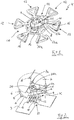
- the induction heating device comprises a central component K composed of a co-injection of two different materials.
- the component K comprises a plastic body 2 of thermoplastic material, on which is co-injected a central part of rubber, the sensor holder 1.
- the plastic body 2 is made of thermoplastic or thermosetting polymer having a high Young's modulus.
- the shape of the component K recalls that of a snowflake, since it comprises a central portion 10 shaped as a regular polygon, for instance an hexagon (where the rubber or similar elastomeric material is centrally co-injected), on whose apexes 10a are integrally formed other regular auxiliary polygons 12, in the shown example triangles.
- Such shape is due to the main technical purpose of the component K, i.e. to constrain the ends of ferrite bars 4 in the position required to channel or concentrate the electromagnetic field.
- a quadrangular seat 14 (open on top and bottom) for an end 4a of a ferrite bar 4.
- the central component K defines six seats 14 for the ferrite bars, but of course it can be formed with a different number of seats (as shown in figures 6 and 7 ).
- the thickness of the portion 10 corresponds to the thickness of the ferrite bars 4, so that all such components can be sandwiched between other components of the induction heater (as it will be clear from the following description) in a very precise way in terms of final thickness.
- the dimension of the seats 14 (which allows the assembly of the ferrite bars 4 with a predetermined degree of interference), together with the stiffness of the thermoplastic or thermosetting material allows a very stable position of the ferrite bars 4, despite the forces acting on them during normal operation.
- the sensor holder 1 is a co-injection of rubber, with a total height slightly higher than the thickness of the central portion 10, because the holder 1 needs to generate a spring effect to keep a sensor 8 ( figures 2 and 4 ) pressed on the bottom face of the glass (not shown) of the induction cooktop.
- the central portion 10 of the component K is also provided with a plurality of elastic hooks 16 and 18 which are oriented parallel to the central symmetry axis of the component K.
- a first crown of upper hooks 16 can be seen in figures 1 and 2
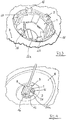
- a second crown of lower hooks 18 can be seen in figure 3 .
- FIG 2 shows the entire induction heater assembly with the central component K.
- a copper coil 6 is stuck on a mica layer 5 with glue and they form a single component.
- the coil is assembled in the following sequence: the central component K is connected to an aluminum base or plate 3 through the lower crown of hooks 18 with a light pressure in order to allow a snap-engaging action of the hooks 18 on a circular edge 22a of a central hole 22 of the base 3 ( figure 3 ).
- the central hole 22 with its edge 22a can be replaced by small slots (not shown) which can be snap-engaged by the lower crowns of hooks 18 for reaching the same techcnial result.
- the dimension of the elastic hooks 18 is selected in order to fix in a stable way the component K on the aluminum base 3 without the use of any glue.
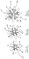
- the ferrite bars 4 are collocated with interference in the defined seats14, obtaining a configuration (shown in figure 5 ) in which the ferrite bars 4 are radially centered on the component K as rays of a star. Then the mica layer 5 and the copper coil 6 assembly is positioned on the central component K and with a little pressure (similarly to what already done for the base 3), connected with the upper hooks 16 so that they snap-engage with a circular edge 24a of a central hole 24 of the coil assembly, visible in Fig. 4 . The component K is interposed and in contact with the aluminum base 3 and with the coil assembly, particularly with the mica layer 5 thereof.
- the rock wool layer 7 is preferably provided with a central hole 7a so that the sensor 8 is interposed between the sensor holder 1 and the ceramic glass of the induction cooktop.
- the embodiment shown in figure 6 differs from the above in the different number of ferrite bars (eight instead of six) in order to match a different size of the coil and in the different shape of the central component K' (octagonal and not hexagonal). Moreover the ferrite bars 4 and 40 have two different dimensions, with the longer bars 4 closer to the sensor holder 1.
- the central component K" has an overall pentagon shape and it is adapted to house ten ferrite bars 4 and 42, also in this case of different length.
Landscapes
- Engineering & Computer Science (AREA)
- Physics & Mathematics (AREA)
- Electromagnetism (AREA)
- Power Engineering (AREA)
- Manufacturing & Machinery (AREA)
- Mechanical Engineering (AREA)
- Food Science & Technology (AREA)
- Induction Heating Cooking Devices (AREA)
- General Induction Heating (AREA)
- Cookers (AREA)
Claims (13)
- Dispositif de chauffage par induction comprenant une plaque de support (3) et un ensemble d'enroulement (5, 6), une pluralité de barres de ferrite (4, 40, 42) étant intercalée entre l'ensemble d'enroulement (5, 6) et la plaque de support (3), un élément central (K, K', K") étant intercalé entre l'ensemble d'enroulement (5, 6) et la plaque de support (3), cet élément (K, K', K", 10) ayant une pluralité de sièges radiaux (14) pour les barres de ferrite (4,40,42) afin de maintenir ces barres dans une position prédéterminée, caractérisé en ce que l'élément central (K. K', K") présente une partie centrale sensiblement plate (10) ayant une forme polygonale et une épaisseur correspondant à l'épaisseur des barres de ferrite (4,40,42), chaque sommet (10a) de la partie centrale polygonale (10) ayant un appendice radial sensiblement plat (12) de forme polygonale de sorte que chaque côté de la partie centrale polygonale (10) et deux côtés en regard de deux appendices adjacents (12) définissent un siège quadrangulaire pour une extrémité (4a) de la barre de ferrite correspondante (4, 40, 42).
- Dispositif de chauffage par induction selon la revendication 1, dans lequel la partie centrale (10) est hexagonale et les appendices (12) sont triangulaires.
- Dispositif de chauffage par induction selon la revendication 1 ou 2, dans lequel l'élément central (K, K', K", 1, 2, 10) est constitué au moins en partie d'un matériau polymère.
- Dispositif de chauffage par induction selon la revendication 3, dans lequel l'élément central (K) comprend une partie centrale (1) constituée d'un matériau élastomère co-injecté avec l'élément (K, K', K", 2, 10) et adaptée pour presser un capteur (8) contre une surface de verre d'une surface de cuisson à l'état de fonctionnement du dispositif de chauffage.
- Dispositif de chauffage par induction selon l'une quelconque des revendications précédentes, dans lequel l'élément central (K, K', K") présente une pluralité de parties de fixation (18) en forme de crochet adaptées pour coopérer avec la plaque de support (3) afin d'engager par encliquetage l'élément central (K, K', K") sur cette plaque.
- Dispositif de chauffage par induction selon l'une quelconque des revendications précédentes, dans lequel l'élément central (K, K', K") présente une pluralité de parties de fixation auxiliaires (16) en forme de crochet adaptées pour coopérer avec un bord (24a) d'un trou central (24) de l'ensemble d'enroulement (5, 6) afin d'engager par encliquetage l'élément central (K, K', K") sur cet ensemble.
- Dispositif de chauffage par induction selon l'une quelconque des revendications précédentes, dans lequel l'ensemble d'enroulement (5 , 6) comprend une couche de mica (5) intercalée entre l'enroulement (6) et les barres de ferrite (4, 40, 42).
- Surface de cuisson ayant au moins un dispositif de chauffage par induction selon l'une quelconque des revendications précédentes, dans laquelle un capteur de température (8) est intercalé entre l'élément central (K) et une plaque de verre de la surface de cuisson.
- Surface de cuisson selon la revendication 8, dans laquelle l'élément central (K) présente un siège (26) pour le capteur de température (8).
- Surface de cuisson selon la revendication 8 ou 9, dans laquelle est intercalée une couche d'isolation thermique (7) entre l'ensemble d'enroulement (5, 6) et la plaque de verre.
- Procédé d'assemblage d'un dispositif de chauffage par induction comprenant une plaque de support (3) et un ensemble d'enroulement (5,6), une pluralité de barres de ferrite (4, 40, 42) étant intercalée entre l'ensemble d'enroulement (5, 6) et la plaque de support (3), caractérisé en ce qu'il comprend les étapes suivantes consistant à :- engager par encliquetage un élément de fixation polymère central (K, K', K") sur la plaque de support (3), cet élément de fixation présentant une partie centrale sensiblement plate (10) ayant une forme polygonale et une épaisseur correspondant à l'épaisseur des barres de ferrite (4, 40, 42), chaque sommet (10a) de la partie centrale polygonale (10) ayant un appendice radial sensiblement plat (12) de forme polygonale de sorte que chaque côté de la partie centrale polygonale (10) et deux côtés en regard de deux appendices adjacents (12) définissent un siège quadrangulaire (14),- insérer des extrémités d'une pluralité de barres de ferrite (4) dans des sièges radiaux correspondant (14) de l'élément de fixation (K, K', K"),- engager par encliquetage l'ensemble d'enroulement (5, 6) avec l'élément de fixation polymère central (K, K', K") pour prendre en sandwich les barres de ferrite entre la plaque de support (3) et l'ensemble d'enroulement (5, 6).
- Procédé selon la revendication 11, dans lequel l'élément de chauffage par induction est placé en dessous d'une plaque de verre d'un appareil de cuisson afin d'obtenir une surface de cuisson par induction.
- Procédé selon la revendication 12, dans lequel est intercalé un capteur de température (8) entre l'élément de fixation polymère (K, K', K") et la plaque de verre.
Priority Applications (5)
| Application Number | Priority Date | Filing Date | Title |
|---|---|---|---|
| EP12156872.9A EP2632230B1 (fr) | 2012-02-24 | 2012-02-24 | Dispositif de chauffage par induction, appareil de cuisson utilisant un tel dispositif et procédé d'assemblage correspondant |
| PL12156872T PL2632230T3 (pl) | 2012-02-24 | 2012-02-24 | Indukcyjne urządzenie grzejne, urządzenie do gotowania wykorzystujące takie urządzenie i sposób ich montażu |
| US13/775,945 US9370051B2 (en) | 2012-02-24 | 2013-02-25 | Induction heating device, cooking appliance using such device and method for assembly thereof |
| US15/148,621 US10531522B2 (en) | 2012-02-24 | 2016-05-06 | Method for assembling an induction heating device |
| US16/715,304 US11778701B2 (en) | 2012-02-24 | 2019-12-16 | Method for assembling an induction heating device |
Applications Claiming Priority (1)
| Application Number | Priority Date | Filing Date | Title |
|---|---|---|---|
| EP12156872.9A EP2632230B1 (fr) | 2012-02-24 | 2012-02-24 | Dispositif de chauffage par induction, appareil de cuisson utilisant un tel dispositif et procédé d'assemblage correspondant |
Publications (2)
| Publication Number | Publication Date |
|---|---|
| EP2632230A1 EP2632230A1 (fr) | 2013-08-28 |
| EP2632230B1 true EP2632230B1 (fr) | 2017-06-14 |
Family
ID=45656664
Family Applications (1)
| Application Number | Title | Priority Date | Filing Date |
|---|---|---|---|
| EP12156872.9A Active EP2632230B1 (fr) | 2012-02-24 | 2012-02-24 | Dispositif de chauffage par induction, appareil de cuisson utilisant un tel dispositif et procédé d'assemblage correspondant |
Country Status (3)
| Country | Link |
|---|---|
| US (3) | US9370051B2 (fr) |
| EP (1) | EP2632230B1 (fr) |
| PL (1) | PL2632230T3 (fr) |
Families Citing this family (23)
| Publication number | Priority date | Publication date | Assignee | Title |
|---|---|---|---|---|
| PL2632230T3 (pl) * | 2012-02-24 | 2017-10-31 | Whirlpool Co | Indukcyjne urządzenie grzejne, urządzenie do gotowania wykorzystujące takie urządzenie i sposób ich montażu |
| ITTO20120896A1 (it) | 2012-10-15 | 2014-04-16 | Indesit Co Spa | Piano cottura a induzione |
| US10605464B2 (en) | 2012-10-15 | 2020-03-31 | Whirlpool Corporation | Induction cooktop |
| CN105247954B (zh) * | 2013-08-30 | 2019-05-28 | 松下知识产权经营株式会社 | 感应加热烹调器 |
| EP2916432A1 (fr) * | 2014-03-06 | 2015-09-09 | Electrolux Appliances Aktiebolag | Dispositif électrique |
| EP3001771B1 (fr) * | 2014-09-29 | 2017-04-05 | E.G.O. ELEKTRO-GERÄTEBAU GmbH | Procédé de détection de l'identité d'un pot sur un point de cuisson d'une plaque de cuisson et système de plaque de cuisson avec un pot |
| EP3094159B1 (fr) * | 2015-05-14 | 2018-03-28 | Whirlpool Corporation | Table de cuisson à induction |
| EP3313145A1 (fr) | 2016-10-18 | 2018-04-25 | Electrolux Appliances Aktiebolag | Table de cuisson à induction et procédé de contrôle de position optimale d'un récipient de cuisson sur la table de cuisson à induction |
| EP3313146A1 (fr) * | 2016-10-18 | 2018-04-25 | Electrolux Appliances Aktiebolag | Dispositif de chauffage par induction |
| US11665790B2 (en) * | 2016-12-22 | 2023-05-30 | Whirlpool Corporation | Induction burner element having a plurality of single piece frames |
| EP3426001B1 (fr) * | 2017-07-03 | 2021-04-14 | Electrolux Appliances Aktiebolag | Plaque de cuisson |
| EP3432682A1 (fr) | 2017-07-18 | 2019-01-23 | Whirlpool Corporation | Procédé de fonctionnement d'une plaque de cuisson par induction et plaque de cuisson faisant appel à un tel procédé |
| US10993292B2 (en) | 2017-10-23 | 2021-04-27 | Whirlpool Corporation | System and method for tuning an induction circuit |
| CN109931636B (zh) * | 2017-12-15 | 2020-04-28 | 佛山市顺德区美的电热电器制造有限公司 | 烹饪器具 |
| EP3544376B1 (fr) | 2018-03-23 | 2020-08-26 | Whirlpool Corporation | Interface de connexion pour réseau de bobines d'induction |
| EP3544377B1 (fr) | 2018-03-23 | 2020-08-05 | Whirlpool Corporation | Caractéristiques de compression de capteur de température pour ensemble de plaque de cuisson à induction |
| EP3544374B1 (fr) | 2018-03-23 | 2020-09-23 | Whirlpool Corporation | Plaque de cuisson à induction à feuille de concentration de flux magnétique améliorée |
| KR102060146B1 (ko) | 2018-03-27 | 2019-12-27 | 엘지전자 주식회사 | 워킹 코일 고정 구조가 개선된 유도 가열 장치 |
| US11140751B2 (en) | 2018-04-23 | 2021-10-05 | Whirlpool Corporation | System and method for controlling quasi-resonant induction heating devices |
| EP3567987B1 (fr) * | 2018-05-08 | 2020-11-25 | Whirlpool Corporation | Ensemble de bobine d'induction |
| CN111584221B (zh) * | 2020-05-18 | 2021-08-03 | 江西铭源电气有限公司 | 一种变压器联管安装支撑装置 |
| USD1000206S1 (en) | 2021-03-05 | 2023-10-03 | Tramontina Teec S.A. | Cooktop or portion thereof |
| USD1000205S1 (en) | 2021-03-05 | 2023-10-03 | Tramontina Teec S.A. | Cooktop or portion thereof |
Family Cites Families (27)
| Publication number | Priority date | Publication date | Assignee | Title |
|---|---|---|---|---|
| US3953783A (en) * | 1971-04-06 | 1976-04-27 | Environment/One Corporation | Low cast chopper inverter power supply and gating circuit therefor |
| JPS5421977B2 (fr) * | 1973-08-22 | 1979-08-03 | ||
| US4629843A (en) * | 1984-04-11 | 1986-12-16 | Tdk Corporation | Induction cooking apparatus having a ferrite coil support |
| FR2608348B1 (fr) * | 1986-12-10 | 1993-11-12 | Electricite De France | Appareil electrique de cuisson par induction a emission d'harmoniques reduite |
| DE3731762A1 (de) * | 1987-09-22 | 1989-03-30 | Licentia Gmbh | Verfahren zur temperaturregelung bzw. begrenzung an induktionsheizspulen, insbesondere fuer haushalt-induktionskochgeraete sowie eine vorrichtung zur durchfuehrung des verfahrens |
| US5227597A (en) * | 1990-02-16 | 1993-07-13 | Electric Power Research Institute | Rapid heating, uniform, highly efficient griddle |
| FR2726961B1 (fr) | 1994-11-15 | 1996-12-06 | Europ Equip Menager | Foyer de cuisson a inducteur protege en temperature |
| EP0743805A1 (fr) * | 1995-05-19 | 1996-11-20 | Balay, S.A. | TÔle de blindage pour appareil de chauffage par induction |
| JP4135270B2 (ja) * | 1999-09-10 | 2008-08-20 | 松下電器産業株式会社 | 炊飯器 |
| DE19955457A1 (de) * | 1999-11-17 | 2001-05-23 | Innovat Ges Fuer Sondermaschb | Vorrichtung zum induktiven Erwärmen von Gegenständen |
| EP1250028B1 (fr) * | 1999-12-02 | 2011-06-29 | Panasonic Corporation | Plaque de cuisson a induction |
| US6594885B2 (en) * | 2000-12-26 | 2003-07-22 | General Electric Company | Method of making a coil |
| DE10065383B4 (de) * | 2000-12-27 | 2015-03-12 | Franz Haimer Maschinenbau Kg | Werkzeughalter für ein um eine Drehachse drehbares Werkzeug |
| DE10206062A1 (de) * | 2002-02-08 | 2003-08-28 | Ego Elektro Geraetebau Gmbh | Befestigungsvorrichtung für flächige elektrische Heizeinrichtungen |
| ES2201938B1 (es) | 2003-11-06 | 2005-02-01 | Bsh Electrodomesticos España, S.A. | Inductor con un portabobinas. |
| DE102005005527A1 (de) * | 2005-01-31 | 2006-08-03 | E.G.O. Elektro-Gerätebau GmbH | Induktionsheizeinrichtung und Kochfeldmulde mit einer solchen Induktionsheizeinrichtung |
| FR2895638B1 (fr) * | 2005-12-27 | 2008-04-18 | Brandt Ind Sas | Dispositif inducteur a bobinages individuels multiples pour foyer de cuisson par induction |
| KR101307594B1 (ko) * | 2006-10-02 | 2013-09-12 | 엘지전자 주식회사 | 유도가열 히터가 구비된 전기 조리기기 |
| US8203106B2 (en) * | 2007-06-22 | 2012-06-19 | Panasonic Corporation | Induction heating appliance for cooking |
| ES2335376B1 (es) * | 2008-01-14 | 2011-01-17 | Bsh Electrodomesticos España, S.A. | Cuerpo de calentamiento por induccion con una bobina inductora circular. |
| WO2010032416A1 (fr) * | 2008-09-17 | 2010-03-25 | ダイキン工業株式会社 | Unité de chauffage par induction électromagnétique et appareil de climatisation |
| JP5313334B2 (ja) * | 2009-03-13 | 2013-10-09 | パナソニック株式会社 | 誘導加熱調理器及び厨房装置 |
| ES2369614B1 (es) * | 2009-06-30 | 2012-11-08 | BSH Electrodomésticos España S.A. | Disposición con un elemento de reflujo magnético y un soporte, inductor con una disposición de tal tipo, campo de cocción por inducción con un inductor, y procedimiento para equipar un soporte con un elemento de reflujo magnético. |
| FR2948253B1 (fr) * | 2009-07-17 | 2013-05-24 | Mag Tech | Dispositif de chauffe par induction |
| JP5671470B2 (ja) * | 2009-10-23 | 2015-02-18 | パナソニックIpマネジメント株式会社 | 誘導加熱装置 |
| ES2385946B1 (es) * | 2010-05-06 | 2013-06-17 | BSH Electrodomésticos España S.A. | Campo de cocción por inducción con un inductor y un soporte de bobina. |
| PL2632230T3 (pl) * | 2012-02-24 | 2017-10-31 | Whirlpool Co | Indukcyjne urządzenie grzejne, urządzenie do gotowania wykorzystujące takie urządzenie i sposób ich montażu |
-
2012
- 2012-02-24 PL PL12156872T patent/PL2632230T3/pl unknown
- 2012-02-24 EP EP12156872.9A patent/EP2632230B1/fr active Active
-
2013
- 2013-02-25 US US13/775,945 patent/US9370051B2/en active Active
-
2016
- 2016-05-06 US US15/148,621 patent/US10531522B2/en active Active
-
2019
- 2019-12-16 US US16/715,304 patent/US11778701B2/en active Active
Non-Patent Citations (1)
| Title |
|---|
| None * |
Also Published As
| Publication number | Publication date |
|---|---|
| US20130220997A1 (en) | 2013-08-29 |
| US9370051B2 (en) | 2016-06-14 |
| US20200120763A1 (en) | 2020-04-16 |
| EP2632230A1 (fr) | 2013-08-28 |
| US10531522B2 (en) | 2020-01-07 |
| US20160255682A1 (en) | 2016-09-01 |
| US11778701B2 (en) | 2023-10-03 |
| PL2632230T3 (pl) | 2017-10-31 |
Similar Documents
| Publication | Publication Date | Title |
|---|---|---|
| EP2632230B1 (fr) | Dispositif de chauffage par induction, appareil de cuisson utilisant un tel dispositif et procédé d'assemblage correspondant | |
| KR100686034B1 (ko) | 전기 레인지 | |
| US20160057815A1 (en) | Induction cooking appliance and method for assembling same | |
| EP2775785A1 (fr) | Plaque de cuisson à induction | |
| CN107296494A (zh) | 电压力锅 | |
| CN204906755U (zh) | 线圈盘和烹饪器具 | |
| CN204133268U (zh) | 煎烤机的烤盘组件及煎烤机 | |
| KR20130062038A (ko) | 음식물 보온용 가열장치 | |
| KR101238105B1 (ko) | 전기 오븐 | |
| KR20130012049A (ko) | 세라믹 탄성 돌기를 갖는 인덕션 렌지 | |
| CN105433818A (zh) | 煎烤机的烤盘组件及煎烤机 | |
| CN205579666U (zh) | 电磁炉及线圈盘 | |
| BR112019003106B1 (pt) | Entidade de pressionamento e fogão de indução | |
| CN208920123U (zh) | 加热器具 | |
| KR20100103525A (ko) | 열 유지용 고온 플레이트 | |
| CN110754913B (zh) | 一种烹饪器具 | |
| KR200486456Y1 (ko) | 전기레인지의 워킹코일 조립체 | |
| CN203028938U (zh) | 导热盘 | |
| CN202619336U (zh) | 电炊具感温装置 | |
| CN204373007U (zh) | 温控器安装结构及具有该温控器安装结构的电磁加热装置 | |
| CN110754912B (zh) | 一种烹饪器具及其线圈盘组件 | |
| CN107543218B (zh) | 一种带温度控制的电磁炉 | |
| KR102227929B1 (ko) | 하우징 조립체 및 조리기구 | |
| CN209863272U (zh) | 烹饪器具 | |
| CN204906734U (zh) | 发热组件 |
Legal Events
| Date | Code | Title | Description |
|---|---|---|---|
| PUAI | Public reference made under article 153(3) epc to a published international application that has entered the european phase |
Free format text: ORIGINAL CODE: 0009012 |
|
| AK | Designated contracting states |
Kind code of ref document: A1 Designated state(s): AL AT BE BG CH CY CZ DE DK EE ES FI FR GB GR HR HU IE IS IT LI LT LU LV MC MK MT NL NO PL PT RO RS SE SI SK SM TR |
|
| AX | Request for extension of the european patent |
Extension state: BA ME |
|
| 17P | Request for examination filed |
Effective date: 20140227 |
|
| RBV | Designated contracting states (corrected) |
Designated state(s): AL AT BE BG CH CY CZ DE DK EE ES FI FR GB GR HR HU IE IS IT LI LT LU LV MC MK MT NL NO PL PT RO RS SE SI SK SM TR |
|
| 17Q | First examination report despatched |
Effective date: 20140417 |
|
| RIN1 | Information on inventor provided before grant (corrected) |
Inventor name: SINGH, AMANDEEP Inventor name: FOSSATI, LAURA Inventor name: GABOR PAPOTTI |
|
| GRAP | Despatch of communication of intention to grant a patent |
Free format text: ORIGINAL CODE: EPIDOSNIGR1 |
|
| INTG | Intention to grant announced |
Effective date: 20170109 |
|
| RIN1 | Information on inventor provided before grant (corrected) |
Inventor name: PAPOTTI, GABOR Inventor name: FOSSATI, LAURA Inventor name: SINGH, AMANDEEP |
|
| GRAS | Grant fee paid |
Free format text: ORIGINAL CODE: EPIDOSNIGR3 |
|
| GRAJ | Information related to disapproval of communication of intention to grant by the applicant or resumption of examination proceedings by the epo deleted |
Free format text: ORIGINAL CODE: EPIDOSDIGR1 |
|
| GRAL | Information related to payment of fee for publishing/printing deleted |
Free format text: ORIGINAL CODE: EPIDOSDIGR3 |
|
| INTG | Intention to grant announced |
Effective date: 20170109 |
|
| INTC | Intention to grant announced (deleted) | ||
| GRAR | Information related to intention to grant a patent recorded |
Free format text: ORIGINAL CODE: EPIDOSNIGR71 |
|
| GRAA | (expected) grant |
Free format text: ORIGINAL CODE: 0009210 |
|
| AK | Designated contracting states |
Kind code of ref document: B1 Designated state(s): AL AT BE BG CH CY CZ DE DK EE ES FI FR GB GR HR HU IE IS IT LI LT LU LV MC MK MT NL NO PL PT RO RS SE SI SK SM TR |
|
| INTG | Intention to grant announced |
Effective date: 20170505 |
|
| REG | Reference to a national code |
Ref country code: GB Ref legal event code: FG4D |
|
| REG | Reference to a national code |
Ref country code: CH Ref legal event code: EP Ref country code: AT Ref legal event code: REF Ref document number: 902063 Country of ref document: AT Kind code of ref document: T Effective date: 20170615 |
|
| REG | Reference to a national code |
Ref country code: IE Ref legal event code: FG4D |
|
| REG | Reference to a national code |
Ref country code: DE Ref legal event code: R096 Ref document number: 602012033353 Country of ref document: DE |
|
| REG | Reference to a national code |
Ref country code: NL Ref legal event code: MP Effective date: 20170614 |
|
| REG | Reference to a national code |
Ref country code: LT Ref legal event code: MG4D |
|
| PG25 | Lapsed in a contracting state [announced via postgrant information from national office to epo] |
Ref country code: LT Free format text: LAPSE BECAUSE OF FAILURE TO SUBMIT A TRANSLATION OF THE DESCRIPTION OR TO PAY THE FEE WITHIN THE PRESCRIBED TIME-LIMIT Effective date: 20170614 Ref country code: NO Free format text: LAPSE BECAUSE OF FAILURE TO SUBMIT A TRANSLATION OF THE DESCRIPTION OR TO PAY THE FEE WITHIN THE PRESCRIBED TIME-LIMIT Effective date: 20170914 Ref country code: HR Free format text: LAPSE BECAUSE OF FAILURE TO SUBMIT A TRANSLATION OF THE DESCRIPTION OR TO PAY THE FEE WITHIN THE PRESCRIBED TIME-LIMIT Effective date: 20170614 Ref country code: GR Free format text: LAPSE BECAUSE OF FAILURE TO SUBMIT A TRANSLATION OF THE DESCRIPTION OR TO PAY THE FEE WITHIN THE PRESCRIBED TIME-LIMIT Effective date: 20170915 Ref country code: FI Free format text: LAPSE BECAUSE OF FAILURE TO SUBMIT A TRANSLATION OF THE DESCRIPTION OR TO PAY THE FEE WITHIN THE PRESCRIBED TIME-LIMIT Effective date: 20170614 |
|
| REG | Reference to a national code |
Ref country code: AT Ref legal event code: MK05 Ref document number: 902063 Country of ref document: AT Kind code of ref document: T Effective date: 20170614 |
|
| PG25 | Lapsed in a contracting state [announced via postgrant information from national office to epo] |
Ref country code: BG Free format text: LAPSE BECAUSE OF FAILURE TO SUBMIT A TRANSLATION OF THE DESCRIPTION OR TO PAY THE FEE WITHIN THE PRESCRIBED TIME-LIMIT Effective date: 20170914 Ref country code: NL Free format text: LAPSE BECAUSE OF FAILURE TO SUBMIT A TRANSLATION OF THE DESCRIPTION OR TO PAY THE FEE WITHIN THE PRESCRIBED TIME-LIMIT Effective date: 20170614 Ref country code: LV Free format text: LAPSE BECAUSE OF FAILURE TO SUBMIT A TRANSLATION OF THE DESCRIPTION OR TO PAY THE FEE WITHIN THE PRESCRIBED TIME-LIMIT Effective date: 20170614 Ref country code: SE Free format text: LAPSE BECAUSE OF FAILURE TO SUBMIT A TRANSLATION OF THE DESCRIPTION OR TO PAY THE FEE WITHIN THE PRESCRIBED TIME-LIMIT Effective date: 20170614 Ref country code: RS Free format text: LAPSE BECAUSE OF FAILURE TO SUBMIT A TRANSLATION OF THE DESCRIPTION OR TO PAY THE FEE WITHIN THE PRESCRIBED TIME-LIMIT Effective date: 20170614 |
|
| REG | Reference to a national code |
Ref country code: FR Ref legal event code: PLFP Year of fee payment: 7 |
|
| PG25 | Lapsed in a contracting state [announced via postgrant information from national office to epo] |
Ref country code: CZ Free format text: LAPSE BECAUSE OF FAILURE TO SUBMIT A TRANSLATION OF THE DESCRIPTION OR TO PAY THE FEE WITHIN THE PRESCRIBED TIME-LIMIT Effective date: 20170614 Ref country code: AT Free format text: LAPSE BECAUSE OF FAILURE TO SUBMIT A TRANSLATION OF THE DESCRIPTION OR TO PAY THE FEE WITHIN THE PRESCRIBED TIME-LIMIT Effective date: 20170614 Ref country code: SK Free format text: LAPSE BECAUSE OF FAILURE TO SUBMIT A TRANSLATION OF THE DESCRIPTION OR TO PAY THE FEE WITHIN THE PRESCRIBED TIME-LIMIT Effective date: 20170614 Ref country code: EE Free format text: LAPSE BECAUSE OF FAILURE TO SUBMIT A TRANSLATION OF THE DESCRIPTION OR TO PAY THE FEE WITHIN THE PRESCRIBED TIME-LIMIT Effective date: 20170614 Ref country code: RO Free format text: LAPSE BECAUSE OF FAILURE TO SUBMIT A TRANSLATION OF THE DESCRIPTION OR TO PAY THE FEE WITHIN THE PRESCRIBED TIME-LIMIT Effective date: 20170614 |
|
| PG25 | Lapsed in a contracting state [announced via postgrant information from national office to epo] |
Ref country code: IS Free format text: LAPSE BECAUSE OF FAILURE TO SUBMIT A TRANSLATION OF THE DESCRIPTION OR TO PAY THE FEE WITHIN THE PRESCRIBED TIME-LIMIT Effective date: 20171014 Ref country code: SM Free format text: LAPSE BECAUSE OF FAILURE TO SUBMIT A TRANSLATION OF THE DESCRIPTION OR TO PAY THE FEE WITHIN THE PRESCRIBED TIME-LIMIT Effective date: 20170614 Ref country code: ES Free format text: LAPSE BECAUSE OF FAILURE TO SUBMIT A TRANSLATION OF THE DESCRIPTION OR TO PAY THE FEE WITHIN THE PRESCRIBED TIME-LIMIT Effective date: 20170614 |
|
| REG | Reference to a national code |
Ref country code: DE Ref legal event code: R097 Ref document number: 602012033353 Country of ref document: DE |
|
| PLBE | No opposition filed within time limit |
Free format text: ORIGINAL CODE: 0009261 |
|
| STAA | Information on the status of an ep patent application or granted ep patent |
Free format text: STATUS: NO OPPOSITION FILED WITHIN TIME LIMIT |
|
| PG25 | Lapsed in a contracting state [announced via postgrant information from national office to epo] |
Ref country code: DK Free format text: LAPSE BECAUSE OF FAILURE TO SUBMIT A TRANSLATION OF THE DESCRIPTION OR TO PAY THE FEE WITHIN THE PRESCRIBED TIME-LIMIT Effective date: 20170614 |
|
| 26N | No opposition filed |
Effective date: 20180315 |
|
| PG25 | Lapsed in a contracting state [announced via postgrant information from national office to epo] |
Ref country code: SI Free format text: LAPSE BECAUSE OF FAILURE TO SUBMIT A TRANSLATION OF THE DESCRIPTION OR TO PAY THE FEE WITHIN THE PRESCRIBED TIME-LIMIT Effective date: 20170614 |
|
| REG | Reference to a national code |
Ref country code: CH Ref legal event code: PL |
|
| PG25 | Lapsed in a contracting state [announced via postgrant information from national office to epo] |
Ref country code: MC Free format text: LAPSE BECAUSE OF FAILURE TO SUBMIT A TRANSLATION OF THE DESCRIPTION OR TO PAY THE FEE WITHIN THE PRESCRIBED TIME-LIMIT Effective date: 20170614 |
|
| REG | Reference to a national code |
Ref country code: IE Ref legal event code: MM4A |
|
| REG | Reference to a national code |
Ref country code: BE Ref legal event code: MM Effective date: 20180228 |
|
| PG25 | Lapsed in a contracting state [announced via postgrant information from national office to epo] |
Ref country code: CH Free format text: LAPSE BECAUSE OF NON-PAYMENT OF DUE FEES Effective date: 20180228 Ref country code: LU Free format text: LAPSE BECAUSE OF NON-PAYMENT OF DUE FEES Effective date: 20180224 Ref country code: LI Free format text: LAPSE BECAUSE OF NON-PAYMENT OF DUE FEES Effective date: 20180228 |
|
| PG25 | Lapsed in a contracting state [announced via postgrant information from national office to epo] |
Ref country code: IE Free format text: LAPSE BECAUSE OF NON-PAYMENT OF DUE FEES Effective date: 20180224 |
|
| PG25 | Lapsed in a contracting state [announced via postgrant information from national office to epo] |
Ref country code: BE Free format text: LAPSE BECAUSE OF NON-PAYMENT OF DUE FEES Effective date: 20180228 |
|
| PG25 | Lapsed in a contracting state [announced via postgrant information from national office to epo] |
Ref country code: MT Free format text: LAPSE BECAUSE OF NON-PAYMENT OF DUE FEES Effective date: 20180224 |
|
| PG25 | Lapsed in a contracting state [announced via postgrant information from national office to epo] |
Ref country code: TR Free format text: LAPSE BECAUSE OF FAILURE TO SUBMIT A TRANSLATION OF THE DESCRIPTION OR TO PAY THE FEE WITHIN THE PRESCRIBED TIME-LIMIT Effective date: 20170614 |
|
| PG25 | Lapsed in a contracting state [announced via postgrant information from national office to epo] |
Ref country code: HU Free format text: LAPSE BECAUSE OF FAILURE TO SUBMIT A TRANSLATION OF THE DESCRIPTION OR TO PAY THE FEE WITHIN THE PRESCRIBED TIME-LIMIT; INVALID AB INITIO Effective date: 20120224 Ref country code: PT Free format text: LAPSE BECAUSE OF FAILURE TO SUBMIT A TRANSLATION OF THE DESCRIPTION OR TO PAY THE FEE WITHIN THE PRESCRIBED TIME-LIMIT Effective date: 20170614 |
|
| PG25 | Lapsed in a contracting state [announced via postgrant information from national office to epo] |
Ref country code: CY Free format text: LAPSE BECAUSE OF FAILURE TO SUBMIT A TRANSLATION OF THE DESCRIPTION OR TO PAY THE FEE WITHIN THE PRESCRIBED TIME-LIMIT Effective date: 20170614 Ref country code: MK Free format text: LAPSE BECAUSE OF NON-PAYMENT OF DUE FEES Effective date: 20170614 |
|
| PG25 | Lapsed in a contracting state [announced via postgrant information from national office to epo] |
Ref country code: AL Free format text: LAPSE BECAUSE OF FAILURE TO SUBMIT A TRANSLATION OF THE DESCRIPTION OR TO PAY THE FEE WITHIN THE PRESCRIBED TIME-LIMIT Effective date: 20170614 |
|
| PGFP | Annual fee paid to national office [announced via postgrant information from national office to epo] |
Ref country code: PL Payment date: 20221214 Year of fee payment: 12 |
|
| PGFP | Annual fee paid to national office [announced via postgrant information from national office to epo] |
Ref country code: FR Payment date: 20230110 Year of fee payment: 12 |
|
| PGFP | Annual fee paid to national office [announced via postgrant information from national office to epo] |
Ref country code: IT Payment date: 20230110 Year of fee payment: 12 |
|
| P01 | Opt-out of the competence of the unified patent court (upc) registered |
Effective date: 20230522 |
|
| PGFP | Annual fee paid to national office [announced via postgrant information from national office to epo] |
Ref country code: DE Payment date: 20240228 Year of fee payment: 13 Ref country code: GB Payment date: 20240220 Year of fee payment: 13 |