EP2631383A2 - Erweiterungsanbau - Google Patents
Erweiterungsanbau Download PDFInfo
- Publication number
- EP2631383A2 EP2631383A2 EP13156935.2A EP13156935A EP2631383A2 EP 2631383 A2 EP2631383 A2 EP 2631383A2 EP 13156935 A EP13156935 A EP 13156935A EP 2631383 A2 EP2631383 A2 EP 2631383A2
- Authority
- EP
- European Patent Office
- Prior art keywords
- support
- fastening
- longitudinal support
- profile
- building extension
- Prior art date
- Legal status (The legal status is an assumption and is not a legal conclusion. Google has not performed a legal analysis and makes no representation as to the accuracy of the status listed.)
- Granted
Links
Images




Classifications
-
- E—FIXED CONSTRUCTIONS
- E04—BUILDING
- E04F—FINISHING WORK ON BUILDINGS, e.g. STAIRS, FLOORS
- E04F10/00—Sunshades, e.g. Florentine blinds or jalousies; Outside screens; Awnings or baldachins
- E04F10/005—Rigidly-arranged sunshade roofs with coherent surfaces
-
- E—FIXED CONSTRUCTIONS
- E04—BUILDING
- E04F—FINISHING WORK ON BUILDINGS, e.g. STAIRS, FLOORS
- E04F10/00—Sunshades, e.g. Florentine blinds or jalousies; Outside screens; Awnings or baldachins
- E04F10/02—Sunshades, e.g. Florentine blinds or jalousies; Outside screens; Awnings or baldachins of flexible canopy materials, e.g. canvas ; Baldachins
- E04F10/06—Sunshades, e.g. Florentine blinds or jalousies; Outside screens; Awnings or baldachins of flexible canopy materials, e.g. canvas ; Baldachins comprising a roller-blind with means for holding the end away from a building
- E04F10/0607—Sunshades, e.g. Florentine blinds or jalousies; Outside screens; Awnings or baldachins of flexible canopy materials, e.g. canvas ; Baldachins comprising a roller-blind with means for holding the end away from a building with guiding-sections for supporting the movable end of the blind
-
- E—FIXED CONSTRUCTIONS
- E04—BUILDING
- E04F—FINISHING WORK ON BUILDINGS, e.g. STAIRS, FLOORS
- E04F10/00—Sunshades, e.g. Florentine blinds or jalousies; Outside screens; Awnings or baldachins
- E04F10/02—Sunshades, e.g. Florentine blinds or jalousies; Outside screens; Awnings or baldachins of flexible canopy materials, e.g. canvas ; Baldachins
- E04F10/06—Sunshades, e.g. Florentine blinds or jalousies; Outside screens; Awnings or baldachins of flexible canopy materials, e.g. canvas ; Baldachins comprising a roller-blind with means for holding the end away from a building
- E04F10/0644—Sunshades, e.g. Florentine blinds or jalousies; Outside screens; Awnings or baldachins of flexible canopy materials, e.g. canvas ; Baldachins comprising a roller-blind with means for holding the end away from a building with mechanisms for unrolling or balancing the blind
- E04F10/0655—Sunshades, e.g. Florentine blinds or jalousies; Outside screens; Awnings or baldachins of flexible canopy materials, e.g. canvas ; Baldachins comprising a roller-blind with means for holding the end away from a building with mechanisms for unrolling or balancing the blind acting on the movable end, e.g. front bar
-
- E—FIXED CONSTRUCTIONS
- E04—BUILDING
- E04F—FINISHING WORK ON BUILDINGS, e.g. STAIRS, FLOORS
- E04F10/00—Sunshades, e.g. Florentine blinds or jalousies; Outside screens; Awnings or baldachins
- E04F10/02—Sunshades, e.g. Florentine blinds or jalousies; Outside screens; Awnings or baldachins of flexible canopy materials, e.g. canvas ; Baldachins
- E04F10/06—Sunshades, e.g. Florentine blinds or jalousies; Outside screens; Awnings or baldachins of flexible canopy materials, e.g. canvas ; Baldachins comprising a roller-blind with means for holding the end away from a building
- E04F10/0662—Sunshades, e.g. Florentine blinds or jalousies; Outside screens; Awnings or baldachins of flexible canopy materials, e.g. canvas ; Baldachins comprising a roller-blind with means for holding the end away from a building with arrangements for fastening the blind to the building
-
- E—FIXED CONSTRUCTIONS
- E04—BUILDING
- E04D—ROOF COVERINGS; SKY-LIGHTS; GUTTERS; ROOF-WORKING TOOLS
- E04D3/00—Roof covering by making use of flat or curved slabs or stiff sheets
- E04D3/02—Roof covering by making use of flat or curved slabs or stiff sheets of plane slabs, slates, or sheets, or in which the cross-section is unimportant
- E04D3/06—Roof covering by making use of flat or curved slabs or stiff sheets of plane slabs, slates, or sheets, or in which the cross-section is unimportant of glass or other translucent material; Fixing means therefor
- E04D3/08—Roof covering by making use of flat or curved slabs or stiff sheets of plane slabs, slates, or sheets, or in which the cross-section is unimportant of glass or other translucent material; Fixing means therefor with metal glazing bars
- E04D2003/0868—Mutual connections and details of glazing bars
- E04D2003/0875—Mutual connections and details of glazing bars on the ridge of the roof or on intersecting roof parts
-
- E—FIXED CONSTRUCTIONS
- E04—BUILDING
- E04D—ROOF COVERINGS; SKY-LIGHTS; GUTTERS; ROOF-WORKING TOOLS
- E04D3/00—Roof covering by making use of flat or curved slabs or stiff sheets
- E04D3/02—Roof covering by making use of flat or curved slabs or stiff sheets of plane slabs, slates, or sheets, or in which the cross-section is unimportant
- E04D3/06—Roof covering by making use of flat or curved slabs or stiff sheets of plane slabs, slates, or sheets, or in which the cross-section is unimportant of glass or other translucent material; Fixing means therefor
- E04D3/08—Roof covering by making use of flat or curved slabs or stiff sheets of plane slabs, slates, or sheets, or in which the cross-section is unimportant of glass or other translucent material; Fixing means therefor with metal glazing bars
- E04D2003/0868—Mutual connections and details of glazing bars
- E04D2003/0881—Mutual connections and details of glazing bars on the eaves of the roof
-
- E—FIXED CONSTRUCTIONS
- E04—BUILDING
- E04F—FINISHING WORK ON BUILDINGS, e.g. STAIRS, FLOORS
- E04F10/00—Sunshades, e.g. Florentine blinds or jalousies; Outside screens; Awnings or baldachins
- E04F10/02—Sunshades, e.g. Florentine blinds or jalousies; Outside screens; Awnings or baldachins of flexible canopy materials, e.g. canvas ; Baldachins
- E04F10/06—Sunshades, e.g. Florentine blinds or jalousies; Outside screens; Awnings or baldachins of flexible canopy materials, e.g. canvas ; Baldachins comprising a roller-blind with means for holding the end away from a building
- E04F10/0666—Accessories
- E04F10/0681—Support posts for the movable end of the blind
Definitions
- the present invention relates to a building extension comprising a higher longitudinal support and a lower longitudinal support lying at a distance therefrom, between which cross supports extend, wherein panels can be mounted in the space between the longitudinal supports and cross supports, wherein the higher longitudinal support is provided with fastening means for connection to a wall of structural engineering construction, such as a facade of a building, a side wall, external wall or partition.
- Such a building extension is generally known in the prior art. Panels made from glass or plastic can be provided in the space between the longitudinal support and cross supports. A building extension of this type is often built from profiles which, together with the use of the panels, require a precisely defined construction. However, the wall against which the building extension is placed is not always straight. Particularly over substantial lengths, such as more than 3 metres, a deviation from a pure straight line often appears to exist which is such that the mounting of the higher longitudinal support poses a problem.
- the weight of such a building extension and, more particularly, the part of the weight bearing down on the facade may be substantial. It is then important that the building extension and the fastenings have a high degree of rigidity.
- the panels can be formed from any suitable material, preferably transparent material, such as polycarbonate or glass.
- the present invention provides for an improved construction, with which it is possible to implement a strong connection of the building extension on the facade in a simple manner, wherein the rigidity of the construction and the strength of the fastening to the facade remain guaranteed.
- the fastening means comprise an auxiliary support extending substantially over the length of this higher longitudinal support, said auxiliary support being arranged for fastening to the facade, and comprises one side which is facing the facade, and comprises an opposite side to which a fastening profile is provided which is movable over a limited path in the direction from the higher longitudinal support towards the lower longitudinal support, wherein this higher longitudinal support is provided with a fastening element which cooperates with the fastening profile.
- the fastening profile is provided with at least one fastening receptacle with a cavity, and the fastening element comprises a protrusion protruding into this cavity.
- the fastening profile comprises at least one protrusion extending away from the facade, and the fastening element is provided with at least one fastening receptacle with a cavity, wherein the protrusion protrudes into the cavity.
- an auxiliary support is first provided against the facade.
- Such an auxiliary support may comprise a profile made from a deformable material, which profile is preferably relatively supple in the assembly direction and which can closely follow any irregularities on the outside of the facade.
- the outer limit of the auxiliary support essentially follows the outer limit of the facade.
- the fastening elements can be positioned precisely in line, irrespective of the irregularities of the facade.
- the fastening profile may be a profile made from one piece, but may also consist of different parts which can be provided on the auxiliary support and moved in relation to the auxiliary support independently from one another.
- the maximum movement of the fastening profile in relation to the auxiliary support will be between 0 and 2 cm, for example 1 cm. However, a greater maximum movement is preferred, for example a maximum movement between 0 and 10 cm, so that larger deviations in the facade can be accommodated.
- the structure of the auxiliary support and the fastening profile can be arranged in such a way that the fastening profile can never get into an unwanted position in relation to the auxiliary support, i.e. can come loose from it or can come into an area in which it is not able to transfer the forces from the higher longitudinal support to the auxiliary support.
- the combination of the fastening receptacle and protrusion is arranged in such a way that the mounting position differs from the operating position. More particularly, an automatic interlocking occurs due to the movement of the higher longitudinal support from the mounting position to the operating position.
- an interlocking can be achieved by constructing the protrusion as a ball, wherein a shaft extends from the ball, said shaft being connected to the higher longitudinal support, and by providing the associated cavity in the receptacle of the fastening profile with a relatively limited mounting opening.
- the ball with the shaft can be inserted into the bowl in the fastening receptacle in only one position . Pivoting is then possible without fear of the higher longitudinal support coming loose.
- cross supports in advance to the higher and possibly the lower longitudinal supports and to connect them as one whole to the auxiliary support and subsequently support the lower longitudinal support on at least one substantially vertical column, preferably two vertical columns, for example on the longitudinal ends thereof. It is also possible to support each of at least two of the cross supports on a vertical column at a predefined distance from the higher longitudinal support and the lower longitudinal support.
- An auxiliary longitudinal support is mounted to the underside of the cross supports, which auxiliary longitudinal support is then supported on the columns.
- assembly is considerably simplified if the cross supports are fastened to the higher longitudinal support only at a later stage. It is then possible, after mounting the auxiliary support, first to mount the higher longitudinal support which, due to its size and weight, is relatively simple to handle, and then to mount the cross supports to the higher longitudinal support.
- This can be achieved, for example, by providing the cross supports with a movable lock projecting therefrom and by providing the longitudinal support with a cam cooperating therewith.
- the cross support can be positioned in a simple manner against the higher longitudinal support or can be hooked into it, and the cross support can be pushed firmly against the higher longitudinal support by means of the lock, and the reciprocal position thereof can be defined.
- the longitudinal support with a lock projecting therefrom, and to provide the cross support with a cam cooperating therewith.
- the lock is, for example, movable through an excenter.
- the separate mounting of the higher longitudinal support and the cross supports can be advantageous if the higher longitudinal support is provided with a receptacle for a cloth roll.
- the space between the cross supports can be filled with panels, for example by providing glass panels or the like. Obviously, this can also be performed in advance.
- the lower longitudinal support is a gutter-shaped profile.
- this U-shaped profile has a first, shorter leg on which the cross supports are supported, and a second, longer opposite-lying leg.
- the shorter leg is preferably 20% shorter than the longer leg.
- the underside of the cross support is supported on the upper side of the shorter leg.
- the longer leg is provided with a strengthening profile mounted therein.
- a strengthening profile mounted therein.
- building extensions with greater lengths are used and only a limited number of vertical columns, for example only on each side of the building extension, are used to support the lower longitudinal support, demanding requirements are imposed on the rigidity of the lower longitudinal support.
- the lower longitudinal support is made from aluminium, plastic or materials of this type and the structural height thereof is limited for aesthetic reasons, the strength of such materials is insufficient to achieve a limited bending in the case of longer spans, for example of 4 metres and more.
- a strengthening profile such as a separate steel profile, which may, in particular, be a C-profile, is used in the longer leg, the strengthening profile extending substantially over the entire height and entire length of the longer leg.
- An I-profile or an H-profile is also possible.
- Optimum moment strength can be achieved through the extension over the entire height of the longer leg.
- the longer leg is preferably provided with a cavity in which such a profile can be accommodated.
- the higher longitudinal support is preferably provided with a receptacle for a cloth roll with a cloth. A tensioning mechanism is then present for the free end of the cloth in at least two cross supports on each side of the building extension.
- the force is distributed at the free end of the cloth and the front strip.
- the second from outermost cross support is preferably provided with a tensioning mechanism, so that the tensile forces are distributed at the front strip and the latter will not become warped.
- Other locations of one and/or more tensioning mechanisms are of course also possible.
- the cloth can move along the underside of the cross supports, and therefore inside the building extension, but according to an advantageous embodiment the cloth moves along the upper side of the cross supports, and therefore outside the building extension. Unwanted heating of the space in the building extension can thus be avoided as much as possible.
- Two cross supports of the building extension are preferably provided with a tensioning mechanism.
- This may, for example, be a gas spring with a tensioning line, band or cable conventionally used in the prior art connected thereto, said tensioning line being connected via a reversing roller at the bottom end of the cross support to the front strip provided at the free end of the cloth.
- the cloth preferably moves with the aid of a (sliding) carriage along the cross support concerned.
- the cross supports are preferably provided with such a carriage , on which the front strip of the cloth is provided, on which front strip, on the other hand, the tensioning line connected to the tensioning mechanism is provided.
- every other cross support to be provided with such a carriage.
- each cross support is provided with such a carriage on which the front strip of the cloth is fastened.
- the invention also relates to a structural engineering construction comprising a facade and a building extension as described above.
- the invention further relates to a method for fastening a building extension, as described above, to a facade in order to form a structural engineering construction, comprising:
- Support of the building extension is only possible on a limited number of substantially vertical columns if the building extension is fastened with the auxiliary support to a rigid and strong construction, such as a facade of a building.
- connecting a higher longitudinal support to the fastening profile comprises the positioning in a first mounting position of a protrusion provided on the fastening element in a receptacle cavity provided in the fastening profile, preferably over the entire length thereof, and thereafter the moving of the higher longitudinal support to a second operating or end position in order to lock the protrusion into the receptacle cavity.
- a facade of a building nearly always comprises irregularities, and the method comprises the deformation of the auxiliary support against the facade in order to accommodate the irregularities, whereas the fastening profile remains more or less straight.
- the fastening profile can of course also comprise different parts to be mounted on the auxiliary support, which parts can be moved independently from one another in relation to the auxiliary support. In this way, the fastening profile parts can be positioned in such a way that they are aligned with respect to one another. The higher longitudinal support can then be connected to the fastening profile parts.
- the method preferably comprises the fastening of the fastening profile in relation to the auxiliary support by means of a fastening means.
- Figure 1 shows an example of a building extension 1 according to the invention.
- a building extension 1 of this type is also known as a terrace covering, but it must be understood that any type of building extension which can be mounted against a facade 2, such as a conservatory, falls within the scope of the present invention.
- a higher longitudinal support 4 is fastened to the facade 2 in a manner to be described below, and a number of parallel cross supports 6 extend from this higher longitudinal support 4 which cross supports are fastened to the lower longitudinal support 5 which in turn is supported on columns 3.
- Panels such as panes of glass 7 are mounted in the space between the longitudinal supports and cross supports.
- a cloth 8 of an awning can be moved back and forth over the cross supports, and is fastened with the front strip 23 thereof to carriages 9 which move over the cross supports.
- Figure 2 shows an auxiliary support 10.
- This is a profile with a length which roughly corresponds to the length of the higher longitudinal support. Due to the relatively long length in relation to the thickness of the auxiliary support 10 (seen in a direction perpendicular to the surface of the facade), the auxiliary support 10 is relatively rigid in the height direction, but relatively supple in a direction perpendicular to the surface of the facade. In other words, in the height direction (a vertical direction parallel to the surface of the facade), the auxiliary support is more difficult to deform than in the thickness direction (a direction perpendicular to the surface of the facade).
- This auxiliary support 10 is fastened to the facade 2 in any manner known as such in the prior art. This can be carried out using bolts and the like, wherein special auxiliary building extensions can possibly be used.
- the facade 2 is often not straight, seen in the longitudinal direction thereof (see Figure 2b ) and the higher longitudinal support 4 is a straight and rigid profile, a problem can occur given that deviations are not tolerable through combination with the remainder of the structure.
- This is solved according to the invention by fastening the auxiliary profile 10 which is relatively supple in the thickness direction (a direction perpendicular to the surface of the facade) against the facade, wherein the irregularities in the facade are followed, i.e. the auxiliary support or the auxiliary profile 10 follows the deviations in the surface of the facade 2 in the thickness direction perpendicular to the surface of the facade.
- the auxiliary support 10 is provided with a protrusion 29 preferably projecting over the entire length thereof.
- a fastening profile 11 can move back and forth thereover in the direction of the arrow 12, i.e. in a direction perpendicular to the facade wall 2.
- the protrusion 29 is provided with a ridge which prevents the fastening profile 11 from being able to move in a direction away from the facade from the auxiliary support.
- the cavity 13 will be supported on the protrusion 29 in such a way that a load imposed thereon can be transferred into the auxiliary support 10.
- Figure 2 also shows that the higher longitudinal support 4 is provided with a protrusion provided with a ball 14 which fits into the cavity 13 of the fastening profile 11.
- Figure 2a shows an alternative fastening of the higher longitudinal support 4 to the auxiliary support 10.
- the fastening profile 11 is provided with a protrusion of a ball 14 which fits into the receptacle cavity 13 provided in the higher longitudinal support 4.
- the protrusion 14 can be positioned in the receptacle 13 with the higher longitudinal support 4 being substantially horizontal. From this position, the higher longitudinal support can be pivoted downwards to the correct position. The correct position is determined by the cross support which is subsequently to be fastened thereto.
- a fastening receptacle will be present over the entire length of the fastening profile 11.
- the fastening profile and therefore the fastening receptacles also, can also be mounted in separate parts on the auxiliary carrier.
- the profile can be set in a straight line.
- the profile 11 can be adjusted after the higher longitudinal support 4 has been mounted.
- a desired in-between position of the higher longitudinal support 4 in relation to the facade can be achieved by sliding.
- the final condition can be fixed with screws (not shown) or glue 31. Such a final position is shown in Figure 3 .
- the shaft 38 connected to the ball 14 is at some distance from the limitation of the fastening receptacle 11.
- the angular position of the higher longitudinal support is determined here by the cross support and the position of the cross support 6 is in turn determined by the height at which the lower longitudinal support 5 is supported.
- one or more covering profiles 40 can be mounted in order to ensure that the building extension is watertight.
- the auxiliary support 10 is provided with a strip 30 of flexible material which grips the covering strip 40 and holds it in place.
- Figures 2 and 4 show that the higher longitudinal support 4 is provided with a interlocking cam 17, and the cross support 6 is provided with a movable lock 16.
- the cross support 6 is hooked in on the upper side in the higher longitudinal support 4 and is then slided downwards, as a result of which the lock 16 moves along the cam 17.
- a particularly rigid reciprocal fastening of the cross support in relation to the higher longitudinal support 4 can be achieved.
- This mutual fixing can furthermore be particularly precise.
- the lock 16 then moves with the aid of an excenter 18, as shown schematically in Figure 4 .
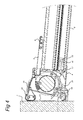
- Figure 5 shows a cross support being supported on the lower longitudinal carrier 5.
- the lower longitudinal carrier is supported on the columns.
- the lower longitudinal support 5 is a substantially U-shaped profile with a first, longer leg 24 and an opposite-lying second, shorter leg 25 on which shorter leg the underside of the cross support rests.
- a drainage profile present in the cross support opens out above the top edge of the shorter leg 5 and water and the like can flow away without hindrance in the gutter, formed within the U-shaped profile, and can be removed via the columns 3.
- the connection between the lower longitudinal support and the cross support 6 is established here by means of a hinge 32. It will be understood that any other conceivable construction can be applied.
- the longer leg 24 is constructed as hollow and a strengthening profile 26 is present therein.
- the strengthening profile can have any other rigidity-imparting shape, such as a C, an I or an H.
- the profile is preferably made from steel.
- a strength increase of this type can also be achieved by providing the lower longitudinal support in any manner with additional profiles, if, for example, said support is manufactured by extrusion. This depends on the requirements imposed by both the weight of the cross supports, i.e. the depth of the building extension, and the length of the building extension, i.e. the distance between the columns 3.
- Fastening of the column 3 to the lower longitudinal support may comprise a construction known in the prior art, and is achieved in the present example embodiment in that a recess 33 is present in column 3, extending over the entire height thereof, and is subsequently closed off by a covering strip 34 (see also Figure 1 ).
- An endplate 35 is fastened to the crosscut end of the column 3 and this endplate 35 is provided with an opening 36 for the insertion of a bolt 37 for fastening to the lower longitudinal support.
- the cross support can be brought to rest directly on the columns.
- an auxiliary longitudinal support is then mounted to the underside of the cross supports, which auxiliary longitudinal support is then supported on the columns.
- the lower longitudinal support is then constructed as a rigid drainage gutter.
- the columns can, for example, be positioned more or less inwards, so that a cross support or an end cross support respectively is supported on the columns.
- the higher longitudinal support is provided with a cloth roll 15, from which the cloth 8 can be unrolled.
- An electric motor (not shown) can be present to drive said roll.
- the cloth roll 15 is located in a gutter 39, in which rainwater and contaminants can be collected. This gutter is connected in a manner not shown in detail to the previously described drainage channel 28 of the cross supports.
- the front end of the cloth 8 is provided with a front strip 23, and this front strip 23 is connected to carriages 9 which are movable over the upper side of the cross supports 6.
- Each cross support 6 can be provided with a carriage of this type. Details of the connection of the front strip 23 to the carriage 9 are shown in Figure 6 . This shows that a securing lip 27 is present, by means of which, on the one hand the connection of the front strip 23 with the carriage 9 can be implemented by hooking in, but, on the other hand it is prevented that the front strip 23 moves out of the carriage 9 concerned by wafting up.
- a line or cable 22 is mounted (see Figure 5 ), which is connected via a reversing roller 19 and a number of further rollers 20 to a gas spring 21.
- a line or cable 22 will be mounted for only some carriages 9, for example 2 or 3 carriages. All carriages 9 can of course also be provided with such a line or cable 22.
- the line 22 and therefore the front strip 23 of the cloth 8 are always held taut, irrespective of the position thereof on the roof, i.e. irrespective of the extent of covering of the glass supports or glass panes 7.
- a gas spring a construction with different types of springs or an otherwise arranged construction can be used.
- the building extension is fastened to the facade by first fastening the auxiliary support 10 to the facade. Since the auxiliary support 10 is formed by a profile which is easily deformable in the longitudinal direction, this auxiliary support can follow the deviations in the straight surface in the facade.
- a fastening profile 11 which is movable over a limited path is then mounted to the auxiliary support 10.
- the fastening profile is provided with one or more protrusions 29 over the entire length of the auxiliary support 10 over which the fastening profile 11 can be moved.
- the facade comprises irregularities and, due to the deformation in the longitudinal direction of the auxiliary support against the facade, the irregularities are accommodated, whereas the fastening profile remains more or less straight.
- the fastening profile 11 may also consist of separate parts, which are mounted separately onto the auxiliary support 10.
- the fastening profile 11 is then moved over the auxiliary support 10 in order to align the profile and compensate for the irregularities in the surface of the facade. As a result, a straight fastening area is created for the higher longitudinal support.
- the higher longitudinal support 4 is connected to the fastening profile 11 by means of a fastening element 14 provided on the higher longitudinal support 4 and which cooperates with the fastening profile.
- the connection of the higher longitudinal support 4 to the fastening profile preferably comprises the mounting in a first mounting position of a protrusion provided on the fastening element 14 in a receptacle cavity 13 provided in the fastening profile 11, preferably over the entire length of the fastening profile, and then the movement of the higher longitudinal support to a second end position or operating position in order to lock the protrusion into the receptacle cavity, wherein the mounting position differs from the operating position.
- the higher longitudinal support can also be provided with a receptacle cavity 13 and the fastening profile can be provided with a protrusion 14.
- the fastening is then effected by moving the receptacle cavity 13 towards the protrusion 14 in such a way that the receptacle cavity 13 accommodates the protrusion.
- the higher longitudinal support is then moved from this first mounting position to an end position in order to lock the protrusion in the receptacle cavity.
- At least two cross supports 6 are fastened to the higher longitudinal support 4. More than two cross supports 6 are preferably mounted, so that panels can be accommodated in the space between the longitudinal supports and the cross supports.
- the lower longitudinal support 5 is attached to a free end of the cross supports 6.
- the building extension is then supported on at least one substantially vertically placed column 3.
- the building extension is preferably supported on two columns 3.
- the columns can support the building extension in the case of the lower longitudinal support on the ends thereof or at a distance from the ends of the longitudinal supports and/or the cross supports.
- the fastening profile 11 is preferably fastened in relation to the auxiliary support 10 by means of a fixing means 31.
- the fixing means may comprise either glue or screws, or a combination of both.
- Rights are expressly requested for the separate measures described in the subclaims without combination with the independent claims. Rights are thus requested for the fastening of the higher longitudinal support to the cross support by means of a lock without the application of the features described in claim 1. The same applies to the construction of the lower longitudinal support, the mounting of a strengthening profile herein, the use of a cloth with a cloth roll and the guiding of the cloth. Rights are requested for all of these embodiments as such, i.e. without combination with other claims.
Landscapes
- Engineering & Computer Science (AREA)
- Architecture (AREA)
- Civil Engineering (AREA)
- Structural Engineering (AREA)
- Finishing Walls (AREA)
- Greenhouses (AREA)
- Tents Or Canopies (AREA)
Priority Applications (1)
| Application Number | Priority Date | Filing Date | Title |
|---|---|---|---|
| PL13156935T PL2631383T3 (pl) | 2012-02-27 | 2013-02-27 | Dobudowa budynku |
Applications Claiming Priority (1)
| Application Number | Priority Date | Filing Date | Title |
|---|---|---|---|
| NL2008366A NL2008366C2 (nl) | 2012-02-27 | 2012-02-27 | Aanbouw. |
Publications (3)
| Publication Number | Publication Date |
|---|---|
| EP2631383A2 true EP2631383A2 (de) | 2013-08-28 |
| EP2631383A3 EP2631383A3 (de) | 2013-11-20 |
| EP2631383B1 EP2631383B1 (de) | 2020-12-16 |
Family
ID=47740871
Family Applications (1)
| Application Number | Title | Priority Date | Filing Date |
|---|---|---|---|
| EP13156935.2A Active EP2631383B1 (de) | 2012-02-27 | 2013-02-27 | Erweiterungsanbau |
Country Status (3)
| Country | Link |
|---|---|
| EP (1) | EP2631383B1 (de) |
| NL (1) | NL2008366C2 (de) |
| PL (1) | PL2631383T3 (de) |
Cited By (4)
| Publication number | Priority date | Publication date | Assignee | Title |
|---|---|---|---|---|
| EP3486397A1 (de) * | 2017-11-20 | 2019-05-22 | Erhardt Markisenbau GmbH | Markise |
| EP3851610A1 (de) * | 2020-01-14 | 2021-07-21 | Alcre (Best) B.V. | Markisensystem |
| BE1028903B1 (nl) * | 2020-12-16 | 2022-07-19 | Skylux Nv | Geëxtrudeerd gootprofiel en zelfdragend raamsamenstel |
| WO2025181779A1 (en) * | 2024-03-01 | 2025-09-04 | Insol Limited | A canopy system |
Family Cites Families (7)
| Publication number | Priority date | Publication date | Assignee | Title |
|---|---|---|---|---|
| FR2486566A1 (fr) * | 1980-07-10 | 1982-01-15 | Aluglas Pvba | Toiture en aluminium, destinee, en particulier, au recouvrement de verandas, de terrasses, de piscines de natation et d'autres constructions similaires |
| DE29500572U1 (de) * | 1995-01-16 | 1995-03-16 | Raico Bautechnik Gmbh | Wintergarten |
| GB2324815A (en) * | 1997-04-24 | 1998-11-04 | T & K Home Improvements Limite | Gutter structure for building construction |
| FR2786215B1 (fr) * | 1998-11-25 | 2001-01-12 | Profils Systemes | Faitage de veranda capable de compenser les defauts de planeite de la facade de l'immeuble sur lequel il est pose |
| CZ300981B6 (cs) * | 1999-08-24 | 2009-09-30 | Weinor Dieter Weiermann Gmbh & Co. | Sklenená strecha, zejména zimní zahrady, s vnejším zastínením |
| DE102008028174B4 (de) * | 2008-06-12 | 2018-06-28 | Dirk Raue | Sparren für ein Terrassen- und Wintergartendach, Terrassen- und Wintergartendach sowie Verfahren zum Umbau eines Terrassendachs in ein Wintergartendach |
| BE1019071A5 (nl) * | 2009-12-09 | 2012-02-07 | Kestelyn Nv | Schermconstructie voorzien van een schermkast. |
-
2012
- 2012-02-27 NL NL2008366A patent/NL2008366C2/nl active
-
2013
- 2013-02-27 PL PL13156935T patent/PL2631383T3/pl unknown
- 2013-02-27 EP EP13156935.2A patent/EP2631383B1/de active Active
Non-Patent Citations (1)
| Title |
|---|
| None |
Cited By (5)
| Publication number | Priority date | Publication date | Assignee | Title |
|---|---|---|---|---|
| EP3486397A1 (de) * | 2017-11-20 | 2019-05-22 | Erhardt Markisenbau GmbH | Markise |
| EP3851610A1 (de) * | 2020-01-14 | 2021-07-21 | Alcre (Best) B.V. | Markisensystem |
| NL2024670B1 (nl) * | 2020-01-14 | 2021-09-08 | Alcre Best B V | Zonweringssysteem. |
| BE1028903B1 (nl) * | 2020-12-16 | 2022-07-19 | Skylux Nv | Geëxtrudeerd gootprofiel en zelfdragend raamsamenstel |
| WO2025181779A1 (en) * | 2024-03-01 | 2025-09-04 | Insol Limited | A canopy system |
Also Published As
| Publication number | Publication date |
|---|---|
| EP2631383A3 (de) | 2013-11-20 |
| NL2008366C2 (nl) | 2013-08-28 |
| EP2631383B1 (de) | 2020-12-16 |
| PL2631383T3 (pl) | 2021-06-28 |
Similar Documents
| Publication | Publication Date | Title |
|---|---|---|
| US11381199B2 (en) | Solar roof system | |
| EP2631383A2 (de) | Erweiterungsanbau | |
| EP4139539B1 (de) | Terrassenüberdachung | |
| EP2906762B1 (de) | System für eine dachkonstruktion und traufe | |
| DK2472027T3 (en) | PROCEDURE FOR DETERMINING A COVERAGE ON A SKYLIGHT WINDOW | |
| EP2472029B1 (de) | Verfahren zur Befestigung eines Dichtungselementes eines Dachfensters und Dichtungssystem für ein Dachfenster | |
| US9294032B2 (en) | Modular roof solar panel for conventional roof and roofing integration | |
| KR101013016B1 (ko) | 외벽 시공 구조 | |
| EP2851483B1 (de) | Überdachungskonstruktion | |
| EP3779089B1 (de) | Dachfensterrahmen zum einbau in oder auf einem dach eines gebäudes, system mit einem dachfenster und verfahren zur befestigung eines dachfensterrahmens | |
| KR102022612B1 (ko) | 조립식 온실 및 이의 시공방법 | |
| DE102014001636B4 (de) | Wandaufbau in Verbindung mit einem Tür- oder Fensterrahmen und eine energieeffiziente Einbauanordnung mit einem Kastenelement | |
| DE20110896U1 (de) | Auflageleiste für Fassadenelemente und Anordnung von Fassadenelementen | |
| JP5396107B2 (ja) | 屋根上パネル設置用屋根瓦及び屋根上パネルの設置方法 | |
| EP3779093B1 (de) | Ein dachfenster | |
| EP3892787A1 (de) | Verschiebbare veranda mit selbstentleerendem dach | |
| JP4031417B2 (ja) | グレーチング装置、およびサッシ窓 | |
| CN220704958U (zh) | 一种无龙骨式玻璃雨棚结构 | |
| EP4414517B1 (de) | Sonnensegel mit markise | |
| AT14227U1 (de) | Aufnahmevorrichtung für eine Behangeinrichtung | |
| EP2333193B1 (de) | Überdachung | |
| CA2832861C (en) | Modular roof solar panel for conventional sloping roof and roofing integration | |
| JPH0712523Y2 (ja) | 庇 | |
| EP2345771A2 (de) | Anbringung eines Behangs in eine Markise | |
| CZ36503U1 (cs) | Pilíř zejména pro přístřešky |
Legal Events
| Date | Code | Title | Description |
|---|---|---|---|
| PUAI | Public reference made under article 153(3) epc to a published international application that has entered the european phase |
Free format text: ORIGINAL CODE: 0009012 |
|
| AK | Designated contracting states |
Kind code of ref document: A2 Designated state(s): AL AT BE BG CH CY CZ DE DK EE ES FI FR GB GR HR HU IE IS IT LI LT LU LV MC MK MT NL NO PL PT RO RS SE SI SK SM TR |
|
| AX | Request for extension of the european patent |
Extension state: BA ME |
|
| PUAL | Search report despatched |
Free format text: ORIGINAL CODE: 0009013 |
|
| AK | Designated contracting states |
Kind code of ref document: A3 Designated state(s): AL AT BE BG CH CY CZ DE DK EE ES FI FR GB GR HR HU IE IS IT LI LT LU LV MC MK MT NL NO PL PT RO RS SE SI SK SM TR |
|
| AX | Request for extension of the european patent |
Extension state: BA ME |
|
| RIC1 | Information provided on ipc code assigned before grant |
Ipc: E04F 10/06 20060101ALI20131016BHEP Ipc: E04D 13/064 20060101ALI20131016BHEP Ipc: E04F 10/00 20060101AFI20131016BHEP Ipc: E04D 3/08 20060101ALI20131016BHEP |
|
| 17P | Request for examination filed |
Effective date: 20140520 |
|
| RBV | Designated contracting states (corrected) |
Designated state(s): AL AT BE BG CH CY CZ DE DK EE ES FI FR GB GR HR HU IE IS IT LI LT LU LV MC MK MT NL NO PL PT RO RS SE SI SK SM TR |
|
| 17Q | First examination report despatched |
Effective date: 20160906 |
|
| STAA | Information on the status of an ep patent application or granted ep patent |
Free format text: STATUS: EXAMINATION IS IN PROGRESS |
|
| GRAP | Despatch of communication of intention to grant a patent |
Free format text: ORIGINAL CODE: EPIDOSNIGR1 |
|
| STAA | Information on the status of an ep patent application or granted ep patent |
Free format text: STATUS: GRANT OF PATENT IS INTENDED |
|
| INTG | Intention to grant announced |
Effective date: 20200731 |
|
| RIN1 | Information on inventor provided before grant (corrected) |
Inventor name: WOLTERS, THEODORUS BERNARDUS Inventor name: STOEL, FOKKE Inventor name: HOOGHOUDT, MARIJN JAAP ANTON MARIA Inventor name: DIRKSE, MAARTEN THOMAS |
|
| GRAS | Grant fee paid |
Free format text: ORIGINAL CODE: EPIDOSNIGR3 |
|
| GRAA | (expected) grant |
Free format text: ORIGINAL CODE: 0009210 |
|
| STAA | Information on the status of an ep patent application or granted ep patent |
Free format text: STATUS: THE PATENT HAS BEEN GRANTED |
|
| AK | Designated contracting states |
Kind code of ref document: B1 Designated state(s): AL AT BE BG CH CY CZ DE DK EE ES FI FR GB GR HR HU IE IS IT LI LT LU LV MC MK MT NL NO PL PT RO RS SE SI SK SM TR |
|
| REG | Reference to a national code |
Ref country code: GB Ref legal event code: FG4D |
|
| REG | Reference to a national code |
Ref country code: DE Ref legal event code: R096 Ref document number: 602013074712 Country of ref document: DE |
|
| REG | Reference to a national code |
Ref country code: IE Ref legal event code: FG4D |
|
| REG | Reference to a national code |
Ref country code: AT Ref legal event code: REF Ref document number: 1345728 Country of ref document: AT Kind code of ref document: T Effective date: 20210115 |
|
| REG | Reference to a national code |
Ref country code: NL Ref legal event code: FP |
|
| PG25 | Lapsed in a contracting state [announced via postgrant information from national office to epo] |
Ref country code: FI Free format text: LAPSE BECAUSE OF FAILURE TO SUBMIT A TRANSLATION OF THE DESCRIPTION OR TO PAY THE FEE WITHIN THE PRESCRIBED TIME-LIMIT Effective date: 20201216 Ref country code: RS Free format text: LAPSE BECAUSE OF FAILURE TO SUBMIT A TRANSLATION OF THE DESCRIPTION OR TO PAY THE FEE WITHIN THE PRESCRIBED TIME-LIMIT Effective date: 20201216 Ref country code: NO Free format text: LAPSE BECAUSE OF FAILURE TO SUBMIT A TRANSLATION OF THE DESCRIPTION OR TO PAY THE FEE WITHIN THE PRESCRIBED TIME-LIMIT Effective date: 20210316 Ref country code: GR Free format text: LAPSE BECAUSE OF FAILURE TO SUBMIT A TRANSLATION OF THE DESCRIPTION OR TO PAY THE FEE WITHIN THE PRESCRIBED TIME-LIMIT Effective date: 20210317 |
|
| PG25 | Lapsed in a contracting state [announced via postgrant information from national office to epo] |
Ref country code: SE Free format text: LAPSE BECAUSE OF FAILURE TO SUBMIT A TRANSLATION OF THE DESCRIPTION OR TO PAY THE FEE WITHIN THE PRESCRIBED TIME-LIMIT Effective date: 20201216 Ref country code: LV Free format text: LAPSE BECAUSE OF FAILURE TO SUBMIT A TRANSLATION OF THE DESCRIPTION OR TO PAY THE FEE WITHIN THE PRESCRIBED TIME-LIMIT Effective date: 20201216 Ref country code: BG Free format text: LAPSE BECAUSE OF FAILURE TO SUBMIT A TRANSLATION OF THE DESCRIPTION OR TO PAY THE FEE WITHIN THE PRESCRIBED TIME-LIMIT Effective date: 20210316 |
|
| PG25 | Lapsed in a contracting state [announced via postgrant information from national office to epo] |
Ref country code: HR Free format text: LAPSE BECAUSE OF FAILURE TO SUBMIT A TRANSLATION OF THE DESCRIPTION OR TO PAY THE FEE WITHIN THE PRESCRIBED TIME-LIMIT Effective date: 20201216 |
|
| REG | Reference to a national code |
Ref country code: LT Ref legal event code: MG9D |
|
| PG25 | Lapsed in a contracting state [announced via postgrant information from national office to epo] |
Ref country code: PT Free format text: LAPSE BECAUSE OF FAILURE TO SUBMIT A TRANSLATION OF THE DESCRIPTION OR TO PAY THE FEE WITHIN THE PRESCRIBED TIME-LIMIT Effective date: 20210416 Ref country code: RO Free format text: LAPSE BECAUSE OF FAILURE TO SUBMIT A TRANSLATION OF THE DESCRIPTION OR TO PAY THE FEE WITHIN THE PRESCRIBED TIME-LIMIT Effective date: 20201216 Ref country code: SK Free format text: LAPSE BECAUSE OF FAILURE TO SUBMIT A TRANSLATION OF THE DESCRIPTION OR TO PAY THE FEE WITHIN THE PRESCRIBED TIME-LIMIT Effective date: 20201216 Ref country code: LT Free format text: LAPSE BECAUSE OF FAILURE TO SUBMIT A TRANSLATION OF THE DESCRIPTION OR TO PAY THE FEE WITHIN THE PRESCRIBED TIME-LIMIT Effective date: 20201216 Ref country code: SM Free format text: LAPSE BECAUSE OF FAILURE TO SUBMIT A TRANSLATION OF THE DESCRIPTION OR TO PAY THE FEE WITHIN THE PRESCRIBED TIME-LIMIT Effective date: 20201216 Ref country code: EE Free format text: LAPSE BECAUSE OF FAILURE TO SUBMIT A TRANSLATION OF THE DESCRIPTION OR TO PAY THE FEE WITHIN THE PRESCRIBED TIME-LIMIT Effective date: 20201216 |
|
| REG | Reference to a national code |
Ref country code: AT Ref legal event code: UEP Ref document number: 1345728 Country of ref document: AT Kind code of ref document: T Effective date: 20201216 |
|
| REG | Reference to a national code |
Ref country code: DE Ref legal event code: R097 Ref document number: 602013074712 Country of ref document: DE |
|
| PG25 | Lapsed in a contracting state [announced via postgrant information from national office to epo] |
Ref country code: MC Free format text: LAPSE BECAUSE OF FAILURE TO SUBMIT A TRANSLATION OF THE DESCRIPTION OR TO PAY THE FEE WITHIN THE PRESCRIBED TIME-LIMIT Effective date: 20201216 Ref country code: IS Free format text: LAPSE BECAUSE OF FAILURE TO SUBMIT A TRANSLATION OF THE DESCRIPTION OR TO PAY THE FEE WITHIN THE PRESCRIBED TIME-LIMIT Effective date: 20210416 |
|
| PLBE | No opposition filed within time limit |
Free format text: ORIGINAL CODE: 0009261 |
|
| STAA | Information on the status of an ep patent application or granted ep patent |
Free format text: STATUS: NO OPPOSITION FILED WITHIN TIME LIMIT |
|
| PG25 | Lapsed in a contracting state [announced via postgrant information from national office to epo] |
Ref country code: LI Free format text: LAPSE BECAUSE OF NON-PAYMENT OF DUE FEES Effective date: 20210228 Ref country code: LU Free format text: LAPSE BECAUSE OF NON-PAYMENT OF DUE FEES Effective date: 20210227 Ref country code: CH Free format text: LAPSE BECAUSE OF NON-PAYMENT OF DUE FEES Effective date: 20210228 Ref country code: AL Free format text: LAPSE BECAUSE OF FAILURE TO SUBMIT A TRANSLATION OF THE DESCRIPTION OR TO PAY THE FEE WITHIN THE PRESCRIBED TIME-LIMIT Effective date: 20201216 Ref country code: IT Free format text: LAPSE BECAUSE OF FAILURE TO SUBMIT A TRANSLATION OF THE DESCRIPTION OR TO PAY THE FEE WITHIN THE PRESCRIBED TIME-LIMIT Effective date: 20201216 |
|
| 26N | No opposition filed |
Effective date: 20210917 |
|
| GBPC | Gb: european patent ceased through non-payment of renewal fee |
Effective date: 20210316 |
|
| PG25 | Lapsed in a contracting state [announced via postgrant information from national office to epo] |
Ref country code: DK Free format text: LAPSE BECAUSE OF FAILURE TO SUBMIT A TRANSLATION OF THE DESCRIPTION OR TO PAY THE FEE WITHIN THE PRESCRIBED TIME-LIMIT Effective date: 20201216 Ref country code: ES Free format text: LAPSE BECAUSE OF FAILURE TO SUBMIT A TRANSLATION OF THE DESCRIPTION OR TO PAY THE FEE WITHIN THE PRESCRIBED TIME-LIMIT Effective date: 20201216 |
|
| PG25 | Lapsed in a contracting state [announced via postgrant information from national office to epo] |
Ref country code: IE Free format text: LAPSE BECAUSE OF NON-PAYMENT OF DUE FEES Effective date: 20210227 Ref country code: GB Free format text: LAPSE BECAUSE OF NON-PAYMENT OF DUE FEES Effective date: 20210316 Ref country code: FR Free format text: LAPSE BECAUSE OF NON-PAYMENT OF DUE FEES Effective date: 20210228 |
|
| PG25 | Lapsed in a contracting state [announced via postgrant information from national office to epo] |
Ref country code: SI Free format text: LAPSE BECAUSE OF FAILURE TO SUBMIT A TRANSLATION OF THE DESCRIPTION OR TO PAY THE FEE WITHIN THE PRESCRIBED TIME-LIMIT Effective date: 20201216 |
|
| PG25 | Lapsed in a contracting state [announced via postgrant information from national office to epo] |
Ref country code: IS Free format text: LAPSE BECAUSE OF FAILURE TO SUBMIT A TRANSLATION OF THE DESCRIPTION OR TO PAY THE FEE WITHIN THE PRESCRIBED TIME-LIMIT Effective date: 20210416 |
|
| PG25 | Lapsed in a contracting state [announced via postgrant information from national office to epo] |
Ref country code: HU Free format text: LAPSE BECAUSE OF FAILURE TO SUBMIT A TRANSLATION OF THE DESCRIPTION OR TO PAY THE FEE WITHIN THE PRESCRIBED TIME-LIMIT; INVALID AB INITIO Effective date: 20130227 |
|
| P01 | Opt-out of the competence of the unified patent court (upc) registered |
Effective date: 20230518 |
|
| PG25 | Lapsed in a contracting state [announced via postgrant information from national office to epo] |
Ref country code: CY Free format text: LAPSE BECAUSE OF FAILURE TO SUBMIT A TRANSLATION OF THE DESCRIPTION OR TO PAY THE FEE WITHIN THE PRESCRIBED TIME-LIMIT Effective date: 20201216 |
|
| PG25 | Lapsed in a contracting state [announced via postgrant information from national office to epo] |
Ref country code: MK Free format text: LAPSE BECAUSE OF FAILURE TO SUBMIT A TRANSLATION OF THE DESCRIPTION OR TO PAY THE FEE WITHIN THE PRESCRIBED TIME-LIMIT Effective date: 20201216 |
|
| PG25 | Lapsed in a contracting state [announced via postgrant information from national office to epo] |
Ref country code: MT Free format text: LAPSE BECAUSE OF FAILURE TO SUBMIT A TRANSLATION OF THE DESCRIPTION OR TO PAY THE FEE WITHIN THE PRESCRIBED TIME-LIMIT Effective date: 20201216 |
|
| PG25 | Lapsed in a contracting state [announced via postgrant information from national office to epo] |
Ref country code: TR Free format text: LAPSE BECAUSE OF FAILURE TO SUBMIT A TRANSLATION OF THE DESCRIPTION OR TO PAY THE FEE WITHIN THE PRESCRIBED TIME-LIMIT Effective date: 20201216 |
|
| PGFP | Annual fee paid to national office [announced via postgrant information from national office to epo] |
Ref country code: NL Payment date: 20260209 Year of fee payment: 14 |
|
| PGFP | Annual fee paid to national office [announced via postgrant information from national office to epo] |
Ref country code: DE Payment date: 20260220 Year of fee payment: 14 |
|
| PGFP | Annual fee paid to national office [announced via postgrant information from national office to epo] |
Ref country code: AT Payment date: 20260218 Year of fee payment: 14 |
|
| PGFP | Annual fee paid to national office [announced via postgrant information from national office to epo] |
Ref country code: BE Payment date: 20260220 Year of fee payment: 14 |
|
| PGFP | Annual fee paid to national office [announced via postgrant information from national office to epo] |
Ref country code: CZ Payment date: 20260223 Year of fee payment: 14 |
|
| PGFP | Annual fee paid to national office [announced via postgrant information from national office to epo] |
Ref country code: PL Payment date: 20260213 Year of fee payment: 14 |