EP2630890B1 - Panneau de bagage avec poignée intégrée et bagages - Google Patents
Panneau de bagage avec poignée intégrée et bagages Download PDFInfo
- Publication number
- EP2630890B1 EP2630890B1 EP13002141.3A EP13002141A EP2630890B1 EP 2630890 B1 EP2630890 B1 EP 2630890B1 EP 13002141 A EP13002141 A EP 13002141A EP 2630890 B1 EP2630890 B1 EP 2630890B1
- Authority
- EP
- European Patent Office
- Prior art keywords
- luggage
- textile
- textile body
- panel
- panel according
- Prior art date
- Legal status (The legal status is an assumption and is not a legal conclusion. Google has not performed a legal analysis and makes no representation as to the accuracy of the status listed.)
- Active
Links
- 239000004753 textile Substances 0.000 claims description 158
- 239000000463 material Substances 0.000 claims description 49
- 239000004744 fabric Substances 0.000 claims description 23
- 239000004677 Nylon Substances 0.000 claims description 3
- 229920001778 nylon Polymers 0.000 claims description 3
- 229920000728 polyester Polymers 0.000 claims description 3
- 238000010276 construction Methods 0.000 description 18
- 238000000034 method Methods 0.000 description 10
- 239000006260 foam Substances 0.000 description 9
- 239000005038 ethylene vinyl acetate Substances 0.000 description 6
- 229910000831 Steel Inorganic materials 0.000 description 5
- DQXBYHZEEUGOBF-UHFFFAOYSA-N but-3-enoic acid;ethene Chemical compound C=C.OC(=O)CC=C DQXBYHZEEUGOBF-UHFFFAOYSA-N 0.000 description 5
- 229920001200 poly(ethylene-vinyl acetate) Polymers 0.000 description 5
- 239000010959 steel Substances 0.000 description 5
- 238000012856 packing Methods 0.000 description 3
- 229920000642 polymer Polymers 0.000 description 3
- 240000008564 Boehmeria nivea Species 0.000 description 2
- 229920001903 high density polyethylene Polymers 0.000 description 2
- 239000004700 high-density polyethylene Substances 0.000 description 2
- 239000010985 leather Substances 0.000 description 2
- -1 polypropylene Polymers 0.000 description 2
- 230000002787 reinforcement Effects 0.000 description 2
- 229920000049 Carbon (fiber) Polymers 0.000 description 1
- 239000004698 Polyethylene Substances 0.000 description 1
- 239000004743 Polypropylene Substances 0.000 description 1
- 238000005299 abrasion Methods 0.000 description 1
- 238000004026 adhesive bonding Methods 0.000 description 1
- XAGFODPZIPBFFR-UHFFFAOYSA-N aluminium Chemical compound [Al] XAGFODPZIPBFFR-UHFFFAOYSA-N 0.000 description 1
- 229910052782 aluminium Inorganic materials 0.000 description 1
- 239000011230 binding agent Substances 0.000 description 1
- 239000004917 carbon fiber Substances 0.000 description 1
- 239000011111 cardboard Substances 0.000 description 1
- 230000006835 compression Effects 0.000 description 1
- 238000007906 compression Methods 0.000 description 1
- 230000001419 dependent effect Effects 0.000 description 1
- 238000001125 extrusion Methods 0.000 description 1
- 238000002347 injection Methods 0.000 description 1
- 239000007924 injection Substances 0.000 description 1
- 238000001746 injection moulding Methods 0.000 description 1
- 230000007246 mechanism Effects 0.000 description 1
- VNWKTOKETHGBQD-UHFFFAOYSA-N methane Chemical compound C VNWKTOKETHGBQD-UHFFFAOYSA-N 0.000 description 1
- 238000012986 modification Methods 0.000 description 1
- 230000004048 modification Effects 0.000 description 1
- 229920000573 polyethylene Polymers 0.000 description 1
- 229920001155 polypropylene Polymers 0.000 description 1
- 239000004800 polyvinyl chloride Substances 0.000 description 1
- 238000009958 sewing Methods 0.000 description 1
Images


Classifications
-
- A—HUMAN NECESSITIES
- A45—HAND OR TRAVELLING ARTICLES
- A45C—PURSES; LUGGAGE; HAND CARRIED BAGS
- A45C13/00—Details; Accessories
- A45C13/26—Special adaptations of handles
-
- A—HUMAN NECESSITIES
- A45—HAND OR TRAVELLING ARTICLES
- A45C—PURSES; LUGGAGE; HAND CARRIED BAGS
- A45C5/00—Rigid or semi-rigid luggage
- A45C5/14—Rigid or semi-rigid luggage with built-in rolling means
Definitions
- the field of invention generally relates to luggage.
- Luggage cases or the like may include two or more wheels mounted on or next to the bottom panel of such luggage cases to facilitate transportation of the luggage cases by dragging or pushing the luggage cases. Even when such luggage cases include this convenient wheeling system, it may be necessary to lift or carry the case by hand. For example, placing the luggage case in the trunk or passenger compartment of a vehicle or transferring the luggage to or from a luggage carousel in an airport or the like may require the luggage case to be lifted or carried. Any handles or grips for such purposes should be quite strong since each handle must support the weight of the luggage case when it is filled with a traveler's belongings. Also, for a structured soft-side luggage case, the panel to which the carry handle is attached must be sturdy enough to not significantly distort the shape of the case when the filled luggage is carried by the handle.
- a luggage wherein a two piece carrying handle formed by flaps being Integral with one major side surface thereof is know from US 4 298 104.
- a binder strap system for bags or the like is known from US 200310099503A1 .
- a luggage case may include a panel with a carry handle integrated therewith.
- the panel may include a generally flat sheet of flexible laminar body material that constitutes the bulk of the outside surface of the soft-side luggage case.
- the luggage case may further include a resilient hoop positioned around the perimeter of the panel.
- a resilient hoop may be firmly attached to the flexible laminar body material. In some embodiments, this body material is firmly attached to at least a majority of the hoop.
- Two side portions of the flat sheet may be reduced in dimension to form a handle grip located generally in the center of the sheet.
- Beneath this grip may be a second sheet of a flexible laminar material, preferably also of body material, affixed at its edges to the remaining portions of the perimeter wire hoop exposed by the narrowed portion of laminar body material that defines the handle grip.
- a luggage case may include a first panel.
- the first panel may include a perimeter edge.
- the first panel may define at least a portion of an outer surface of the luggage.
- the first panel may include a first textile body.
- the first textile body may define at least a portion of an outer surface of the first panel.
- the first textile body may further define at least a portion of the perimeter edge of the first panel.
- the first textile body may include a grip portion defining a grip for a carry handle.
- Described herein are methods for making structured but essentially soft-sided luggage cases, and products created using such methods. These cases are usually formed from textile panels, leather panels or simulated leather panels. These cases may include other components, such as frames, boards, and so on, that are intended to hold the otherwise flimsy panels in a generally flat rectangular shape to form a luggage case with an overall parallelepiped shape. More particularly, described herein is a particularly lightweight construction for those panels that also serves to mount a carry handle for manually carrying or towing the luggage case during travel, etc.
- the construction methods include making rectangular, or other shaped, panels with integrated carrying handles for luggage cases, such as upright or spinner type cases, or the like (e.g., duffel bags, backpacks, and so on) where one mode for transporting the luggage case is to drag or push the luggage case on two or more wheels mounted on or next to the bottom panel of such luggage case.
- luggage cases such as upright or spinner type cases, or the like (e.g., duffel bags, backpacks, and so on) where one mode for transporting the luggage case is to drag or push the luggage case on two or more wheels mounted on or next to the bottom panel of such luggage case.
- minimal or no rigid stiffening structures may be used to reduce to weight of the style luggage case.
- Such a light construction may contribute to the overall light weight of the empty case, while demonstrating that the case is robust and dimensionally stable.
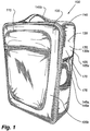
- a luggage case 100 may include one or more sides 105.
- the luggage case may include six sides 105a-c (e.g., top, bottom, left, right, front and back sides). Other embodiments of the luggage case 100 may include more or less than six sides.
- the sides 105 of the luggage case 100 may define a main packing compartment.
- Each side 105 may have a generally rectangular shape to form a generally parallelepiped luggage case 100.
- the sides 105 may have other shapes to define a luggage case 100 with a desired shape other than generally parallelepiped.
- the luggage case 100 may further includes wheels 110, glides, edge piping 115 to help protect the outer surface of the luggage from scuffs and abrasions, and a main door 120 with a perimeter zipper 125 for access to at least the main packing compartment.
- Each side 105 of the luggage case 100 may be formed using one or more panels 130.
- each side 105 of the luggage case 100 may be formed using a single panel 130.
- two or more panels 130 may be used to form a side 105 of the luggage case 100.
- At least some of the panels 130 forming the sides 105 of the luggage case 100 may define at least a portion of the outer surface 135 of the luggage case 100.
- the side and top panels 130a,b define a portion of the outer surface 135 of the luggage case 100.
- At least some of the panels 130 may be joined to an adjacent panel 130 proximate a perimeter edge 140 of the panel 130.
- a first panel 130a e.g., a side panel
- a second panel 130b e.g., a top panel
- a perimeter edge 140 of the first panel 130a e.g., the upper edge of the side panel
- the luggage case 100 may further include carry handles 145 integrally joined with the one or more panels 130 that define the sides 105 of the luggage case 100.
- the side panel 105a and the top panel 105b of the luggage case may each include a carry handle 145a,b integrally joined with its respective pane! 130a,b. While the carry handles 145 are shown as integrally joined with the top and side panels 130, a carry handle 145 may be integrally joined with any panel 130 defining a side 105 of the luggage case 100.
- the side panel 130a may include perimeter edge 140 to which one or more other panels 130 may be attached. While the other panels 130 are typically attached to the side panel 130a by sewing, any suitable connection method may be used to join the panels 130 together.
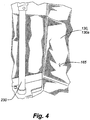
- a reinforcement assemblage may be positioned proximate the perimeter edge 140 of the side panel.
- the reinforcement assemblage may include an edge beading 150 and a generally rectangular frame or hoop 155 of a resilient, tough steel wire or similar material.
- the hoop 155 may be resilient, flexible and resistant to compression but may also be bendable and flexible, especially along its longer straight sides unless constrained.
- the hoop 155 may be positioned within a substantially enclosed space defined by the edge beading.
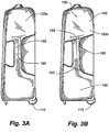
- the side panel 130a may include the perimeter edge 140, an outer surface 160 and an inner surface 165.
- the perimeter edge 140 may define a rectangular shape, or any other desired shape.
- the outer surface 160 is constructed using a first textile body 170 and a second textile body 175.
- the first and second textile bodies 170,175 may be formed from a robust woven textile, such as nylon, polyester, Ramie or the like.
- the first textile body 170 may be generally rectangular in shape, or any other shape that generally matches at least a portion of the shape defined by the perimeter 140 edge of the side panel 130a.
- a central or grip portion 180 of the first textile body 170 may define a relatively narrow band of material between first and second portions 185,190 of the first textile body 170.
- the relatively narrow band of material defines the grip for the carry handle 145a.
- the first and second portions 185, 190 may be formed at end or outer portions of the first textile body 170.
- the central or grip portion 180 may be smoothly and integrally joined to the first and second portions 185,190 of the first textile body 170 by way of curved edges.
- Each first and second portion 185,190 of the first textile body 170 widened from a relative narrow dimension proximate the central or grip portion 180 to the full width dimension of the generally rectangular side panel 130a.
- the central or grip portion 180 of the first textile body 170 defines a handle grip with a longitudinal axis that is relatively transverse to an edge defining the width of the first and second portions and/or the panel.
- a handle grip may have a longitudinal axis that is positioned at an angle relative to the edge defining the width of the first and second portions and/or the panel.
- Such as configuration is shown, for example, in Figure 10 .
- the foregoing examples are merely illustrative of how the handle may be positioned relative to the first and second portions 185,190 of the first textile body 170 and/or the side panel 130a.
- Other configurations of the handle relative to the first and second portions 130a,b of the first textile body and/or the panel may be defined in the central or grip portion 180 of the first textile body 170 so long as the handle is formed from a first textile body 170 that defines at least a portion of the outer surface 135 of the side panel 130a.
- the first textile body 170 in some embodiments may be made from a single piece of textile material.
- the central or grip portion 180 may be formed by cutting material within the central or grip portion 180 of the single piece of textile material to define the narrow band of material.
- the cut edges created in the central or grip portion 180 may be finished either by folding the edges or by applying an edge beading or trim.
- the first, second and central (or grip) portions 180,185,190 could be defined when creating the piece of textile material used for the first textile body 170.
- the first textile body 170 may formed using two or more pieces of textile material.
- two pieces of textile material joined by a seam 195 positioned proximate a centerline of the central or grip portion 180 may be utilized to form the first textile body 170.
- Such a construction for the first textile body 170 may result in an overall saving in textile material compared to forming the first textile body 170 from a single piece of textile material.
- three pieces of textile material may be joined by seams 195 to form the first textile body 170.
- One piece may be used to form the central or grip portion 180 of the first textile body, and the other two pieces may be used to form the first and second portions 185, 190 of the first textile body 170.
- Such a construction may result in further material savings compared to using a single piece of material and also would permit the use of a contrasting color or texture choice for the central or grip portion 180 of the first textile body 170.
- Such a contrasting material choice may have aesthetic and functional advantages.
- first textile body 170 may be formed, and are not intended to limit how the first textile body 170 may be formed. Further, while described as being formed using one, two or three pieces of textile material, any number of pieces of textile material may be use to created the first textile body 170.
- the first and second portions 185,190 of the first textile body 170 may be joined to the edge beading 150.
- the first and second portions 185,190 may be joined to the edge beading 150 by stitching the first and second portions 185,190 along at least a portion of their edges to the edge beading 150, or by using any other suitable connection method, including, but not limited to, adhering or bonding the first and second portions 185,190 to the edge beading 150.
- This joining of the first and second portions 185,190 of the first textile body 170 to the edge beading 150 functions to operatively connect the first textile body 170 with the hoop 155.
- the second textile body 175 may be generally square or rectangular in shape.
- the second textile body 175 is positioned underneath the central or grip portion 180 of the first textile body 170.
- the second textile body 175 may include two edges, which may be referred to as first and second edges 200, 205, that each span the width of the first and second portions 185,190 of the first textile body 170, and two other edges, which may be referred to as third and fourth edges 210, 215, that span at least the length of the central or grip portion 180 of the first textile body 170.
- the third and fourth edges 210, 215 may end proximate the perimeter edge 140 of the side panel 130a.
- the first and second edges 200, 205 may be joined to the first textile body 170 by a suitable connection method, such as stitching or bonding.
- the third and fourth edges 210, 215 may be joined to the perimeter edge 140 of the panel 130a by a suitable connection method, such as stitching or bonding.
- the first and second textile bodies 170,175 may define substantially the entire outer surface 135 of the side panel 130a. Portions of the edges of the first and second textile bodies 170,175 may also collectively define the perimeter edge 140 of the side panel 130a.
- the inner surface 165 of the panel may be formed using a lining material 220.
- This lining material 220 may be a textile material that is fairly light and smooth to give a pleasing interior texture and finished look to the luggage case 100.
- the lining material 220 is not necessary from a structural standpoint. Thus, the lining material 220 may be omitted, if desired.
- the first and second textile bodies 170,175 may define the inner surface 165 of the side panel 130a.
- the lifting force from the handle grip may transferred by way of the first and second portions 185, 190 of the first textile body 170 to the perimeter edge 140 of the side panel 130a.
- the lifting force may result in horizontal and vertical forces being imposed on the perimeter edge 140 of the side panel 130a.
- the horizontal forces may generally result in compressive forces applied along the longitudinal axes of the hoop 155.
- the vertical forces may generally result in the rest of the luggage case and its contents hanging from the hoop 155.
- the hoop 155 helps to minimize the distortion of the side panel 130a with the integrated carry handle 145a.
- Both the horizontal and vertical forces applied to the hoop 155 may be relatively uniform, which may further help to minimize the distortion of the side panel 130a with the integrated carry handle 145a.
- the panels 130 that incorporate the integrated carry handle 145 are relatively light. As a result of this construction, the prospective purchaser may perceive the luggage case 100 to be strong enough to withstand the rigors of travel, while also appreciating it as being lighter than conventional luggage constructions.
- a relatively rigid material such as a polypropylene or polyethylene board
- the first textile body 170 may be joined to the relatively rigid material to transfer at least some of the forces imposed upon the carry handle 145 to the relatively rigid material.
- the first textile body 170 may be joined by mechanical fasteners 225, such as rivets, screws, staples, and so on, or by any other suitable joining method, including, but not limited to, by bonding or gluing.
- Figures 13 and 14 show schematic partial cross-section views of additional examples of possible ways to form the carry handle 145. While these views only show one edge 300 of the carry handle 145, the edge of the carry handle 145 that is distal this edge 300 may be formed in a similar manner. Thus, the following description is applicable to edge of the carry handle 145 distal the edge 300 shown in Figures 13 and 14 .
- the carry handle 145 may be formed using the first textile body 170 and a third textile body 305.
- the first textile body 170 may define a first outer surface 310, such as the upper surface, of the grip for the carry handle 145, and the third textile body 305 may define a second outer surface 315, such as the lower surface, of the grip for the carry handle 145.
- the first textile body 170 may further include first and second end portions 185,190 that define at least portions of the perimeter edge 140 of the panel 130.
- the panel 130 associated with the first textile body 170 may include the second textile body 175.
- the second textile body 175 in conjunction with the first textile body 170 may collectively define the outer surface 160 of the panel 130.
- the third textile body 305 may include a grip portion 320 to define, in conjunction with the first textile body 170, the grip of the carry handle 145.
- the grip portion 320 for the third textile body 305 may correspond to, or otherwise match in shape, the grip portion 180 of the first textile body 170.
- the third textile body 305 like the first textile body 170, may further include first and second portions (not shown) with the grip portion 320 positioned between the first and second portions.
- the first and second portions of the third textile body 305 when present, may generally correspond to, other otherwise match, the shape of the first and second portions of the first textile body 170.
- first and second portions of the third textile body 305 may extend only under a portion of the respective first and second portions 185,190 of the first textile body 170. In such embodiments, one or more edges of the first and second portions of the third textile body 305 may not extend to the perimeter edge 140 of the panel 130.
- an edge fabric 325 may be positioned along each edge 330, 335 of at least the grip portions 180, 320 of the first and third textile bodies 170, 305.
- the edge fabric 325 could also be positioned along at least portion of the edges of the first and second portions of either, or both, of the first and third textile bodies 170, 305.
- the edge fabric 325 may be configured to define a substantially enclosed space for receiving a stiffening element 340 (which may also be considered as a rigid or semi-rigid element), such as a polyvinyl chloride (PVC) pipe, a steel or carbon fiber wire, and so on.
- PVC polyvinyl chloride
- the stiffening element 340 may help to maintain the shape of the grip of the carry handle 145 defined by the first and third textile bodies 170, 305.
- the edge fabric 325 may be folded into a C- or U-shape to define the enclosed space for the stiffening element 340.
- the ends 345 of the edge fabric 325 may be positioned between the inner facing surfaces 350, 355 of the first and third textile bodies 170, 305.
- a portion of the edge fabric 325 may extend beyond the edges 330, 335 of the first and third textile bodies 170, 305. This portion may include the enclosed space that receives the optional stiffening element 340.
- the end portions of the first and third textile bodies 170, 305, proximate the edge fabric 325 may be folded into a C-or U-shape to define the curved edges 330, 335 for the first and second textile bodies 170, 305.
- the stiffening element 340 (if any) positioned within the enclosed space, and the ends 345 of the folded edge fabric 325 positioned between the inner facing surfaces 350, 355 of the first and third textile bodies 170, 305, the edge fabric 325, the first textile body 170, and the third textile body 305 may be sewn together, or otherwise suitably joined.
- the third textile body 305 and the edge fabric 325 may be formed from a robust woven textile, such as nylon, polyester, Ramie or the like.
- Figure 14 shows a handle construction similar to the construction shown in Figure 13 .
- the carry handle 145 shown in Figure 14 includes the first textile body 170, the third textile body 305, and an edge fabric 325.
- the primary difference between these two carry handles 145 arises from how the edge fabric 325 is joined to the first and third textile bodies 170, 305.
- the edge fabric 325 is folded into a C- or U-shape, similar to the edge fabric 325 in Figure 13 .
- the ends 345 of the edge fabric 325 are positioned over the outer facing surfaces 360, 365 of the first and third textile bodies 170, 305.
- edges 330, 335 of the first and third textile bodies 170, 305 are positioned between an inner facing surface 370 of the edge fabric 325. Further, unlike the construction shown in Figure 13 , the end portions of the first and third textile bodies 170, 305 are not folded (i.e., they remain straight). Once the edges 330, 335 of the first and third textile bodies 170, 305 are positioned as shown in Figure 14 , the edge fabric 325, the first textile body 170, and third textile body 305 may be sewn together, or otherwise suitably joined. While no stiffening element 340 is shown in Figure 14 , a stiffening element 340 could be positioned within the curved portion of the edge fabric 325, if desired.
- Additional materials or components may be placed between the first and third textile bodies 170, 305, if desired. These additional materials or components may be used to help maintain the shape of the carry handle 145, to provide additional structural support for the handle, or to enhance the comfort for a user.
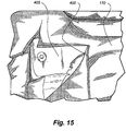
- Figures 15 and 16 show pictures of a luggage case that is cut apart to show some of the materials or components that may be positioned between the first and third textile bodies 170, 305.
- EVA foam 400 may joined to the inner facing surfaces of either, or both, of the first and third textile bodies 170, 305. The EVA foam 400 may create a more comfortable grip for a user.
- the EVA foam 400 may be joined to the first and third textile bodies 170,305 by adhering the EVA foam 400 to the textile bodies 170, 305 or by any other suitable connection method.
- the foam may be positioned between the first and third textile bodies 170, 305 without joining the foam to the textile bodies 170,305.
- a rigid or semi-rigid board 405 such as a high-density polyethylene (HDPE) board, may be positioned between the first and third textile materials 170, 305.
- the board 405 may extend from one end of the grip to the opposite end of the grip. Within the grip, the board may be shaped to correspond to the shape of the grip portions 180, 320 for the first and third textile bodies 170, 305.
- the board 405 may help to maintain the shape for the handle and/or may provide structural support for the handle.
- the board 405 may be mechanically fastened with fasteners (such as screws, rivets, and so on), or otherwise joined, to other underlying materials to maintain the relative position of the board to the first and third textile bodies 170, 305.
- a rigid or semi-rigid plate 410 such as a steel plate, may be positioned between the first and third textile materials 170, 305.
- the plate 410 may extend from one end of the grip to the opposite end of the grip.
- the plate 410 may help to maintain the shape for the handle and/or may provide structural support for the handle.
- first and third textile bodies may be positioned between the first and third textile bodies. Some or all of these materials may or may not be positioned between the first and third textile bodies. Further, other materials or components may or may not be positioned between the first and third textile bodies, such as cardboards, foams other than EVA foams, other fabrics, and so on. Further, in some embodiments, there may be no additional components or materials positioned between the first textile bodies.
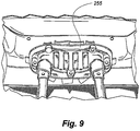
- the luggage case 100 may be constructed of materials that further enhance its lightweight impression.
- the down tubes 230 shown in Figure 8
- the bottom board 245 may be a single honeycomb polymer board. This polymer board may be attached to a monolithic wheel bracket and kick plate 250.
- the housing 255 used to hold the grip portion of the telescopic handle 240 may be a punctured wheel housing type. Such a housing 255 may result in a light luggage case since it may weigh less than the typical, more complex attachment mechanisms used in conventional luggage cases.
- a higher quality steel may be used to form the thin perimeter wire hoops 155 around the carry handle-bearing panels and around the other panels 130 of the luggage case 100. This permits the diameter of that wire to be reduced, resulting it in a further incremental weight saving.
- Other materials and constructions may also be used to make the hoop 155, such as an extruded polymer bent into the hoop shape during extrusion or in a post-forming step.
- the hoop 155 may also be made of one piece, such as by injection molding or stamping from a preformed sheet so long as the sheet panel is sufficiently stiff to resist collapse when subjected to the pulling forces from the first textile body attached to the perimeter of the stiff panel.
- the perimeter hoop could be made of different separate pieces (e.g., injection molded corners with straight pultruded sides).
- the above-described constructions may reduce the weight of the upright luggage case compared to conventionally constructed luggage cases.
- the incorporating a handle into a textile body that forms at least a portion of the outer surface of a panel may contribute to a substantial weight saving over an equivalently sized but conventionally constructed case with rigidifying perimeter or corrugated or honeycomb frame members.
- Luggage cases of the soft-side construction are perceived to be lighter than hard-side cases.
- many rigidifying elements in soft-side cases tend to add to the weight of a soft-side luggage case. This reduces its weight advantage over molded shell luggage cases.
- Using a textile body in the luggage case to form both the grip of a carry handle and a portion of the outer surface of the luggage helps to reduce the weight of the luggage.
- the textile body may be attached to a thin resilient wire hoop to resist distortion of the luggage case when it is lifted by the handle. This construction saves weight in comparison to conventional luggage case constructions.
Claims (15)
- Panneau de bagage, en particulier panneau latéral ou supérieur d'un boîtier de bagage type à paroi souple, ayant une poignée de transport intégrée, le panneau de bagage comprenant :un premier corps textile (170) qui forme au moins une section d'une surface externe du panneau, et possède au moins un bord définissant au moins une partie des bords de périmètre du panneau de bagage auxquels d'autres panneaux formant un boîtier de bagage peuvent être fixés ; etun second corps textile (175) fixé au premier corps textile (170) et présentant au moins un bord définissant au moins une autre partie restante du bord de périmètre du panneau de bagage auquel d'autres panneaux formant un boîtier de bagage peuvent être fixés, ledit second corps textile (175) définit une autre partie de la surface externe du panneau ;où le premier corps textile (170) comprend intégralement une partie centrale rétrécie formant une partie de préhension de la poignée de transport intégrée (145, 145a) et deux première et seconde parties d'extrémité plus larges (185, 190) à l'une ou l'autre extrémité de la partie centrale rétrécie (180), et où le second corps textile (175) est positionné en-dessous de la partie de préhension(180) du premier corps textile (170).
- Panneau de bagage selon la revendication 1, comprenant en outre une boucle résiliente (155) autour du périmètre du panneau et à laquelle les bords du premier et du second corps textile (170, 175) sont fixés.
- Panneau de bagage selon la revendication 1 ou 2, dans lequel le premier corps textile (170) comprend un morceau unique de textile, ou deux morceaux ou plus de textile sont joints ensemble pour former intégralement le premier corps textile.
- Panneau de bagage selon au moins l'une des revendications précédentes 1 à 3, dans lequel la partie de préhension (180) du premier corps textile (170) se connecte de manière uniforme et solidaire préférablement à l'aide de parties de bords incurvés à la première et à la seconde parties d'extrémité plus larges (185, 190).
- Panneau de bagage selon au moins l'une des revendications précédentes 1 à 4, dans lequel une partie centrale du premier corps textile (170) est découpée pour former la partie de préhension centrale rétrécie (180).
- Panneau de bagage selon au moins l'une des revendications précédentes 1 à 5, dans lequel les bords de la partie de préhension centrale rétrécie (180) du premier corps textile (170) se terminent en repliant les bords ou en appliquant une bordure ou une bande de rebord.
- Panneau de bagage selon au moins l'une des revendications précédentes 1 à 6, dans lequel le premier corps textile (170) est découpé pour former une partie de préhension centrale étroite (180) destinée à former la poignée de transport (145, 145a), ladite partie de préhension (180) étant localisée généralement au centre du panneau de bagage.
- Panneau de bagage selon au moins l'une des revendications précédentes 1 à 7, dans lequel la surface du second corps textile (175) est inférieure à celle du premier corps textile (170).
- Panneau de bagage selon au moins l'une des revendications précédentes 1 à 8, dans lequel le périmètre du panneau présente un bord de périmètre rectangulaire et le premier corps textile (170) comprend au moins deux bords qui sont positionnés le long du bord de périmètre du panneau,
et un bord des au moins deux bords du premier corps textile (170) est sensiblement orthogonal à un autre bord des au moins deux bords du premier corps textile (170). - Panneau de bagage selon au moins l'une des revendications précédentes 1 à 9, dans lequel le panneau de bagage est un panneau rectangulaire.
- Panneau de bagage selon au moins l'une des revendications précédentes 1 à 10, dans lequel la première et la seconde partie d'extrémité (185, 190) du premier corps textile (170) s'étend sur sensiblement la largeur entière du panneau de bagage.
- Panneau de bagage selon au moins l'une des revendications précédentes 1 à 11, dans lequel le premier corps textile (170) et le second corps textile (175) définissent collectivement sensiblement la surface externe entière du premier panneau.
- Panneau de bagage selon au moins l'une des revendications précédentes 1 à 12, dans lequel le premier et/ou le second corps textile (170, 175) et/ou le troisième corps textile (305) est formé d'un matériau textile tissé robuste, tel que du nylon ou du polyester.
- Boîtier de bagage comprenant une pluralité de panneaux de bagage avec au moins un panneau de bagage selon l'une quelconque des revendications précédentes 1 à 13.
- Boîtier de bagage selon la revendication 14 comprenant un premier panneau de bagage, préférablement supérieur, selon l'une quelconque des revendications précédentes 1 à 13 définissant une première poignée de transport intégrée, préférablement supérieure, et un second panneau de bagage, préférablement latéral, selon l'une quelconque des revendications précédentes 1 à 12 définissant une seconde poignée de transport intégrée, préférablement latérale.
Priority Applications (1)
| Application Number | Priority Date | Filing Date | Title |
|---|---|---|---|
| PL13002141T PL2630890T3 (pl) | 2009-10-20 | 2010-10-20 | Panel walizkowy ze zintegrowaną rączką do noszenia oraz walizka |
Applications Claiming Priority (2)
| Application Number | Priority Date | Filing Date | Title |
|---|---|---|---|
| US25324209P | 2009-10-20 | 2009-10-20 | |
| EP10825624.9A EP2405783B1 (fr) | 2009-10-20 | 2010-10-20 | Bagage |
Related Parent Applications (2)
| Application Number | Title | Priority Date | Filing Date |
|---|---|---|---|
| EP10825624.9A Division EP2405783B1 (fr) | 2009-10-20 | 2010-10-20 | Bagage |
| EP10825624.9 Division | 2010-10-20 |
Publications (3)
| Publication Number | Publication Date |
|---|---|
| EP2630890A2 EP2630890A2 (fr) | 2013-08-28 |
| EP2630890A3 EP2630890A3 (fr) | 2014-11-12 |
| EP2630890B1 true EP2630890B1 (fr) | 2017-09-27 |
Family
ID=43878445
Family Applications (2)
| Application Number | Title | Priority Date | Filing Date |
|---|---|---|---|
| EP10825624.9A Active EP2405783B1 (fr) | 2009-10-20 | 2010-10-20 | Bagage |
| EP13002141.3A Active EP2630890B1 (fr) | 2009-10-20 | 2010-10-20 | Panneau de bagage avec poignée intégrée et bagages |
Family Applications Before (1)
| Application Number | Title | Priority Date | Filing Date |
|---|---|---|---|
| EP10825624.9A Active EP2405783B1 (fr) | 2009-10-20 | 2010-10-20 | Bagage |
Country Status (12)
| Country | Link |
|---|---|
| US (2) | US8636123B2 (fr) |
| EP (2) | EP2405783B1 (fr) |
| JP (1) | JP5799020B2 (fr) |
| KR (1) | KR101775178B1 (fr) |
| CN (1) | CN102695434B (fr) |
| AU (1) | AU2010310686B2 (fr) |
| CA (1) | CA2768387C (fr) |
| DE (2) | DE112010005445T5 (fr) |
| ES (2) | ES2654316T3 (fr) |
| HK (1) | HK1166247A1 (fr) |
| PL (2) | PL2630890T3 (fr) |
| WO (1) | WO2011050101A1 (fr) |
Families Citing this family (33)
| Publication number | Priority date | Publication date | Assignee | Title |
|---|---|---|---|---|
| EP2405783B1 (fr) | 2009-10-20 | 2013-04-24 | Samsonite IP Holdings S.a.r.l | Bagage |
| US8668064B2 (en) * | 2009-12-18 | 2014-03-11 | Samsonite IP Holdings S.a. r.l. | Assembly structure for a luggage case |
| PL2561715T3 (pl) | 2010-06-11 | 2015-08-31 | Huawei Tech Co Ltd | Transmisja informacji sterującej łączem wstępującym |
| USD678678S1 (en) * | 2010-10-20 | 2013-03-26 | Samsonite Ip Holdings S.A R.L. | Luggage handle |
| CA140230S (en) | 2010-10-20 | 2012-01-30 | Samsonite Ip Holdings Sarl | Luggage |
| USD666003S1 (en) | 2010-10-20 | 2012-08-28 | Samsonite Ip Holdings S.A.R.L. | Luggage handle |
| CN202095728U (zh) | 2010-10-29 | 2012-01-04 | 假日集团控股有限公司 | 行李箱把手 |
| CN109965475B (zh) | 2010-10-29 | 2021-05-04 | 新秀丽Ip控股有限责任公司 | 具有凹陷拉链的行李箱 |
| US20120138403A1 (en) * | 2010-12-07 | 2012-06-07 | Joy Tong | Light-weighted luggage |
| KR101970592B1 (ko) | 2011-11-15 | 2019-04-19 | 삼소나이트 아이피 홀딩스 에스.에이.알.엘. | 수하물 프레임 |
| US9408450B2 (en) * | 2012-04-17 | 2016-08-09 | Mrm Hk Limited | Reinforced textile carrying strap |
| US20140309089A1 (en) | 2013-04-12 | 2014-10-16 | Dirk Buikema | Adjustable weighted multifunction fitness apparatus |
| GB201310408D0 (en) * | 2013-06-12 | 2013-07-24 | It Luggage Ltd | Improvement to an article of luggage |
| CN104970528B (zh) * | 2014-04-11 | 2017-04-12 | 赖伟浤 | 行李箱箱体结构及其制法 |
| JP1526272S (fr) * | 2014-04-28 | 2015-06-15 | ||
| USD773819S1 (en) | 2015-05-27 | 2016-12-13 | Travelpro Products, Inc. | Handle for luggage |
| US10582756B2 (en) | 2015-10-05 | 2020-03-10 | Mrm Hk Limited | Reinforced textile strap |
| EP3298925A1 (fr) * | 2016-09-26 | 2018-03-28 | Samsonite IP Holdings S.ÀR.L. | Poignee de bagage |
| USD776433S1 (en) * | 2015-11-07 | 2017-01-17 | Denise A. Ananian | Luggage panel |
| USD778614S1 (en) * | 2015-11-07 | 2017-02-14 | Denise A. Ananian | Luggage panel |
| US10105566B2 (en) | 2016-01-05 | 2018-10-23 | Hyper Wear, Inc. | Weighted soft plate fitness device |
| CN105708097B (zh) * | 2016-01-22 | 2017-12-26 | 杭州凌子箱包皮具有限公司 | 用于软边行李箱的一体式连接有提手的行李箱面板 |
| US9737095B1 (en) * | 2016-03-08 | 2017-08-22 | Luke Kitelinger | Multi-layered maternity band |
| USD830693S1 (en) | 2016-04-25 | 2018-10-16 | Samsonite Ip Holdings S.A R.L. | Luggage |
| US9961975B1 (en) | 2017-03-28 | 2018-05-08 | Joy Tong | Side opening, side hanging luggage |
| US10779622B2 (en) | 2017-12-01 | 2020-09-22 | Samsonite Ip Holdings S.A.R.L. | Luggage article frame structure |
| USD874820S1 (en) | 2017-12-01 | 2020-02-11 | Samsonite Ip Holdings S.A R.L. | Luggage |
| USD891111S1 (en) * | 2017-12-01 | 2020-07-28 | Samsonite Ip Holdings S.A R.L. | Luggage panel |
| US10123597B1 (en) | 2018-01-11 | 2018-11-13 | Joy Tong | Vertical luggage |
| CN111836563A (zh) * | 2018-03-09 | 2020-10-27 | 乔治·冈特·利布达 | 轻便行李箱(特别用作旅行箱) |
| CN108433296A (zh) * | 2018-05-08 | 2018-08-24 | 东南大学 | 一种推拉式行李箱 |
| USD844539S1 (en) | 2018-07-06 | 2019-04-02 | Marc Andrew Enriquez Mendoza | Bicycle carrying bag |
| USD893879S1 (en) * | 2019-06-11 | 2020-08-25 | Thule Sweden Ab | Bag |
Family Cites Families (92)
| Publication number | Priority date | Publication date | Assignee | Title |
|---|---|---|---|---|
| US1808375A (en) * | 1929-08-26 | 1931-06-02 | Neal W Plooster | Shopping bag |
| US1908926A (en) | 1931-01-17 | 1933-05-16 | Willard Storage Battery Co | Lifting device |
| US2059621A (en) * | 1935-04-29 | 1936-11-03 | Bemis Bro Bag Co | Carrying handle for containers |
| US2277976A (en) | 1940-05-22 | 1942-03-31 | Leslie C Helmenstine | Battery lifting and carrying device |
| US2394782A (en) | 1943-10-08 | 1946-02-12 | John E Kalske | Convertible and adjustable article carrier |
| US2723027A (en) | 1950-10-25 | 1955-11-08 | Waldorf Paper Prod Co | Carton handle |
| US2868433A (en) | 1956-05-03 | 1959-01-13 | American Box Board Co | Handle receptacle |
| US3206104A (en) * | 1964-07-28 | 1965-09-14 | Technical Tape Corp | Self-stick carrying handle |
| DE1761882A1 (de) | 1968-07-17 | 1971-09-09 | Windmoeller & Hoelscher | Sack oder Beutel mit Traggriff und Herstellungsverfahren |
| FR2053590A5 (en) | 1969-07-10 | 1971-04-16 | Huni Christian | Handles for plastic bags |
| US4298104A (en) * | 1979-12-17 | 1981-11-03 | Henry Leong | Luggage handle having releasable locking assembly |
| US4436244A (en) | 1981-01-23 | 1984-03-13 | Morris Charles K | Carton blank with integral handle |
| JPS57131539A (en) * | 1981-02-06 | 1982-08-14 | Eko Kk | Method of forming hanger of handbag |
| DE3205340A1 (de) | 1982-02-15 | 1983-08-25 | Nordenia Kunststoffwerke Peter Mager KG, 2841 Steinfeld | Sack, insbesondere ventilsack, vorzugsweise aus kunststoffolie |
| US4573203A (en) | 1982-06-14 | 1986-02-25 | Paramount Packaging Corp. | Reusable plastic bag with loop handle |
| US4539705A (en) | 1983-04-21 | 1985-09-03 | Venture Packaging, Inc. | Bag with carrying handle |
| DE8428169U1 (de) | 1984-09-25 | 1984-11-08 | Bischof Und Klein Gmbh & Co, 4540 Lengerich | Sackfoermige Trageverpackung aus flexiblem Werkstoff |
| US4598802A (en) * | 1984-09-28 | 1986-07-08 | Jacques Abenaim | Foldable frame type luggage |
| USD315285S (en) | 1987-04-02 | 1991-03-12 | Samsonite Corporation | Handle |
| USD302077S (en) | 1987-06-29 | 1989-07-11 | Airway Industries, Inc. | Hand-grip for a luggage case |
| US4782556A (en) | 1987-06-29 | 1988-11-08 | Airway Industries, Inc. | Handle for luggage case |
| US4874256A (en) | 1988-05-24 | 1989-10-17 | Venture Packaging, Inc. | Bag with carrying handle for containing merchandise |
| GB8815330D0 (en) | 1988-06-28 | 1988-08-03 | Procter & Gamble | Opening device for flexible bags filled with compressed flexible articles |
| US4867575A (en) * | 1988-11-23 | 1989-09-19 | Cello Bag Company, Inc. | Plastic bag with strap-type carrying handle |
| US4874255A (en) | 1988-12-02 | 1989-10-17 | Cello Bag Company, Inc. | Top gusset bag with integral handle |
| DE8905480U1 (fr) | 1989-04-29 | 1989-06-22 | Bischof Und Klein Gmbh & Co, 4540 Lengerich, De | |
| US5054619A (en) | 1989-12-15 | 1991-10-08 | The Procter & Gamble Company | Side opening flexible bag with longitudinally oriented carrying handle secured to side panels |
| US5121995A (en) | 1990-08-27 | 1992-06-16 | Kimberly-Clark Corporation | Loop-handle bag with improved accessibility feature |
| US5252161A (en) * | 1991-05-05 | 1993-10-12 | Chang S J | Soft gusset, hard-paneled luggage and method of manufacture |
| DE9200869U1 (fr) | 1992-01-25 | 1992-03-12 | Bischof Und Klein Gmbh & Co, 4540 Lengerich, De | |
| US5282687A (en) | 1992-02-28 | 1994-02-01 | Kimberly-Clark Corporation | Flexible packaging with compression release, top opening feature |
| DK51392D0 (da) | 1992-04-15 | 1992-04-15 | Rockwool Int | Mineraluldforpakning |
| US5427241A (en) | 1994-03-15 | 1995-06-27 | Riverwood International Corporation | Rounded bottom enclosed carrier |
| USD380298S (en) | 1994-07-12 | 1997-07-01 | Samsonite Corporation | Suitcase |
| USD372796S (en) | 1994-07-12 | 1996-08-20 | Samsonite Corporation | Suitcase |
| USD368371S (en) | 1994-08-11 | 1996-04-02 | Rubbermaid Incorporated | Carry case |
| US6044879A (en) | 1995-09-25 | 2000-04-04 | Ray; Frances E. | Laminated cardboard purse and method of making the same |
| USD419853S (en) | 1998-03-03 | 2000-02-01 | Tumi, Inc. | Handle and handle base for luggage |
| USD437202S1 (en) | 1998-06-18 | 2001-02-06 | Newell Operating Company | Pull |
| US6098768A (en) * | 1999-03-09 | 2000-08-08 | Tsai; Yen-Lung | Concealed pulling rod of luggage case and wheel stand construction |
| US6109404A (en) * | 1999-07-14 | 2000-08-29 | Aircase International, Inc. | Method of forming lightweight luggage and luggage formed by same |
| US6502677B1 (en) | 1999-09-24 | 2003-01-07 | 500 Group, Inc. | Full-gussetted luggage and an associated method of making full-gussetted luggage |
| US6247203B1 (en) | 2000-01-07 | 2001-06-19 | Chaw Khong Technology Co., Ltd. | Pop-up mechanism for an extendable handle of wheeled luggage |
| US6382377B2 (en) | 2000-03-17 | 2002-05-07 | Travel Caddy, Inc. | Storage and travel bag |
| US20010034923A1 (en) | 2000-04-27 | 2001-11-01 | Chaw Khong Technology Co., Ltd. | Carrying handle of luggage |
| USD460677S1 (en) | 2000-05-26 | 2002-07-23 | Samsonite Corporation | Handle for a luggage case |
| US6612802B2 (en) * | 2000-08-04 | 2003-09-02 | Thomas F. Egan | Electrically-actuated transfer seat |
| CN2482855Y (zh) * | 2000-12-21 | 2002-03-27 | 张耀仁 | 一种双色织带把手 |
| US6302319B1 (en) | 2001-03-27 | 2001-10-16 | Igloo Products Corp. | Party tray carrier |
| USD456135S1 (en) | 2001-04-19 | 2002-04-30 | It's Academic Of Illinois, Inc. | Expanding file case |
| USD461055S1 (en) | 2001-06-25 | 2002-08-06 | Samsonite Corporation | Handle for a luggage case |
| USD460618S1 (en) | 2001-06-25 | 2002-07-23 | Samsonite Corporation | Upright luggage case |
| US6612413B2 (en) * | 2001-08-21 | 2003-09-02 | Sunco Luggage Co., Ltd. | Luggage |
| US20030099503A1 (en) * | 2001-11-21 | 2003-05-29 | Moor Marc Lyman | Binder strap system |
| USD468534S1 (en) | 2001-12-12 | 2003-01-14 | Ocp Acquisition Corp. | Bag |
| CN1496936A (zh) * | 2002-10-10 | 2004-05-19 | 经典家具套股份有限公司 | 带有织品布料把手的家具套包装袋 |
| US6773062B2 (en) | 2002-10-10 | 2004-08-10 | Classic Slipcovers, Inc. | Slipcover bag with fabric handle |
| US6874604B2 (en) | 2002-10-23 | 2005-04-05 | Travelpro International, Inc. | Adjustable luggage handle system with locking pin |
| US8142340B2 (en) * | 2002-10-24 | 2012-03-27 | Lionel Nicholas Mantzivis | Bag and a method of forming a bag |
| USD526784S1 (en) | 2002-11-21 | 2006-08-22 | Samsonite Corporation | Fabric luggage handle assembly |
| USD493283S1 (en) | 2002-12-24 | 2004-07-27 | Briggs & Riley Travelware Llc | Upright luggage having side access compartment |
| DE20300644U1 (de) | 2003-01-16 | 2004-05-27 | Marmorit Gmbh | Sack mit Trag- und Handhabungshilfe |
| CN2614516Y (zh) | 2003-03-21 | 2004-05-12 | 乔工科技股份有限公司 | 行李箱提携式把手结构的改良 |
| USD528301S1 (en) | 2004-01-26 | 2006-09-19 | Samsonite Corporation | Carrying handle system for a luggage case |
| US7900758B2 (en) * | 2004-02-17 | 2011-03-08 | Samsonite Ip Holdings S.A.R.L. | Carry-on case for conforming to the curved shape of an overhead carry-on luggage compartment |
| USD507734S1 (en) | 2004-04-16 | 2005-07-26 | Penn Elcom, Inc. | Strap handle |
| US20050263364A1 (en) | 2004-05-28 | 2005-12-01 | Sher Yuh Y | Carrying handle of luggage |
| US20060064852A1 (en) | 2004-09-24 | 2006-03-30 | Penn Elcom, Inc. | Strap handle |
| US7392888B2 (en) * | 2004-12-29 | 2008-07-01 | Allen Lai | Travel bag |
| DE202005013492U1 (de) * | 2005-08-25 | 2006-01-12 | Gulchenko, Victor, Dr. | Tragetasche |
| WO2007092449A1 (fr) | 2006-02-06 | 2007-08-16 | Graphic Packaging International, Inc. | Carton dote d'une poignee et d'un distributeur |
| PL1777167T3 (pl) | 2006-06-24 | 2009-08-31 | Nordenia Deutschland Halle Gmbh | Foliowy worek opakowaniowy |
| USD554372S1 (en) | 2006-08-24 | 2007-11-06 | Tumi, Inc. | Carry handle |
| WO2008038308A1 (fr) | 2006-09-25 | 2008-04-03 | Alcan Packaging Arenzano S.P.A. | Récipient souple équipé d'une poignée et son procédé de fabrication |
| KR20090108663A (ko) | 2007-02-07 | 2009-10-15 | 삼소나이트 코포레이션 | 탄력을 갖춘 가방의 조임 시스템 |
| US7690503B2 (en) | 2007-03-06 | 2010-04-06 | Cosco Management, Inc. | Product display and carrying bag |
| US8032986B2 (en) * | 2007-06-07 | 2011-10-11 | Patricia Lawrence | Self enclosed disposable carry handle |
| US7909161B2 (en) * | 2007-07-31 | 2011-03-22 | Belkin International, Inc. | Case configured to hold portable computer and method of manufacturing and using the same |
| USD571103S1 (en) | 2007-08-09 | 2008-06-17 | Belkin International, Inc. | Computer laptop bin |
| US20080199107A1 (en) | 2008-02-27 | 2008-08-21 | Performance Packaging Of Nevada Llc | Reusable general purpose bag |
| USD600095S1 (en) | 2008-07-10 | 2009-09-15 | Belwith Products, Llc | Cabinet handle |
| US20090022430A1 (en) | 2008-09-02 | 2009-01-22 | Peel Plastic Products Ltd. | Bag with handle and method of manufacture thereof |
| USD639063S1 (en) | 2009-07-09 | 2011-06-07 | Monique Benoit | Cosmetic case |
| EP2405783B1 (fr) | 2009-10-20 | 2013-04-24 | Samsonite IP Holdings S.a.r.l | Bagage |
| US20110158559A1 (en) * | 2009-12-29 | 2011-06-30 | Sca Hygiene Products Ab | Side strap handle bag |
| EP2363037B1 (fr) | 2010-03-02 | 2013-02-20 | Stratic Lederwaren Jacob Bonifer GmbH | Valise à roulettes |
| USD643214S1 (en) | 2010-05-12 | 2011-08-16 | Koninklijke Philips Electronics N.V. | Notebook bag |
| USD650584S1 (en) | 2010-07-19 | 2011-12-20 | Lock & Lock Co., Ltd. | Receipt box |
| USD666003S1 (en) | 2010-10-20 | 2012-08-28 | Samsonite Ip Holdings S.A.R.L. | Luggage handle |
| USD678678S1 (en) | 2010-10-20 | 2013-03-26 | Samsonite Ip Holdings S.A R.L. | Luggage handle |
| CA140230S (en) | 2010-10-20 | 2012-01-30 | Samsonite Ip Holdings Sarl | Luggage |
| JP1526272S (fr) * | 2014-04-28 | 2015-06-15 |
-
2010
- 2010-10-20 EP EP10825624.9A patent/EP2405783B1/fr active Active
- 2010-10-20 ES ES13002141.3T patent/ES2654316T3/es active Active
- 2010-10-20 PL PL13002141T patent/PL2630890T3/pl unknown
- 2010-10-20 AU AU2010310686A patent/AU2010310686B2/en active Active
- 2010-10-20 DE DE112010005445T patent/DE112010005445T5/de not_active Withdrawn
- 2010-10-20 CA CA2768387A patent/CA2768387C/fr active Active
- 2010-10-20 ES ES10825624T patent/ES2414381T3/es active Active
- 2010-10-20 DE DE202010017619U patent/DE202010017619U1/de not_active Expired - Lifetime
- 2010-10-20 US US12/908,761 patent/US8636123B2/en active Active
- 2010-10-20 EP EP13002141.3A patent/EP2630890B1/fr active Active
- 2010-10-20 KR KR1020127012976A patent/KR101775178B1/ko active IP Right Grant
- 2010-10-20 CN CN201080053119.5A patent/CN102695434B/zh active Active
- 2010-10-20 JP JP2012535343A patent/JP5799020B2/ja active Active
- 2010-10-20 PL PL10825624T patent/PL2405783T3/pl unknown
- 2010-10-20 WO PCT/US2010/053429 patent/WO2011050101A1/fr active Application Filing
-
2012
- 2012-07-18 HK HK12107053.5A patent/HK1166247A1/xx unknown
-
2014
- 2014-01-09 US US14/151,556 patent/US10292472B2/en active Active
Non-Patent Citations (1)
| Title |
|---|
| None * |
Also Published As
| Publication number | Publication date |
|---|---|
| US20110088987A1 (en) | 2011-04-21 |
| CN102695434B (zh) | 2015-02-18 |
| EP2630890A3 (fr) | 2014-11-12 |
| EP2630890A2 (fr) | 2013-08-28 |
| DE202010017619U1 (de) | 2012-03-28 |
| AU2010310686B2 (en) | 2014-12-11 |
| HK1166247A1 (en) | 2012-10-26 |
| CA2768387A1 (fr) | 2011-04-28 |
| EP2405783A1 (fr) | 2012-01-18 |
| AU2010310686A2 (en) | 2012-06-28 |
| US8636123B2 (en) | 2014-01-28 |
| DE112010005445T5 (de) | 2013-06-20 |
| AU2010310686A1 (en) | 2012-05-31 |
| EP2405783A4 (fr) | 2012-03-21 |
| PL2630890T3 (pl) | 2018-03-30 |
| CN102695434A (zh) | 2012-09-26 |
| WO2011050101A1 (fr) | 2011-04-28 |
| KR20120085820A (ko) | 2012-08-01 |
| CA2768387C (fr) | 2013-05-28 |
| US10292472B2 (en) | 2019-05-21 |
| PL2405783T3 (pl) | 2013-09-30 |
| KR101775178B1 (ko) | 2017-09-19 |
| JP5799020B2 (ja) | 2015-10-21 |
| EP2405783B1 (fr) | 2013-04-24 |
| US20140124317A1 (en) | 2014-05-08 |
| JP2013508088A (ja) | 2013-03-07 |
| ES2414381T3 (es) | 2013-07-19 |
| ES2654316T3 (es) | 2018-02-13 |
| DE202010017619U9 (de) | 2013-03-28 |
Similar Documents
| Publication | Publication Date | Title |
|---|---|---|
| EP2630890B1 (fr) | Panneau de bagage avec poignée intégrée et bagages | |
| US6401890B1 (en) | Folding collapsible wheeled luggage | |
| US20020125089A1 (en) | Wheeled lightweight collapsible luggage | |
| US20100021088A1 (en) | Reusable Shopping Bag | |
| US20090183961A1 (en) | Collapsible Bag Mounting Structure and Collapsible Bag Associated Therewith | |
| EP2592963A1 (fr) | Bagage ayant un élément de cadre inférieur | |
| US8439374B1 (en) | Lightweight high load capacity folding utility cart with unique support structure and ergonomic handle | |
| US20140291095A1 (en) | Luggage frame structure | |
| CA2803708C (fr) | Sacs de voyage pliables et procedes de fabrication de sacs de voyage pliables | |
| EP3687332B1 (fr) | Article de bagagerie | |
| AU2012100505B4 (en) | Luggage panel with integrated carry handle for soft-side type luggage cases | |
| US20180360180A1 (en) | Lightweight frame structure for a softside luggage case | |
| CN210783217U (zh) | 一种软壳行李物品 | |
| CN210043370U (zh) | 行李制品 | |
| GB2462099A (en) | Luggage with a collapsible frame | |
| GB2503303A (en) | Foldable travel bag | |
| US20150041272A1 (en) | Collapsible Rolling Luggage |
Legal Events
| Date | Code | Title | Description |
|---|---|---|---|
| PUAI | Public reference made under article 153(3) epc to a published international application that has entered the european phase |
Free format text: ORIGINAL CODE: 0009012 |
|
| AC | Divisional application: reference to earlier application |
Ref document number: 2405783 Country of ref document: EP Kind code of ref document: P |
|
| AK | Designated contracting states |
Kind code of ref document: A2 Designated state(s): AL AT BE BG CH CY CZ DE DK EE ES FI FR GB GR HR HU IE IS IT LI LT LU LV MC MK MT NL NO PL PT RO RS SE SI SK SM TR |
|
| RIN1 | Information on inventor provided before grant (corrected) |
Inventor name: SMEUNINX, JORIS Inventor name: YONENO, KENZO Inventor name: SANTY, DIRK Inventor name: TEIXEIRA, GEORGE |
|
| RIN1 | Information on inventor provided before grant (corrected) |
Inventor name: TEIXEIRA, GEORGE Inventor name: YONENO, KENZO Inventor name: SMEUNINX, JORIS Inventor name: SANTY, DIRK |
|
| RIN1 | Information on inventor provided before grant (corrected) |
Inventor name: SANTY, DIRK Inventor name: TEIXEIRA, GEORGE Inventor name: YONENO, KENZO Inventor name: SMEUNINX, JORIS |
|
| PUAL | Search report despatched |
Free format text: ORIGINAL CODE: 0009013 |
|
| AK | Designated contracting states |
Kind code of ref document: A3 Designated state(s): AL AT BE BG CH CY CZ DE DK EE ES FI FR GB GR HR HU IE IS IT LI LT LU LV MC MK MT NL NO PL PT RO RS SE SI SK SM TR |
|
| RIC1 | Information provided on ipc code assigned before grant |
Ipc: A45C 13/26 20060101ALI20141007BHEP Ipc: A45C 7/00 20060101AFI20141007BHEP Ipc: A45C 5/14 20060101ALI20141007BHEP |
|
| 17P | Request for examination filed |
Effective date: 20150512 |
|
| RBV | Designated contracting states (corrected) |
Designated state(s): AL AT BE BG CH CY CZ DE DK EE ES FI FR GB GR HR HU IE IS IT LI LT LU LV MC MK MT NL NO PL PT RO RS SE SI SK SM TR |
|
| GRAP | Despatch of communication of intention to grant a patent |
Free format text: ORIGINAL CODE: EPIDOSNIGR1 |
|
| INTG | Intention to grant announced |
Effective date: 20170404 |
|
| GRAS | Grant fee paid |
Free format text: ORIGINAL CODE: EPIDOSNIGR3 |
|
| GRAA | (expected) grant |
Free format text: ORIGINAL CODE: 0009210 |
|
| AC | Divisional application: reference to earlier application |
Ref document number: 2405783 Country of ref document: EP Kind code of ref document: P |
|
| AK | Designated contracting states |
Kind code of ref document: B1 Designated state(s): AL AT BE BG CH CY CZ DE DK EE ES FI FR GB GR HR HU IE IS IT LI LT LU LV MC MK MT NL NO PL PT RO RS SE SI SK SM TR |
|
| REG | Reference to a national code |
Ref country code: GB Ref legal event code: FG4D |
|
| REG | Reference to a national code |
Ref country code: CH Ref legal event code: EP |
|
| REG | Reference to a national code |
Ref country code: AT Ref legal event code: REF Ref document number: 931169 Country of ref document: AT Kind code of ref document: T Effective date: 20171015 |
|
| REG | Reference to a national code |
Ref country code: IE Ref legal event code: FG4D |
|
| REG | Reference to a national code |
Ref country code: FR Ref legal event code: PLFP Year of fee payment: 8 |
|
| REG | Reference to a national code |
Ref country code: DE Ref legal event code: R096 Ref document number: 602010045654 Country of ref document: DE |
|
| REG | Reference to a national code |
Ref country code: CH Ref legal event code: NV Representative=s name: E. BLUM AND CO. AG PATENT- UND MARKENANWAELTE , CH |
|
| PG25 | Lapsed in a contracting state [announced via postgrant information from national office to epo] |
Ref country code: LT Free format text: LAPSE BECAUSE OF FAILURE TO SUBMIT A TRANSLATION OF THE DESCRIPTION OR TO PAY THE FEE WITHIN THE PRESCRIBED TIME-LIMIT Effective date: 20170927 Ref country code: FI Free format text: LAPSE BECAUSE OF FAILURE TO SUBMIT A TRANSLATION OF THE DESCRIPTION OR TO PAY THE FEE WITHIN THE PRESCRIBED TIME-LIMIT Effective date: 20170927 Ref country code: NO Free format text: LAPSE BECAUSE OF FAILURE TO SUBMIT A TRANSLATION OF THE DESCRIPTION OR TO PAY THE FEE WITHIN THE PRESCRIBED TIME-LIMIT Effective date: 20171227 Ref country code: SE Free format text: LAPSE BECAUSE OF FAILURE TO SUBMIT A TRANSLATION OF THE DESCRIPTION OR TO PAY THE FEE WITHIN THE PRESCRIBED TIME-LIMIT Effective date: 20170927 Ref country code: HR Free format text: LAPSE BECAUSE OF FAILURE TO SUBMIT A TRANSLATION OF THE DESCRIPTION OR TO PAY THE FEE WITHIN THE PRESCRIBED TIME-LIMIT Effective date: 20170927 |
|
| REG | Reference to a national code |
Ref country code: NL Ref legal event code: MP Effective date: 20170927 |
|
| REG | Reference to a national code |
Ref country code: LT Ref legal event code: MG4D |
|
| REG | Reference to a national code |
Ref country code: ES Ref legal event code: FG2A Ref document number: 2654316 Country of ref document: ES Kind code of ref document: T3 Effective date: 20180213 |
|
| REG | Reference to a national code |
Ref country code: AT Ref legal event code: MK05 Ref document number: 931169 Country of ref document: AT Kind code of ref document: T Effective date: 20170927 |
|
| PG25 | Lapsed in a contracting state [announced via postgrant information from national office to epo] |
Ref country code: GR Free format text: LAPSE BECAUSE OF FAILURE TO SUBMIT A TRANSLATION OF THE DESCRIPTION OR TO PAY THE FEE WITHIN THE PRESCRIBED TIME-LIMIT Effective date: 20171228 Ref country code: RS Free format text: LAPSE BECAUSE OF FAILURE TO SUBMIT A TRANSLATION OF THE DESCRIPTION OR TO PAY THE FEE WITHIN THE PRESCRIBED TIME-LIMIT Effective date: 20170927 Ref country code: LV Free format text: LAPSE BECAUSE OF FAILURE TO SUBMIT A TRANSLATION OF THE DESCRIPTION OR TO PAY THE FEE WITHIN THE PRESCRIBED TIME-LIMIT Effective date: 20170927 Ref country code: BG Free format text: LAPSE BECAUSE OF FAILURE TO SUBMIT A TRANSLATION OF THE DESCRIPTION OR TO PAY THE FEE WITHIN THE PRESCRIBED TIME-LIMIT Effective date: 20171227 |
|
| PG25 | Lapsed in a contracting state [announced via postgrant information from national office to epo] |
Ref country code: NL Free format text: LAPSE BECAUSE OF FAILURE TO SUBMIT A TRANSLATION OF THE DESCRIPTION OR TO PAY THE FEE WITHIN THE PRESCRIBED TIME-LIMIT Effective date: 20170927 |
|
| PG25 | Lapsed in a contracting state [announced via postgrant information from national office to epo] |
Ref country code: CZ Free format text: LAPSE BECAUSE OF FAILURE TO SUBMIT A TRANSLATION OF THE DESCRIPTION OR TO PAY THE FEE WITHIN THE PRESCRIBED TIME-LIMIT Effective date: 20170927 Ref country code: RO Free format text: LAPSE BECAUSE OF FAILURE TO SUBMIT A TRANSLATION OF THE DESCRIPTION OR TO PAY THE FEE WITHIN THE PRESCRIBED TIME-LIMIT Effective date: 20170927 |
|
| PG25 | Lapsed in a contracting state [announced via postgrant information from national office to epo] |
Ref country code: EE Free format text: LAPSE BECAUSE OF FAILURE TO SUBMIT A TRANSLATION OF THE DESCRIPTION OR TO PAY THE FEE WITHIN THE PRESCRIBED TIME-LIMIT Effective date: 20170927 Ref country code: SK Free format text: LAPSE BECAUSE OF FAILURE TO SUBMIT A TRANSLATION OF THE DESCRIPTION OR TO PAY THE FEE WITHIN THE PRESCRIBED TIME-LIMIT Effective date: 20170927 Ref country code: SM Free format text: LAPSE BECAUSE OF FAILURE TO SUBMIT A TRANSLATION OF THE DESCRIPTION OR TO PAY THE FEE WITHIN THE PRESCRIBED TIME-LIMIT Effective date: 20170927 Ref country code: IS Free format text: LAPSE BECAUSE OF FAILURE TO SUBMIT A TRANSLATION OF THE DESCRIPTION OR TO PAY THE FEE WITHIN THE PRESCRIBED TIME-LIMIT Effective date: 20180127 Ref country code: AT Free format text: LAPSE BECAUSE OF FAILURE TO SUBMIT A TRANSLATION OF THE DESCRIPTION OR TO PAY THE FEE WITHIN THE PRESCRIBED TIME-LIMIT Effective date: 20170927 |
|
| REG | Reference to a national code |
Ref country code: DE Ref legal event code: R097 Ref document number: 602010045654 Country of ref document: DE |
|
| PG25 | Lapsed in a contracting state [announced via postgrant information from national office to epo] |
Ref country code: MC Free format text: LAPSE BECAUSE OF FAILURE TO SUBMIT A TRANSLATION OF THE DESCRIPTION OR TO PAY THE FEE WITHIN THE PRESCRIBED TIME-LIMIT Effective date: 20170927 |
|
| REG | Reference to a national code |
Ref country code: IE Ref legal event code: MM4A |
|
| PG25 | Lapsed in a contracting state [announced via postgrant information from national office to epo] |
Ref country code: LU Free format text: LAPSE BECAUSE OF NON-PAYMENT OF DUE FEES Effective date: 20171020 Ref country code: DK Free format text: LAPSE BECAUSE OF FAILURE TO SUBMIT A TRANSLATION OF THE DESCRIPTION OR TO PAY THE FEE WITHIN THE PRESCRIBED TIME-LIMIT Effective date: 20170927 |
|
| PLBE | No opposition filed within time limit |
Free format text: ORIGINAL CODE: 0009261 |
|
| STAA | Information on the status of an ep patent application or granted ep patent |
Free format text: STATUS: NO OPPOSITION FILED WITHIN TIME LIMIT |
|
| 26N | No opposition filed |
Effective date: 20180628 |
|
| PG25 | Lapsed in a contracting state [announced via postgrant information from national office to epo] |
Ref country code: MT Free format text: LAPSE BECAUSE OF NON-PAYMENT OF DUE FEES Effective date: 20171020 |
|
| REG | Reference to a national code |
Ref country code: FR Ref legal event code: PLFP Year of fee payment: 9 |
|
| PG25 | Lapsed in a contracting state [announced via postgrant information from national office to epo] |
Ref country code: IE Free format text: LAPSE BECAUSE OF NON-PAYMENT OF DUE FEES Effective date: 20171020 |
|
| PG25 | Lapsed in a contracting state [announced via postgrant information from national office to epo] |
Ref country code: SI Free format text: LAPSE BECAUSE OF FAILURE TO SUBMIT A TRANSLATION OF THE DESCRIPTION OR TO PAY THE FEE WITHIN THE PRESCRIBED TIME-LIMIT Effective date: 20170927 |
|
| PG25 | Lapsed in a contracting state [announced via postgrant information from national office to epo] |
Ref country code: HU Free format text: LAPSE BECAUSE OF FAILURE TO SUBMIT A TRANSLATION OF THE DESCRIPTION OR TO PAY THE FEE WITHIN THE PRESCRIBED TIME-LIMIT; INVALID AB INITIO Effective date: 20101020 |
|
| PG25 | Lapsed in a contracting state [announced via postgrant information from national office to epo] |
Ref country code: CY Free format text: LAPSE BECAUSE OF NON-PAYMENT OF DUE FEES Effective date: 20170927 |
|
| PG25 | Lapsed in a contracting state [announced via postgrant information from national office to epo] |
Ref country code: MK Free format text: LAPSE BECAUSE OF FAILURE TO SUBMIT A TRANSLATION OF THE DESCRIPTION OR TO PAY THE FEE WITHIN THE PRESCRIBED TIME-LIMIT Effective date: 20170927 |
|
| PG25 | Lapsed in a contracting state [announced via postgrant information from national office to epo] |
Ref country code: TR Free format text: LAPSE BECAUSE OF FAILURE TO SUBMIT A TRANSLATION OF THE DESCRIPTION OR TO PAY THE FEE WITHIN THE PRESCRIBED TIME-LIMIT Effective date: 20170927 |
|
| PG25 | Lapsed in a contracting state [announced via postgrant information from national office to epo] |
Ref country code: PT Free format text: LAPSE BECAUSE OF FAILURE TO SUBMIT A TRANSLATION OF THE DESCRIPTION OR TO PAY THE FEE WITHIN THE PRESCRIBED TIME-LIMIT Effective date: 20170927 |
|
| PG25 | Lapsed in a contracting state [announced via postgrant information from national office to epo] |
Ref country code: AL Free format text: LAPSE BECAUSE OF FAILURE TO SUBMIT A TRANSLATION OF THE DESCRIPTION OR TO PAY THE FEE WITHIN THE PRESCRIBED TIME-LIMIT Effective date: 20170927 |
|
| PGFP | Annual fee paid to national office [announced via postgrant information from national office to epo] |
Ref country code: PL Payment date: 20221014 Year of fee payment: 13 Ref country code: BE Payment date: 20221019 Year of fee payment: 13 |
|
| P01 | Opt-out of the competence of the unified patent court (upc) registered |
Effective date: 20230528 |
|
| PGFP | Annual fee paid to national office [announced via postgrant information from national office to epo] |
Ref country code: GB Payment date: 20230928 Year of fee payment: 14 |
|
| PGFP | Annual fee paid to national office [announced via postgrant information from national office to epo] |
Ref country code: FR Payment date: 20230929 Year of fee payment: 14 |
|
| PGFP | Annual fee paid to national office [announced via postgrant information from national office to epo] |
Ref country code: ES Payment date: 20231103 Year of fee payment: 14 |
|
| PGFP | Annual fee paid to national office [announced via postgrant information from national office to epo] |
Ref country code: IT Payment date: 20231010 Year of fee payment: 14 Ref country code: DE Payment date: 20230929 Year of fee payment: 14 Ref country code: CH Payment date: 20231102 Year of fee payment: 14 |
|
| PGFP | Annual fee paid to national office [announced via postgrant information from national office to epo] |
Ref country code: PL Payment date: 20231110 Year of fee payment: 14 Ref country code: BE Payment date: 20231016 Year of fee payment: 14 |