EP2628601B1 - Rollband und Drucker - Google Patents
Rollband und Drucker Download PDFInfo
- Publication number
- EP2628601B1 EP2628601B1 EP13155944.5A EP13155944A EP2628601B1 EP 2628601 B1 EP2628601 B1 EP 2628601B1 EP 13155944 A EP13155944 A EP 13155944A EP 2628601 B1 EP2628601 B1 EP 2628601B1
- Authority
- EP
- European Patent Office
- Prior art keywords
- core portion
- tape
- shaft
- printing
- inner core
- Prior art date
- Legal status (The legal status is an assumption and is not a legal conclusion. Google has not performed a legal analysis and makes no representation as to the accuracy of the status listed.)
- Active
Links
Images


Classifications
-
- B—PERFORMING OPERATIONS; TRANSPORTING
- B41—PRINTING; LINING MACHINES; TYPEWRITERS; STAMPS
- B41J—TYPEWRITERS; SELECTIVE PRINTING MECHANISMS, i.e. MECHANISMS PRINTING OTHERWISE THAN FROM A FORME; CORRECTION OF TYPOGRAPHICAL ERRORS
- B41J15/00—Devices or arrangements of selective printing mechanisms, e.g. ink-jet printers or thermal printers, specially adapted for supporting or handling copy material in continuous form, e.g. webs
- B41J15/02—Web rolls or spindles; Attaching webs to cores or spindles
-
- B—PERFORMING OPERATIONS; TRANSPORTING
- B41—PRINTING; LINING MACHINES; TYPEWRITERS; STAMPS
- B41J—TYPEWRITERS; SELECTIVE PRINTING MECHANISMS, i.e. MECHANISMS PRINTING OTHERWISE THAN FROM A FORME; CORRECTION OF TYPOGRAPHICAL ERRORS
- B41J11/00—Devices or arrangements of selective printing mechanisms, e.g. ink-jet printers or thermal printers, for supporting or handling copy material in sheet or web form
- B41J11/0025—Handling copy materials differing in width
-
- B—PERFORMING OPERATIONS; TRANSPORTING
- B41—PRINTING; LINING MACHINES; TYPEWRITERS; STAMPS
- B41J—TYPEWRITERS; SELECTIVE PRINTING MECHANISMS, i.e. MECHANISMS PRINTING OTHERWISE THAN FROM A FORME; CORRECTION OF TYPOGRAPHICAL ERRORS
- B41J15/00—Devices or arrangements of selective printing mechanisms, e.g. ink-jet printers or thermal printers, specially adapted for supporting or handling copy material in continuous form, e.g. webs
- B41J15/04—Supporting, feeding, or guiding devices; Mountings for web rolls or spindles
-
- B—PERFORMING OPERATIONS; TRANSPORTING
- B41—PRINTING; LINING MACHINES; TYPEWRITERS; STAMPS
- B41J—TYPEWRITERS; SELECTIVE PRINTING MECHANISMS, i.e. MECHANISMS PRINTING OTHERWISE THAN FROM A FORME; CORRECTION OF TYPOGRAPHICAL ERRORS
- B41J15/00—Devices or arrangements of selective printing mechanisms, e.g. ink-jet printers or thermal printers, specially adapted for supporting or handling copy material in continuous form, e.g. webs
- B41J15/04—Supporting, feeding, or guiding devices; Mountings for web rolls or spindles
- B41J15/042—Supporting, feeding, or guiding devices; Mountings for web rolls or spindles for loading rolled-up continuous copy material into printers, e.g. for replacing a used-up paper roll; Point-of-sale printers with openable casings allowing access to the rolled-up continuous copy material
-
- B—PERFORMING OPERATIONS; TRANSPORTING
- B41—PRINTING; LINING MACHINES; TYPEWRITERS; STAMPS
- B41J—TYPEWRITERS; SELECTIVE PRINTING MECHANISMS, i.e. MECHANISMS PRINTING OTHERWISE THAN FROM A FORME; CORRECTION OF TYPOGRAPHICAL ERRORS
- B41J3/00—Typewriters or selective printing or marking mechanisms characterised by the purpose for which they are constructed
- B41J3/407—Typewriters or selective printing or marking mechanisms characterised by the purpose for which they are constructed for marking on special material
- B41J3/4075—Tape printers; Label printers
-
- B—PERFORMING OPERATIONS; TRANSPORTING
- B65—CONVEYING; PACKING; STORING; HANDLING THIN OR FILAMENTARY MATERIAL
- B65H—HANDLING THIN OR FILAMENTARY MATERIAL, e.g. SHEETS, WEBS, CABLES
- B65H35/00—Delivering articles from cutting or line-perforating machines; Article or web delivery apparatus incorporating cutting or line-perforating devices, e.g. adhesive tape dispensers
- B65H35/0006—Article or web delivery apparatus incorporating cutting or line-perforating devices
-
- B—PERFORMING OPERATIONS; TRANSPORTING
- B65—CONVEYING; PACKING; STORING; HANDLING THIN OR FILAMENTARY MATERIAL
- B65H—HANDLING THIN OR FILAMENTARY MATERIAL, e.g. SHEETS, WEBS, CABLES
- B65H75/00—Storing webs, tapes, or filamentary material, e.g. on reels
- B65H75/02—Cores, formers, supports, or holders for coiled, wound, or folded material, e.g. reels, spindles, bobbins, cop tubes, cans, mandrels or chucks
- B65H75/04—Kinds or types
- B65H75/08—Kinds or types of circular or polygonal cross-section
- B65H75/10—Kinds or types of circular or polygonal cross-section without flanges, e.g. cop tubes
-
- B—PERFORMING OPERATIONS; TRANSPORTING
- B65—CONVEYING; PACKING; STORING; HANDLING THIN OR FILAMENTARY MATERIAL
- B65H—HANDLING THIN OR FILAMENTARY MATERIAL, e.g. SHEETS, WEBS, CABLES
- B65H75/00—Storing webs, tapes, or filamentary material, e.g. on reels
- B65H75/02—Cores, formers, supports, or holders for coiled, wound, or folded material, e.g. reels, spindles, bobbins, cop tubes, cans, mandrels or chucks
- B65H75/18—Constructional details
- B65H75/185—End caps, plugs or adapters
-
- B—PERFORMING OPERATIONS; TRANSPORTING
- B65—CONVEYING; PACKING; STORING; HANDLING THIN OR FILAMENTARY MATERIAL
- B65H—HANDLING THIN OR FILAMENTARY MATERIAL, e.g. SHEETS, WEBS, CABLES
- B65H2701/00—Handled material; Storage means
- B65H2701/30—Handled filamentary material
- B65H2701/37—Tapes
Definitions
- the present invention relates to a roll tape for use for a label tape and a printer for printing characters or symbols on this roll tape.
- printers for preparing any label by printing a character string on a tape member based on character data inputted from a keyboard or received from other equipment.
- printers there are various types of printers including a printer that can accommodate a printing tape and which includes a printing device, a display and an input keyboard and a printer that accommodates a printing tape and includes a printing head such as a thermal head without having a display and an input keyboard and which prints characters or symbols on the printing tape while feeding it out by a feed-out roller.
- a printer that can accommodate a printing tape and which includes a printing device, a display and an input keyboard
- a printer that accommodates a printing tape and includes a printing head such as a thermal head without having a display and an input keyboard and which prints characters or symbols on the printing tape while feeding it out by a feed-out roller.
- EP0872353A2 discloses a web roll holder for a printer.
- the web roll holder consists of a connection tube which is inside of a core tube on which the printing web is provided.
- the tube is removably fixed to the core by holders which are connected to the tube ends and to the core.
- printing tapes to be used there is a cassette-type printing tape that houses an ink ribbon and a label tape and which is configured to be loaded in a printer.
- a printing tape which is made of a roll of paper such as a tape adapted to take print, and only the roll of paper is loaded in a tape accommodating portion of a printer.
- printers there are many printers configured to receive for use tapes of different widths.
- tapes of different widths are used, and among them, tapes which are 6 mm wide, 12 mm wide, 18 mm wide and 36 mm wide are used much.
- tapes of such different widths are used, in the cassette-type printing tapes, a common cassette case configured to accommodate tapes of different widths is provided for use of these tapes of different widths in the same printer.
- a common roll shaft configured to support tapes of different widths is provided.
- the printing tape having a narrow tape width is wound around the tape core having a wide width, leading to the waste of natural resources.
- the present invention has been made with a view to solving the problems and an object thereof is to provide a printing roll tape having a tape core that can facilitate the loading of printing tapes of different tape widths in a printer and which can avoid the waste of natural resources.
- a roll tape including a core main body portion which includes an inner core portion and an outer core portion that extends further axially outwards than the inner core portion and which has a larger diameter than a diameter of the inner core portion, a pair of shaft portions each including an outer shaft of which at least part of an outer circumference is fittingly inserted into the outer core portion, an insertion portion that is concentric with the outer shaft and which projects further in one direction than the outer shaft so that at least part of an outer circumference thereof is fittingly inserted into the inner core portion and a bearing shaft that is concentric with the outer shaft and which projects further in the other direction than the outer shaft, and a printing tape which is wound around an outer circumference of the outer core portion of a tape core in which the pair of shaft portions are fittingly inserted into the core main body portion from both axial sides thereof for integral connection.
- a printer including a core main body portion which includes an inner core portion and an outer core portion that extends further axially outwards than the inner core portion and which has a larger diameter than a diameter of the inner core portion, a pair of shaft portions each including an outer shaft of which at least part of an outer circumference is fittingly inserted into the outer core portion, an insertion portion that is concentric with the outer shaft and which projects further in one direction than the outer shaft so that at least part of an outer circumference thereof is fittingly inserted into the inner core portion and a bearing shaft that is concentric with the outer shaft and which projects further in the other direction than the outer shaft, a roll tape made up of a printing tape which is wound around an outer circumference of the outer core portion of a tape core in which the pair of shaft portions are fittingly inserted into the core main body portion from both axial sides thereof for integral connection, a pair of guide grooves which support rotatably the shaft portions, and a printing portion that carries the printing tape while
- the printing tape is wound around the tape core having on each side thereof the shaft portion including the insertion portion which can fittingly be inserted into the inner core portion and the outer shaft which can fittingly be inserted into the outer core portion, and therefore, the tape core or any printing tape that is wound around the tape core can be accommodated in a roll tape accommodating portion having a constant width at all times by the widths of the inner core portion and the shaft portions.
- the printing tape can easily be wound around the outer core portion, and further, by using the outer core portion whose width matches the width of the printing tape to be wound around, the components can be commonized.
- the printer can print easily characters or symbols on roll tapes having different widths which are wound around the tape core using the commonized components.
- a roll tape according to the invention is such as to be used in a printer 10 shown in Fig. 1 , for example.
- the printer 10 has an opening portion 17 at a front end of a cover portion 11 which forms an upper surface of the printer 10, and a tape on which characters or symbols have been printed is discharged from this opening portion 17.
- the printer 10 includes a printing mechanism in an interior thereof which is defined by front, rear, left and right side walls. Additionally, the printer 10 has a plug terminal 19 in a main body portion 15, and this plug terminal 19 receives printing data from a personal computer or a label preparing character inputting apparatus.
- the printer 10 has a printing head 14 such as a thermal head and a cutter 13 near a distal end of an inner side of the cover portion 11, so that the printing tape on which characters or symbols are printed and then is discharged from the opening portion 17 can be cut by using the cutter 13 in the position of the opening portion 17.
- a printing head 14 such as a thermal head and a cutter 13 near a distal end of an inner side of the cover portion 11, so that the printing tape on which characters or symbols are printed and then is discharged from the opening portion 17 can be cut by using the cutter 13 in the position of the opening portion 17.
- the printer 10 has a platen roller 31 in the main body portion 15 in a position which faces oppositely the position of the printing head 14 which is provided on the inner side of the cover portion 11, whereby characters, symbols or patterns are printed on a heat sensitive paper tape by the printing head 14 while feeding out the heat sensitive paper tape which is held by the printing head 14 and the platen roller 31 by using the platen roller 31.
- a roll tape 50 is accommodated in the main body portion 15 of the printer 10 with both ends of a tape core supported in roll guide grooves in a printing unit 21 which is accommodated in the main body portion 15.
- this printing unit 21 uses a chassis of a metal plate and has a roll tape accommodation space 23, the platen roller 31 and a guide roller 33 which rotates in response to the movement of the platen roller 31.
- This roll tape accommodation space 23 is formed at a back side of the printing unit 21, and top-opened and U-shaped guide grooves 25 are formed in left and right side plates 37 of the printing unit 21. Then, shaft portions 70 of a tape core 60 are supported by the roll guide grooves 25 at both ends thereof. Guide ribs are formed near the guide groove 25 on an inner side of each side plate 37 so as to determine the position of the tape core 60 in a left-to-right direction.
- the guide roller 33 is provided at the front of the roll tape accommodation space 23 and pulls out a printing tape 53 such as a heat sensitive paper tape which is wound around the tape core 60.
- This guide roller 33 rotates in synchronism with the platen roller 31 and pulls out the printing tape which is wound into a roll in cooperation with the platen roller 31.
- the heat sensitive paper tape which is used as a printing tape is synthetic paper to one side of which a removable adhesive having a weak adhesivity is applied.
- a release coating is applied to an opposite side of the printing tape 53 to the side to which the adhesive is applied, and as shown in Fig. 4 , the printing tape 53 is wound around a main body portion 61 of the tape core 60.
- This tape core 60 is made up of the one core main body portion 61 and the two shaft portions 70.
- the core main body portion 61 has a double cylinder construction made up of a cylindrical outer core portion 63 and a cylindrical inner core portion 65.
- the outer core portion 63 and the inner core portion 65 are concentric with each other, and the inner core portion 65 is fixed to an inner side of the outer core portion 63 with a plurality of plate-shaped spokes 67. Then, a width of the outer core portion 63 which is an axial length thereof is made to coincide substantially with the width of the printing tape 53.
- the shaft portion 70 has a cylindrical or circular pillar-shaped bearing shaft 71 and a cylindrical outer shaft 73 which is concentric with the bearing shaft 71.
- An axial length of the outer shaft 73 is made shorter than an axial length of the bearing shaft 71.
- the bearing shaft 71 is held inside the outer shaft 73 by a plurality of plate-shaped auxiliary walls 81 with one end of the outer shaft 73 and one end of the bearing shaft 71 aligned with each other.
- a circular disk-shaped end wall 77 is provided at one end of the shaft portion 70 where the one end of the bearing shaft 71 and the one end of the outer shaft 73 are aligned, and this circular disk-shaped end wall 77 has a diameter which is equal to an outside diameter of the outer shaft 73.
- An insertion portion 75 is provided on the end wall 77 so as to project in an opposite direction to a direction in which the outer shaft 73 extends.
- This insertion portion 75 has a cross shape formed by crossing two thin plates, and a position on the end wall 77 where the two plates intersect each other is referred to as the center of the end wall 77. Then, a diameter of a circle which connects outer end portions of the insertion portion 75 is equal to a diameter of the inner core portion 65 and a projecting length of the insertion portion 75 from the end wall 77 is made slightly shorter than a half of an axial length of the inner core portion 65.
- the outside diameter of the cylindrical outer shaft 73 is slightly smaller than a diameter of the outer core portion 63, and a plurality of liner projections 83 which extend in an axial direction are provided on an outer circumferential surface of the outer shaft 73 at equal intervals in a circumferential direction.
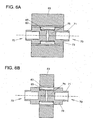
- the projections 83 provided on the portions of the outer circumferential surfaces of the outer shafts 73 which are fittingly inserted into the outer core portion 63 are brought into contact with an inner side of the outer core portion 63 to thereby realize the stable fixing of the shaft portions 70.
- a distance between outer end portions of the left and right outer shafts 73 is a length which is substantially equal to a distance which is slightly shorter than a distance between inner sides of the left and right side plates 37 of the printing unit 21.
- Portions of the bearing shafts 71 which project from the corresponding outer shafts 73 are inserted in the roll guide grooves 25, whereby the roll tape 50 is accommodated within the roll tape accommodating space 23, and a center of the printing unit 21 and a widthwise center of the roll tape 50 are made to coincide with each other with the end portions of the outer shafts 73 of the left and right shaft portions 70 brought into light contact with the corresponding guide ribs 27.
- the width of the outer core portion 63 which is the axial length thereof can be extended to its maximum width in which the outer core portion 63 project from both end portions of the inner core portion 65 in the direction of its axial length by a distance equal to an axial length of the outer shaft 73 of the shaft portion 70.
- the width of the outer core portion 63 which is the axial length thereof can be shortened so as to match the width of the printing tape 53.
- the main body portion 61 adopts the double cylinder construction made up of the inner core portion 65 and the outer core portion 63, and the outer core portion 63 is given the width which matches the width of the printing tape 53 which is the printing tape. Therefore, when winding the printing tape around the tape core 60, it is possible to align the center of the tape core 60 with the center of the printing tape to thereby facilitate the winding of the printing tape around the tape core 60.
- the insertion portions 75 are fittingly inserted into the inner core portion 65 from both the sides thereof so that the shaft portions 70 are respectively provided at both sides of the core main body portion 61, and therefore, with the sizes and the shapes of the inner core portion 65 and the shaft portions 70 made constant, it is possible to load roll tapes 50 made up of printing tapes of different tape widths in a certain type of printer.
- the respective insertion portions 75 of the outer shafts 73 can be fittingly inserted into the inner core portion 65 with the projections 83 on the outer shafts 73 brought into contact with the inner side of the outer core portion 63. Therefore, with a roll tape 50 having a wide tape width in which a load applied when the tape is pulled out is increased, the tape core 60 is made such that the core main body portion 61 and the shaft portions 70 are connected strongly.
- the width of the printing tape 53 is made to match the width of the outer core portion 63, when the printing tape 53 is wound around the tape core 60 to prepare a roll tape 50, the widthwise centers of the printing tape 53 and the tape core 60 can easily be made to coincide with each other, thereby making it possible to prepare the roll tape 50 in which the widthwise centers of the printing tape 53 and the tape core 60 coincide with each other.
- the roll tape 50 which uses the printing tape 53 can be prepared as a printing tape for a printer on which characters or the like can easily be printed by the printing head 14 without using an ink ribbon, thereby making it possible to prepare various types of labels by reducing the waste of natural resources.
- the space is defined between the bearing shaft 71 and the bearing shaft 71 by providing the spokes 67 therebetween.
- the cylindrical hollow portion is also provided in the bearing shaft 71 along the axis thereof.
- the core main body portion 61 of the tape core 60 is made up of the outer core portion 63 and the inner core portion 65, and the inner core portion 65 and the outer core portion 63 are made integral with each other by the spokes 67 so as to provide the space therebetween.
- the shaft portions 70 and the core main body portion 61 are made light in weight, thereby making it possible to realize the conservation of natural resources.
- the configuration of the insertion portion 75 is not limited to the cross shape which is formed by causing the two plate members to intersect each other. According to another embodiment, a configuration can be adopted in which an insertion portion 75 is made up of plate members which are disposed so as to extend radially in a plurality of directions from the center of an end wall 77. Alternatively, according to a further embodiment, a configuration can also be adopted in which an insertion portion 75 is formed into a cylindrical shape which is concentric with a bearing shaft 71 and an outer shaft 73.
Landscapes
- Unwinding Webs (AREA)
- Handling Of Continuous Sheets Of Paper (AREA)
- Electronic Switches (AREA)
- Storage Of Web-Like Or Filamentary Materials (AREA)
- Delivering By Means Of Belts And Rollers (AREA)
Claims (8)
- Rollband, umfassend:einen Kernhauptkörperabschnitt (61), der einen Innenkernabschnitt (65) und einen Außenkernabschnitt (63) umfasst, der sich weiter axial nach außen erstreckt als der Innenkernabschnitt (65) und der einen größeren Durchmesser als ein Durchmesser des Innenkernabschnittes (65) hat;zwei Wellenabschnitte (70), die jeweils umfassen: eine äußere Welle (73), von der wenigstens ein Teil ihres Außenumfangs passend in den Außenkernabschnitt (63) eingefügt ist, einen Einfügeabschnitt (77), der mit der äußeren Welle (73) konzentrisch ist und weiter in eine Richtung hervorragt als die äußere Welle (73), so dass wenigstens ein Teil seines Umfangs passend in den Innenkernabschnitt (65) eingefügt ist, und eine Lagerwelle (71), die mit der äußeren Welle (73) konzentrisch ist und weiter in die andere Richtung hervorragt als die äußere Welle (73); undein Druckband (53), das um einen Außenumfang des Außenkernabschnittes (63) des Kernhauptkörperabschnittes (61) gewickelt ist, der durch Koppeln der beiden Wellenabschnitte (70) mit dem Kernhauptkörperabschnitt (61) von beiden axialen Seiten desselben für eine integrale Verbindung vereinigt ist;dadurch gekennzeichnet, dassder Außenkernabschnitt (63) eine axiale Länge hat, die einer Bandbreite des Druckbandes (53) entspricht, und der Innenkernabschnitt (65) eine axiale Länge hat, die im wesentlichen gleich einer Summe axialer Längen der beiden Einfügeabschnitte (77) unabhängig von der axialen Länge des Außenkernabschnittes (63) ist.
- Rollband nach Anspruch 1, dadurch gekennzeichnet, dass das Druckband (53) ein wärmeempfindliches Papierband ist.
- Rollband nach einem der Ansprüche 1 oder 2, dadurch gekennzeichnet, dass eine axiale Länge des Außenkernabschnittes (63) eine Länge ist, die im wesentlichen gleich einer Bandbreite des Druckbandes (53) ist oder diese überschreitet.
- Rollband nach einem der Ansprüche 1 bis 3, dadurch gekennzeichnet, dass der Innenkernabschnitt (65), der Außenkernabschnitt (63), die äußeren Wellen (73) und die Lagerwellen (71) zylindrisch sind.
- Rollband nach einem der Ansprüche 1 bis 4, dadurch gekennzeichnet, dass der Kernhauptkörperabschnitt (61) derart beschaffen ist, dass der Außenkernabschnitt (63) und der Innenkernabschnitt (65) zueinander konzentrisch sind und der Innenkernabschnitt (65) an einer Innenseite des Außenkernabschnittes (63) durch eine Vielzahl plattenförmiger Speichen (67) befestigt ist.
- Rollband nach einem der Ansprüche 1 bis 5, dadurch gekennzeichnet, dass der Wellenabschnitt (70) derart beschaffen ist, dass die Lagerwelle (71) innerhalb der äußeren Welle (73) durch eine Vielzahl von plattenförmigen Zusatzwänden (81) gehalten ist, so dass ein Ende der äußeren Welle (73) und ein Ende der Lagerwelle (71) zueinander ausgerichtet sind.
- Drucker, umfassend:einen Kernhauptkörperabschnitt (61), der einen Innenkernabschnitt (65) und einen Außenkernabschnitt (63) umfasst, der sich weiter axial nach außen erstreckt als der Innenkernabschnitt (65) und der einen größeren Durchmesser als ein Durchmesser des Innenkernabschnittes (65) hat;zwei Wellenabschnitte (70), die jeweils umfassen: eine äußere Welle (73), von der wenigstens ein Teil ihres Außenumfangs passend in den Außenkernabschnitt (63) eingefügt ist, einen Einfügeabschnitt (77), der mit der äußeren Welle (73) konzentrisch ist und weiter in eine Richtung hervorragt als die äußere Welle (73), so dass wenigstens ein Teil seines Umfangs passend in den Innenkernabschnitt (65) eingefügt ist, und eine Lagerwelle (71), die mit der äußeren Welle (73) konzentrisch ist und weiter in die andere Richtung hervorragt als die äußere Welle (73);ein Rollband, das aus einem Druckband (53) besteht, das um einen Außenumfang des Außenkernabschnittes (63) des Kernhauptkörperabschnittes (61) gewickelt ist, der durch Koppeln der beiden Wellenabschnitte (70) mit dem Kernhauptkörperabschnitt (61) von beiden axialen Seiten desselben für eine integrale Verbindung vereinigt ist;zwei Führungsrillen (25), die die Wellenabschnitte (70) drehbar lagern; undeinen Druckabschnitt, der das Druckband (53) trägt, während er ein unaufgewickeltes freies Ende des Druckbandes (53) durch einen Druckkopf (14) und eine Platte (31) hält, die derart angeordnet ist, dass sie dem Druckkopf (14) zugewandt ist, und der Daten auf das Druckband (53) druckt;dadurch gekennzeichnet, dassder Außenkernabschnitt (63) eine axiale Länge hat, die einer Bandbreite des Druckbandes (53) entspricht, und der Innenkernabschnitt (65) eine axiale Länge hat, die im wesentlichen gleich einer Summe axialer Längen der beiden Einfügeabschnitte (77) unabhängig von der axialen Länge des Außenkernabschnittes (63) ist.
- Drucker nach Anspruch 7, dadurch gekennzeichnet, dass der Druckkopf (14) ein Thermokopf ist.
Applications Claiming Priority (1)
| Application Number | Priority Date | Filing Date | Title |
|---|---|---|---|
| JP2012033833A JP5565639B2 (ja) | 2012-02-20 | 2012-02-20 | ロールテープ及び印字装置 |
Publications (2)
| Publication Number | Publication Date |
|---|---|
| EP2628601A1 EP2628601A1 (de) | 2013-08-21 |
| EP2628601B1 true EP2628601B1 (de) | 2015-04-01 |
Family
ID=47722168
Family Applications (1)
| Application Number | Title | Priority Date | Filing Date |
|---|---|---|---|
| EP13155944.5A Active EP2628601B1 (de) | 2012-02-20 | 2013-02-20 | Rollband und Drucker |
Country Status (4)
| Country | Link |
|---|---|
| US (1) | US8920054B2 (de) |
| EP (1) | EP2628601B1 (de) |
| JP (1) | JP5565639B2 (de) |
| CN (1) | CN103253011B (de) |
Families Citing this family (10)
| Publication number | Priority date | Publication date | Assignee | Title |
|---|---|---|---|---|
| JP6232932B2 (ja) * | 2013-10-31 | 2017-11-22 | ブラザー工業株式会社 | 軸付きロール機構、テープカートリッジ |
| USD859517S1 (en) * | 2017-08-17 | 2019-09-10 | Daniel B. Meyer | Side-opening printer with front interface screen |
| USD875830S1 (en) * | 2017-10-05 | 2020-02-18 | Intertape Polymer Corp. | Tape dispenser |
| USD890990S1 (en) | 2018-03-08 | 2020-07-21 | Coty Inc. | Machine for customizing hair dye formulations |
| USD894264S1 (en) * | 2018-03-08 | 2020-08-25 | Coty Inc. | Label printer for system for customizing hair dye formulations |
| CN108638673B (zh) * | 2018-05-07 | 2020-01-14 | 深圳怡化电脑股份有限公司 | 一种打印机用转轴、打印机及金融自助终端 |
| JP2020104331A (ja) * | 2018-12-26 | 2020-07-09 | セイコーエプソン株式会社 | テープ供給装置およびテープ印刷システム |
| JP7347013B2 (ja) * | 2019-08-29 | 2023-09-20 | セイコーエプソン株式会社 | 印刷装置 |
| US12227002B2 (en) | 2022-08-24 | 2025-02-18 | Zebra Technologies Corporation | Electronic tag mounts for printer media supply rolls |
| USD1096937S1 (en) * | 2024-05-20 | 2025-10-07 | Shenzhen Xiaoguan Technology Co., Ltd. | Sticker dispenser |
Family Cites Families (24)
| Publication number | Priority date | Publication date | Assignee | Title |
|---|---|---|---|---|
| US1962959A (en) * | 1933-01-09 | 1934-06-12 | Du Pont Film Mfg Corp | Spooled film |
| CH466713A (de) * | 1966-12-14 | 1968-12-15 | Ciba Geigy | Wickelkassette für Photopapierrollen an automatischen Kopiermaschinen |
| JPH0522531Y2 (de) * | 1988-05-09 | 1993-06-10 | ||
| JPH02163247A (ja) | 1988-12-14 | 1990-06-22 | Mitsubishi Electric Corp | ファクシミリ装置 |
| JPH0717671A (ja) * | 1993-07-02 | 1995-01-20 | Fujikura Ltd | 線条体の巻取ドラム |
| US6190069B1 (en) * | 1994-05-25 | 2001-02-20 | Brother Kogyo Kabushiki Kaisha | Tape-shaped label printing device |
| JPH08157146A (ja) * | 1994-12-05 | 1996-06-18 | Daishinku Co | 電子部品用テーピングリール |
| US6196495B1 (en) | 1996-05-30 | 2001-03-06 | Kolon Industries, Inc. | Reel for winding photosensitive film |
| JPH10291707A (ja) | 1997-04-15 | 1998-11-04 | Brother Ind Ltd | ウエッブロール及びウエッブロール収納カセット |
| JPH1142821A (ja) | 1997-07-29 | 1999-02-16 | Tec Corp | プリンタ |
| JP4401534B2 (ja) * | 1999-08-26 | 2010-01-20 | 東北リコー株式会社 | マスタ原紙ロール及びマスタ原紙ロール保持装置 |
| JP2002096515A (ja) * | 2000-09-21 | 2002-04-02 | Brother Ind Ltd | ロールカセット及びテープ印刷装置 |
| JP4452392B2 (ja) * | 2000-09-29 | 2010-04-21 | セイコーエプソン株式会社 | テープ印刷装置 |
| JP3827204B2 (ja) * | 2000-12-19 | 2006-09-27 | 富士写真フイルム株式会社 | 感光材料用マガジン |
| EP1249729A3 (de) * | 2001-04-12 | 2005-07-13 | Fuji Photo Film Co., Ltd. | Gewickelter Artikel und Verfahren und Vorrichtung zu dessen Verarbeitung |
| JP2002341488A (ja) * | 2001-05-15 | 2002-11-27 | Fuji Photo Film Co Ltd | アダプタ付き遮光性感光材料ロール |
| JP4125887B2 (ja) | 2001-11-26 | 2008-07-30 | 日東電工株式会社 | アクリル系粘着シート |
| JP3789821B2 (ja) * | 2002-01-10 | 2006-06-28 | 大日本印刷株式会社 | 供給用ボビン |
| JP2003211763A (ja) * | 2002-01-28 | 2003-07-29 | Fuji Photo Film Co Ltd | プリンタ |
| JP2003341165A (ja) * | 2002-05-28 | 2003-12-03 | Fuji Photo Film Co Ltd | プリンタ |
| US7036765B2 (en) * | 2003-04-04 | 2006-05-02 | Chandaria Ashok V | Polarized tape dispenser |
| US7387458B2 (en) * | 2003-08-13 | 2008-06-17 | Paxar Americas, Inc. | Printer and method of printing with a plurality of selectable registration sensors |
| US7125182B2 (en) * | 2004-02-17 | 2006-10-24 | Paxar Americas, Inc. | Printer |
| JP2010120211A (ja) * | 2008-11-18 | 2010-06-03 | Seiko Epson Corp | 印刷装置及びカートリッジ |
-
2012
- 2012-02-20 JP JP2012033833A patent/JP5565639B2/ja active Active
-
2013
- 2013-02-19 US US13/770,843 patent/US8920054B2/en active Active
- 2013-02-20 CN CN201310054298.XA patent/CN103253011B/zh active Active
- 2013-02-20 EP EP13155944.5A patent/EP2628601B1/de active Active
Also Published As
| Publication number | Publication date |
|---|---|
| CN103253011A (zh) | 2013-08-21 |
| JP2013170026A (ja) | 2013-09-02 |
| EP2628601A1 (de) | 2013-08-21 |
| US20130216292A1 (en) | 2013-08-22 |
| JP5565639B2 (ja) | 2014-08-06 |
| US8920054B2 (en) | 2014-12-30 |
| CN103253011B (zh) | 2016-08-10 |
Similar Documents
| Publication | Publication Date | Title |
|---|---|---|
| US8920054B2 (en) | Roll tape and printer | |
| US8974131B2 (en) | Tape catridge and tape printer | |
| JP4492125B2 (ja) | ロールシートホルダ及びテープ印刷装置 | |
| US10889137B2 (en) | Tape cartridge | |
| EP1859950A2 (de) | Bandkassette und Drucker | |
| JP2013220876A (ja) | ロールホルダ | |
| EP4382302A1 (de) | Druckvorrichtung | |
| CN111902292A (zh) | 印刷盒、带引导件以及印刷装置 | |
| CN111918775B (zh) | 色带盒 | |
| TW526146B (en) | Color tape cassette | |
| EP4205988B1 (de) | Zusatzbandkassette | |
| WO2011030579A1 (ja) | テープカセット | |
| JP2017064935A (ja) | リボンカセット | |
| JPH02235673A (ja) | インクリボンの取付方法およびその装置 | |
| CN105377564A (zh) | 打印机 | |
| CN210763345U (zh) | 一种纸盒组件和打印机 | |
| JP2006315791A (ja) | ロール紙ホルダ | |
| JP2016068482A (ja) | ボビンとプリンタの組合体 | |
| JP2022052130A (ja) | 印刷装置及び媒体アダプタ | |
| JPH02208080A (ja) | インクリボン装着装置 | |
| JP2000043335A (ja) | テープカセット | |
| JP3643280B2 (ja) | インクリボンカセット | |
| JP3109602U (ja) | 支持筒体及び交換用インクリボン | |
| JP2007313673A (ja) | プリンタ | |
| KR20240174554A (ko) | 다수 규격 리본롤 사용과 열전사 리본 세이빙 데스크탑 프린터 시스템 |
Legal Events
| Date | Code | Title | Description |
|---|---|---|---|
| PUAI | Public reference made under article 153(3) epc to a published international application that has entered the european phase |
Free format text: ORIGINAL CODE: 0009012 |
|
| 17P | Request for examination filed |
Effective date: 20130220 |
|
| AK | Designated contracting states |
Kind code of ref document: A1 Designated state(s): AL AT BE BG CH CY CZ DE DK EE ES FI FR GB GR HR HU IE IS IT LI LT LU LV MC MK MT NL NO PL PT RO RS SE SI SK SM TR |
|
| AX | Request for extension of the european patent |
Extension state: BA ME |
|
| GRAP | Despatch of communication of intention to grant a patent |
Free format text: ORIGINAL CODE: EPIDOSNIGR1 |
|
| RIC1 | Information provided on ipc code assigned before grant |
Ipc: B41J 11/00 20060101ALI20140829BHEP Ipc: B41J 3/407 20060101ALI20140829BHEP Ipc: B41J 15/04 20060101AFI20140829BHEP |
|
| INTG | Intention to grant announced |
Effective date: 20140917 |
|
| GRAS | Grant fee paid |
Free format text: ORIGINAL CODE: EPIDOSNIGR3 |
|
| GRAA | (expected) grant |
Free format text: ORIGINAL CODE: 0009210 |
|
| AK | Designated contracting states |
Kind code of ref document: B1 Designated state(s): AL AT BE BG CH CY CZ DE DK EE ES FI FR GB GR HR HU IE IS IT LI LT LU LV MC MK MT NL NO PL PT RO RS SE SI SK SM TR |
|
| REG | Reference to a national code |
Ref country code: GB Ref legal event code: FG4D |
|
| REG | Reference to a national code |
Ref country code: CH Ref legal event code: EP |
|
| REG | Reference to a national code |
Ref country code: IE Ref legal event code: FG4D |
|
| REG | Reference to a national code |
Ref country code: DE Ref legal event code: R096 Ref document number: 602013001336 Country of ref document: DE Effective date: 20150513 |
|
| REG | Reference to a national code |
Ref country code: AT Ref legal event code: REF Ref document number: 718829 Country of ref document: AT Kind code of ref document: T Effective date: 20150515 |
|
| REG | Reference to a national code |
Ref country code: NL Ref legal event code: VDEP Effective date: 20150401 |
|
| REG | Reference to a national code |
Ref country code: AT Ref legal event code: MK05 Ref document number: 718829 Country of ref document: AT Kind code of ref document: T Effective date: 20150401 |
|
| REG | Reference to a national code |
Ref country code: LT Ref legal event code: MG4D |
|
| PG25 | Lapsed in a contracting state [announced via postgrant information from national office to epo] |
Ref country code: NL Free format text: LAPSE BECAUSE OF FAILURE TO SUBMIT A TRANSLATION OF THE DESCRIPTION OR TO PAY THE FEE WITHIN THE PRESCRIBED TIME-LIMIT Effective date: 20150401 |
|
| PG25 | Lapsed in a contracting state [announced via postgrant information from national office to epo] |
Ref country code: HR Free format text: LAPSE BECAUSE OF FAILURE TO SUBMIT A TRANSLATION OF THE DESCRIPTION OR TO PAY THE FEE WITHIN THE PRESCRIBED TIME-LIMIT Effective date: 20150401 Ref country code: PT Free format text: LAPSE BECAUSE OF FAILURE TO SUBMIT A TRANSLATION OF THE DESCRIPTION OR TO PAY THE FEE WITHIN THE PRESCRIBED TIME-LIMIT Effective date: 20150803 Ref country code: ES Free format text: LAPSE BECAUSE OF FAILURE TO SUBMIT A TRANSLATION OF THE DESCRIPTION OR TO PAY THE FEE WITHIN THE PRESCRIBED TIME-LIMIT Effective date: 20150401 Ref country code: NO Free format text: LAPSE BECAUSE OF FAILURE TO SUBMIT A TRANSLATION OF THE DESCRIPTION OR TO PAY THE FEE WITHIN THE PRESCRIBED TIME-LIMIT Effective date: 20150701 Ref country code: FI Free format text: LAPSE BECAUSE OF FAILURE TO SUBMIT A TRANSLATION OF THE DESCRIPTION OR TO PAY THE FEE WITHIN THE PRESCRIBED TIME-LIMIT Effective date: 20150401 Ref country code: CZ Free format text: LAPSE BECAUSE OF FAILURE TO SUBMIT A TRANSLATION OF THE DESCRIPTION OR TO PAY THE FEE WITHIN THE PRESCRIBED TIME-LIMIT Effective date: 20150401 Ref country code: LT Free format text: LAPSE BECAUSE OF FAILURE TO SUBMIT A TRANSLATION OF THE DESCRIPTION OR TO PAY THE FEE WITHIN THE PRESCRIBED TIME-LIMIT Effective date: 20150401 |
|
| PG25 | Lapsed in a contracting state [announced via postgrant information from national office to epo] |
Ref country code: GR Free format text: LAPSE BECAUSE OF FAILURE TO SUBMIT A TRANSLATION OF THE DESCRIPTION OR TO PAY THE FEE WITHIN THE PRESCRIBED TIME-LIMIT Effective date: 20150702 Ref country code: AT Free format text: LAPSE BECAUSE OF FAILURE TO SUBMIT A TRANSLATION OF THE DESCRIPTION OR TO PAY THE FEE WITHIN THE PRESCRIBED TIME-LIMIT Effective date: 20150401 Ref country code: RS Free format text: LAPSE BECAUSE OF FAILURE TO SUBMIT A TRANSLATION OF THE DESCRIPTION OR TO PAY THE FEE WITHIN THE PRESCRIBED TIME-LIMIT Effective date: 20150401 Ref country code: LV Free format text: LAPSE BECAUSE OF FAILURE TO SUBMIT A TRANSLATION OF THE DESCRIPTION OR TO PAY THE FEE WITHIN THE PRESCRIBED TIME-LIMIT Effective date: 20150401 Ref country code: IS Free format text: LAPSE BECAUSE OF FAILURE TO SUBMIT A TRANSLATION OF THE DESCRIPTION OR TO PAY THE FEE WITHIN THE PRESCRIBED TIME-LIMIT Effective date: 20150801 |
|
| REG | Reference to a national code |
Ref country code: DE Ref legal event code: R097 Ref document number: 602013001336 Country of ref document: DE |
|
| REG | Reference to a national code |
Ref country code: FR Ref legal event code: PLFP Year of fee payment: 4 |
|
| PG25 | Lapsed in a contracting state [announced via postgrant information from national office to epo] |
Ref country code: DK Free format text: LAPSE BECAUSE OF FAILURE TO SUBMIT A TRANSLATION OF THE DESCRIPTION OR TO PAY THE FEE WITHIN THE PRESCRIBED TIME-LIMIT Effective date: 20150401 Ref country code: EE Free format text: LAPSE BECAUSE OF FAILURE TO SUBMIT A TRANSLATION OF THE DESCRIPTION OR TO PAY THE FEE WITHIN THE PRESCRIBED TIME-LIMIT Effective date: 20150401 |
|
| PLBE | No opposition filed within time limit |
Free format text: ORIGINAL CODE: 0009261 |
|
| STAA | Information on the status of an ep patent application or granted ep patent |
Free format text: STATUS: NO OPPOSITION FILED WITHIN TIME LIMIT |
|
| PG25 | Lapsed in a contracting state [announced via postgrant information from national office to epo] |
Ref country code: RO Free format text: LAPSE BECAUSE OF NON-PAYMENT OF DUE FEES Effective date: 20150401 Ref country code: SK Free format text: LAPSE BECAUSE OF FAILURE TO SUBMIT A TRANSLATION OF THE DESCRIPTION OR TO PAY THE FEE WITHIN THE PRESCRIBED TIME-LIMIT Effective date: 20150401 Ref country code: PL Free format text: LAPSE BECAUSE OF FAILURE TO SUBMIT A TRANSLATION OF THE DESCRIPTION OR TO PAY THE FEE WITHIN THE PRESCRIBED TIME-LIMIT Effective date: 20150401 |
|
| 26N | No opposition filed |
Effective date: 20160105 |
|
| PG25 | Lapsed in a contracting state [announced via postgrant information from national office to epo] |
Ref country code: IT Free format text: LAPSE BECAUSE OF FAILURE TO SUBMIT A TRANSLATION OF THE DESCRIPTION OR TO PAY THE FEE WITHIN THE PRESCRIBED TIME-LIMIT Effective date: 20150401 |
|
| PG25 | Lapsed in a contracting state [announced via postgrant information from national office to epo] |
Ref country code: BE Free format text: LAPSE BECAUSE OF NON-PAYMENT OF DUE FEES Effective date: 20160229 Ref country code: SI Free format text: LAPSE BECAUSE OF FAILURE TO SUBMIT A TRANSLATION OF THE DESCRIPTION OR TO PAY THE FEE WITHIN THE PRESCRIBED TIME-LIMIT Effective date: 20150401 |
|
| PG25 | Lapsed in a contracting state [announced via postgrant information from national office to epo] |
Ref country code: BE Free format text: LAPSE BECAUSE OF FAILURE TO SUBMIT A TRANSLATION OF THE DESCRIPTION OR TO PAY THE FEE WITHIN THE PRESCRIBED TIME-LIMIT Effective date: 20150401 |
|
| PG25 | Lapsed in a contracting state [announced via postgrant information from national office to epo] |
Ref country code: MC Free format text: LAPSE BECAUSE OF FAILURE TO SUBMIT A TRANSLATION OF THE DESCRIPTION OR TO PAY THE FEE WITHIN THE PRESCRIBED TIME-LIMIT Effective date: 20150401 Ref country code: LU Free format text: LAPSE BECAUSE OF FAILURE TO SUBMIT A TRANSLATION OF THE DESCRIPTION OR TO PAY THE FEE WITHIN THE PRESCRIBED TIME-LIMIT Effective date: 20160220 |
|
| REG | Reference to a national code |
Ref country code: CH Ref legal event code: PL |
|
| PG25 | Lapsed in a contracting state [announced via postgrant information from national office to epo] |
Ref country code: CH Free format text: LAPSE BECAUSE OF NON-PAYMENT OF DUE FEES Effective date: 20160229 Ref country code: LI Free format text: LAPSE BECAUSE OF NON-PAYMENT OF DUE FEES Effective date: 20160229 |
|
| REG | Reference to a national code |
Ref country code: IE Ref legal event code: MM4A |
|
| REG | Reference to a national code |
Ref country code: FR Ref legal event code: PLFP Year of fee payment: 5 |
|
| PG25 | Lapsed in a contracting state [announced via postgrant information from national office to epo] |
Ref country code: IE Free format text: LAPSE BECAUSE OF NON-PAYMENT OF DUE FEES Effective date: 20160220 |
|
| PG25 | Lapsed in a contracting state [announced via postgrant information from national office to epo] |
Ref country code: SE Free format text: LAPSE BECAUSE OF FAILURE TO SUBMIT A TRANSLATION OF THE DESCRIPTION OR TO PAY THE FEE WITHIN THE PRESCRIBED TIME-LIMIT Effective date: 20150401 |
|
| PG25 | Lapsed in a contracting state [announced via postgrant information from national office to epo] |
Ref country code: MT Free format text: LAPSE BECAUSE OF FAILURE TO SUBMIT A TRANSLATION OF THE DESCRIPTION OR TO PAY THE FEE WITHIN THE PRESCRIBED TIME-LIMIT Effective date: 20150401 |
|
| REG | Reference to a national code |
Ref country code: FR Ref legal event code: PLFP Year of fee payment: 6 |
|
| PG25 | Lapsed in a contracting state [announced via postgrant information from national office to epo] |
Ref country code: SM Free format text: LAPSE BECAUSE OF FAILURE TO SUBMIT A TRANSLATION OF THE DESCRIPTION OR TO PAY THE FEE WITHIN THE PRESCRIBED TIME-LIMIT Effective date: 20150401 Ref country code: HU Free format text: LAPSE BECAUSE OF FAILURE TO SUBMIT A TRANSLATION OF THE DESCRIPTION OR TO PAY THE FEE WITHIN THE PRESCRIBED TIME-LIMIT; INVALID AB INITIO Effective date: 20130220 Ref country code: CY Free format text: LAPSE BECAUSE OF FAILURE TO SUBMIT A TRANSLATION OF THE DESCRIPTION OR TO PAY THE FEE WITHIN THE PRESCRIBED TIME-LIMIT Effective date: 20150401 |
|
| PG25 | Lapsed in a contracting state [announced via postgrant information from national office to epo] |
Ref country code: MK Free format text: LAPSE BECAUSE OF FAILURE TO SUBMIT A TRANSLATION OF THE DESCRIPTION OR TO PAY THE FEE WITHIN THE PRESCRIBED TIME-LIMIT Effective date: 20150401 Ref country code: TR Free format text: LAPSE BECAUSE OF FAILURE TO SUBMIT A TRANSLATION OF THE DESCRIPTION OR TO PAY THE FEE WITHIN THE PRESCRIBED TIME-LIMIT Effective date: 20150401 Ref country code: MT Free format text: LAPSE BECAUSE OF FAILURE TO SUBMIT A TRANSLATION OF THE DESCRIPTION OR TO PAY THE FEE WITHIN THE PRESCRIBED TIME-LIMIT Effective date: 20160229 |
|
| PG25 | Lapsed in a contracting state [announced via postgrant information from national office to epo] |
Ref country code: BG Free format text: LAPSE BECAUSE OF FAILURE TO SUBMIT A TRANSLATION OF THE DESCRIPTION OR TO PAY THE FEE WITHIN THE PRESCRIBED TIME-LIMIT Effective date: 20150401 |
|
| PG25 | Lapsed in a contracting state [announced via postgrant information from national office to epo] |
Ref country code: AL Free format text: LAPSE BECAUSE OF FAILURE TO SUBMIT A TRANSLATION OF THE DESCRIPTION OR TO PAY THE FEE WITHIN THE PRESCRIBED TIME-LIMIT Effective date: 20150401 |
|
| PGFP | Annual fee paid to national office [announced via postgrant information from national office to epo] |
Ref country code: FR Payment date: 20251231 Year of fee payment: 14 |
|
| PGFP | Annual fee paid to national office [announced via postgrant information from national office to epo] |
Ref country code: GB Payment date: 20260106 Year of fee payment: 14 |
|
| PGFP | Annual fee paid to national office [announced via postgrant information from national office to epo] |
Ref country code: DE Payment date: 20251230 Year of fee payment: 14 |