EP2628570B1 - Porte-outil à changement rapide avec aimant annulaire - Google Patents
Porte-outil à changement rapide avec aimant annulaire Download PDFInfo
- Publication number
- EP2628570B1 EP2628570B1 EP13155401.6A EP13155401A EP2628570B1 EP 2628570 B1 EP2628570 B1 EP 2628570B1 EP 13155401 A EP13155401 A EP 13155401A EP 2628570 B1 EP2628570 B1 EP 2628570B1
- Authority
- EP
- European Patent Office
- Prior art keywords
- bit
- sleeve
- collar
- tool
- tool bit
- Prior art date
- Legal status (The legal status is an assumption and is not a legal conclusion. Google has not performed a legal analysis and makes no representation as to the accuracy of the status listed.)
- Active
Links
- 238000004891 communication Methods 0.000 claims description 2
- 238000007667 floating Methods 0.000 description 116
- 230000002829 reductive effect Effects 0.000 description 20
- 239000004033 plastic Substances 0.000 description 12
- 239000005060 rubber Substances 0.000 description 11
- 238000000034 method Methods 0.000 description 8
- 230000000717 retained effect Effects 0.000 description 7
- 239000000463 material Substances 0.000 description 5
- 230000002441 reversible effect Effects 0.000 description 5
- 229910000831 Steel Inorganic materials 0.000 description 3
- 239000000853 adhesive Substances 0.000 description 3
- 230000001070 adhesive effect Effects 0.000 description 3
- 238000003780 insertion Methods 0.000 description 3
- 230000037431 insertion Effects 0.000 description 3
- 238000009434 installation Methods 0.000 description 3
- 239000002184 metal Substances 0.000 description 3
- 230000036961 partial effect Effects 0.000 description 3
- 239000010959 steel Substances 0.000 description 3
- 230000007935 neutral effect Effects 0.000 description 2
- 229910000639 Spring steel Inorganic materials 0.000 description 1
- 244000309464 bull Species 0.000 description 1
- 230000008878 coupling Effects 0.000 description 1
- 238000010168 coupling process Methods 0.000 description 1
- 238000005859 coupling reaction Methods 0.000 description 1
- 238000005516 engineering process Methods 0.000 description 1
- 230000001747 exhibiting effect Effects 0.000 description 1
- 230000000670 limiting effect Effects 0.000 description 1
- 239000000696 magnetic material Substances 0.000 description 1
- 230000014759 maintenance of location Effects 0.000 description 1
- 230000013011 mating Effects 0.000 description 1
- 238000000465 moulding Methods 0.000 description 1
- 230000000087 stabilizing effect Effects 0.000 description 1
Images


Classifications
-
- B—PERFORMING OPERATIONS; TRANSPORTING
- B25—HAND TOOLS; PORTABLE POWER-DRIVEN TOOLS; MANIPULATORS
- B25B—TOOLS OR BENCH DEVICES NOT OTHERWISE PROVIDED FOR, FOR FASTENING, CONNECTING, DISENGAGING OR HOLDING
- B25B23/00—Details of, or accessories for, spanners, wrenches, screwdrivers
- B25B23/0007—Connections or joints between tool parts
- B25B23/0035—Connection means between socket or screwdriver bit and tool
-
- B—PERFORMING OPERATIONS; TRANSPORTING
- B23—MACHINE TOOLS; METAL-WORKING NOT OTHERWISE PROVIDED FOR
- B23B—TURNING; BORING
- B23B31/00—Chucks; Expansion mandrels; Adaptations thereof for remote control
- B23B31/02—Chucks
- B23B31/10—Chucks characterised by the retaining or gripping devices or their immediate operating means
- B23B31/107—Retention by laterally-acting detents, e.g. pins, screws, wedges; Retention by loose elements, e.g. balls
- B23B31/1071—Retention by balls
-
- B—PERFORMING OPERATIONS; TRANSPORTING
- B23—MACHINE TOOLS; METAL-WORKING NOT OTHERWISE PROVIDED FOR
- B23B—TURNING; BORING
- B23B31/00—Chucks; Expansion mandrels; Adaptations thereof for remote control
- B23B31/02—Chucks
- B23B31/10—Chucks characterised by the retaining or gripping devices or their immediate operating means
- B23B31/12—Chucks with simultaneously-acting jaws, whether or not also individually adjustable
- B23B31/22—Jaws in the form of balls
-
- B—PERFORMING OPERATIONS; TRANSPORTING
- B25—HAND TOOLS; PORTABLE POWER-DRIVEN TOOLS; MANIPULATORS
- B25B—TOOLS OR BENCH DEVICES NOT OTHERWISE PROVIDED FOR, FOR FASTENING, CONNECTING, DISENGAGING OR HOLDING
- B25B23/00—Details of, or accessories for, spanners, wrenches, screwdrivers
- B25B23/02—Arrangements for handling screws or nuts
- B25B23/08—Arrangements for handling screws or nuts for holding or positioning screw or nut prior to or during its rotation
- B25B23/12—Arrangements for handling screws or nuts for holding or positioning screw or nut prior to or during its rotation using magnetic means
-
- Y—GENERAL TAGGING OF NEW TECHNOLOGICAL DEVELOPMENTS; GENERAL TAGGING OF CROSS-SECTIONAL TECHNOLOGIES SPANNING OVER SEVERAL SECTIONS OF THE IPC; TECHNICAL SUBJECTS COVERED BY FORMER USPC CROSS-REFERENCE ART COLLECTIONS [XRACs] AND DIGESTS
- Y10—TECHNICAL SUBJECTS COVERED BY FORMER USPC
- Y10T—TECHNICAL SUBJECTS COVERED BY FORMER US CLASSIFICATION
- Y10T279/00—Chucks or sockets
- Y10T279/17—Socket type
- Y10T279/17411—Spring biased jaws
-
- Y—GENERAL TAGGING OF NEW TECHNOLOGICAL DEVELOPMENTS; GENERAL TAGGING OF CROSS-SECTIONAL TECHNOLOGIES SPANNING OVER SEVERAL SECTIONS OF THE IPC; TECHNICAL SUBJECTS COVERED BY FORMER USPC CROSS-REFERENCE ART COLLECTIONS [XRACs] AND DIGESTS
- Y10—TECHNICAL SUBJECTS COVERED BY FORMER USPC
- Y10T—TECHNICAL SUBJECTS COVERED BY FORMER US CLASSIFICATION
- Y10T279/00—Chucks or sockets
- Y10T279/17—Socket type
- Y10T279/17666—Radially reciprocating jaws
- Y10T279/17692—Moving-cam actuator
- Y10T279/17743—Reciprocating cam sleeve
- Y10T279/17752—Ball or roller jaws
-
- Y—GENERAL TAGGING OF NEW TECHNOLOGICAL DEVELOPMENTS; GENERAL TAGGING OF CROSS-SECTIONAL TECHNOLOGIES SPANNING OVER SEVERAL SECTIONS OF THE IPC; TECHNICAL SUBJECTS COVERED BY FORMER USPC CROSS-REFERENCE ART COLLECTIONS [XRACs] AND DIGESTS
- Y10—TECHNICAL SUBJECTS COVERED BY FORMER USPC
- Y10T—TECHNICAL SUBJECTS COVERED BY FORMER US CLASSIFICATION
- Y10T279/00—Chucks or sockets
- Y10T279/17—Socket type
- Y10T279/17761—Side detent
- Y10T279/17786—Spring
- Y10T279/17794—Sleeved
-
- Y—GENERAL TAGGING OF NEW TECHNOLOGICAL DEVELOPMENTS; GENERAL TAGGING OF CROSS-SECTIONAL TECHNOLOGIES SPANNING OVER SEVERAL SECTIONS OF THE IPC; TECHNICAL SUBJECTS COVERED BY FORMER USPC CROSS-REFERENCE ART COLLECTIONS [XRACs] AND DIGESTS
- Y10—TECHNICAL SUBJECTS COVERED BY FORMER USPC
- Y10T—TECHNICAL SUBJECTS COVERED BY FORMER US CLASSIFICATION
- Y10T279/00—Chucks or sockets
- Y10T279/17—Socket type
- Y10T279/17761—Side detent
- Y10T279/17811—Reciprocating sleeve
-
- Y—GENERAL TAGGING OF NEW TECHNOLOGICAL DEVELOPMENTS; GENERAL TAGGING OF CROSS-SECTIONAL TECHNOLOGIES SPANNING OVER SEVERAL SECTIONS OF THE IPC; TECHNICAL SUBJECTS COVERED BY FORMER USPC CROSS-REFERENCE ART COLLECTIONS [XRACs] AND DIGESTS
- Y10—TECHNICAL SUBJECTS COVERED BY FORMER USPC
- Y10T—TECHNICAL SUBJECTS COVERED BY FORMER US CLASSIFICATION
- Y10T279/00—Chucks or sockets
- Y10T279/32—Means to prevent jaw loosening
Definitions
- the present disclosure relates to power tool and hand tool bits and bit holders and more particularly, to a bit and a quick change bit holder with a floating ring magnet for retaining a fastener to the bit.
- US 2010/133762 discloses a universal tool shank into which a tool bit can be removably received.
- US 2011/167966 discloses a tool coupling structure in which a tool such as a screwdriver bit can be fitted.
- US 2009/107304 discloses a tool retaining device for receiving a tool member.
- US 7086813 discloses a bit chuck assembly in which a tool can be removably held.
- EP 1878524 discloses a driving tool assembly adapted to receive a tool bit.
- EP 1637285 discloses a bit holder device.
- US 7284936 discloses a tool bit and collet assembly.
- US 2010/011918 discloses a screwdriver bit.
- US 2003/145693 discloses a tool retaining device with a barrel.
- DE 10148943 discloses a device for screwdriver bits.
- auxiliary chucks for power and hand tools have become increasingly common, especially as the need and desirability of wider versatility in the use of power tools and hand tools has increased.
- Such auxiliary chucks allow the hand or power tool to be used with any of a number of interchangeable bits. This, in turn, has resulted in demands for greater speed, convenience and ease of insertion and removal of tool bits from such chucks.
- one or more detent balls are positioned within a hollow, barrel-shaped tool bit holder body and are resiliently biased into engagement with a circumferentially-extending groove or recess on the shank of the tool bit.
- An example of such a ball-type mechanism is disclosed in commonly assigned U.S. Patent No. 5,988,957 .
- a spring biased clip is used to, engage the bit within the tool bit holder body. Examples of the spring biased clip design are disclosed in commonly assigned U.S. Patent No. 7,086,813 and 6,929,266 .
- the present disclosure provides a simple, relatively inexpensive quick-acting chuck assembly or bit holder that includes a ring magnet at a forward end of the retraction collar to magnetize a fastener and assist in both retaining the fastener to the bit and stabilizing the fastener during its installation.
- the ring magnet can be supported to allow the magnet to float in a forward direction to engage the fastener or a rearward direction to release the bit for a rapid one handed bit change.
- the length of the float and the geometry of the magnet are such as to allow for the feature to work with fasteners of different head configurations and with all bit lengths within the normally accepted industry tolerances.
- the present disclosure provides a body having a coaxially extending hex-shaped bore therein for receiving a hex-shaped bit.
- a spring biased retraction collar is mounted to the body and engages means for releasably retaining the hex-shaped tool within the bore.
- the retraction collar supports a magnet at a forward end thereof and allows the magnet to float in a forward direction to engage and magnetize a fastener engaging the bit.
- the magnet can be in the form of a ring magnet and can be fixedly mounted to the retraction collar, wherein the magnet causes the retraction collar to move in the forward direction.
- the retraction collar can include a floating sleeve that supports the magnet and allows the magnet to float forward relative to a remainder of the retraction collar.
- a bit holder is provided with a floating ring magnet supported on the bit holder.
- the bit holder can be a pivoting bit holder or a multi-tool bit holder such as a six-in-one rotary tool.
- a tool bit is provided with a floating sleeve that supports a ring magnet at a forward end of the tool bit.
- the floating sleeve can be supported on the tool bit by various techniques as will be disclosed herein.
- the tool bit can be a torsion bit that includes a shank portion and a working region with a reduced diameter torsion zone disposed therebetween.
- the reduced diameter torsion zone has a shoulder on a forward and rearward end of the torsion zone to aid in retaining the floating sleeve on the tool bit.
- a magnet assembly for retaining a fastener on a tool bit, the magnet assembly including a floating sleeve and a first ring magnet disposed at a front end portion of the floating sleeve.
- a second ring magnet is disposed at a rear end portion of the floating sleeve, wherein the first and second ring magnets are arranged with their poles opposing one another such that the floating sleeve is moveable freely along a length of the tool bit, and the first ring magnet is configured to engage a head of a fastener.
- the first and second ring magnets are disposed approximately 10mm apart from each other and can include an O-ring disposed inside of the sleeve between the first and second ring magnets to resist movement of the floating sleeve along the tool bit.
- a bit holder assembly for a rotary tool including a body having a shank at its rearward end and a coaxial socket formed at a second end to allow a tool bit to be inserted therein, the body having an opening formed in the body in communication with said socket.
- a retraction collar is slidably disposed on the body, and is biased forwardly by a coil spring.
- a retainer is held in a bottom of the opening formed in the body by the retraction collar or the coil spring, and said tool bit can be removed by sliding the retraction collar rearwardly, to compress the coil spring and allow the retainer to retract back up the opening.
- a ring magnet is disposed at a forward end of the retraction collar to magnetize a fastener to retain the fastener to the tool bit.
- the ring magnet may be attached directly to the retraction collar or attached to a forward collar received on the retraction collar. If a forward collar is present, it may be slidably and/or removably received on the retraction collar.
- the opening in the body of the bit holder may be an angular slot formed in the body and said coil spring may bias said retainer toward a bottom of the angular slot.
- Example embodiments are provided so that this disclosure will be thorough, and will fully convey the scope to those who are skilled in the art. Numerous specific details are set forth such as examples of specific components, devices, and methods, to provide a thorough understanding of embodiments of the present disclosure. It will be apparent to those skilled in the art that specific details need not be employed, that example embodiments may be embodied in many different forms and that neither should be construed to limit the scope of the disclosure. In some example embodiments, well-known processes, well-known device structures, and well-known technologies are not described in detail.
- first, second, third, etc. may be used herein to describe various elements, components, regions, layers and/or sections, these elements, components, regions, layers and/or sections should not be limited by these terms. These terms may be only used to distinguish one element, component, region, layer or section from another region, layer or section. Terms such as “first,” “second,” and other numerical terms when used herein do not imply a sequence or order unless clearly indicated by the context. Thus, a first element, component, region, layer or section discussed below could be termed a second element, component, region, layer or section without departing from the teachings of the example embodiments.
- spatially relative terms such as “inner,” “outer,” “beneath,” “below,” “lower,” “above,” “upper,” and the like, may be used herein for ease of description to describe one element or feature's relationship to another element(s) or feature(s) as illustrated in the figures.
- Spatially relative terms may be intended to encompass different orientations of the device in use or operation in addition to the orientation depicted in the figures. For example, if the device in the figures is turned over, elements described as “below” or “beneath” other elements or features would then be oriented “above” the other elements or features.
- the example term “below” can encompass both an orientation of above and below.
- the device may be otherwise oriented (rotated 90 degrees or at other orientations) and the spatially relative descriptors used herein interpreted accordingly.
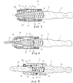
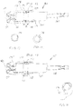
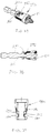
- the bit holder 10 includes a body 12 and retraction collar 14 slidably mounted on the body and retained in place by a sleeve bushing 32, as illustrated in Figure 2 .
- the body 12 can include a hex or polygonal-shaped shank 16 for mounting the bit holder 10 for rotation by a hand tool or a power tool.
- the body 12 also includes a hex or polygonal-shaped socket or bore 20 with the bore 20 opening axially outwardly toward the front or forward end of the bit holder 10.
- a plunger bore 22 extends axially from the hex-shaped socket or bore 20 toward the rear end of the bit holder assembly 10.
- an ejection spring 24 can be disposed in the plunger bore 22.
- the body 12 includes an angular slot 26 formed transversely therein, with the slot 26 extending from the radially outer surface of the body 12 in an axially forward and radially inward direction to communicate with the interior of the hex bore or socket 20.
- a coil spring 30 surrounds a portion of the body 12 and is disposed between the body 12 and the retraction collar 14.
- the coil spring 30 abuttingly engages a clip 44 which is received in a groove around a mid-portion of the body 12 and terminates in an integrally formed clip 34 that is disposed in the angular slot 26 and is designed to releasably engage a recess 38 in a hex or polygonal-shaped bit tip 40 as illustrated in Figure 3 .
- An internal annular sleeve 32 attaches to the rear portion of the retraction collar 14.
- the sleeve 32 can be secured to the collar 14 by adhesive, a press fit, thermal bonding, fasteners, pins, or other known attachment techniques.
- a clip 44 Received in a groove around a mid-portion of the body 12 is a clip 44 that acts as a stop against the sleeve 32 to limit forward travel of the retractable collar 14.
- the retractable collar 14 includes a forward shoulder portion 48 that, when pulled rearward, can engage the spring 30 and pull the clip portion 34 of the spring 30 pulling it rearward out of engagement with a bit 40 received in the hex-shaped cavity 20.
- the retractable collar 14 is of a non-magnetic material with the exception of a magnetic tip 50 that can be in the form of a ring magnet.
- Alternative magnetic arrangements can be used including multiple non-ring shaped magnets combined to form a ring-like shape mounted at the tip of the collar 14. Both faces and the internal bore of the magnet, however, may remain accessible.
- the collar 14 starts in a neutral position with the collar biased forward and the spring clip 34 extending into the bore 20.
- a bit 40 is inserted into the bore 20 so that the spring clip 34 engages a notch 38 in the side of the bit 40 to prevent removal of the bit 40 from the bore 20.
- the bit 40 also compresses the ejection spring 24.
- the retraction collar 14 remains in the neutral position.
- the collar 14 floats as a result of the magnetic force radiating from the outer face to a forward position until the outer face of the magnet 50 reaches the fastener, enabling the outer face of the ring magnet 50 to magnetically adhere to the screw 54. This occurs before the bearing sleeve 32 engages the stop ring 44.
- the magnetic force generating from the inner face of the magnet 50 by design, then draws the fastener 54 and the sleeve 14 jointly towards the body 12, the material of which it is made exhibiting magnet attractable properties resulting in holding the fastener 54 tight against the bit 40.
- the outer face of the magnet 50 also provides a stable surface to reduce movement of the fastener (wobble) during installation.
- the surface geometry of the face of the magnet 50 being such as to provide support to fasteners of multiple sizes, shapes, and configurations.
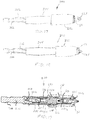
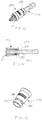
- the bit holder 60 includes a body 62 and a retraction collar assembly 64 mounted thereon.
- the body 62 includes a hex shank 66 and a hex-shaped socket or bore 70 formed in the body 62, with the bore 70 opening axially outwardly toward the front or forward end of the bit holder assembly 60.
- a plunger bore 72 extends axially from the hex-shaped socket or bore 70 toward the rear end of the bit holder assembly 60.
- an ejection spring 74 can be disposed in the plunger bore 72.
- the body 62 includes an angular slot 76 similar to the slot 26 as described above.
- a coil spring 80 having an integral spring clip 84 surrounds the body 62 and is disposed between the body and the clip 84 such that the spring clip 84 is disposed in the angular slot 76 for engaging a bit tip 40 in the manner as discussed above with regard to the previous embodiment.
- the retraction collar assembly 64 includes a rear collar 64a, an intermediate collar 64b and a forward collar 64c.
- a retainer clip 86 is disposed in a recessed groove in the outer surface of the body 62 and is disposed against a forward facing shoulder 88 of the rearward collar 64a.
- the intermediate collar 64b is press fit onto the rearward collar 64a to trap the retainer clip 86 therebetween.
- a rearward facing shoulder 90 is provided in a forward direction from the spring 80 on the intermediate collar 64b.
- the forward collar 64c is slidably supported on a forward end of the intermediate collar 64b and includes a magnetic tip 50 in the form of a magnet ring.
- the forward collar 64c acts as a floating sleeve and includes a rearward shoulder portion 90 that engages a forward shoulder portion 92 of the intermediate collar 64b to limit the forward travel of the forward collar 64c.
- the rear end of the forward collar 64c can be stretched over the forward end of the intermediate collar 64b to complete the collar assembly 64. Slots can be provided in the rear end of the forward collar 64c to facilitate assembly on the intermediate collar 64b.
- the collar could be retained through the usage of a spring ring mounted in a groove on the OD of the intermediate collar 64b and a mating taper and groove in the ID of the forward collar 64c.
- a bit tip 40 can be inserted into the hex-shaped bore 70 of the bit holder body 62.
- the spring clip 84 engages a recess 38 in the bit tip 40 in order to retain the bit tip 40 within the bore 70.
- the forward collar 64c is able to float in a forward direction to engage a fastener that is engaged by the bit tip 40 in order to magnetically retain the fastener to the bit tip 40.
- the retraction collar 64 can be pulled in a rearward direction so that rearward facing shoulder 94 of intermediate collar 64c pulls rearward on the spring 80 to disengage the spring clip portion 84 from the recess 38 in the bit tip 40.
- the magnetic sleeve on this bit holder 60 works just like the other in that it grabs the screw and pulls it back towards the body 62 and against the bit while reducing wobble.
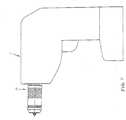
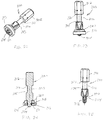
- the bit holder 10, 60 can be mounted to a drill 2 as shown in Figure 8 by inserting the hex-shaped shank 16, 66 into a chuck device.
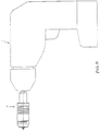
- the bit holder of the present disclosure can be integrally constructed into the chuck device of the power tool 2, as shown in Figure 9 .
- the present disclosure discloses a spring clip 34, 84 that is integral with the spring 30, 80, other arrangements of spring clips that are separate from the coil spring have also been utilized and can be utilized with the present disclosure. Examples of other arrangements include U.S. Patent Nos.
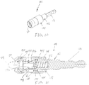
- the bit holder 110 includes a body 112 and a retraction collar 114 slidably mounted on the body 112 and retained in place by a sleeve bushing 132, as illustrated in Figure 11 .
- the body 112 can include a hex or polygonal-shaped shank 116 for mounting the bit holder 110 for rotation by a hand tool or a power tool.
- the body 112 also includes a hex or polygonal-shaped socket or bore 120 with the bore 120 opening axially outwardly toward the front end of the bit holder 110.
- a plunger bore 122 extends axially from the hex-shaped socket or bore 120 toward the rear end of the bit holder assembly 110.
- an ejection spring 124 can be disposed in the plunger bore 122.
- the body 112 includes an angular slot 126 formed transversely therein, with the slot 126 extending from the radially outward surface of the body 112 in and axially forward and radially inward direction to communicate with the interior of the hex bore or socket 120.
- a coil spring 130 surrounds a portion of the body 112 and is disposed between the body 112 and the retraction collar 114.
- the coil spring 130 abuttingly engages a clip 144 which is received in a groove 145 around a mid-portion of the body 112 and terminates as an integrally formed clip 134 that is disposed in the angular slot 126 and is designed to releasably engage a recess 38 in a hex or polygonal-shaped bit tip 40 in the same manner as the embodiment illustrated in Figures 3 and 4 .
- the internal annular sleeve 132 attaches to the rear portion of the retraction collar 114.
- Sleeve 132 can be secured to the collar 114 by adhesive, a press fit, thermal bonding, fasteners, pins, or other known attachment techniques.
- the clip 144 acts as a stop against the sleeve 132 to limit for travel of the retractable collar 114.
- Retractable collar 114 includes a forward shoulder portion 148 that when pulled rearward can engage the spring 130 and pull the clip portion 134 of the spring 130, pulling it rearward out of engagement with a bit 40 received in the hex-shaped cavity 120.
- Retractable collar 114 supports a removable magnet ring 150 that is supported by a removable sleeve 152.
- Removable sleeve 152 is secured to the retractable collar 114 by a retainer such as an O-ring or bull nose ring 154 that is received in a groove in a forward portion thereof.
- the sleeve 152' is press fit over top of the retainer ring in order to releasably secure the sleeve 152 to the retraction collar 114.
- bit tip holder 110 The operation of the bit tip holder 110 as described is the same as the bit tip holder 10 as described above.
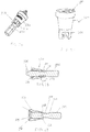
- a bit holder 160 including a hex-shaped or polygonal-shaped shank 162 and a body portion 164 including a hex-shaped or polygonal-shaped bore 166 in an end thereof for receiving a bit 40.
- the outer surface of the body 164 is provided with an elongated annular recess 168.
- a floating sleeve 170 is provided on the end of the body 164 and supports a ring magnet 50 at an end thereof.
- the floating sleeve 170 includes an interior annular groove 172 that receives a retainer 174 therein.
- the floating sleeve 170 can be removably attached to the body 164 by force fitting the body 164 into a rear opening 176 of the floating sleeve 170 until the retainer 174 is received in the recess 168 of the body 164.
- the recess 168 is provided with a forward shoulder 178 and a rearward shoulder 180 that allow the floating sleeve 170 to travel in a forward and rearward direction as indicated by arrow A while the shoulders 178 and 180 limit the travel of the floating sleeve 170 by engagement with the retainer member 174.
- the retainer 174 can take the form of a steel hog ring, as shown in Figure 13 , or a rubber O-ring as shown in Figure 14 .
- the bit holder 160' can use an alternative retainer in the form of a ball 190 which can be received in an opening 192 in the floating sleeve 170' and can be retained therein by an annular spring band 194 that can be made of steel or plastic or other suitable material.
- the bit holder 160, 160' can be used to engage a fastener via the tool bit 40 and the floating sleeve 170, 170' allows the ring magnet 50 to move forward under its magnetic force to engage the fastener and magnetize the fastener to improve the retention of the fastener with the tool bit 40.
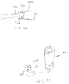
- the bit holder 200 can be configured as a six-in-one rotary tool that includes a floating ring magnet 50.
- the tool holder 200 includes a shank 202 that is integral with, and that extends rearwardly from a socket 204.
- Shank 202 is preferably hex-shaped or polygonal and includes a circumferential groove 206.
- the tool socket 204 includes a bore 208 that extends axially from the socket end and that is also preferably hex-shaped or polygonal.
- a reversible bit assembly 210 is received in the bore 208 and includes a sleeve 212 having a pair of axial storage cavities 216, 218 separated by a web 220.
- the sleeve 212 receives a first and a second bit driver 222, 224 therein.
- the outer surface of the sleeve 212, each of the cavities 216, 218, as well as a center section of the first and second bit drivers 222, 224 are each again preferably hex-shaped or polygonal such that each of the bit drivers 222, 224 rotate with the sleeve 212 and socket 204.
- Each of the first and second bit drivers 222, 224 are reversible within their respective cavities such that either of the bit ends 22a, 22b, 224a, 224b of the first and second bit drivers 222, 224 can extend from the sleeve 212. Additionally, sleeve 212 is reversible within the socket bore 208 such that either the first or second bit drivers 222, 224 operably extend from the socket 204. Accordingly, the tool may be configured such that any of the four bit driver ends 222a, 222b, 224a, 224b operably project from the socket 204.
- Either of the bit drivers 222, 224 may be removed from the sleeve 212 to expose the hex-shaped cavity 216, 218 for use as a nut driver.
- the tools sixth driver is provided by removing the reversible bit assembly 210 from the socket bore to expose the hex-shaped bore 208 for use as a second nut driver.
- the bore 208 is larger than the cavities 216, 218 thereby providing the ability to accommodate larger hex-shaped screw heads or nuts.
- the bore 208 is a 5/16 inch hex-opening while the cavities 216, 218 are each 1 ⁇ 4 inch hex openings.
- the outer surface of the socket 204 can be provided with an elongated annular recess 228 that can be engaged by a retainer 230 of a floating sleeve 232 that supports a ring magnet 50 at a forward end thereof. Accordingly, as the tool holder 200 is used to engage a fastener, one of the bit drivers 222, 224 engage the fastener and the floating sleeve 232 allows the ring magnet 50 to move in a forward direction to engage the fastener to secure the fastener to the bit driver 222, 224.
- the floating sleeve 232 can be removed by applying a slight force in a forward direction to overcome the retaining force of the retainer 230 within the elongated annular recess 228. Upon removal of the floating sleeve 232, the reversible bit assembly 210 can be removed from the socket 204 so that the bit drivers 222, 224 can be chosen for use.
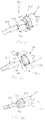
- a pivotal/rigid accessory 250 for power and hand tools includes a drive component 252 adapted to be connected to a power tool or hand tool and a driven component 254 that is pivotally connected to the drive component 252.
- a locking sleeve 256 is provided for securing the driven component 254 for non-pivotal movement relative to the drive component 252, or the locking sleeve 256 can be moved to a disengaged position that allows the driven component 254 to pivot relative to the drive component 252.
- a pivot mechanism of this type is disclosed in U.S. Patent No. 7,942,426 .
- a floating sleeve 260 can be provided at the forward end of the driven component 254 and supports a magnetic ring 50 at a forward end thereof to aid in retaining a fastener on a bit 40 received in a hex-shaped bore in the driven component 254.
- the floating sleeve can include a retainer 262 that can be received in an elongated annular recess 264 on the outer surface of the driven component 254 to allow the floating sleeve 260 to move in a forward and rearward axial direction as indicated by arrow A.
- the ring magnet 50 can be secured to the front end of the locking sleeve 256' which can be allowed to float in a forward direction to allow the ring magnet 50 to engage a fastener secured to the tool bit 40 received in a bore in the driven component 254 of the tool holder.
- Figure 21 illustrates the pivoting arrangement between the driving component and the driven component which, again, is detailed in U.S. Patent No. 7,942,426 .
- the tool bit 300 includes a shaft having a hex-shaped shank 302 at a first end, and a working region 304 disposed at a second end.
- the shaft can have a section between the hex-shaped shank 302 and the working region 304 that has a reduced diameter region 306 that is disposed between two shoulders 308, 310.
- the reduced diameter region 306 provides a torsion zone that allows the shaft to twist to absorb forces while the tool bit 300 is being used to drive a fastener.
- a tool bit 300 having a torsion zone of this type is generally known in the art as disclosed by U.S. Patent No. 5,704,261 .
- the working region 304 of the tool bit 300 can be provided with various types of drive heads such as Phillips, flat, hex, square, and other known types of drive heads.
- a recessed groove 312 is provided in the working region 304 for receiving a retainer ring 314 therein.
- a ring magnet 50 is supported by a sleeve 316 that is retained on the tool bit 300 by the retainer ring 314 that is received within the recessed groove 312.
- the floating sleeve 316 is moved in a forward direction to allow the ring magnet 50 to engage the fastener to assist in retaining the fastener to the tool bit 300.
- the floating sleeve 316 includes an interior shoulder 318 that engages the retainer 314 to limit the sleeve's forward axial travel.
- the tool bit 300 includes a shoulder 320 at an end of the working region 304 that limits the axial travel of the floating sleeve 316 in the opposite direction.
- the floating sleeve 316 can optionally be removed from the tool bit 300 by pulling on the floating sleeve 316 in an axial direction to overcome the retainer 314.
- the retainer 314 can be a rubber O-ring or a steel hog ring that can be flexed inward when the floating sleeve 316 is either inserted onto or pulled off of the tool bit 300.
- the ring magnet 50 is supported by a floating sleeve 330 that is slidably received on a forward end of the tool bit 300.
- the floating sleeve 330 includes a plurality of axially extending fingers 332 that are integrally formed with the sleeve 330 and releasably engage the reduced diameter region of the tool bit between the two shoulders 308, 310.
- Figure 28 illustrates the floating sleeve 330 in a rearward position
- Figure 29 illustrates the floating sleeve 330 in a forward position for the ring magnet 50 to engage a fastener to help retain the fastener on the tool bit 300.
- the floating sleeve 330 can be removed from the tool bit by pulling forward on the floating sleeve 330, thus causing the fingers 332 to flex radially outward over top of the increased diameter portion at the head 304 of the tool bit 300.
- the floating sleeve 330 can be made from plastic, rubber, or other materials that allow flexibility of the fingers 332.
- the ring magnet 50 can be secured to the floating sleeve 330 by adhesives, in-molding, or other known fastening techniques.
- an alternative floating sleeve 340 design is shown for supporting a ring magnet 50 that can be received on a tool bit 300.
- the sleeve 340 includes a first end 342 supporting the ring magnet 50 and a second end 344 including a single elongated slot 346 that allows the second end 344 of the sleeve 340 to flex outward for insertion of a tool bit 300 therein.
- the interior of second end 344 of the sleeve 340 includes a plurality of radially inwardly extending tabs 348 that are received in the reduced diameter portion 306 of the tool bit 300 and engage the forward and rearward shoulders 308, 310 to limit axial movement of the sleeve 340 along the length of the tool bit 300.
- the floating sleeve 340 can be made from plastic or rubber
- a floating sleeve 350 can include a plastic cup 352 that receives the ring magnet 50 at a forward end thereof and a rubber sleeve 354 at a rearward end thereof.
- the interior surface of the rubber sleeve 354 includes a plurality of radially inwardly extending tabs 356 at its rearward end, as illustrated in phantom in Figure 31 .
- the radially inwardly extending tabs 356 are flexible to allow a tool bit 300 to be inserted into the sleeve 350 so that the tabs 356 engage the reduced diameter portion 306 between the forward and rearward shoulders 308, 310 of the tool bit 300.
- the sleeve 350 is allowed to float in a forward and rearward direction in the manner as described with regard to the above described embodiments and examples.
- an alternative floating sleeve 360 design is provided in which a floating ring magnet 50 is supported at a first end of a rubber sleeve 360.
- the second end of the sleeve includes a plurality of radially inwardly extending tabs 362 that are flexible to allow a tool bit 300 to be inserted into the sleeve 360 wherein the tabs 362 are disposed in the reduced diameter portion 306 between the forward and rearward shoulders 308, 310 of the tool bit 300.
- the ring magnet 50 can be reinforced with a metal or plastic cap 364 disposed between the ring magnet 50 and the first end of the rubber sleeve 360.
- an alternative floating sleeve 370 is provided for supporting a ring magnet 50 in a forward end 372 thereof.
- the floating sleeve 370 can be made from plastic and can include one or more flexible fingers 374 that engage the reduced diameter portion 306 of the tool bit 300 between the forward and rearward shoulders 308, 310 thereof.
- the fingers 374 can include a radially inwardly protruding end portion 376 that engages the reduced diameter portion 306 of the tool bit 300.
- the elongated fingers 374 are integrally formed with the plastic sleeve 370 to allow the fingers 374 to flex radially outward when a tool bit 300 is inserted therein or removed therefrom.
- FIG. 37-39 an alternative arrangement of a floating sleeve 380 is provided wherein the flexible fingers 382 are made from a spring steel and are separately attached to the floating sleeve 380 which can be made from plastic or metal.
- the flexible fingers 382 operate in the same manner as the fingers 374 disclosed in Figures 33-36 to retain the floating sleeve 380 onto a tool bit 300 while allowing the sleeve 380 to float in a forward and rearward direction until the fingers 382 engage the forward or rearward shoulders 308, 310 of the tool bit 300.
- the fingers 382 include radially inwardly protruding portions 384 that engage the reduced diameter portion 306 of the tool bit 300.
- the flexible fingers 382 can be secured to the sleeve 380 by a rivet 386 or can be in-molded into the sleeve 380.
- the sleeve 380 includes a pair of opposing windows 388 to receive the fingers 382.
- an alternative floating sleeve 390 is provided for supporting a ring magnet 50 in a forward end thereof.
- the floating sleeve 390 can be made from plastic, rubber, or metal and can include a recessed annular groove 392 on an exterior surface thereof as well as a pair of oppositely disposed windows 394 that extend from the groove 392 into the interior of the sleeve 390.
- a rubber O-ring or a hog ring 396 can be provided in the annular groove 392 so as to extend into the window portion 394 of the annular sleeve 390 in such a manner that the O-ring or hog ring 396 can be received in the reduced diameter portion 306 of the tool bit 300 between the forward and rearward shoulders 308, 310 thereby retaining the floating sleeve 390 onto the tool bit 300.
- the reduced diameter portion 306 of the tool bit allows the floating sleeve 390 to move in a forward and rearward direction to allow the ring magnet 50 to engage a fastener for securing the fastener to the tool bit 300.
- FIG. 43-46 a still further alternative example of the floating sleeve 400 is shown wherein the floating sleeve 400 supports a ring magnet 50 at a forward end and includes an exterior annular groove 402 with an opening 404 on one side that communicates to the interior of the sleeve 400.
- the annual groove 402 receives a D-shaped ring 406 having a generally flat portion 408 along one side thereof that is received in the window opening 404 of the annular groove 402 so that it communicates to the interior of the sleeve 400.
- the flat portion 408 of the D-shaped ring 406, as shown in Figure 46 is received in the reduced diameter portion 306 of the tool bit 300 between the forward and rearward shoulders 308, 310 to limit the axial movement of the floating sleeve 400 in the forward and rearward directions.
- the floating sleeve 410 includes an elongated annular recess 412 on an outer surface thereof and a plurality of window openings 414 extending therethrough within the elongated annular recess 412.
- the openings 414 each receive a ball 416 therein and a spring band 418 is received within the elongated annular recess 412 over top of the balls 416 to secure the balls 416 within the openings 414.
- the balls 416 are designed to be received in the reduced diameter portion 306 of the tool bit 300 between the forward and rearward shoulders 308, 310 to limit the axial movement of the floating sleeve 410 in the forward and rearward directions.
- the spring band 418 allows the balls 414 to be pushed radially outward against the spring force of the band 418 while the head of the tool bit 300 is inserted into, or removed from, the sleeve 410.
- the balls 416 move radially inward reducing the force of the spring band 418 on the balls 414. It is intended that the balls 414 provide an interference when engaging the forward and rearward shoulders 308, 310 of the reduced diameter portion 306, but do not provide significant resistance to the floating motion of the sleeve 410 along the tool bit 300.
- an alternative floating sleeve 420 is shown utilizing a single ball 422 wherein the spring band 424 is provided with an opening 426 therein for maintaining the position of the spring band 424 relative to the ball 422 that is received in the single opening 426 of the floating sleeve 420.
- the floating sleeve 430 supports a ring magnet 50 at a forward end thereof and includes a pair of lock jaws 432 that are pivotally mounted to the floating sleeve by pivots 434.
- the lock jaws 432 each include radially inwardly extending tabs 436 that are designed to be engaged within the reduced diameter portion 306 of the tool bit 300.
- the lock jaws 432 can be pivoted to an engaged position, as illustrated in Figure 54 , and a lock collar 438 can be pulled over top of the lock jaws 432, as illustrated in Figure 56 , to secure the lock jaws 432 to the tool bit 300.
- the ring magnet 50 is supported at the forward end of the floating sleeve 430 and the lock jaws 432 limit the axial movement of the floating sleeve 430 along the tool bit 300 to allow the ring magnet 50 to float to an engaged position when the tool bit 300 is engaged with a fastener.
- the lock collar 438 can be pulled in a forward position allowing the lock jaws 432 to be pivoted radially outward so that the tool bit 300 can be removed from the floating sleeve 430.
- the lock collar 438 can be made of a flexible material, or can have a rigid outer ring with a flexible material on the interior thereof that allows the lock collar 438 to be retained on the lock jaws 432 when they are in the locked position.
- an alternative floating sleeve 440 including a ring magnet 50 at a forward end of a plastic sleeve.
- the plastic sleeve 440 has a slot 442 therein and has exterior cam surfaces 444 thereon.
- a rotating sleeve 446 is engaged with the cam surfaces 444 of the sleeve 440 and the rotating sleeve 446 can be rotated to cause plastic sleeve 440 to be retained in a radially inward direction to positively engaged the radially inwardly extending tabs 448 of the sleeve 440 within the reduced diameter portion 306 of the tool bit 300 between the forward and rearward shoulders 308, 310 thereof.
- the rotating sleeve 446 can also be rotated to an unlocking position that allows the sleeve 440 to flex outwardly sufficiently enough to allow removal of the bit 300 from the floating sleeve 440.
- a floating sleeve 454 is provided with two interior ring magnets 456, 458 (as illustrated in Figure 58 with the sleeve 454 removed) which are positioned with both poles opposing one another at approximately 10mm apart. With both poles of the ring magnets 456, 458 opposing one another, the sleeve 454 will move freely along a length of the tool bit 452 as they are captured by the non-magnetic sleeve 454.
- An O-ring 460 can optionally be placed between the two magnets 456, 458 to provide resistance to movement of the floating sleeve 454 if so desired.
- the opposing poles of the magnets 456, 458 cause the sleeve 454 to float on the bit 450 until a face of the forward magnet 458 contacts a head of a fastener that has been placed on the driving end 462 of the tool bit 450. Once that contact is made, the sleeve 454 then positions itself such that the fastener remains in place on the bit 450 during installation. Once the faster is securely started, the sleeve 454 can be drawn back onto the bit 450 if desired where it will remain during the driving and seating of the fastener.
Landscapes
- Engineering & Computer Science (AREA)
- Mechanical Engineering (AREA)
- Details Of Spanners, Wrenches, And Screw Drivers And Accessories (AREA)
Claims (3)
- Ensemble porte-embout (10, 60, 110) pour un outil rotatif, comprenant :un corps (12, 62, 112) ayant une tige (16, 66, 116) à son extrémité arrière et une douille coaxiale (20, 70, 120) formée à une deuxième extrémité pour permettre à un embout d'outil d'y être inséré, ledit corps ayant une ouverture (26, 76, 126) formée dans le corps en communication avec ladite douille ;un collier de rétraction (14, 64b, 114) disposé de manière coulissante sur ledit corps ;un ressort hélicoïdal (30, 80, 130) sollicitant le collier de rétraction vers l'avant ;un dispositif de retenue (34, 84, 134) maintenu dans un partie inférieure de ladite ouverture (26, 76, 126) formée dans le corps par un dudit collier de rétraction et dudit ressort hélicoïdal, dans lequel ledit embout d'outil est retiré par coulissement du collier de rétraction (14, 64b, 114) vers l'arrière, pour comprimer le ressort hélicoïdal (30, 80, 130) et permettre à l'élément de retenue (34, 84, 134) de rétracter l'ouverture (26, 86, 126) ; et caractérisé en ce qu'il comprend aussiun aimant annulaire (50) disposé à une extrémité avant du collier de rétraction (14, 64b, 114) pour magnétiser et mettre en prise un élément de fixation pour retenir l'élément de fixation sur l'embout d'outil, dans lequel ledit aimant annulaire (50) est fixé à un collier avant (152) reçu de manière amovible sur ledit collier de rétraction (114).
- Ensemble porte-embout selon la revendication 1, dans lequel l'aimant annulaire (50) est fixé directement audit collier de rétraction (14).
- Ensemble porte-embout selon la revendication 1, dans lequel ladite ouverture (26, 76, 126) dans le corps est une fente angulaire formée dans le corps et ledit ressort hélicoïdal (30, 80, 130) sollicite ledit élément de retenue (34, 84, 134) vers une partie inférieure de ladite fente angulaire.
Priority Applications (1)
| Application Number | Priority Date | Filing Date | Title |
|---|---|---|---|
| EP20178951.8A EP3834990A1 (fr) | 2012-02-15 | 2013-02-15 | Trépan d'outil |
Applications Claiming Priority (1)
| Application Number | Priority Date | Filing Date | Title |
|---|---|---|---|
| US201261599222P | 2012-02-15 | 2012-02-15 |
Related Child Applications (2)
| Application Number | Title | Priority Date | Filing Date |
|---|---|---|---|
| EP20178951.8A Division EP3834990A1 (fr) | 2012-02-15 | 2013-02-15 | Trépan d'outil |
| EP20178951.8A Division-Into EP3834990A1 (fr) | 2012-02-15 | 2013-02-15 | Trépan d'outil |
Publications (3)
| Publication Number | Publication Date |
|---|---|
| EP2628570A2 EP2628570A2 (fr) | 2013-08-21 |
| EP2628570A3 EP2628570A3 (fr) | 2018-02-14 |
| EP2628570B1 true EP2628570B1 (fr) | 2020-07-15 |
Family
ID=47720409
Family Applications (2)
| Application Number | Title | Priority Date | Filing Date |
|---|---|---|---|
| EP20178951.8A Pending EP3834990A1 (fr) | 2012-02-15 | 2013-02-15 | Trépan d'outil |
| EP13155401.6A Active EP2628570B1 (fr) | 2012-02-15 | 2013-02-15 | Porte-outil à changement rapide avec aimant annulaire |
Family Applications Before (1)
| Application Number | Title | Priority Date | Filing Date |
|---|---|---|---|
| EP20178951.8A Pending EP3834990A1 (fr) | 2012-02-15 | 2013-02-15 | Trépan d'outil |
Country Status (2)
| Country | Link |
|---|---|
| US (2) | US9156147B2 (fr) |
| EP (2) | EP3834990A1 (fr) |
Cited By (2)
| Publication number | Priority date | Publication date | Assignee | Title |
|---|---|---|---|---|
| TWI817700B (zh) * | 2022-09-02 | 2023-10-01 | 特典工具股份有限公司 | 扭力工具快脫裝置 |
| TWI817699B (zh) * | 2022-09-02 | 2023-10-01 | 特典工具股份有限公司 | 扭力工具快脫裝置 |
Families Citing this family (44)
| Publication number | Priority date | Publication date | Assignee | Title |
|---|---|---|---|---|
| KR101136382B1 (ko) * | 2009-12-08 | 2012-04-18 | 한국기계연구원 | 형상기억합금을 이용한 공구 홀더 및 공구 고정방법 |
| US9943946B2 (en) | 2012-02-15 | 2018-04-17 | Black & Decker Inc. | Tool bits with floating magnet sleeves |
| US10150205B2 (en) | 2012-02-15 | 2018-12-11 | Black & Decker Inc. | Fastening tools with floating magnet sleeves |
| US9227309B2 (en) | 2012-02-15 | 2016-01-05 | Black & Decker Inc. | Quick change bit holder with ring magnet |
| US9505108B2 (en) | 2012-02-15 | 2016-11-29 | Black & Decker Inc. | Bit holder with floating magnet sleeve |
| US9156147B2 (en) | 2012-02-15 | 2015-10-13 | Black & Decker Inc. | Quick change bit holder with ring magnet |
| EP2667017B1 (fr) * | 2012-05-22 | 2015-02-25 | Siemens Aktiengesellschaft | Un ensemble d'outils d'alignement dans le domaine des éoliennes pour aligner la tour et la base |
| US9597783B2 (en) * | 2013-07-02 | 2017-03-21 | Chervon (Hk) Limited | Bit assembly |
| EP2837468B1 (fr) | 2013-08-15 | 2017-07-05 | Black & Decker Inc. | Aimant flottant avec porte-embout à manchon |
| US20150075333A1 (en) * | 2013-09-19 | 2015-03-19 | Wei-Lin Chen | Wrench tool for screwdriver bits |
| TWI522213B (zh) * | 2014-01-22 | 2016-02-21 | Good Year Hardware Co Ltd | Tool head with limit block |
| DE102014101897A1 (de) * | 2014-02-14 | 2015-08-20 | Wera-Werk Hermann Werner Gmbh & Co. Kg | Futter mit Werkstückschutzhülse |
| DE102014009310A1 (de) | 2014-06-26 | 2015-12-31 | Gunter Tannhäuser | Magnetischer Halter für Schraubendreher-Einsätze (Bits) |
| CN105751136B (zh) * | 2014-12-18 | 2018-02-23 | 南京德朔实业有限公司 | 适用于批头的配件和具有该配件的批头组件 |
| US10093005B2 (en) * | 2014-07-15 | 2018-10-09 | Chervon (Hk) Limited | Bit accessory and bit assembly |
| EP3009234B1 (fr) * | 2014-08-15 | 2020-09-23 | Black & Decker Inc. | Mèches d'outils avec des manchons aimantés flottants |
| TWI501841B (zh) * | 2014-10-17 | 2015-10-01 | Chung Taan Ind Co Ltd | 接頭 |
| US20160279769A1 (en) * | 2015-03-25 | 2016-09-29 | Yavuz Arslan | Screwdriver Bit Positioning Structure |
| KR101628251B1 (ko) * | 2015-03-31 | 2016-06-09 | 계양전기 주식회사 | 전동공구 비트 교체 장치 |
| US9718174B2 (en) * | 2015-10-28 | 2017-08-01 | Chung-Yu Tsai | Hand tool assembly with magnetic securing device |
| USD789761S1 (en) | 2015-11-02 | 2017-06-20 | Black & Decker Inc. | Torsion bit |
| US20170120428A1 (en) * | 2015-11-02 | 2017-05-04 | Compass Corporation | Screwdriver bit device with a magnetic structure |
| EP3162506A1 (fr) * | 2015-11-02 | 2017-05-03 | Black & Decker Inc. | Outils de fixation avec manchons aimantés flottants |
| US10343266B2 (en) * | 2015-12-10 | 2019-07-09 | Milwaukee Electric Tool Corporation | Bit holder assembly |
| US10328554B2 (en) * | 2016-02-22 | 2019-06-25 | Malco Products, Inc. | Cleanable reversible socket and driver |
| TWM522823U (zh) * | 2016-03-01 | 2016-06-01 | Good Year Hardware Co Ltd | 起子頭之接桿結構 |
| JP6213627B1 (ja) * | 2016-07-15 | 2017-10-18 | 積水ハウス株式会社 | 雄ねじ探知具およびこれを用いた雄ねじの取り外し方法 |
| US10150206B2 (en) * | 2016-11-11 | 2018-12-11 | Ming-Hong Ko | Screwdriver tool |
| US11440167B2 (en) | 2016-12-08 | 2022-09-13 | Apex Brands, Inc. | Anti-marring bit holder |
| TWI581914B (zh) * | 2016-12-30 | 2017-05-11 | ri-xiong Xu | 能夠容置起子頭之套筒 |
| US10821522B2 (en) * | 2017-04-05 | 2020-11-03 | Giffin Tec, Inc. | Drill bit adapter tool |
| USD853808S1 (en) * | 2017-05-16 | 2019-07-16 | Milwaukee Electric Tool Corporation | Driver |
| US10953521B2 (en) | 2017-05-16 | 2021-03-23 | Milwaukee Electric Tool Corporation | Driver |
| US10792793B2 (en) * | 2017-06-30 | 2020-10-06 | Black & Decker Inc. | Tool bits with floating magnet sleeves |
| CN208262717U (zh) * | 2018-04-16 | 2018-12-21 | 南京德朔实业有限公司 | 适用于批头的接杆组件以及适用于接杆的套筒组件 |
| USD877590S1 (en) | 2018-07-20 | 2020-03-10 | Milwaukee Electric Tool Corporation | Tool accessory |
| USD966358S1 (en) | 2018-08-06 | 2022-10-11 | Giffin Tec, Inc. | Drill bit adapter |
| US11958171B2 (en) * | 2019-04-23 | 2024-04-16 | Klein Tools, Inc. | Insulated reversible screwdriver |
| EP3632205B1 (fr) | 2019-05-22 | 2021-03-17 | New Direction Tackle Ltd. | Dispositif d'accouplement rapidement démontable |
| US11383359B1 (en) | 2019-08-05 | 2022-07-12 | Matthew Andersen | Magnetic bit holder with automatic retracting guide sleeve |
| TWI730874B (zh) * | 2020-08-18 | 2021-06-11 | 薪螢企業有限公司 | 快脫式工具接桿 |
| USD955453S1 (en) * | 2020-10-01 | 2022-06-21 | Shukla Medical | Drill bit |
| US20220133025A1 (en) * | 2020-11-03 | 2022-05-05 | Techtronic Cordless Gp | Drive coupler for power scrubber |
| USD1000236S1 (en) | 2021-01-11 | 2023-10-03 | Diversitech Corporation | Driver for reversible socket |
Citations (1)
| Publication number | Priority date | Publication date | Assignee | Title |
|---|---|---|---|---|
| DE202005013315U1 (de) * | 2005-08-23 | 2005-10-27 | Chang, Sheng-Ming, Daya | Schraubwerkzeug |
Family Cites Families (200)
| Publication number | Priority date | Publication date | Assignee | Title |
|---|---|---|---|---|
| US1124981A (en) | 1913-02-20 | 1915-01-12 | William Arthur Weaver | Tool-holder. |
| US1119276A (en) | 1913-12-08 | 1914-12-01 | Raymond W Griffith | Chuck. |
| US1138465A (en) | 1914-11-19 | 1915-05-04 | North Bros Mfg Co | Chuck. |
| US1656450A (en) | 1925-02-28 | 1928-01-17 | Steuer August | Chuck |
| US1860998A (en) | 1931-08-21 | 1932-05-31 | Drazick John | Tool holder |
| US2348611A (en) | 1942-06-12 | 1944-05-09 | Davidson Cecil Stanley | Clamp for holding drill rods or casings |
| US2409899A (en) | 1944-06-08 | 1946-10-22 | Manuel S Resina | Cap chuck |
| US2522217A (en) | 1946-11-06 | 1950-09-12 | Apex Machine & Tool Company | Composite bit device for screw drivers and the like |
| US2524095A (en) | 1946-11-26 | 1950-10-03 | Robert D Powers | Screw driver with elementgripping jaws |
| US2671484A (en) * | 1948-11-18 | 1954-03-09 | Wade Stevenson | Magnetic tool |
| US2677294A (en) | 1950-11-25 | 1954-05-04 | Wade Stevenson | Magnetic driving implement |
| US2762408A (en) | 1954-09-20 | 1956-09-11 | Arthur I Baldwin | Screw head gripping attachment for screw drivers |
| US3007504A (en) | 1957-07-25 | 1961-11-07 | Wade Stevenson | Magnetic tool holder |
| US2933114A (en) | 1957-09-16 | 1960-04-19 | Agnar F Bystrom | Screw-holding screw driver |
| AT211629B (de) | 1959-05-19 | 1960-10-25 | Friedrich Pongracz | Vorschubpatrone bzw. Rückzugsperre für auf Ein- und Mehrspindelautomaten, Revolverdrehbänken, Feinmechanikdrehbänken u. dgl. Werkzeugmaschinen zu bearbeitende |
| US3398965A (en) | 1966-05-26 | 1968-08-27 | Balas Collet Company | Quick change tool holder |
| US3436086A (en) | 1966-05-31 | 1969-04-01 | Hanson Whitney Co The | Tool holder |
| GB1185370A (en) | 1967-12-18 | 1970-03-25 | Robert James Amos | A Coupling for Connecting Members for Rotation together about an Axis. |
| US3604488A (en) | 1969-11-19 | 1971-09-14 | Vermont American Corp | Screwdriver attachment |
| US3726533A (en) | 1971-01-22 | 1973-04-10 | Milwaukee Electric Tool Corp | Spring biased coupling for tool and chuck |
| US3707894A (en) | 1971-02-10 | 1973-01-02 | Gardner Denver Co | Magnetic fastener driving tool |
| US3788658A (en) | 1972-08-14 | 1974-01-29 | Erickson Tool Co | Instant change tool holder |
| DE2249234A1 (de) | 1972-10-07 | 1974-04-18 | Bosch Gmbh Robert | Schnellwechselwerkzeugaufnahme |
| US3767218A (en) | 1973-02-21 | 1973-10-23 | Carrier Corp | Tool chuck |
| US3901298A (en) | 1974-04-05 | 1975-08-26 | John B Eby | Fastener holding attachment |
| US4184692A (en) | 1977-05-23 | 1980-01-22 | The Boeing Company | Motor quick-change chuck system for tool having cylindrically shaped adapter portion |
| DE2841744A1 (de) | 1978-09-26 | 1980-04-03 | Bilz Otto Werkzeug | Schnellwechselfutter, insbesondere fuer eine das werkzeug aufnehmende stellhuelse |
| DE2934428A1 (de) | 1979-08-25 | 1981-03-26 | Wera-Werk Hermann Werner Gmbh & Co, 42349 Wuppertal | Spannfutter fuer werkzeug-einsatzstuecke, insbesondere schraubendreherbits |
| US4317578A (en) | 1979-11-07 | 1982-03-02 | Welch Thomas R | Keyless chucking system |
| JPS5959278U (ja) | 1982-10-13 | 1984-04-18 | ワイケイケイ株式会社 | 空気インパクトレンチのビツト保持機構 |
| US4577875A (en) | 1982-10-29 | 1986-03-25 | Miyakawa Industry Co., Ltd. | Exchange chuck for a tool |
| DE3243389C2 (de) | 1982-11-24 | 1986-05-15 | Wera Werk Hermann Werner Gmbh & Co, 5600 Wuppertal | Spannfutter für unrund gestaltete Schaftenden von Werkzeug-Einsatzstücken, insbesondere Schraubendreherbits |
| DE3330486A1 (de) | 1983-08-24 | 1985-03-07 | Wera Werk Hermann Werner Gmbh & Co, 5600 Wuppertal | Spannfutter fuer werkzeug-einsatzstuecke, insbesondere schraubendreherbits |
| US4588335A (en) | 1984-09-14 | 1986-05-13 | Pearson Jr Claude C | Quick change tool retention device for power operated mechanism |
| US4692073A (en) | 1985-02-25 | 1987-09-08 | Martindell J Richard | Handle adapter and chuck apparatus for power bits |
| US4669932A (en) | 1985-05-24 | 1987-06-02 | Wayne Hartley | Keyless tool chuck |
| DE3636027A1 (de) | 1986-10-23 | 1988-04-28 | Hilti Ag | Handgeraet mit loesbarem werkzeughalter |
| US4858939A (en) | 1987-02-09 | 1989-08-22 | The Aro Corporation | Bit retention and release mechanism |
| DE3907567A1 (de) | 1988-03-10 | 1989-09-28 | Werner Hermann Wera Werke | Schraubendrehereinsatz |
| US4787278A (en) | 1988-03-30 | 1988-11-29 | Western Pacific Industries Inc. | Tool bit driver with spring retainer |
| FR2631275A1 (fr) | 1988-05-16 | 1989-11-17 | Fassetta Sa F | Dispositif de cle a fonctions multiples a reglages alternes et independants pour le serrage des ecrous et des vis a bois ou similaires |
| US5013194A (en) | 1988-09-08 | 1991-05-07 | Wienhold James L | Chuck assembly for tool bits |
| US5012708A (en) | 1989-08-07 | 1991-05-07 | Martindell J Richard | Depth locator apparatus for insert bit holders |
| US5182973A (en) | 1988-10-13 | 1993-02-02 | Martindell J Richard | Depth locator apparatus for insert bit holders |
| US5062749A (en) | 1989-02-21 | 1991-11-05 | Sheets Harold D | Tool coupler |
| US5056387A (en) | 1989-08-11 | 1991-10-15 | Cook Chester L | Screw-holding screwdriver |
| US5188378A (en) | 1990-01-11 | 1993-02-23 | Wera Werk Hermann Werner Gmbh & Co. | Chuck for polygonal shank ends of tools |
| US5181438A (en) | 1990-04-10 | 1993-01-26 | Aip Inc. | Ball lock punch retainer |
| US5152642A (en) | 1991-06-12 | 1992-10-06 | Hextap, Inc. | Metal injection molded rotary metal cutting tool |
| DE4243608C2 (de) | 1992-12-22 | 2000-10-19 | Werner Hermann Wera Werke | Werkzeug |
| DE4243650C2 (de) | 1992-12-23 | 1996-07-25 | Schmidt Ulrich Ush Schraubwerk | Spannfutter für Werkzeug-Einsatzstücke |
| US5385420A (en) | 1993-08-03 | 1995-01-31 | Newman, Sr.; Robert D. | Coupling assembly |
| US5398946A (en) | 1993-12-29 | 1995-03-21 | Poly-Tech Industries | Chuck having one-step lock and release |
| EP0741633B1 (fr) | 1994-01-26 | 1998-12-16 | Vermont American Corporation | Lame pour un tournevis a moteur |
| US5577426A (en) | 1994-11-08 | 1996-11-26 | Snap-On Technologies, Inc. | Magnetic bit holder and hand tool incorporating same |
| JP3091663B2 (ja) | 1995-02-28 | 2000-09-25 | 日東精工株式会社 | ビット |
| JP3423497B2 (ja) | 1995-09-06 | 2003-07-07 | 株式会社マキタ | 携帯工具のビット装着装置 |
| DE19536154A1 (de) | 1995-09-28 | 1997-04-03 | Hilti Ag | Werkzeughalter für Bohr- und Meisselwerkzeuge |
| US6082233A (en) | 1996-06-21 | 2000-07-04 | Han; Ki Su | Fastener holding device |
| US5724872A (en) | 1996-06-28 | 1998-03-10 | Shih; Leo | Socket spanner having a nut retaining device |
| US5724873A (en) * | 1996-07-12 | 1998-03-10 | Hillinger; George | Composite magnetic-field screwdriver |
| US5992274A (en) | 1996-11-27 | 1999-11-30 | Construction Fasteners, Inc. | Installation tool for pre-assembled screw and plate assemblies |
| WO1998055268A1 (fr) | 1997-06-02 | 1998-12-10 | Wera Werk Hermann Werner Gmbh & Co. | Mandrin de serrage pour embouts ou autres |
| US5951024A (en) | 1997-08-11 | 1999-09-14 | Power Tool Holders Incorporated | Enhanced grip tool holding chuck |
| US6148699A (en) | 1997-08-26 | 2000-11-21 | Han; Ki Su | Screwdriver and screw |
| US5934384A (en) | 1998-04-27 | 1999-08-10 | Wang; Peter | Transmission shaft and bit mounting arrangement of a motor-driven hand drill |
| DE19821270A1 (de) | 1998-05-13 | 1999-11-18 | Otto Bilz, Werkzeugfabrik Gmbh & Co | Futter für drehantreibbare Werkzeuge, insbesondere Bohrer, Gewindebohrer o. dgl. |
| US6053675A (en) | 1998-06-26 | 2000-04-25 | Black & Decker Inc. | Quick-acting tool bit holder |
| JP3285823B2 (ja) | 1998-07-09 | 2002-05-27 | 株式会社ベッセル工業 | ドライバービットのねじ保持具 |
| US6126370A (en) | 1998-07-22 | 2000-10-03 | Black & Decker Inc. | Removable tool holder |
| US5996452A (en) | 1998-10-13 | 1999-12-07 | Chiang; Shu Chi | Chuck device for power tool |
| JP2000127058A (ja) | 1998-10-20 | 2000-05-09 | Nippon Comsys Corp | ドライバー |
| ATE396812T1 (de) | 1998-11-12 | 2008-06-15 | Black & Decker Inc | Futter, bohrer, zusammenbau dafür und montagemethode |
| US5988957A (en) | 1998-12-21 | 1999-11-23 | Black & Decker Inc. | Quick clamp |
| JP3688506B2 (ja) * | 1999-02-09 | 2005-08-31 | 株式会社マキタ | 磁気吸着式ドライバー |
| GB9907468D0 (en) | 1999-03-31 | 1999-05-26 | Black & Decker Inc | Drill/driver chuck |
| US6543959B1 (en) | 1999-04-13 | 2003-04-08 | Jore Corporation | Two-way quick connector |
| DE60013812T2 (de) | 1999-05-03 | 2005-11-17 | Maxtech Mfg. Inc., Waterloo | Schnellkupplung |
| US6074140A (en) | 1999-07-09 | 2000-06-13 | Banner American Products, Inc. | Quick-release chuck assembly |
| DE19932369B4 (de) | 1999-07-13 | 2013-09-26 | Wera-Werk Hermann Werner Gmbh & Co. Kg | Futter für Schraubendrehereinsätze |
| ATE418410T1 (de) | 1999-07-21 | 2009-01-15 | Black & Decker Inc | Angetriebenes futter |
| CN1331628C (zh) | 1999-07-21 | 2007-08-15 | 布莱克-德克尔公司 | 动力驱动夹头 |
| US6199872B1 (en) | 1999-08-13 | 2001-03-13 | Maxtech Consumer Products, L.L.C. | Quick-release mechanism for screwdriver bits and the like |
| US6270085B1 (en) | 1999-10-01 | 2001-08-07 | Tsai-Ching Chen | Chuck device for tool bits |
| US6325393B1 (en) | 1999-10-01 | 2001-12-04 | Tsai-Ching Chen | Chuck device for tools |
| US6154108A (en) | 1999-10-07 | 2000-11-28 | Huang; Li Shiu | Fastener attracting device for tool |
| US6457916B2 (en) | 1999-11-15 | 2002-10-01 | Insty-Bit, Inc. | Locking quick-change chuck assembly |
| KR100601835B1 (ko) | 1999-12-30 | 2006-07-19 | 한라공조주식회사 | 자동차용 공기조화장치 |
| DE10001191C2 (de) | 2000-01-14 | 2002-04-04 | Bosch Gmbh Robert | Handwerkzeugmaschine mit einer schlagend und/oder drehend antreibbaren Werkzeughalterung |
| DE20001825U1 (de) | 2000-02-02 | 2000-05-04 | Liu Lien Huang | Schneidwerkzeug |
| US6354177B2 (en) | 2000-02-29 | 2002-03-12 | Black & Decker Inc. | 6-in-1 rotary tool |
| US7316404B1 (en) | 2000-03-29 | 2008-01-08 | Black & Decker Inc. | Drill/driver chuck |
| WO2001096052A1 (fr) | 2000-06-09 | 2001-12-20 | Jore Corporation | Adaptateur de piece pour outil electrique |
| KR100380640B1 (ko) | 2000-09-15 | 2003-04-16 | 이홍근 | 드라이버의 나사 가이드장치 |
| US20020166421A1 (en) | 2001-05-11 | 2002-11-14 | Bowerman Jeffrey Allen | Screw driving, locking and alignment device |
| DE10148943B4 (de) * | 2001-05-17 | 2004-02-26 | Felo-Werkzeugfabrik Holland-Letz Gmbh | Schraubvorrichtung für Schraubendreher-Einsätze |
| US6622597B2 (en) | 2001-05-18 | 2003-09-23 | Su Shia Chen | Ratchel tool having longitudinally movable pawls |
| US20030025326A1 (en) | 2001-07-25 | 2003-02-06 | The Coleman Company, Inc. | Sliding coupling for gas appliances |
| US6651990B2 (en) | 2001-08-06 | 2003-11-25 | Ryobi Ltd. | Tool holder |
| DE10141668A1 (de) | 2001-08-25 | 2003-03-06 | Werner Hermann Wera Werke | Spannfutter für Werkzeuge, insbesondere Schraubendreherbits |
| DK200101378A (da) | 2001-09-22 | 2002-04-27 | Oticon As | Screw and screwdriver |
| US6834864B2 (en) | 2001-10-24 | 2004-12-28 | Power Tool Holders Incorporated | Chuck having quick change mechanism |
| WO2003035330A1 (fr) | 2001-10-26 | 2003-05-01 | Black & Decker Inc | Porte-outil |
| US6530299B1 (en) | 2001-11-20 | 2003-03-11 | Tsai-Fa Liu | Joint adapter for a power drill screw driver |
| US6698319B2 (en) | 2002-02-04 | 2004-03-02 | Li Shiu Huang | Tool retaining device for retaining various tools |
| US6637755B2 (en) | 2002-03-22 | 2003-10-28 | Tsai-Ching Chen | Chuck device for miniature tool bits |
| JP2003311641A (ja) | 2002-04-24 | 2003-11-05 | Nagahori Kogyo Kk | ドライバービット用のネジ保持アタッチメントとこれを装着したドライバービット |
| US6684740B2 (en) | 2002-04-26 | 2004-02-03 | Ching Chou Lin | Magnetic device for retaining tool members to drivers |
| WO2003103901A2 (fr) | 2002-06-10 | 2003-12-18 | Wera Werk | Mandrin pour la reception d'outils utilisables par rotation autour de leur axe |
| US6929266B2 (en) | 2002-06-18 | 2005-08-16 | Black & Decker Inc. | Bit holder |
| DE10233866B4 (de) | 2002-07-25 | 2018-01-25 | Wera Werk Hermann Werner Gmbh & Co. Kg | Schraubwerkzeug mit austauschbarem Schaft |
| JP2004106473A (ja) | 2002-09-20 | 2004-04-08 | Max Co Ltd | コンクリートドリル等におけるコアビット着脱機構 |
| EP1549226A4 (fr) | 2002-09-26 | 2006-05-10 | Bioaccess Inc | Dispositif medical orthopedique a composants unitaires |
| CA2407908A1 (fr) | 2002-10-11 | 2004-04-11 | Li Kun Bai | Outil multiple de perceuse |
| US20040093997A1 (en) | 2002-11-15 | 2004-05-20 | Huang Li Shiu | Tool extension with a screw attraction structure |
| US6863280B2 (en) | 2002-11-20 | 2005-03-08 | Li Jiun Chiu | Tool fixing structure |
| US6666114B1 (en) | 2003-01-27 | 2003-12-23 | Lin Peng-Ho | Magnetic connecting tube for a screwdriver head |
| US20040164503A1 (en) | 2003-02-21 | 2004-08-26 | Wei-Chuan Fan-Chiang | Bit quick-release device |
| DE20303601U1 (de) | 2003-03-05 | 2003-05-08 | Quanz Reiner | Bohrwerkzeug |
| US6860489B2 (en) | 2003-03-31 | 2005-03-01 | Tsai-Ching Chen | Chuck device |
| US6874791B2 (en) | 2003-05-23 | 2005-04-05 | Tsai-Ching Chen | Chuck apparatus |
| US6840143B1 (en) | 2003-06-20 | 2005-01-11 | Ying-Mo Lin | Adapter for screwdriver having elastic retainer ring |
| WO2005000530A1 (fr) | 2003-06-25 | 2005-01-06 | Vessel Industrial Co., Ltd. | Dispositif de maintien de meche |
| WO2005017368A2 (fr) | 2003-08-18 | 2005-02-24 | Felo-Werkzeugfabrik Holland-Letz Gmbh | Dispositif magnetique de maintien de vis |
| US6973858B2 (en) | 2003-08-29 | 2005-12-13 | Jung-Chih Huang | Socket assembly that can be mounted and detached quickly |
| US6986517B2 (en) | 2003-10-24 | 2006-01-17 | Lin Peng-Ho | Coupling tube for a screwdriver head |
| US20050166725A1 (en) | 2004-02-02 | 2005-08-04 | Shiu-E Chen | Fastening component assistive positioning device |
| US6931967B1 (en) | 2004-02-26 | 2005-08-23 | Sheng-Ming Chang | Connecting shaft device for screws |
| DE202004004469U1 (de) | 2004-03-22 | 2004-05-27 | Chang, Sheng-Ming, Daya | Verbindungsstück für Schraubendreher |
| US7284936B1 (en) * | 2004-04-26 | 2007-10-23 | Teleflex Medical Incorporated | Tool bit and collet assembly and method |
| US20060027057A1 (en) | 2004-08-04 | 2006-02-09 | Chih-Ching Hsien | Quick release device for releasing screw bit from socket |
| US7107882B1 (en) | 2004-10-01 | 2006-09-19 | Chang Wun-Hai | Slip-resistant magnetic sheath for a screwdriver |
| US7308948B2 (en) | 2004-10-28 | 2007-12-18 | Makita Corporation | Electric power tool |
| US7096768B1 (en) | 2005-04-04 | 2006-08-29 | Hsiu E Chen | Extension rod assembly |
| US7124665B1 (en) | 2005-09-26 | 2006-10-24 | Hsiu-E Chen | Screw positioning device for a screwdriver |
| US7159493B1 (en) | 2005-11-30 | 2007-01-09 | Daniel Huang | Driving bit linking device in a box wrench |
| US7726664B2 (en) * | 2005-12-29 | 2010-06-01 | Black & Decker Inc. | Universal tool bit shank |
| US20090165606A1 (en) | 2006-01-10 | 2009-07-02 | Chih-Ching Hsien | Quick release device for releasing screw bit from socket |
| US7387054B2 (en) | 2006-03-01 | 2008-06-17 | Jacques Rajotte | Screw driving device |
| US7278342B1 (en) | 2006-03-21 | 2007-10-09 | Sheng Ming Chang | Tool connecting device |
| US20070234856A1 (en) | 2006-04-05 | 2007-10-11 | Kuo-Chen Liu | Magnetic connecting tube for a screwdriver head |
| EP2013440B1 (fr) * | 2006-04-13 | 2016-03-09 | INSTY-BIT, Inc. | Porte-meche d'outil automatique |
| US7942426B2 (en) | 2006-07-12 | 2011-05-17 | Black & Decker Inc. | Pivotal/rigid accessories for power and hand tools |
| US7290470B1 (en) * | 2006-07-19 | 2007-11-06 | Black & Decker Inc. | Multi-bit driver with rotatable sleeve |
| US7669860B2 (en) | 2006-07-27 | 2010-03-02 | Hsin Ying Enterprise Co., Ltd. | Tool retaining or connecting device |
| US7597031B2 (en) * | 2006-08-03 | 2009-10-06 | Wen Hung Chiang | Driving tool having rotatable coupling |
| US7306396B1 (en) | 2006-08-08 | 2007-12-11 | Chen Bo Shen | Connector structure with a detachable mounting tube |
| TWM308146U (en) | 2006-09-25 | 2007-03-21 | Jeoutay Liu Ind Co Ltd | Structure of coupling sleeve |
| US7823890B2 (en) | 2006-11-01 | 2010-11-02 | Tsai-Ching Chen | Chuck |
| TWM313044U (en) | 2006-11-23 | 2007-06-01 | Jeoutay Liu Ind Co Ltd | Tool bit adaptor |
| US7779734B2 (en) | 2007-01-03 | 2010-08-24 | Nichols Jr Wade Hampton | Fastener drive-starter |
| US20080184853A1 (en) | 2007-02-06 | 2008-08-07 | Shiou-E Chen | Screw Positioning Sleeve Assembly |
| US20080216618A1 (en) | 2007-02-06 | 2008-09-11 | Shiou-E Chen | Screw Positioning Sleeve Assembly |
| US20080184854A1 (en) * | 2007-02-07 | 2008-08-07 | Black & Decker Inc. | Multi-Bit Drive With Drywall Dimpler |
| USD589319S1 (en) * | 2007-02-08 | 2009-03-31 | Black & Decker Inc. | Pivoting bit holder |
| JP5073321B2 (ja) | 2007-03-07 | 2012-11-14 | 株式会社マキタ | 回転工具のビット取り付け装置 |
| DE102007012892A1 (de) | 2007-03-17 | 2007-12-20 | Daimlerchrysler Ag | Werkzeug |
| US7387051B1 (en) | 2007-03-27 | 2008-06-17 | Hsin Ying Enterprise Co., Ltd. | Tool device for driving various tool members |
| US7735400B2 (en) | 2007-08-20 | 2010-06-15 | Ho-Tien Chen | Torque releasing clutch for a screw driver blade |
| US7565854B2 (en) | 2007-10-31 | 2009-07-28 | Hsin Ying Enterprise Co., Ltd. | Tool retaining device for power tool |
| US20090139378A1 (en) | 2007-11-30 | 2009-06-04 | Hsin Ying Enterprise Co., Ltd. | Driver tool having adjustable structure |
| US20090139379A1 (en) | 2007-11-30 | 2009-06-04 | Hsin Ying Enterprise Co., Ltd. | Driver tool for driving various tool members |
| US20090174157A1 (en) | 2008-01-08 | 2009-07-09 | Hsin Ying Enterprise Co., Ltd. | Tool connecting device |
| DE202008003131U1 (de) | 2008-03-05 | 2008-09-04 | Rajotte, Jacques, Hood River | Schraubendrehervorrichtung |
| US7574946B1 (en) | 2008-03-19 | 2009-08-18 | Chang Wun-Hai | Magnetic assembly of a screwdriver head rod |
| US20090288525A1 (en) | 2008-05-21 | 2009-11-26 | Shiou-E Chen | Screw positioning sleeve assembly |
| TW200950934A (en) | 2008-06-11 | 2009-12-16 | Hou-Fei Hu | Chuck for bit |
| TW200950938A (en) | 2008-06-11 | 2009-12-16 | Hou-Fei Hu | Chuck for bit |
| US20090314143A1 (en) | 2008-06-23 | 2009-12-24 | Ho-Tien Chen | Screw band locking device |
| US20100011918A1 (en) * | 2008-07-17 | 2010-01-21 | Josh Ray | Screwdriver bit with magnetic collar |
| TW201006625A (en) | 2008-08-06 | 2010-02-16 | Hou-Fei Hu | Tool chuck for screwdriver |
| US8166851B2 (en) | 2008-08-15 | 2012-05-01 | Robert Bosch Gmbh | Combination driving tool for phillips and robertson fasteners |
| US8305980B1 (en) | 2008-09-12 | 2012-11-06 | Nix John A | Efficient handover of media communications in heterogeneous IP networks using handover procedure rules and media handover relays |
| US8418587B2 (en) | 2008-11-07 | 2013-04-16 | Milwaukee Electric Tool Corporation | Tool bit |
| USD623036S1 (en) | 2008-11-07 | 2010-09-07 | Milwaukee Electric Tool Corporation | Insert bit |
| USD624383S1 (en) | 2009-03-01 | 2010-09-28 | Hsu Shao-Hsien | Tool bit |
| US8250949B2 (en) * | 2009-05-19 | 2012-08-28 | Bobby Hu | Tool assembly with coaxial/universal coupling |
| TWM367783U (en) | 2009-06-05 | 2009-11-01 | Rote Mate Industry Co Ltd | Screwdriver head with assisted positioning feature |
| US8262097B2 (en) | 2009-07-07 | 2012-09-11 | Jin-Tsai Lai | Quick-release mechanism for hand tool |
| TW201103713A (en) | 2009-07-27 | 2011-02-01 | Cai-Qing Chen | Tool with bending angle |
| US20120272795A1 (en) * | 2009-07-27 | 2012-11-01 | Tsai-Ching Chen | Hand Tool |
| TWM375810U (en) * | 2009-07-31 | 2010-03-11 | Chung Taan Ind Co Ltd | Improved structure of rapid connector |
| USD615380S1 (en) | 2009-09-09 | 2010-05-11 | Cheng-Wei Su | Tool bit |
| US9101987B2 (en) | 2009-10-08 | 2015-08-11 | Jore Corporation | Tool connector having multiple seating positions |
| KR20120082035A (ko) | 2009-11-13 | 2012-07-20 | 이안 라클란 킬패트릭 | 공작기계 비트 설계 |
| US8176817B2 (en) * | 2010-01-09 | 2012-05-15 | Kuo-Han Liu | Tool coupling structure |
| US8523873B2 (en) * | 2010-04-08 | 2013-09-03 | Warsaw Orthopedic, Inc. | Neural-monitoring enabled sleeves for surgical instruments |
| US20110283842A1 (en) | 2010-05-21 | 2011-11-24 | Rote Mate Industry Co., Ltd. | Screwdriver bit structure |
| USD646138S1 (en) | 2010-09-06 | 2011-10-04 | Hsu Shao-Hsien | Tool bit |
| TWM402172U (en) | 2010-11-23 | 2011-04-21 | Classic Tools Co Ltd | Quick-release linkage with small outer diameter |
| USD653517S1 (en) | 2010-12-09 | 2012-02-07 | Ibt Holdings, Llc | Tool bit |
| USD653096S1 (en) | 2010-12-20 | 2012-01-31 | Ibt Holdings, Llc | Tool bit |
| USD646139S1 (en) | 2011-01-26 | 2011-10-04 | Hsu Shao-Hsien | Tool bit |
| DE102011000710A1 (de) | 2011-02-14 | 2012-08-16 | Wera-Werk Hermann Werner Gmbh & Co. Kg | Drehmomentübertragungseinrichtung in Form eines Bitfutters |
| TWI362312B (en) | 2011-04-19 | 2012-04-21 | Chung Taan Ind Co Ltd | Connecting rod |
| CN202528113U (zh) | 2012-02-10 | 2012-11-14 | 峰巨有限公司 | 小外径快脱接杆 |
| US9505108B2 (en) * | 2012-02-15 | 2016-11-29 | Black & Decker Inc. | Bit holder with floating magnet sleeve |
| US9156147B2 (en) | 2012-02-15 | 2015-10-13 | Black & Decker Inc. | Quick change bit holder with ring magnet |
| US9227309B2 (en) | 2012-02-15 | 2016-01-05 | Black & Decker Inc. | Quick change bit holder with ring magnet |
| DE202013008907U1 (de) | 2013-10-07 | 2014-01-21 | Chung-Yen Ho | Kombinationsbuchse- und Schraubendreher-Aufbau |
-
2013
- 2013-02-13 US US13/766,135 patent/US9156147B2/en active Active
- 2013-02-15 EP EP20178951.8A patent/EP3834990A1/fr active Pending
- 2013-02-15 EP EP13155401.6A patent/EP2628570B1/fr active Active
-
2015
- 2015-08-27 US US14/837,105 patent/US10040179B2/en active Active
Patent Citations (1)
| Publication number | Priority date | Publication date | Assignee | Title |
|---|---|---|---|---|
| DE202005013315U1 (de) * | 2005-08-23 | 2005-10-27 | Chang, Sheng-Ming, Daya | Schraubwerkzeug |
Cited By (2)
| Publication number | Priority date | Publication date | Assignee | Title |
|---|---|---|---|---|
| TWI817700B (zh) * | 2022-09-02 | 2023-10-01 | 特典工具股份有限公司 | 扭力工具快脫裝置 |
| TWI817699B (zh) * | 2022-09-02 | 2023-10-01 | 特典工具股份有限公司 | 扭力工具快脫裝置 |
Also Published As
| Publication number | Publication date |
|---|---|
| EP2628570A2 (fr) | 2013-08-21 |
| US20150367486A1 (en) | 2015-12-24 |
| US10040179B2 (en) | 2018-08-07 |
| EP2628570A3 (fr) | 2018-02-14 |
| US20130220086A1 (en) | 2013-08-29 |
| EP3834990A1 (fr) | 2021-06-16 |
| US9156147B2 (en) | 2015-10-13 |
Similar Documents
| Publication | Publication Date | Title |
|---|---|---|
| EP2628570B1 (fr) | Porte-outil à changement rapide avec aimant annulaire | |
| US10556329B2 (en) | Tool bits with floating magnet sleeves | |
| US9227309B2 (en) | Quick change bit holder with ring magnet | |
| US9505108B2 (en) | Bit holder with floating magnet sleeve | |
| EP2837468B1 (fr) | Aimant flottant avec porte-embout à manchon | |
| US10150205B2 (en) | Fastening tools with floating magnet sleeves | |
| EP2223760B1 (fr) | Dispositif de rétention d'embout | |
| US7086813B1 (en) | Quick-acting tool bit holder | |
| US8220367B2 (en) | Transmission extension adapter for power hand tool | |
| EP2429764B1 (fr) | Connecteur à libération rapide | |
| US6347914B1 (en) | Rotary tool holder | |
| US6394715B1 (en) | Rotary tool holder | |
| US7651303B2 (en) | Conduit reamer tool element | |
| US20090139378A1 (en) | Driver tool having adjustable structure | |
| US20060254394A1 (en) | Fastener driver | |
| GB2441023A (en) | Locking chuck | |
| EP3009234B1 (fr) | Mèches d'outils avec des manchons aimantés flottants | |
| US6877937B2 (en) | Reversible drill/driver tool | |
| EP2560779A1 (fr) | Système de mandrin de scie-cloche | |
| EP3162506A1 (fr) | Outils de fixation avec manchons aimantés flottants | |
| US11440167B2 (en) | Anti-marring bit holder | |
| US20240123582A1 (en) | Double-ended quick-change tool bit holder assembly and quick-change bit driver modification |
Legal Events
| Date | Code | Title | Description |
|---|---|---|---|
| PUAI | Public reference made under article 153(3) epc to a published international application that has entered the european phase |
Free format text: ORIGINAL CODE: 0009012 |
|
| AK | Designated contracting states |
Kind code of ref document: A2 Designated state(s): AL AT BE BG CH CY CZ DE DK EE ES FI FR GB GR HR HU IE IS IT LI LT LU LV MC MK MT NL NO PL PT RO RS SE SI SK SM TR |
|
| AX | Request for extension of the european patent |
Extension state: BA ME |
|
| RIC1 | Information provided on ipc code assigned before grant |
Ipc: B25B 23/12 20060101ALI20171201BHEP Ipc: B23B 31/10 20060101ALI20171201BHEP Ipc: B23B 31/22 20060101ALI20171201BHEP Ipc: B25B 23/00 20060101AFI20171201BHEP Ipc: B23B 31/107 20060101ALI20171201BHEP |
|
| PUAL | Search report despatched |
Free format text: ORIGINAL CODE: 0009013 |
|
| AK | Designated contracting states |
Kind code of ref document: A3 Designated state(s): AL AT BE BG CH CY CZ DE DK EE ES FI FR GB GR HR HU IE IS IT LI LT LU LV MC MK MT NL NO PL PT RO RS SE SI SK SM TR |
|
| AX | Request for extension of the european patent |
Extension state: BA ME |
|
| RIC1 | Information provided on ipc code assigned before grant |
Ipc: B23B 31/22 20060101ALI20180108BHEP Ipc: B25B 23/00 20060101AFI20180108BHEP Ipc: B25B 23/12 20060101ALI20180108BHEP Ipc: B23B 31/107 20060101ALI20180108BHEP Ipc: B23B 31/10 20060101ALI20180108BHEP |
|
| STAA | Information on the status of an ep patent application or granted ep patent |
Free format text: STATUS: REQUEST FOR EXAMINATION WAS MADE |
|
| 17P | Request for examination filed |
Effective date: 20180813 |
|
| RBV | Designated contracting states (corrected) |
Designated state(s): AL AT BE BG CH CY CZ DE DK EE ES FI FR GB GR HR HU IE IS IT LI LT LU LV MC MK MT NL NO PL PT RO RS SE SI SK SM TR |
|
| STAA | Information on the status of an ep patent application or granted ep patent |
Free format text: STATUS: EXAMINATION IS IN PROGRESS |
|
| 17Q | First examination report despatched |
Effective date: 20190703 |
|
| GRAP | Despatch of communication of intention to grant a patent |
Free format text: ORIGINAL CODE: EPIDOSNIGR1 |
|
| STAA | Information on the status of an ep patent application or granted ep patent |
Free format text: STATUS: GRANT OF PATENT IS INTENDED |
|
| INTG | Intention to grant announced |
Effective date: 20200225 |
|
| RIN1 | Information on inventor provided before grant (corrected) |
Inventor name: MITCHENER KEFFER, RUTH E. Inventor name: BRUNSON, MARK E. Inventor name: PETERS, MICHAEL P Inventor name: MOSS, DARREN B. Inventor name: LEE, DAVID B. |
|
| GRAS | Grant fee paid |
Free format text: ORIGINAL CODE: EPIDOSNIGR3 |
|
| GRAA | (expected) grant |
Free format text: ORIGINAL CODE: 0009210 |
|
| STAA | Information on the status of an ep patent application or granted ep patent |
Free format text: STATUS: THE PATENT HAS BEEN GRANTED |
|
| AK | Designated contracting states |
Kind code of ref document: B1 Designated state(s): AL AT BE BG CH CY CZ DE DK EE ES FI FR GB GR HR HU IE IS IT LI LT LU LV MC MK MT NL NO PL PT RO RS SE SI SK SM TR |
|
| REG | Reference to a national code |
Ref country code: GB Ref legal event code: FG4D Ref country code: CH Ref legal event code: EP |
|
| REG | Reference to a national code |
Ref country code: IE Ref legal event code: FG4D |
|
| REG | Reference to a national code |
Ref country code: DE Ref legal event code: R096 Ref document number: 602013070650 Country of ref document: DE |
|
| REG | Reference to a national code |
Ref country code: AT Ref legal event code: REF Ref document number: 1290466 Country of ref document: AT Kind code of ref document: T Effective date: 20200815 |
|
| REG | Reference to a national code |
Ref country code: LT Ref legal event code: MG4D |
|
| REG | Reference to a national code |
Ref country code: AT Ref legal event code: MK05 Ref document number: 1290466 Country of ref document: AT Kind code of ref document: T Effective date: 20200715 |
|
| REG | Reference to a national code |
Ref country code: NL Ref legal event code: MP Effective date: 20200715 |
|
| PG25 | Lapsed in a contracting state [announced via postgrant information from national office to epo] |
Ref country code: BG Free format text: LAPSE BECAUSE OF FAILURE TO SUBMIT A TRANSLATION OF THE DESCRIPTION OR TO PAY THE FEE WITHIN THE PRESCRIBED TIME-LIMIT Effective date: 20201015 Ref country code: AT Free format text: LAPSE BECAUSE OF FAILURE TO SUBMIT A TRANSLATION OF THE DESCRIPTION OR TO PAY THE FEE WITHIN THE PRESCRIBED TIME-LIMIT Effective date: 20200715 Ref country code: PT Free format text: LAPSE BECAUSE OF FAILURE TO SUBMIT A TRANSLATION OF THE DESCRIPTION OR TO PAY THE FEE WITHIN THE PRESCRIBED TIME-LIMIT Effective date: 20201116 Ref country code: LT Free format text: LAPSE BECAUSE OF FAILURE TO SUBMIT A TRANSLATION OF THE DESCRIPTION OR TO PAY THE FEE WITHIN THE PRESCRIBED TIME-LIMIT Effective date: 20200715 Ref country code: GR Free format text: LAPSE BECAUSE OF FAILURE TO SUBMIT A TRANSLATION OF THE DESCRIPTION OR TO PAY THE FEE WITHIN THE PRESCRIBED TIME-LIMIT Effective date: 20201016 Ref country code: NO Free format text: LAPSE BECAUSE OF FAILURE TO SUBMIT A TRANSLATION OF THE DESCRIPTION OR TO PAY THE FEE WITHIN THE PRESCRIBED TIME-LIMIT Effective date: 20201015 Ref country code: ES Free format text: LAPSE BECAUSE OF FAILURE TO SUBMIT A TRANSLATION OF THE DESCRIPTION OR TO PAY THE FEE WITHIN THE PRESCRIBED TIME-LIMIT Effective date: 20200715 Ref country code: SE Free format text: LAPSE BECAUSE OF FAILURE TO SUBMIT A TRANSLATION OF THE DESCRIPTION OR TO PAY THE FEE WITHIN THE PRESCRIBED TIME-LIMIT Effective date: 20200715 Ref country code: HR Free format text: LAPSE BECAUSE OF FAILURE TO SUBMIT A TRANSLATION OF THE DESCRIPTION OR TO PAY THE FEE WITHIN THE PRESCRIBED TIME-LIMIT Effective date: 20200715 Ref country code: FI Free format text: LAPSE BECAUSE OF FAILURE TO SUBMIT A TRANSLATION OF THE DESCRIPTION OR TO PAY THE FEE WITHIN THE PRESCRIBED TIME-LIMIT Effective date: 20200715 |
|
| PG25 | Lapsed in a contracting state [announced via postgrant information from national office to epo] |
Ref country code: IS Free format text: LAPSE BECAUSE OF FAILURE TO SUBMIT A TRANSLATION OF THE DESCRIPTION OR TO PAY THE FEE WITHIN THE PRESCRIBED TIME-LIMIT Effective date: 20201115 Ref country code: RS Free format text: LAPSE BECAUSE OF FAILURE TO SUBMIT A TRANSLATION OF THE DESCRIPTION OR TO PAY THE FEE WITHIN THE PRESCRIBED TIME-LIMIT Effective date: 20200715 Ref country code: LV Free format text: LAPSE BECAUSE OF FAILURE TO SUBMIT A TRANSLATION OF THE DESCRIPTION OR TO PAY THE FEE WITHIN THE PRESCRIBED TIME-LIMIT Effective date: 20200715 Ref country code: PL Free format text: LAPSE BECAUSE OF FAILURE TO SUBMIT A TRANSLATION OF THE DESCRIPTION OR TO PAY THE FEE WITHIN THE PRESCRIBED TIME-LIMIT Effective date: 20200715 |
|
| PG25 | Lapsed in a contracting state [announced via postgrant information from national office to epo] |
Ref country code: NL Free format text: LAPSE BECAUSE OF FAILURE TO SUBMIT A TRANSLATION OF THE DESCRIPTION OR TO PAY THE FEE WITHIN THE PRESCRIBED TIME-LIMIT Effective date: 20200715 |
|
| REG | Reference to a national code |
Ref country code: DE Ref legal event code: R097 Ref document number: 602013070650 Country of ref document: DE |
|
| PG25 | Lapsed in a contracting state [announced via postgrant information from national office to epo] |
Ref country code: IT Free format text: LAPSE BECAUSE OF FAILURE TO SUBMIT A TRANSLATION OF THE DESCRIPTION OR TO PAY THE FEE WITHIN THE PRESCRIBED TIME-LIMIT Effective date: 20200715 Ref country code: DK Free format text: LAPSE BECAUSE OF FAILURE TO SUBMIT A TRANSLATION OF THE DESCRIPTION OR TO PAY THE FEE WITHIN THE PRESCRIBED TIME-LIMIT Effective date: 20200715 Ref country code: EE Free format text: LAPSE BECAUSE OF FAILURE TO SUBMIT A TRANSLATION OF THE DESCRIPTION OR TO PAY THE FEE WITHIN THE PRESCRIBED TIME-LIMIT Effective date: 20200715 Ref country code: CZ Free format text: LAPSE BECAUSE OF FAILURE TO SUBMIT A TRANSLATION OF THE DESCRIPTION OR TO PAY THE FEE WITHIN THE PRESCRIBED TIME-LIMIT Effective date: 20200715 Ref country code: RO Free format text: LAPSE BECAUSE OF FAILURE TO SUBMIT A TRANSLATION OF THE DESCRIPTION OR TO PAY THE FEE WITHIN THE PRESCRIBED TIME-LIMIT Effective date: 20200715 Ref country code: SM Free format text: LAPSE BECAUSE OF FAILURE TO SUBMIT A TRANSLATION OF THE DESCRIPTION OR TO PAY THE FEE WITHIN THE PRESCRIBED TIME-LIMIT Effective date: 20200715 |
|
| PLBE | No opposition filed within time limit |
Free format text: ORIGINAL CODE: 0009261 |
|
| STAA | Information on the status of an ep patent application or granted ep patent |
Free format text: STATUS: NO OPPOSITION FILED WITHIN TIME LIMIT |
|
| PG25 | Lapsed in a contracting state [announced via postgrant information from national office to epo] |
Ref country code: AL Free format text: LAPSE BECAUSE OF FAILURE TO SUBMIT A TRANSLATION OF THE DESCRIPTION OR TO PAY THE FEE WITHIN THE PRESCRIBED TIME-LIMIT Effective date: 20200715 |
|
| 26N | No opposition filed |
Effective date: 20210416 |
|
| PG25 | Lapsed in a contracting state [announced via postgrant information from national office to epo] |
Ref country code: SK Free format text: LAPSE BECAUSE OF FAILURE TO SUBMIT A TRANSLATION OF THE DESCRIPTION OR TO PAY THE FEE WITHIN THE PRESCRIBED TIME-LIMIT Effective date: 20200715 |
|
| PG25 | Lapsed in a contracting state [announced via postgrant information from national office to epo] |
Ref country code: SI Free format text: LAPSE BECAUSE OF FAILURE TO SUBMIT A TRANSLATION OF THE DESCRIPTION OR TO PAY THE FEE WITHIN THE PRESCRIBED TIME-LIMIT Effective date: 20200715 |
|
| PG25 | Lapsed in a contracting state [announced via postgrant information from national office to epo] |
Ref country code: MC Free format text: LAPSE BECAUSE OF FAILURE TO SUBMIT A TRANSLATION OF THE DESCRIPTION OR TO PAY THE FEE WITHIN THE PRESCRIBED TIME-LIMIT Effective date: 20200715 |
|
| REG | Reference to a national code |
Ref country code: BE Ref legal event code: MM Effective date: 20210228 |
|
| PG25 | Lapsed in a contracting state [announced via postgrant information from national office to epo] |
Ref country code: CH Free format text: LAPSE BECAUSE OF NON-PAYMENT OF DUE FEES Effective date: 20210228 Ref country code: LI Free format text: LAPSE BECAUSE OF NON-PAYMENT OF DUE FEES Effective date: 20210228 Ref country code: LU Free format text: LAPSE BECAUSE OF NON-PAYMENT OF DUE FEES Effective date: 20210215 |
|
| PG25 | Lapsed in a contracting state [announced via postgrant information from national office to epo] |
Ref country code: FR Free format text: LAPSE BECAUSE OF NON-PAYMENT OF DUE FEES Effective date: 20210228 Ref country code: IE Free format text: LAPSE BECAUSE OF NON-PAYMENT OF DUE FEES Effective date: 20210215 |
|
| PG25 | Lapsed in a contracting state [announced via postgrant information from national office to epo] |
Ref country code: BE Free format text: LAPSE BECAUSE OF NON-PAYMENT OF DUE FEES Effective date: 20210228 |
|
| PG25 | Lapsed in a contracting state [announced via postgrant information from national office to epo] |
Ref country code: HU Free format text: LAPSE BECAUSE OF FAILURE TO SUBMIT A TRANSLATION OF THE DESCRIPTION OR TO PAY THE FEE WITHIN THE PRESCRIBED TIME-LIMIT; INVALID AB INITIO Effective date: 20130215 |
|
| PG25 | Lapsed in a contracting state [announced via postgrant information from national office to epo] |
Ref country code: CY Free format text: LAPSE BECAUSE OF FAILURE TO SUBMIT A TRANSLATION OF THE DESCRIPTION OR TO PAY THE FEE WITHIN THE PRESCRIBED TIME-LIMIT Effective date: 20200715 |
|
| PG25 | Lapsed in a contracting state [announced via postgrant information from national office to epo] |
Ref country code: MK Free format text: LAPSE BECAUSE OF FAILURE TO SUBMIT A TRANSLATION OF THE DESCRIPTION OR TO PAY THE FEE WITHIN THE PRESCRIBED TIME-LIMIT Effective date: 20200715 |
|
| PGFP | Annual fee paid to national office [announced via postgrant information from national office to epo] |
Ref country code: DE Payment date: 20240216 Year of fee payment: 12 Ref country code: GB Payment date: 20240222 Year of fee payment: 12 |