EP2626604A1 - Partie glissante - Google Patents
Partie glissante Download PDFInfo
- Publication number
- EP2626604A1 EP2626604A1 EP11830681.0A EP11830681A EP2626604A1 EP 2626604 A1 EP2626604 A1 EP 2626604A1 EP 11830681 A EP11830681 A EP 11830681A EP 2626604 A1 EP2626604 A1 EP 2626604A1
- Authority
- EP
- European Patent Office
- Prior art keywords
- groove
- pressure generating
- pressure
- rayleigh step
- sliding
- Prior art date
- Legal status (The legal status is an assumption and is not a legal conclusion. Google has not performed a legal analysis and makes no representation as to the accuracy of the status listed.)
- Granted
Links
- 230000007246 mechanism Effects 0.000 claims abstract description 525
- 239000012530 fluid Substances 0.000 claims abstract description 265
- 230000002441 reversible effect Effects 0.000 claims description 224
- 230000002093 peripheral effect Effects 0.000 claims description 135
- 238000011144 upstream manufacturing Methods 0.000 claims description 23
- 238000004891 communication Methods 0.000 claims description 19
- 238000005461 lubrication Methods 0.000 abstract description 31
- 238000007789 sealing Methods 0.000 abstract description 26
- 230000009471 action Effects 0.000 abstract description 13
- 230000000694 effects Effects 0.000 description 41
- 230000002829 reductive effect Effects 0.000 description 21
- 238000005086 pumping Methods 0.000 description 17
- 230000000052 comparative effect Effects 0.000 description 10
- 230000015572 biosynthetic process Effects 0.000 description 9
- 238000009826 distribution Methods 0.000 description 8
- 239000007788 liquid Substances 0.000 description 8
- 238000003754 machining Methods 0.000 description 6
- 230000004048 modification Effects 0.000 description 6
- 238000012986 modification Methods 0.000 description 6
- 239000012528 membrane Substances 0.000 description 4
- 230000036961 partial effect Effects 0.000 description 4
- 230000003068 static effect Effects 0.000 description 3
- 238000013459 approach Methods 0.000 description 2
- 230000003247 decreasing effect Effects 0.000 description 2
- 230000000717 retained effect Effects 0.000 description 2
- 230000003313 weakening effect Effects 0.000 description 2
- OKTJSMMVPCPJKN-UHFFFAOYSA-N Carbon Chemical compound [C] OKTJSMMVPCPJKN-UHFFFAOYSA-N 0.000 description 1
- 238000005299 abrasion Methods 0.000 description 1
- 230000004075 alteration Effects 0.000 description 1
- 230000004888 barrier function Effects 0.000 description 1
- 230000000903 blocking effect Effects 0.000 description 1
- 229910052799 carbon Inorganic materials 0.000 description 1
- 238000007796 conventional method Methods 0.000 description 1
- 230000007423 decrease Effects 0.000 description 1
- 230000007613 environmental effect Effects 0.000 description 1
- 238000005304 joining Methods 0.000 description 1
- 239000000314 lubricant Substances 0.000 description 1
- 239000010687 lubricating oil Substances 0.000 description 1
- 230000000630 rising effect Effects 0.000 description 1
Images


Classifications
-
- F—MECHANICAL ENGINEERING; LIGHTING; HEATING; WEAPONS; BLASTING
- F16—ENGINEERING ELEMENTS AND UNITS; GENERAL MEASURES FOR PRODUCING AND MAINTAINING EFFECTIVE FUNCTIONING OF MACHINES OR INSTALLATIONS; THERMAL INSULATION IN GENERAL
- F16C—SHAFTS; FLEXIBLE SHAFTS; ELEMENTS OR CRANKSHAFT MECHANISMS; ROTARY BODIES OTHER THAN GEARING ELEMENTS; BEARINGS
- F16C33/00—Parts of bearings; Special methods for making bearings or parts thereof
- F16C33/72—Sealings
- F16C33/74—Sealings of sliding-contact bearings
- F16C33/741—Sealings of sliding-contact bearings by means of a fluid
-
- F—MECHANICAL ENGINEERING; LIGHTING; HEATING; WEAPONS; BLASTING
- F01—MACHINES OR ENGINES IN GENERAL; ENGINE PLANTS IN GENERAL; STEAM ENGINES
- F01D—NON-POSITIVE DISPLACEMENT MACHINES OR ENGINES, e.g. STEAM TURBINES
- F01D25/00—Component parts, details, or accessories, not provided for in, or of interest apart from, other groups
- F01D25/16—Arrangement of bearings; Supporting or mounting bearings in casings
- F01D25/166—Sliding contact bearing
- F01D25/168—Sliding contact bearing for axial load mainly
-
- F—MECHANICAL ENGINEERING; LIGHTING; HEATING; WEAPONS; BLASTING
- F01—MACHINES OR ENGINES IN GENERAL; ENGINE PLANTS IN GENERAL; STEAM ENGINES
- F01D—NON-POSITIVE DISPLACEMENT MACHINES OR ENGINES, e.g. STEAM TURBINES
- F01D25/00—Component parts, details, or accessories, not provided for in, or of interest apart from, other groups
- F01D25/18—Lubricating arrangements
- F01D25/183—Sealing means
- F01D25/186—Sealing means for sliding contact bearing
-
- F—MECHANICAL ENGINEERING; LIGHTING; HEATING; WEAPONS; BLASTING
- F16—ENGINEERING ELEMENTS AND UNITS; GENERAL MEASURES FOR PRODUCING AND MAINTAINING EFFECTIVE FUNCTIONING OF MACHINES OR INSTALLATIONS; THERMAL INSULATION IN GENERAL
- F16C—SHAFTS; FLEXIBLE SHAFTS; ELEMENTS OR CRANKSHAFT MECHANISMS; ROTARY BODIES OTHER THAN GEARING ELEMENTS; BEARINGS
- F16C17/00—Sliding-contact bearings for exclusively rotary movement
- F16C17/04—Sliding-contact bearings for exclusively rotary movement for axial load only
- F16C17/045—Sliding-contact bearings for exclusively rotary movement for axial load only with grooves in the bearing surface to generate hydrodynamic pressure, e.g. spiral groove thrust bearings
-
- F—MECHANICAL ENGINEERING; LIGHTING; HEATING; WEAPONS; BLASTING
- F16—ENGINEERING ELEMENTS AND UNITS; GENERAL MEASURES FOR PRODUCING AND MAINTAINING EFFECTIVE FUNCTIONING OF MACHINES OR INSTALLATIONS; THERMAL INSULATION IN GENERAL
- F16C—SHAFTS; FLEXIBLE SHAFTS; ELEMENTS OR CRANKSHAFT MECHANISMS; ROTARY BODIES OTHER THAN GEARING ELEMENTS; BEARINGS
- F16C17/00—Sliding-contact bearings for exclusively rotary movement
- F16C17/04—Sliding-contact bearings for exclusively rotary movement for axial load only
- F16C17/047—Sliding-contact bearings for exclusively rotary movement for axial load only with fixed wedges to generate hydrodynamic pressure
-
- F—MECHANICAL ENGINEERING; LIGHTING; HEATING; WEAPONS; BLASTING
- F16—ENGINEERING ELEMENTS AND UNITS; GENERAL MEASURES FOR PRODUCING AND MAINTAINING EFFECTIVE FUNCTIONING OF MACHINES OR INSTALLATIONS; THERMAL INSULATION IN GENERAL
- F16C—SHAFTS; FLEXIBLE SHAFTS; ELEMENTS OR CRANKSHAFT MECHANISMS; ROTARY BODIES OTHER THAN GEARING ELEMENTS; BEARINGS
- F16C32/00—Bearings not otherwise provided for
- F16C32/06—Bearings not otherwise provided for with moving member supported by a fluid cushion formed, at least to a large extent, otherwise than by movement of the shaft, e.g. hydrostatic air-cushion bearings
- F16C32/0629—Bearings not otherwise provided for with moving member supported by a fluid cushion formed, at least to a large extent, otherwise than by movement of the shaft, e.g. hydrostatic air-cushion bearings supported by a liquid cushion, e.g. oil cushion
- F16C32/0633—Bearings not otherwise provided for with moving member supported by a fluid cushion formed, at least to a large extent, otherwise than by movement of the shaft, e.g. hydrostatic air-cushion bearings supported by a liquid cushion, e.g. oil cushion the liquid being retained in a gap
-
- F—MECHANICAL ENGINEERING; LIGHTING; HEATING; WEAPONS; BLASTING
- F16—ENGINEERING ELEMENTS AND UNITS; GENERAL MEASURES FOR PRODUCING AND MAINTAINING EFFECTIVE FUNCTIONING OF MACHINES OR INSTALLATIONS; THERMAL INSULATION IN GENERAL
- F16C—SHAFTS; FLEXIBLE SHAFTS; ELEMENTS OR CRANKSHAFT MECHANISMS; ROTARY BODIES OTHER THAN GEARING ELEMENTS; BEARINGS
- F16C33/00—Parts of bearings; Special methods for making bearings or parts thereof
- F16C33/72—Sealings
- F16C33/74—Sealings of sliding-contact bearings
-
- F—MECHANICAL ENGINEERING; LIGHTING; HEATING; WEAPONS; BLASTING
- F16—ENGINEERING ELEMENTS AND UNITS; GENERAL MEASURES FOR PRODUCING AND MAINTAINING EFFECTIVE FUNCTIONING OF MACHINES OR INSTALLATIONS; THERMAL INSULATION IN GENERAL
- F16J—PISTONS; CYLINDERS; SEALINGS
- F16J15/00—Sealings
- F16J15/16—Sealings between relatively-moving surfaces
- F16J15/34—Sealings between relatively-moving surfaces with slip-ring pressed against a more or less radial face on one member
- F16J15/3404—Sealings between relatively-moving surfaces with slip-ring pressed against a more or less radial face on one member and characterised by parts or details relating to lubrication, cooling or venting of the seal
- F16J15/3408—Sealings between relatively-moving surfaces with slip-ring pressed against a more or less radial face on one member and characterised by parts or details relating to lubrication, cooling or venting of the seal at least one ring having an uneven slipping surface
- F16J15/3412—Sealings between relatively-moving surfaces with slip-ring pressed against a more or less radial face on one member and characterised by parts or details relating to lubrication, cooling or venting of the seal at least one ring having an uneven slipping surface with cavities
- F16J15/342—Sealings between relatively-moving surfaces with slip-ring pressed against a more or less radial face on one member and characterised by parts or details relating to lubrication, cooling or venting of the seal at least one ring having an uneven slipping surface with cavities with means for feeding fluid directly to the face
-
- F—MECHANICAL ENGINEERING; LIGHTING; HEATING; WEAPONS; BLASTING
- F16—ENGINEERING ELEMENTS AND UNITS; GENERAL MEASURES FOR PRODUCING AND MAINTAINING EFFECTIVE FUNCTIONING OF MACHINES OR INSTALLATIONS; THERMAL INSULATION IN GENERAL
- F16J—PISTONS; CYLINDERS; SEALINGS
- F16J15/00—Sealings
- F16J15/16—Sealings between relatively-moving surfaces
- F16J15/40—Sealings between relatively-moving surfaces by means of fluid
Definitions
- the present invention relates to a sliding component applied to a mechanical seal, a bearing, or another sliding part, for example.
- the present invention particularly relates to a sliding component of a sealing ring, a bearing, or the like, in which a fluid is present on sliding surfaces to reduce friction, and the fluid must be prevented from leaking out from the sliding surfaces.
- the sealed fluid is located on the external peripheral side of the seal surface, the atmosphere is located on the internal peripheral side, and the internal-peripheral-side leakage rate when the fluid on the external peripheral side is sealed (known as the "inside type") is expressed by the following formula.
- Patent Document 1 An example of the former structure is the invention disclosed in Patent Document 1, for example.
- This invention is a dry gas seal but can also be applied to a liquid seal, and although an excellent dynamic pressure effect is obtained, the leakage rate is extremely high.
- An example of the latter structure is a structure in which calcined carbon having excellent self-lubrication in a stationary ring side is used so that problems are unlikely to occur even with direct contact, and flat surfaces are sealed together.
- undulation or a spiral groove is implemented as a dynamic pressure generating mechanism (see Patent Documents 2 and 3, for example).
- Patent Document 4 discloses a mechanism in which pumping is achieved by shear flow, due to a "barrier" of a different height being set up in advance between two rotating or static surfaces separated by a gap. In this mechanism, the structure is complicated because an initial gap must be provided mechanically, and since the gap is also present when no motion is occurring, a problem is encountered in that leakage occurs when no motion is occurring.
- Non-patent Document 1 discloses a structure in which a high-pressure-side fluid is temporarily retained in a dam part, and after dynamic pressure is generated in a Rayleigh step bearing part, the fluid is returned to the high-pressure side.
- Non-patent Document 2 discloses a proposal of creating a pumping effect using a shear flow during rotation, due to a pumping groove being set up on the upstream side of a Rayleigh step. In this mechanism, a problem is encountered in that leakage occurs when no motion is occurring because a high-pressure side and a low-pressure side are joined by the pumping groove.
- the present applicant has submitted for application, as an invention relating to a sliding component, an invention in which a sealed fluid is led into a sliding surface by suction means formed on a sealed fluid side of the sliding surface, and the led-in sealed fluid is stored via a dam part in two dimple parts formed in the sliding surface, one on a radially external peripheral side and one on a radially internal peripheral side, while the sealed fluid is simultaneously pumped in the dimple part on the radially internal peripheral side; whereby the sealed fluid is prevented from leaking out from a seal surface positioned nearer the radially internal peripheral side than the two dimple parts (see Patent Document 5).
- a pumping action is created in the dimple part on the radially internal peripheral side to prevent the sealed fluid from leaking out from the seal surface, but the dimple part on the radially internal peripheral side forms a closed space and therefore has no negative pressure. Therefore, it is not possible to prevent leakage of the fluid present on the sliding surface that is nearer the radially internal peripheral side than the dimple part. Specifically, it is possible to prevent leakage to a certain extent, but an increase in the leakage rate cannot be avoided. As described above, there is no conventional technique for achieving both sealing and lubrication wherein there is no leakage when no motion is occurring, and during rotation including the start of rotation, fluid lubrication is in effect and leakage is prevented.
- Non-patent Document 1 Transactions of ASME Journal of Tribology Vol. 107, JULY 1985 p. 326-322 "A Zero-Leakage Film Riding Face Seal” A. Lipschitz Non-patent Document 2: Japan Society of Mechanical Engineers Collection (Edition C) Vo. 53 No. 493, September 1987 p. 2017-2024 "A Face Seal with Circumferential Pumping Grooves and Rayleigh-Steps" Takeshi Ikeuchi, Haruo Mori, Tohru Nishida
- An object of the present invention is to provide a sliding component wherein there is no leakage when no motion is occurring, fluid lubrication is in effect and leakage is prevented during rotation including the start of rotation, and both sealing and lubrication can be achieved.
- a first aspect of the sliding component of the present invention for achieving the object described above is characterized in that a negative pressure generating mechanism comprising a negative pressure generating groove is provided to a low-pressure side of one of two sliding surfaces that slide relative to each other in a pair of sliding components, the negative pressure generating groove being communicated with a high-pressure fluid side via a radial-direction groove and separated from a low-pressure fluid side by a seal surface.
- the pressure gradient ⁇ p/ ⁇ r in the end of the low-pressure side of the sliding surface (e.g., the seal internal peripheral side in the case of an inside-type mechanical seal) can be made negative during usual times including the start of relative sliding, and a pumping action occurs from the low-pressure side of the sliding surface toward the high-pressure fluid side; therefore, the leakage rate can be significantly reduced.
- a second aspect of the sliding component of the present invention is characterized in that a positive pressure generating mechanism comprising a positive pressure generating groove is provided to a high-pressure side of one of two sliding surfaces that slide relative to each other in a pair of sliding components, and a negative pressure generating mechanism comprising a negative pressure generating groove is provided to a low-pressure side, the positive pressure generating groove and negative pressure generating groove being communicated with a high-pressure fluid side and separated from a low-pressure fluid side by a seal surface.
- a third aspect of the sliding component of the present invention is characterized in that a positive pressure generating mechanism comprising a positive pressure generating groove is provided to a high-pressure side of one of two sliding surfaces that slide relative to each other in a pair of sliding components, and a negative pressure generating mechanism comprising a negative pressure generating groove is provided to a low-pressure side of the other sliding surface, the positive pressure generating groove and negative pressure generating groove being communicated with a high-pressure fluid side and separated from a low-pressure fluid side by a seal surface.
- a fourth aspect of the sliding component of the present invention is characterized in that an external peripheral side of a pair of sliding components is a high-pressure fluid side and an internal peripheral side is a low-pressure fluid side, a positive pressure generating mechanism comprising a positive pressure generating groove is provided to a high-pressure side of a sliding surface of a stationary-side sliding component, and a negative pressure generating mechanism comprising a negative pressure generating groove is provided to a low-pressure side of a sliding surface of a rotating-side sliding component, the positive pressure generating groove and negative pressure generating groove being communicated with the high-pressure fluid side and separated from the low-pressure fluid side by an internal-peripheral-side seal surface.
- a fifth aspect of the sliding component of the present invention is characterized in that a pair of sliding components comprise annular bodies, an external peripheral side of the annular bodies is a high-pressure fluid side and an internal peripheral side is a low-pressure fluid side; in a sliding surface on one side of the annular body, a positive pressure generating mechanism comprising a positive pressure generating groove is provided to the external peripheral side, and a negative pressure generating mechanism comprising a negative pressure generating groove is provided to the internal peripheral side; the positive pressure generating groove and negative pressure generating groove being communicated with the high-pressure fluid side and separated from the low-pressure fluid side by an internal-peripheral-side seal surface.
- a sixth aspect of the sliding component of the present invention is characterized in that a pair of sliding components comprise annular bodies, an external peripheral side of the annular bodies is a high-pressure fluid side and an internal peripheral side is a low-pressure fluid side; a positive pressure generating mechanism comprising a positive pressure generating groove is provided to the external peripheral side on a stationary-side sliding surface of the annular body, and a negative pressure generating mechanism comprising a negative pressure generating groove is provided to the internal peripheral side in a rotating-side sliding surface of the annular body; the positive pressure generating groove and negative pressure generating groove being communicated with the high-pressure fluid side and separated from the low-pressure fluid side by an internal-peripheral-side seal surface.
- the sliding surfaces operate in a state of fluid lubrication during usual times including the start of relative sliding, the frictional coefficient can be lowered, there is no leakage when no motion is occurring, the pressure gradient ⁇ p/ ⁇ r in the low-pressure side of the sliding surface can be made negative during usual times including the start of relative sliding, a pumping action occurs from the low-pressure side of the sliding surface toward the high-pressure fluid side, and the leakage rate can therefore be significantly reduced.
- the third and sixth aspects since there is more space than in cases in which both a Rayleigh step mechanism and a reverse Rayleigh step mechanism are provided to the same sliding surface, the mechanisms are easily disposed in the sliding surfaces, and machining time can be shortened.
- the fluid used for lubrication is not susceptible to the effects of centrifugal force from rotation, an appropriate amount of fluid can be ensured between the sliding surfaces, and a better state of fluid lubrication can therefore be obtained.
- a seventh aspect of the sliding component of the present invention is any of the second through sixth aspects, characterized in that the external-peripheral-side positive pressure generating mechanism is formed from a Rayleigh step mechanism, and the internal-peripheral-side negative pressure generating mechanism is formed from a reverse Rayleigh step mechanism, the Rayleigh step mechanism and reverse Rayleigh step mechanism being communicated with the high-pressure fluid side via a radial-direction groove.
- the positive pressure generating mechanism and the negative pressure generating mechanism can be easily provided to the sliding surfaces of the sliding components.
- An eighth aspect of the sliding component of the present invention is the seventh aspect, characterized in that pluralities of Rayleigh step mechanisms and reverse Rayleigh step mechanisms are provided in parallel in a circumferential direction so as to constitute pairs, and an upstream end of a groove part of an n th Rayleigh step mechanism and a downstream end of a groove part of an n-1 tn reverse Rayleigh step mechanism are formed so as to substantially coincide in a position in the circumferential direction as seen from the upstream side, both groove parts being communicated with the high-pressure fluid side via shared communication means.
- Rayleigh step mechanisms and reverse Rayleigh step mechanisms can be efficiently placed in the sliding surfaces of the sliding components comprising annular bodies, the number of radial-direction grooves can be reduced, and the fluid leakage rate can therefore be reduced.
- a ninth aspect of the sliding component of the present invention is the seventh aspect, characterized in that a plurality of Rayleigh step mechanisms and one reverse Rayleigh step mechanism are provided in parallel in a circumferential direction, an upstream end of a groove part of the Rayleigh step mechanisms and a downstream end of a groove part of the reverse Rayleigh step mechanism are formed so as to substantially coincide in a position in the circumferential direction, and the groove parts are communicated with the high-pressure fluid side via a shared radial-direction groove, the upstream ends of the groove parts of the remaining Rayleigh step mechanisms being individually communicated with the high-pressure fluid side via individual radial-direction grooves.
- the Rayleigh step mechanisms and the reverse Rayleigh step mechanism can be efficiently placed in the sliding surfaces of the sliding components comprising annular bodies, the number of shared radial-direction grooves can be kept at one, and the fluid leakage rate can therefore be minimized.
- a tenth aspect of the sliding component of the present invention is the seventh aspect, characterized in that a plurality of reverse Rayleigh step mechanisms are provided in a radial direction. According to the tenth aspect, negative pressure is generated incrementally, a structure capable of better preventing leakage is achieved, and the invention is therefore applicable to a high-pressure and high-speed seal.
- An eleventh aspect of the sliding component of the present invention is characterized in that a positive pressure generating mechanism comprising a spiral groove or a dimple directly communicated with a high-pressure fluid side is provided to a high-pressure side of one of two sliding surfaces that slide relative to each other in a pair of sliding components, and a negative pressure generating mechanism comprising a reverse Rayleigh step mechanism is provided to a low-pressure side, the reverse Rayleigh step mechanism being communicated with the high-pressure fluid side via a radial-direction groove and separated from a low-pressure fluid side by a seal surface.
- the positive pressure generating mechanism can be formed from a spiral groove or a dimple.
- a twelfth aspect of the present invention is characterized in that a positive pressure generating mechanism comprising a positive pressure generating groove is provided to a high-pressure side of one of two sliding surfaces that slide relative to each other in a pair of sliding components, a negative pressure generating mechanism comprising a negative pressure generating groove is provided to a low-pressure side, and a pressure release groove is provided between the positive pressure generating groove and negative pressure generating groove, the positive pressure generating groove, pressure release groove, and negative pressure generating groove being communicated with a high-pressure fluid side and separated from a low-pressure fluid side by a seal surface.
- a thirteenth aspect of the sliding component of the present invention is characterized in that a positive pressure generating mechanism comprising a positive pressure generating groove is provided to a high-pressure side of one of two sliding surfaces that slide relative to each other in a pair of sliding components, a negative pressure generating mechanism comprising a negative pressure generating groove is provided to a low-pressure side of the other sliding surface, and a pressure release groove is provided to each of the one and other sliding surfaces so as to be positioned between the positive pressure generating groove and negative pressure generating groove, the positive pressure generating groove, pressure release grooves, and negative pressure generating groove being communicated with a high-pressure fluid side and separated from a low-pressure fluid side by a seal surface.
- a fourteenth aspect of the sliding component of the present invention is characterized in that an external peripheral side of a pair of sliding components is a high-pressure fluid side, an internal peripheral side is a low-pressure fluid side, a positive pressure generating mechanism comprising a positive pressure generating groove is provided to a high-pressure side of a sliding surface of a stationary-side sliding component, a negative pressure generating mechanism comprising a negative pressure generating groove is provided to a low-pressure side of a sliding surface of a rotating-side sliding component, and a pressure release groove is provided to each of the stationary and rotating-side sliding surfaces so as to be positioned between the positive pressure generating groove and negative pressure generating groove, the positive pressure generating groove, pressure release grooves, and negative pressure generating groove being communicated with the high-pressure fluid side and separated from the low-pressure fluid side by a seal surface.
- a fifteenth aspect of the sliding component of the present invention is characterized in that a pair of sliding components comprise annular bodies, an external peripheral side of the annular bodies is a high-pressure fluid side and an internal peripheral side is a low-pressure fluid side; a positive pressure generating mechanism comprising a positive pressure generating groove is provided to a high-pressure side of a sliding surface of the annular body, a negative pressure generating mechanism comprising a negative pressure generating groove is provided to a low-pressure side, and a pressure release groove is provided between the positive pressure generating groove and negative pressure generating groove, the positive pressure generating groove, pressure release groove, and negative pressure generating groove being communicated with the high-pressure fluid side and separated from the low-pressure fluid side by a seal surface.
- a sixteenth aspect of the sliding component of the present invention is characterized in that a pair of sliding components comprise annular bodies, an external peripheral side of the annular bodies is a high-pressure fluid side and an internal peripheral side is a low-pressure fluid side, a positive pressure generating mechanism comprising a positive pressure generating groove is provided to a high-pressure side in a stationary-side sliding surface of the annular body, a negative pressure generating mechanism comprising a negative pressure generating groove is provided to a low-pressure side of a rotating-side sliding surface of the annular body, and a pressure release groove is provided to the stationary and rotating-side sliding surfaces so as to be positioned between the positive pressure generating groove and negative pressure generating groove, the positive pressure generating groove, pressure release grooves, and negative pressure generating groove being communicated with the high-pressure fluid side and separated from the low-pressure fluid side by a seal surface.
- the frictional coefficient can be lowered, there is no leakage when no motion is occurring, the pressure gradient ⁇ p/ ⁇ r in the low-pressure side of the sliding surface can be made negative during usual times including the start of relative sliding, a pumping action occurs from the low-pressure side of the sliding surface toward the high-pressure fluid side, and the leakage rate can therefore be significantly reduced.
- dynamic pressure generated by the high-pressure-side positive pressure generating mechanism can be released to the pressure of the high-pressure fluid, the fluid can be prevented from flowing into the low-pressure-side negative pressure generating mechanism, and the negative pressure generating performance of the negative pressure generating mechanism can be prevented from decreasing. Furthermore, according to the thirteenth and sixteenth aspects, since there is more space than in cases in which both a Rayleigh step mechanism and a reverse Rayleigh step mechanism are provided to the same sliding surface, the mechanisms are easily disposed in the sliding surfaces, and machining time can be shortened.
- the fluid used for lubrication is not susceptible to the effects of centrifugal force from rotation, an appropriate amount of fluid can be ensured between the sliding surfaces, and a better state of fluid lubrication can therefore be obtained.
- a seventeenth aspect of the sliding component of the present invention is any of the twelfth through sixteenth aspects, characterized in that characterized in that characterized in that the external-peripheral-side positive pressure generating mechanism is formed from a Rayleigh step mechanism, the internal-peripheral-side negative pressure generating mechanism is formed from a reverse Rayleigh step mechanism, and the pressure release groove is formed from a circular groove, the Rayleigh step mechanism, reverse Rayleigh step mechanism, and pressure release groove all being communicated with the high-pressure fluid side via a radial-direction groove.
- the positive pressure generating mechanism and the negative pressure generating mechanism can easily be provided to the sliding surfaces of the sliding components.
- An eighteenth aspect of the sliding component of the present invention is the seventeenth aspect, characterized in that pluralities of Rayleigh step mechanisms and reverse Rayleigh step mechanisms are provided in parallel in a circumferential direction to either side of the pressure release groove so as to constitute pairs, and an upstream end of a groove part of an n th Rayleigh step mechanism and a downstream end of a groove part of an n-1 tn reverse Rayleigh step mechanism are formed so as to substantially coincide in a position in the circumferential direction as seen from the upstream side, both groove parts and the pressure release groove being communicated with the high-pressure fluid side via a shared radial-direction groove.
- Rayleigh step mechanisms and reverse Rayleigh step mechanisms can be efficiently placed in the sliding surfaces of the sliding components comprising annular bodies, the number of radial-direction grooves can be reduced, and the fluid leakage rate can therefore be reduced.
- a nineteenth aspect of the sliding component of the present invention is the seventeenth aspect, characterized in that a plurality of Rayleigh step mechanisms and one reverse Rayleigh step mechanism are provided in parallel in a circumferential direction on either side of the pressure release groove, an upstream end of a groove part of one Rayleigh step mechanism and a downstream end of a groove part of the reverse Rayleigh step mechanism are formed so as to substantially coincide in a position in the circumferential direction, and the groove parts and the pressure release groove are communicated with the high-pressure fluid side via a shared radial-direction groove, the upstream ends of the groove parts of the remaining Rayleigh step mechanisms being communicated with the high-pressure fluid side via a radial-direction groove of the pressure release groove.
- the Rayleigh step mechanisms and the reverse Rayleigh step mechanism can be efficiently placed in the sliding surfaces of the sliding components comprising annular bodies, the number of shared radial-direction grooves can be kept at one, and the fluid leakage rate can therefore be minimized.
- a twentieth aspect of the sliding component of the present invention is the seventeenth aspect, characterized in that a plurality of reverse Rayleigh step mechanisms are provided in a radial direction. According to the twentieth aspect, negative pressure is generated incrementally, a structure capable of better preventing leakage is achieved, and the invention is therefore applicable to a high-pressure and high-speed seal.
- a twenty-first aspect of the sliding component of the present invention is characterized in that a positive pressure generating mechanism comprising a spiral groove or a dimple directly communicated with a high-pressure fluid side is provided to a high-pressure side of one of two sliding surfaces that slide relative to each other in a pair of sliding components, a negative pressure generating mechanism composed of a reverse spiral groove is provided to a low-pressure side, and a pressure release groove is provided between the spiral groove or dimple and reverse Rayleigh step mechanism, the pressure release groove and reverse Rayleigh step mechanism being communicated with the high-pressure fluid side via a radial-direction groove and separated from a low-pressure fluid side by a seal surface.
- a twenty-second aspect of the sliding component of the present invention is characterized in that a positive pressure generating mechanism comprising a spiral groove or a dimple directly communicated with a high-pressure fluid side is provided to a high-pressure side of one of two sliding surfaces that slide relative to each other in a pair of sliding components, a negative pressure generating mechanism composed of a reverse spiral groove is provided to a low-pressure side, and a pressure release groove is provided between the high-pressure-side spiral groove or dimple and the low-pressure-side reverse spiral groove, the low-pressure-side reverse spiral groove being communicated with the high-pressure fluid side via the pressure release groove and a radial-direction groove and separated from the low-pressure fluid side by a seal surface.
- the positive pressure generating mechanism can be formed from a spiral groove or a dimple, and the negative pressure generating mechanism can be formed from a reverse Rayleigh step mechanism or a reverse spiral groove.
- a twenty-third aspect of the sliding component of the present invention is any of the third through twenty-second aspects, characterized in that the width of the internal-peripheral-side seal surface can be varied. According to the twenty-third aspect, in cases in which the pressure of the sealed fluid is high and other such cases having a high possibility of leakage, the leakage rate can be reduced by increasing the width of the internal-peripheral-side seal surface.
- a twenty-fourth aspect of the sliding component of the present invention is any of the first through twenty-third aspects, characterized in that the radial-direction groove is shaped so as to be slanted from the internal peripheral side communicated with the negative pressure generating mechanism to the external peripheral side in the rotational direction of the counterpart sliding surface.
- the same negative pressure effect as with the reverse spiral groove occurs in the radial-direction groove, fluid leaking from the high-pressure side is drawn in, creating an action of pushing back to the high-pressure fluid side in a state of a lessened positive pressure gradient in the radial direction, and leakage from the radial-direction groove can therefore be reduced.
- the present invention achieves excellent effects such as those below.
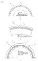
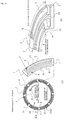
- FIG. 1 illustrates a sliding surface 2 of a sliding component 1 according to Embodiment 1 of the present invention, wherein (a) is a plan view of the sliding surface 2 and (b) is a perspective view showing an enlargement of part of the sliding surface 2.
- the sliding component 1 is an annular body, wherein usually a high-pressure sealed fluid is present on either the internal or external periphery of the sliding surface 2 of the sliding component 1, and the other periphery is exposed to the atmosphere.
- This sealed fluid can be effectively sealed using the sliding component 1.
- the sliding component 1 is used in both a rotation sealing ring and a fixing sealing ring constituting a pair in a mechanical sealing device, for example. The sliding surface of the rotation sealing ring and the sliding surface of the opposing fixing sealing ring are brought in close contact, and a sealed fluid present on either the internal or external periphery of the sliding surface is sealed.
- the sliding component can also be used for a bearing that slides against a rotating shaft while lubricating oil is sealed in one side in the axial direction of a cylindrical sliding surface.
- FIG. 1 for the sake of convenience in the description, a case is described in which the high-pressure sealed fluid is present on the external periphery.
- a counterpart sliding component rotates in a counterclockwise direction relative to the annular body sliding component 1. This holds true even if the sliding component 1 rotates in a clockwise direction.
- the external periphery is provided with a positive pressure generating mechanism 3 composed of a Rayleigh step mechanism, a modified Rayleigh step mechanism, a spiral groove, a dimple, or another positive pressure generating groove; and the internal periphery is provided with a negative pressure generating mechanism 4 composed of a reverse Rayleigh step mechanism, a modified reverse Rayleigh step mechanism, a reverse spiral groove, or another negative pressure generating groove.
- the positive pressure generating mechanism 3 which is composed of a Rayleigh step mechanism, a modified Rayleigh step mechanism, a spiral groove, a dimple, or another positive pressure generating groove
- the negative pressure generating mechanism 4 which is composed of a reverse Rayleigh step mechanism, a modified reverse Rayleigh step mechanism, a reverse spiral groove, or another negative pressure generating groove; are described hereinafter.
- a Rayleigh step mechanism is described as an example of the positive pressure generating mechanism 3
- a reverse Rayleigh step mechanism is described as an example of the negative pressure generating mechanism 4.
- a plurality of Rayleigh step mechanisms 3 and reverse Rayleigh step mechanisms 4 are provided in parallel in the circumferential direction so as to constitute pairs and are formed so that as seen from the upstream side, the upstream end of a groove part 5 of an n th Rayleigh step mechanism 3(n) and the downstream end of a groove part 6 of an n-1 tn reverse Rayleigh step mechanism 4(n-1) substantially coincide in a position in the circumferential direction; and these groove parts 5, 6 are communicated with the high-pressure fluid side via a shared radial-direction groove 7 communicated directly with the high-pressure fluid side.
- the groove part 5 of the Rayleigh step mechanism 3 and the groove part 6 of the reverse Rayleigh step mechanism 4 are isolated from the low-pressure fluid side by a seal surface 8 on the internal peripheral side. Specifically, the radial-direction groove 7 is communicated with the high-pressure fluid side but is not communicated with the low-pressure fluid side.
- FIG. 2 is a drawing showing a modification of FIG. 1 , and in FIG. 2 , the same symbols as FIG. 1 indicate the same members as FIG. 1 , and detailed descriptions are omitted.
- the means for communicating the groove parts 5, 6 with the high-pressure fluid side is different from that of FIG. 1 , and a communication means 50 is configured from a radial-direction groove 51 and a communication hole 52 not communicated with the high-pressure fluid side due to the sliding surface 2.
- the radial-direction groove 51 of FIG. 2 is not directly communicated with the high-pressure fluid side as is the radial-direction groove 7 of FIG.
- the radial-direction groove 51 itself is formed so as to not be communicated with the high-pressure fluid side due to the sliding surface 2, and the groove parts 5, 6 are communicated with the high-pressure fluid side by the communication hole 52 joining the radial-direction groove 51 and the high-pressure fluid side.
- the communication hole 52 being curved at a substantially right angle from the radial-direction groove 51 as shown in FIG. 2(b) , is designed so as to be communicated with the high-pressure fluid side positioned on the external peripheral side of the sliding component 1, but is not limited to such; it may be provided facing outward at a slant. In cases in which the high-pressure fluid side is positioned on the internal peripheral side of the sliding component 1, the communication hole could be formed facing inward at a slant.
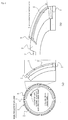
- FIG. 3 is for describing a positive pressure generating mechanism composed of a Rayleigh step mechanism or another positive pressure generating groove and a negative pressure generating mechanism composed of a reverse Rayleigh step mechanism or another negative pressure generating groove, wherein (a) shows a Rayleigh step mechanism, (b) shows a reverse Rayleigh step mechanism, (c) and (e) show modified Rayleigh step mechanisms, and (d) and (f) show modified reverse Rayleigh step mechanisms.
- the sliding component 1 rotatably moves in a clockwise direction
- another sliding component 10 rotatably moves in a counterclockwise direction.
- a Rayleigh step 9 is formed perpendicular to the relative movement directions and facing upstream, and a groove part 5 is formed on the upstream side of the Rayleigh step 9.
- the sliding surface of the other sliding component 10 is flat.
- the sliding component 1 rotatably moves in a clockwise direction and another sliding component 10 rotatably moves in a counterclockwise direction, but in the sliding surface 2 of the sliding component 1, a reverse Rayleigh step 11 is formed perpendicular to the relative movement directions and facing downstream, and a groove part 6 is formed on the downstream side of the reverse Rayleigh step 11.
- the sliding surface of the other sliding component 10 is flat.
- FIG. 3(c) the Rayleigh step 9 of FIG. 3(a) has been altered in shape to a linear inclined surface 9-1
- FIG. 3(e) the Rayleigh step 9 of FIG. 3(a) has been altered in shape to a curved inclined surface 9-2.
- FIGS. 3(c) and (e) substantially the same positive pressure as FIG. 3(a) is generated.
- the configurations of FIGS. 3(c) and (e) are referred to as modified Rayleigh step mechanisms.
- FIG. 3(d) the reverse Rayleigh step 11 of FIG. 3(b) is altered in shape to a linear inclined surface 11-1
- FIG. 3(f) the reverse Rayleigh step 11 of FIG.
- FIGS. 3(b) is altered in shape to a curved inclined surface 11-2. With the configurations of FIGS. 3(d) and (f) , substantially the same negative pressure as FIG. 3(b) is generated. In the present invention, the configurations of FIGS. 3(d) and (f) are referred to as reverse modified Rayleigh step mechanisms.
- FIG. 4 is for describing a positive pressure generating mechanism comprising a spiral groove, a positive pressure generating mechanism composed of a dimple, and a negative pressure generating mechanism composed of a reverse spiral groove, wherein (a) shows the case of a spiral groove, (b) shows the case of a dimple, and (c) shows the case of a reverse spiral groove.
- the positive pressure generating mechanism of FIG. 4(a) a spiral groove 12, is provided over the entire periphery of the sliding surface on the high-pressure side of the sliding component 1 so as to be directly communicated with the high-pressure fluid side.
- the spiral groove 12 generates positive pressure by relative rotational motion with the counterpart sliding surface.
- a dimple 13 is provided over the entire periphery of the sliding surface on the high-pressure side of the sliding component 1 without being directly communicated with the high-pressure fluid side.
- the dimple 13 generates positive pressure by relative rotational motion with the counterpart sliding surface.
- the negative pressure generating mechanism of FIG. 4(c) a reverse spiral groove 14, is provided over the entire periphery of the sliding surface of the sliding component 1 without being directly communicated with the low-pressure fluid side.
- the high-pressure side end of the reverse spiral groove 14 is communicated with a pressure release groove 15, and part of the pressure release groove 15 is connected to the high-pressure fluid side via the radial-direction groove 7.
- the reverse spiral groove 14 is not directly communicated with the low-pressure fluid side, but is isolated by a seal surface. By the relative rotational motion with the counterpart sliding surface, the reverse spiral groove 14 acts to generate negative pressure and draw in fluid leaking from the high-pressure-side fluid, and to push the fluid back to the high-pressure fluid side through the pressure release groove connected to the high-pressure fluid side.
- the sliding surface 2 of the sliding component 1 shown in FIGS. 1 and 2 eight Rayleigh step mechanisms 3 and reverse Rayleigh step mechanisms 4 are provided in parallel in the circumferential direction so as to constitute pairs.
- the depths and widths of the groove parts 5, 6 and the radial-direction grooves 7, 51, the diameter of the communication hole 52, and the width of an internal peripheral seal surface 8 are properties that are suitably determined according to the diameter of the sliding component 1, the sliding surface width, the relative movement rate, the conditions of sealing and lubrication, and other factors.
- the widths of the groove parts 5 and 6 are 0.4 to 0.6 mm, the depths are several microns, the width of the internal peripheral seal surface 8 is 0.2 to 0.4 mm, the width of the radial-direction groove 7 (the angle in the circumferential direction) is approximately 6°, and the depth is several dozen microns.
- FIG. 5 shows the results of a numerical analysis of pressure distribution in the sliding surface of the sliding component according to Embodiment 1, wherein (a) is a partial perspective view of the sliding surface and (b) is a pressure distribution drawing.
- FIG. 5(b) positive pressure is generated in the sliding surface 2, but since the reverse Rayleigh step mechanism 4 is provided in the internal peripheral side, cavitation occurs as a result of negative pressure being generated by the reverse Rayleigh step mechanism 4. Since the cavitation internal pressure is a negative pressure lower than atmospheric pressure, the pressure gradient ⁇ p/ ⁇ r is negative in the low-pressure-side end, the fluid moves from the high-pressure side to the low-pressure side, and as a result, drawing in (pumping) occurs in the internal peripheral side of the sliding surface.
- the pressure in the reverse Rayleigh step mechanism 4 is lower than the low-pressure-side fluid pressure (atmospheric pressure).
- the fluid flows from the constant-pressure fluid side into the reverse Rayleigh step mechanism 4 via the low-pressure-side seal surface 8, and as a result of this, drawing in (pumping) occurs in the internal peripheral side of the sliding surface.
- FIG. 6 is for describing the sliding surface of the comparative example, wherein (a) is a plan view of the sliding surface and (b) is a perspective view showing an enlargement of part of the sliding surface.
- a Rayleigh step mechanism 3 is provided to the external peripheral side of the sliding surface. Through relative movement with a counterpart sliding surface, dynamic pressure (positive pressure) is generated by the Rayleigh step mechanism 3.
- FIG. 7 shows the results of a numerical analysis of pressure distribution in the sliding component of the comparative example, wherein (a) is a partial perspective view of the sliding surface and (b) is a pressure distribution drawing.
- positive pressure is generated in the sliding surface by the Rayleigh step 9, and the fluid pressure in the sliding surface is higher than in the low-pressure fluid side.
- the pressure gradient ⁇ p/ ⁇ r is positive and the fluid moves from the high-pressure side of the sliding surface to the low-pressure side; therefore, as a result, leakage occurs from the high-pressure fluid side to the low-pressure fluid side.
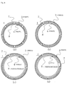
- FIG. 8 shows various examples of the numbers and combinations of Rayleigh step mechanisms 3 as positive pressure generating mechanisms and reverse Rayleigh step mechanisms 4 as negative pressure generating mechanisms in Embodiment 1 of the present invention.
- FIG. 8(a) there are eight Rayleigh step mechanisms 3 and eight reverse Rayleigh step mechanisms 4, and in FIG. 8(b) , there are three Rayleigh step mechanisms 3 and three reverse Rayleigh step mechanisms 4.
- FIG. 8(c) there are three Rayleigh step mechanisms 3 and three reverse Rayleigh step mechanisms 4 and the width w of the internal-peripheral-side seal surface 8 is doubled
- FIG. 8(d) there are three Rayleigh step mechanisms 3 and one reverse Rayleigh step mechanism 4 and the width w of the internal-peripheral-side seal surface 8 is doubled.
- FIG. 9 shows examples of combinations of the spiral groove 12 as a positive pressure generating mechanism and a reverse Rayleigh step mechanism 4 as a negative pressure generating mechanism according to Embodiment 1 of the present invention.
- the spiral groove 12 is provided over the entire periphery, excluding the portion of the radial-direction groove 7, of the high-pressure side of the external peripheral side and is directly communicated with the high-pressure fluid, and one reverse Rayleigh step mechanism 4 is provided to the low-pressure side of the internal peripheral side.
- FIG. 9(a) the spiral groove 12 is provided over the entire periphery, excluding the portion of the radial-direction groove 7, of the high-pressure side of the external peripheral side and is directly communicated with the high-pressure fluid, and one reverse Rayleigh step mechanism 4 is provided to the low-pressure side of the internal peripheral side.
- the spiral groove 12 is provided over the entire periphery, excluding the portion of the radial-direction groove 7, of the high-pressure side of the external peripheral side and is directly communicated with the high-pressure fluid, and four reverse Rayleigh step mechanisms 4 are provided to the low-pressure side of the internal peripheral side.
- FIG. 10 shows an example in which a plurality of reverse Rayleigh step mechanisms are provided in the radial direction in a combination of Rayleigh step mechanisms as positive pressure generating mechanisms and reverse Rayleigh step mechanisms as negative pressure generating mechanisms according to Embodiment 1 of the present invention.
- positive pressure generating mechanisms 3 composed of Rayleigh step mechanisms or other positive pressure generating grooves are provided in the external peripheral side
- negative pressure generating mechanisms 4 composed of reverse Rayleigh step mechanisms or other negative pressure generating grooves are provided in the internal peripheral side.
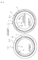
- FIG. 11 shows an example in which a positive pressure generating mechanism is provided to one sliding surface, and a negative pressure generating mechanism is provided to another sliding surface, in Embodiment 1 of the present invention.
- a Rayleigh step mechanism 3 as a positive pressure generating mechanism is provided to the sliding surface 2-1 of one sliding component 1-1
- a reverse Rayleigh step mechanism 4 as a negative pressure generating mechanism is provided to the sliding surface 2-2 of another sliding component 1-2.
- the Rayleigh step mechanism 3 as a positive pressure generating mechanism and the reverse Rayleigh step mechanism 4 as a negative pressure generating mechanism are provided to separate sliding surfaces, there is no leakage when no motion is occurring, the pressure gradient ⁇ p/ ⁇ r of the low-pressure-side ends of the sliding surfaces can always be made negative including at the start of relative sliding, a pumping action occurs from the low-pressure side of the sliding surface toward the high-pressure fluid side, and the effect of significantly reducing the leakage rate can be achieved, similar to cases in which the Rayleigh step mechanism 3 as a positive pressure generating mechanism and the reverse Rayleigh step mechanism 4 as a negative pressure generating mechanism are provided to the same sliding surface.
- the mechanisms are more easily disposed in the sliding surfaces, and the machining timing can be shortened.
- the external peripheral sides of the pair of sliding components are the high-pressure fluid sides and the internal peripheral sides are the low-pressure fluid sides
- the fluid used in lubrication is less susceptible to the effects of centrifugal force from rotation, an appropriate amount of fluid can be ensured between the sliding surfaces, and a better state of fluid lubrication can therefore be achieved.
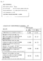
- FIG. 12 is a chart showing the relationship between pressure and leakage rate in the examples (a) through (d) in the embodiment of the present invention shown in FIG. 8 and in the comparative example shown in FIG. 6 .
- the leakage rate of the comparative example was by far the highest, and the leakage rates of the examples (a) through (d) in the embodiment shown in FIG. 8 was low, from which it is clear that a reverse Rayleigh step mechanism contributes to reducing the leakage rate.
- the leakage rate was the lowest in the case of example (d), in which there were three Rayleigh step mechanisms and one reverse Rayleigh step mechanism, and the width w of the seal surface on the internal peripheral side was doubled.
- FIG. 13 is for describing the sliding surface 2 of the sliding component 1 according to Embodiment 2 of the present invention, wherein (a) is a plan view of the sliding surface 2 and (b) is a perspective view showing an enlargement of part of the sliding surface 2.
- the same symbols as those of Embodiment 1 indicate the same members as Embodiment 1, and detailed descriptions are omitted.
- the rotational direction of the counterpart sliding component opposing the annular sliding component 1 is a counterclockwise direction. This is the same even if the sliding component 1 rotates in a clockwise direction.
- the external peripheral side of the sliding surface 2 of the sliding component 1 is provided with a positive pressure generating groove 3 composed of a Rayleigh step mechanism, a modified Rayleigh step mechanism, a spiral groove, a dimple, or the like; and the internal peripheral side is provided with a negative pressure generating mechanism 4 composed of a reverse Rayleigh step mechanism, a modified reverse Rayleigh step mechanism, a reverse spiral groove, or the like.
- a positive pressure generating groove 3 composed of a Rayleigh step mechanism, a modified Rayleigh step mechanism, a spiral groove, a dimple, or the like
- a negative pressure generating mechanism 4 composed of a reverse Rayleigh step mechanism, a modified reverse Rayleigh step mechanism, a reverse spiral groove, or the like.
- FIG. 13 uses a Rayleigh step mechanism as an example of a positive pressure generating mechanism 3, and a reverse Rayleigh step mechanism as an example of a negative pressure generating mechanism 4.
- a pressure release groove 15 is provided between the Rayleigh step mechanism 3 and the reverse Rayleigh step mechanism 4.
- the pressure release groove 15 is for releasing the dynamic pressure (positive pressure) generated in the high-pressure-side positive pressure generating mechanism, e.g., the Rayleigh step mechanism 3 to the pressure of the high-pressure fluid, and thereby preventing fluid from flowing into the low-pressure-side negative pressure generating mechanism, e.g., the reverse Rayleigh step mechanism 4 and weakening the negative-pressure-generating capability of the negative pressure generating mechanism. Fluid attempting to flow to the low-pressure fluid side due to the pressure generated in the high-pressure-side positive pressure generating mechanism is led to the pressure release groove 15, which fulfills the role of letting the fluid into the high-pressure fluid side.
- the pressure release groove 15 is formed from a circular groove, and is disposed between the Rayleigh step mechanism 3 and the reverse Rayleigh step mechanism 4 and separated from the two mechanisms by predetermined sliding surface widths.
- the depth of the circular groove is approximately the same depth as the radial-direction groove 7 and the width is sufficient to release high pressures, for example, and part of the groove is connected to the high-pressure fluid side.
- the Rayleigh step mechanism 3, the reverse Rayleigh step mechanism 4, and the pressure release groove 15 are communicated with the high-pressure fluid side via the radial-direction groove 7, and are separated from the low-pressure fluid side by the seal surface 8.
- the radial-direction groove 7 communicates the Rayleigh step mechanism 3, the reverse Rayleigh step mechanism 4, and the pressure release groove 15 with the high-pressure fluid side but prevents their being communicated with the low-pressure fluid side.
- a plurality of Rayleigh step mechanisms 3 and reverse Rayleigh step mechanisms 4 are provided on either side of the pressure release groove 15 so as to be parallel in the circumferential direction and constitute pairs.
- the upstream end of the groove part 5 of the n th Rayleigh step mechanism 3 (n) and the downstream end of the groove part 6 of the n-1 tn reverse Rayleigh step mechanism 4 (n-1) are formed so as to substantially coincide in a position in the circumferential direction, and the groove parts 5, 6 and the pressure release groove 15 are communicated with the high-pressure fluid side via the shared radial-direction groove 7.
- FIG. 14 is a drawing showing a modification of FIG. 13 , symbols in FIG. 14 that are the same as FIG. 13 indicate the same symbols as FIG. 13 , and detailed descriptions are omitted.
- the means for communicating the groove parts 5, 6 with the high-pressure fluid side is different from that of FIG. 13 , and the communication means 50 is configured from the radial-direction groove 51 and the communication hole 52 not communicated with high-pressure fluid side by the sliding surface 2.
- the radial-direction groove 51 of FIG. 14 is not directly communicated with the high-pressure fluid side as is the radial-direction groove 7 of FIG.
- the radial-direction groove 51 itself is formed so as to not be communicated with high-pressure fluid side by the sliding surface 2, and the groove parts 5, 6 are communicated with high-pressure fluid side by the communication hole 52 that joins the radial-direction groove 51 and the high-pressure fluid side.
- the communication hole 52 being curved at a substantially right angle from the radial-direction groove 51 as shown in FIG. 14(b) , is designed so as to be communicated with the high-pressure fluid side positioned on the external peripheral side of the sliding component 1, but is not limited to such and may be provided facing outward at a slant. In cases in which the high-pressure fluid side is positioned on the internal peripheral side of the sliding component 1, the communication hole could be formed facing inward at a slant.
- FIG. 15 shows various examples of combinations of Rayleigh step mechanisms 3 and spiral grooves 12 as positive pressure generating mechanisms, and reverse Rayleigh step mechanisms 4 and reverse spiral grooves 14 as negative pressure generating mechanisms, according to Embodiment 2 of the present invention.
- the rotational direction of the counterpart sliding surface is the same counterclockwise direction as FIG. 13 .
- FIG. 15(b) there are eight Rayleigh step mechanisms 3 disposed on the external peripheral high-pressure side of the sliding component 1 and eight reverse Rayleigh step mechanisms 4 disposed on the internal peripheral low-pressure side, between which the pressure release groove 15 is disposed.
- FIG. 15(c) there are eight Rayleigh step mechanisms 3 disposed on the external peripheral high-pressure side of the sliding component 1 and a reverse spiral groove 14 provided around the entire periphery of the internal peripheral low-pressure side, between which the pressure release groove 15 is disposed.
- a spiral groove 12 is provided around the entire periphery of the external peripheral high-pressure side of the sliding component 1 and one reverse Rayleigh step mechanism 4 is disposed on the internal peripheral low-pressure side, between which the pressure release groove 15 is disposed.
- a spiral groove 12 is provided around the entire periphery of the external peripheral high-pressure side of the sliding component 1 and eight reverse Rayleigh step mechanisms 4 are disposed on the internal peripheral low-pressure side, between which the pressure release groove 15 is disposed.
- a spiral groove 12 is provided around the entire periphery of the external peripheral high-pressure side of the sliding component 1 and a reverse spiral groove 14 is provided around the entire periphery of the internal peripheral low-pressure side, between which the pressure release groove 15 is disposed.
- the pressure release groove 15 fulfills the role of releasing pressure to the high-pressure fluid side of the reverse spiral groove 14.
- the leakage rate is low in (a) and (d) in which the number of reverse Rayleigh step mechanisms 4 is low.
- FIG. 16 shows an example in Embodiment 2 of the present invention, in which a positive pressure generating mechanism is provided to one sliding surface and a negative pressure generating mechanism is provided to another sliding surface.
- a Rayleigh step mechanism 3 as a positive pressure generating mechanism is provided to the sliding surface 2-1 of one sliding component 1-1
- a reverse Rayleigh step mechanism 4 as a negative pressure generating mechanism is provided to the sliding surface 2-2 of the other sliding component 1-2.
- the mechanisms are more easily disposed in the sliding surfaces, and the machining timing can be shortened.
- the external peripheral sides of the pair of sliding components are the high-pressure fluid sides and the internal peripheral sides are the low-pressure fluid sides
- the fluid used in lubrication is less susceptible to the effects of centrifugal force from rotation, an appropriate amount of fluid can be ensured between the sliding surfaces, and a better state of fluid lubrication can therefore be achieved.
- FIG. 17 shows an example in Embodiment 2 of the present invention, in which a plurality of reverse Rayleigh step mechanisms as a negative pressure generating mechanism are provided in the radial direction.
- the external peripheral side is provided with positive pressure generating mechanisms 3 composed of Rayleigh step mechanisms or other positive pressure generating grooves
- the internal peripheral side is provided with negative pressure generating mechanisms 4 composed of reverse Rayleigh step mechanisms or other negative pressure generating grooves.
- a pressure release groove 15 is provided between the Rayleigh step mechanisms 3 and the reverse Rayleigh step mechanisms 4.
- the pressure release groove 15 is for releasing the dynamic pressure (positive pressure) generated in the high-pressure-side positive pressure generating mechanisms, e.g., the Rayleigh step mechanisms 3 to the pressure of the high-pressure fluid, and thereby preventing fluid from flowing into the low-pressure-side negative pressure generating mechanisms, e.g., the reverse Rayleigh step mechanisms 4 and weakening the negative-pressure-generating capability of the negative pressure generating mechanisms. Fluid attempting to flow to the low-pressure fluid side due to the pressure generated in the high-pressure-side positive pressure generating mechanisms is led to the pressure release groove 15, which fulfills the role of letting the fluid into the high-pressure fluid side.
- the pressure release groove 15 fulfills the role of letting the fluid into the high-pressure fluid side.
- FIG. 18 shows a modification of FIG. 17 , wherein a pressure release groove is provided between a plurality of reverse Rayleigh step mechanisms.
- the external peripheral side is provided with positive pressure generating mechanisms 3 composed of Rayleigh step mechanisms or other positive pressure generating grooves
- the internal peripheral side is provided with negative pressure generating mechanisms 4 composed of reverse Rayleigh step mechanisms or other negative pressure generating grooves.
- Respective pressure release grooves 15 are provided between the Rayleigh step mechanisms 3 and the radially external reverse Rayleigh step mechanisms 4-1, between the radially external reverse Rayleigh step mechanisms 4-1 and the radially intermediate reverse Rayleigh step mechanisms 4-2, and between the radially intermediate reverse Rayleigh step mechanisms 4-2 and the radially internal reverse Rayleigh step mechanisms 4-3.
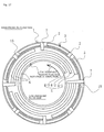
- FIG. 19 shows an example in Embodiment 2 of the present invention in which Rayleigh step mechanisms as positive pressure generating mechanisms and reverse Rayleigh step mechanisms as negative pressure generating mechanisms are staggered in the circumferential direction.
- positive pressure generating mechanisms 3 composed of Rayleigh step mechanisms or the like are provided in the external peripheral side
- negative pressure generating mechanisms 4 composed of reverse Rayleigh step mechanisms or the like are provided in the internal peripheral side.
- FIG. 19 shows a configuration in which there are eight external peripheral Rayleigh step mechanisms 3 and four internal peripheral reverse Rayleigh step mechanisms 4, and four radial-direction grooves 53 communicated with the reverse Rayleigh step mechanisms 4 are provided in positions that are circumferentially midway between each of the eight radial-direction grooves 7 communicated with the Rayleigh step mechanisms 3; wherein the Rayleigh step mechanisms 3 as positive pressure generating mechanisms and the reverse Rayleigh step mechanisms 4 as negative pressure generating mechanisms are staggered in the circumferential direction.
- Pressure release grooves 15 are also provided between the Rayleigh step mechanisms 3 and the reverse Rayleigh step mechanisms 4, and the four radial-direction grooves 53 are communicated with the eight radial-direction grooves 7 via the pressure release grooves 15.
- the radial-direction grooves 53 are disposed in the internal peripheral side and are not communicated directly with the high-pressure fluid side, but are communicated with the high-pressure fluid side via the pressure release grooves 15 and the radial-direction grooves 7.
- the radial-direction grooves 53 communicated with the reverse Rayleigh step mechanisms 4 are not communicated directly with the high-pressure fluid side but are communicated with the high-pressure fluid side via the narrow pressure release grooves 15, the pressure of the radial-direction grooves 53 decreases and leakage from the radial-direction grooves 53 to the static-pressure fluid side is reduced.
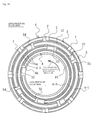
- FIG. 20 shows an example in FIG. 19 in which a plurality of reverse Rayleigh step mechanisms as negative pressure generating mechanisms are provided in the radial direction.
- positive pressure generating mechanisms 3 composed of Rayleigh step mechanisms or other positive pressure generating grooves are provided in the external peripheral side
- negative pressure generating mechanisms 4 composed of reverse Rayleigh step mechanisms or other negative pressure generating grooves are provided in the internal peripheral side.
- peripheral Rayleigh step mechanisms 3 there are eight external peripheral Rayleigh step mechanisms 3, three rows of internal peripheral reverse Rayleigh step mechanisms 4 are provided in the radial direction, four radially outer reverse Rayleigh step mechanisms 4-1 are provided, two radially intermediate reverse Rayleigh step mechanisms 4-2 are provided, and one radially inner reverse Rayleigh step mechanism 4-3 is provided.
- Respective pressure release grooves 15 are provided between the Rayleigh step mechanisms 3 and the radially outer reverse Rayleigh step mechanisms 4-1, between the radially outer reverse Rayleigh step mechanisms 4-1 and the radially intermediate reverse Rayleigh step mechanisms 4-2, and between the radially intermediate reverse Rayleigh step mechanisms 4-2 and the radially inner reverse Rayleigh step mechanism 4-3.
- the eight external peripheral Rayleigh step mechanisms 3 are respectively communicated with the eight radial-direction grooves 7 directly communicated with the high-pressure fluid side, the four radially outer reverse Rayleigh step mechanisms 4-1 are respectively communicated with four radial-direction grooves 54 provided in the same circumferential formation, the two radially intermediate reverse Rayleigh step mechanisms 4-2 are respectively communicated with two radial-direction grooves 55 provided in the same circumferential formation, the one radially inner reverse Rayleigh step mechanism 4-3 is communicated with one radial-direction groove 56 provided in the same circumferential formation, and the radial-direction grooves 7, 54, 55, 56 of each row are disposed so that their positions are staggered in the circumferential direction.
- the four radially outer reverse Rayleigh step mechanisms 4-1 are communicated with the high-pressure fluid side via the four radial-direction grooves 54 provided in the same circumferential formation, the pressure release groove 15, and the radial-direction grooves 7;
- the two radially intermediate reverse Rayleigh step mechanisms 4-2 are communicated with the high-pressure fluid side via the two radial-direction grooves 55 provided in the same circumferential formation, the pressure release groove 15, the radial-direction grooves 54, and the radial-direction grooves 7;
- the one radially inner reverse Rayleigh step mechanism 4-3 is communicated with the high-pressure fluid side via the one radial-direction groove 56 provided in the same circumferential formation, the pressure release groove 15, the radial-direction grooves 55, 54, and the radial-direction grooves 7.
- the radial-direction grooves 7, 54, 55, 56 are provided in each row and the radial-direction grooves 7, 54, 55, 56 of each row are disposed so as to be staggered in the circumferential direction, the high-pressure fluid is not directly communicated with the internal peripheral side vicinity of the sliding surface via the radial-direction grooves, and leakage from the high-pressure fluid side to the low-pressure fluid side can therefore be better prevented.
- FIG. 21 is for describing the sliding surface 2 of the sliding component 1 according to Embodiment 3 of the present invention, wherein (a) is a plan view of the sliding surface 2 and (b) is a perspective view showing an enlargement of part of the sliding surface 2.
- the same symbols as those of Embodiments 1 and 2 indicate the same members as Embodiments 1 and 2, and detailed descriptions are omitted.
- the rotational direction of the counterpart sliding component opposing the annular sliding component 1 is a counterclockwise direction. This is the same even if the sliding component 1 rotates in a clockwise direction.
- Embodiment 1 the concept that the smaller the number of reverse Rayleigh step mechanisms 4 (the smaller the number of radial-direction grooves 7) and the greater the width w of the internal-peripheral-side seal surface 8, the lower the leakage rate, is as described in Embodiment 1 and so forth. Needless to say, however, the number of radial-direction grooves 7 cannot be zero, and there is a certain limit on the width w of the internal-peripheral-side seal surface 8.
- the grooves 7 are slanted in the rotational direction of the counterpart sliding surface and are disposed in a direction of expanding in a radial formation in the rotational direction of the counterpart sliding surface, as shown in FIG. 21 .
- the radial-direction groove 7 is shaped so as to be slanted in the rotational direction of the counterpart sliding surface from the internal peripheral side toward the external peripheral side, and when a plurality of radial-direction grooves 7 are disposed in the circumferential direction, the grooves are disposed in a direction of expanding in a radial formation in the rotational direction of the counterpart sliding surface.
- the groove is shaped so as to be slanted in the rotational direction of the counterpart sliding surface from the internal peripheral side communicated with the groove parts 6 of the reverse Rayleigh step mechanisms 4 toward the pressure release groove 15 positioned in the external peripheral side, and in the portions of the Rayleigh step mechanisms 3 positioned in the outermost peripheral side of the radial direction, the groove is shaped facing in a direction 90° relative to the circumferential direction (the tangential direction). Therefore, fluid that flows from the groove parts 6 of the reverse Rayleigh step mechanisms 4 into the radial-direction groove 7 is expelled in the direction shown by the arrow 16.
- the radial-direction groove 7 may be shaped so as to be uniformly slanted in the rotational direction of the counterpart sliding surface from the internal peripheral side communicated with the groove parts 6 of the reverse Rayleigh step mechanisms 4 up to the external-peripheral-side ends, but essentially the groove is preferably shaped so as to be slanted in the rotational direction of the counterpart sliding surface from the internal peripheral side toward the external peripheral side.
- the width of the radial-direction groove 7 may be shaped so as to gradually expand from the internal peripheral side toward the external peripheral side.
- the internal peripheral side of the radial-direction groove 7 is closed off by the seal surface 8; therefore, the same negative pressure effect as with a reverse spiral groove occurs in the radial-direction groove 7, fluid leaking from the high-pressure side is drawn in, creating an action of pushing back to the high-pressure fluid side in a state of a lessened positive pressure gradient in the radial direction, and leakage from the radial-direction groove 7 is therefore reduced.
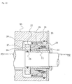
- FIG. 22 is a cross-sectional view of a mechanical seal on which is mounted another sliding component paired with the sliding component of the present invention.
- the sliding component 1 of the present invention is mounted as a fixing sealing ring 21.
- the fixing sealing ring 21 is movably mounted via an O ring 24 in a holding ring 23 secured to a housing 30.
- the fixing sealing ring 21 creates a seal between an internal side P2 and an atmosphere side P1 while a sliding surface 22 is pressed and held firmly against the opposing sliding surface 29 by a spring 25.
- the external peripheral side is provided with a positive pressure generating mechanism 27 composed of a Rayleigh step mechanism, a modified Rayleigh step mechanism, a spiral groove, a dimple, or the like; and the internal peripheral side of the sliding surface 22 is provided with a negative pressure generating mechanism 28 composed of a reverse Rayleigh step mechanism, a modified reverse Rayleigh step mechanism, a reverse spiral groove, or the like.
- FIG. 23 is a cross-sectional view of a thrust bearing on which is mounted another sliding component paired with the sliding component of the present invention.
- the number 40 indicates an entire thrust bearing, which is basically configured from a cylindrical housing 44 which is disposed so as to enclose the external peripheral surface of an annular ridged protrusion 42 provided to a rotating shaft 41, and which has an internal peripheral surface that faces the external periphery of the ridged protrusion 42 via a minuscule radial-direction gap 43; and thrust receivers 46, 47 which extend inward in the radial direction from both ends of the housing 44 and which face the end surfaces of the ridged protrusion 42 via tiny gaps 45 in the thrust direction; the bearing body being configured by the housing 44 and the thrust receivers 46, 47.
- the thrust receivers 46, 47 of the bearing body and the end surfaces of the ridged protrusion 42 are in rotatable slidable contact with each other in the axial direction.
- a lubricant is held by its own surface tension in the minuscule radial-direction gap 43 and the minuscule thrust-direction gaps 45.
- the external peripheral sides of the sliding surfaces of the thrust receivers 46, 47 are provided with positive pressure generating mechanisms 48 composed of Rayleigh step mechanisms, modified Rayleigh step mechanisms, spiral grooves, dimples, or the like, and the internal peripheral sides of the sliding surfaces are provided with negative pressure generating mechanisms 49 composed of reverse Rayleigh step mechanisms, modified reverse Rayleigh step mechanisms, reverse spiral grooves, or the like.
Landscapes
- Engineering & Computer Science (AREA)
- General Engineering & Computer Science (AREA)
- Mechanical Engineering (AREA)
- Physics & Mathematics (AREA)
- Fluid Mechanics (AREA)
- Mechanical Sealing (AREA)
- Sliding-Contact Bearings (AREA)
- Sealing Devices (AREA)
Priority Applications (1)
| Application Number | Priority Date | Filing Date | Title |
|---|---|---|---|
| EP17196376.2A EP3321548B1 (fr) | 2010-10-06 | 2011-10-05 | Pièce coulissante |
Applications Claiming Priority (2)
| Application Number | Priority Date | Filing Date | Title |
|---|---|---|---|
| JP2010226949 | 2010-10-06 | ||
| PCT/JP2011/072921 WO2012046749A1 (fr) | 2010-10-06 | 2011-10-05 | Partie glissante |
Related Child Applications (2)
| Application Number | Title | Priority Date | Filing Date |
|---|---|---|---|
| EP17196376.2A Division EP3321548B1 (fr) | 2010-10-06 | 2011-10-05 | Pièce coulissante |
| EP17196376.2A Division-Into EP3321548B1 (fr) | 2010-10-06 | 2011-10-05 | Pièce coulissante |
Publications (3)
| Publication Number | Publication Date |
|---|---|
| EP2626604A1 true EP2626604A1 (fr) | 2013-08-14 |
| EP2626604A4 EP2626604A4 (fr) | 2017-03-08 |
| EP2626604B1 EP2626604B1 (fr) | 2019-06-12 |
Family
ID=45927744
Family Applications (2)
| Application Number | Title | Priority Date | Filing Date |
|---|---|---|---|
| EP17196376.2A Active EP3321548B1 (fr) | 2010-10-06 | 2011-10-05 | Pièce coulissante |
| EP11830681.0A Active EP2626604B1 (fr) | 2010-10-06 | 2011-10-05 | Partie glissante |
Family Applications Before (1)
| Application Number | Title | Priority Date | Filing Date |
|---|---|---|---|
| EP17196376.2A Active EP3321548B1 (fr) | 2010-10-06 | 2011-10-05 | Pièce coulissante |
Country Status (5)
| Country | Link |
|---|---|
| US (5) | US8814433B2 (fr) |
| EP (2) | EP3321548B1 (fr) |
| JP (1) | JP5693599B2 (fr) |
| CN (1) | CN103097782B (fr) |
| WO (1) | WO2012046749A1 (fr) |
Cited By (23)
| Publication number | Priority date | Publication date | Assignee | Title |
|---|---|---|---|---|
| EP2902677A4 (fr) * | 2012-09-29 | 2016-05-11 | Eagle Ind Co Ltd | Partie coulissante |
| WO2016090203A1 (fr) * | 2014-12-05 | 2016-06-09 | Energy Recovery Inc. | Caractéristiques de palier hydrodynamique |
| EP2990700A4 (fr) * | 2013-04-24 | 2016-10-12 | Eagle Ind Co Ltd | Pièce coulissante |
| EP3091258A4 (fr) * | 2013-12-09 | 2017-10-04 | Eagle Industry Co., Ltd. | Élément de coulissement |
| US9951873B2 (en) | 2013-01-16 | 2018-04-24 | Eagle Industry Co., Ltd. | Sliding component |
| EP3190317A4 (fr) * | 2014-09-04 | 2018-05-02 | Eagle Industry Co., Ltd. | Joint d'étanchéité mécanique |
| FR3061750A1 (fr) * | 2017-01-10 | 2018-07-13 | Renault S.A.S | Butee fixe d'un systeme de butees fixe et tournante destine a supporter une charge axiale. |
| EP3309431A4 (fr) * | 2015-06-15 | 2019-02-27 | Eagle Industry Co., Ltd. | Pièce de glissement |
| KR20190053947A (ko) * | 2016-11-14 | 2019-05-20 | 이구루코교 가부시기가이샤 | 슬라이딩 부품 |
| KR20190064639A (ko) * | 2016-11-16 | 2019-06-10 | 이구루코교 가부시기가이샤 | 슬라이딩 부품 |
| EP3361128A4 (fr) * | 2015-10-05 | 2019-06-12 | Eagle Industry Co., Ltd. | Élément coulissant |
| CN110594418A (zh) * | 2019-10-10 | 2019-12-20 | 大连因联科技有限公司 | 一种雷列台阶浅槽的机械密封端面结构 |
| CN111997999A (zh) * | 2020-08-20 | 2020-11-27 | 浙江申发轴瓦股份有限公司 | 一种可倾瓦滑动轴承轴瓦结构和可倾瓦滑动轴承 |
| EP3677802A4 (fr) * | 2017-08-28 | 2021-05-26 | Eagle Industry Co., Ltd. | Pièce de glissement |
| KR20210090703A (ko) * | 2018-12-21 | 2021-07-20 | 이구루코교 가부시기가이샤 | 슬라이딩 부품 |
| US11608897B2 (en) | 2018-08-01 | 2023-03-21 | Eagle Industry Co., Ltd. | Slide component |
| US11815184B2 (en) | 2018-11-30 | 2023-11-14 | Eagle Industry Co., Ltd. | Sliding component |
| US11821462B2 (en) | 2018-08-24 | 2023-11-21 | Eagle Industry Co., Ltd. | Sliding member |
| US11892081B2 (en) | 2019-07-26 | 2024-02-06 | Eagle Industry Co., Ltd. | Sliding component |
| US11933405B2 (en) | 2019-02-14 | 2024-03-19 | Eagle Industry Co., Ltd. | Sliding component |
| US12007027B2 (en) | 2019-04-24 | 2024-06-11 | Eagle Industry Co., Ltd. | Sliding component |
| US12013040B2 (en) | 2019-02-21 | 2024-06-18 | Eagle Industry Co., Ltd. | Sliding components |
| US12018757B2 (en) | 2019-02-04 | 2024-06-25 | Eagle Industry Co., Ltd. | Sliding components |
Families Citing this family (79)
| Publication number | Priority date | Publication date | Assignee | Title |
|---|---|---|---|---|
| JP5758378B2 (ja) * | 2010-03-15 | 2015-08-05 | イーグル工業株式会社 | 摺動部材 |
| US9447884B2 (en) * | 2011-09-03 | 2016-09-20 | Eagle Industry Co., Ltd. | Sliding parts |
| EP2853786B1 (fr) * | 2012-05-21 | 2018-07-11 | Eagle Industry Co., Ltd. | Composant coulissant |
| WO2013176009A1 (fr) * | 2012-05-21 | 2013-11-28 | イーグル工業株式会社 | Composant coulissant |
| WO2014024742A1 (fr) * | 2012-08-04 | 2014-02-13 | イーグル工業株式会社 | Composant de coulissement |
| EP2940353B1 (fr) * | 2012-12-25 | 2020-01-15 | Eagle Industry Co., Ltd. | Élément coulissant |
| CN104520616B (zh) * | 2012-12-25 | 2016-08-24 | 伊格尔工业股份有限公司 | 滑动部件 |
| AU2014239820B2 (en) * | 2013-03-17 | 2016-07-21 | Eagle Industry Co., Ltd. | Sliding component |
| WO2014148317A1 (fr) * | 2013-03-17 | 2014-09-25 | イーグル工業株式会社 | Élément glissant |
| EP3051188B1 (fr) * | 2013-09-27 | 2018-08-01 | Eagle Industry Co., Ltd. | Composant coulissant |
| CN105683633B (zh) * | 2013-09-27 | 2019-01-29 | 株式会社理研 | 密封圈 |
| CN105683632B (zh) * | 2013-11-22 | 2017-07-07 | 伊格尔工业股份有限公司 | 滑动部件 |
| US9677670B2 (en) * | 2013-12-09 | 2017-06-13 | Eagle Industry Co., Ltd. | Sliding parts |
| EP3112078B1 (fr) * | 2014-02-24 | 2020-04-15 | Eagle Industry Co., Ltd. | Élément glissant et procédé de traitement d'élément glissant |
| US9765892B2 (en) * | 2014-06-26 | 2017-09-19 | Eagle Industry Co., Ltd. | Sliding component |
| AU2015281105B2 (en) * | 2014-06-26 | 2017-08-31 | Eagle Industry Co., Ltd. | Sliding component |
| WO2016042995A1 (fr) * | 2014-09-20 | 2016-03-24 | イーグル工業株式会社 | Élément coulissant |
| AU2015344384A1 (en) * | 2014-11-08 | 2017-04-27 | Eagle Industry Co., Ltd. | Sliding parts |
| EP3239543B1 (fr) * | 2014-12-22 | 2022-10-05 | Eagle Industry Co., Ltd. | Palier de coulissement et pompe |
| US10487944B2 (en) | 2015-01-31 | 2019-11-26 | Eagle Industry Co., Ltd. | Slide component |
| JP6559717B2 (ja) * | 2015-02-05 | 2019-08-14 | イーグル工業株式会社 | メカニカルシール |
| CN107407417B (zh) * | 2015-03-16 | 2019-11-01 | Nok株式会社 | 密封环 |
| CN107407424B (zh) * | 2015-04-15 | 2019-11-22 | 伊格尔工业股份有限公司 | 滑动部件 |
| JP6311644B2 (ja) * | 2015-04-28 | 2018-04-18 | 株式会社Soken | ギヤポンプ装置 |
| US10598286B2 (en) * | 2015-05-19 | 2020-03-24 | Eagle Industry Co., Ltd. | Slide component |
| WO2016186015A1 (fr) * | 2015-05-20 | 2016-11-24 | イーグル工業株式会社 | Élément de coulissement |
| EP3299686B1 (fr) * | 2015-05-21 | 2022-03-23 | Eagle Industry Co., Ltd. | Élément de coulissement |
| CN107735606B (zh) * | 2015-06-27 | 2020-09-11 | 伊格尔工业股份有限公司 | 滑动部件 |
| CN105114446B (zh) * | 2015-09-15 | 2018-06-26 | 武汉理工大学 | 可变阶梯阻尼推力轴承 |
| US10036474B2 (en) * | 2015-09-23 | 2018-07-31 | Hamilton Sundstrand Corporation | Vented lift off seal assemblies |
| US10415707B2 (en) | 2016-06-30 | 2019-09-17 | General Electric Company | Face seal assembly and an associated method thereof |
| US10626743B2 (en) | 2016-06-30 | 2020-04-21 | General Electric Company | Segmented face seal assembly and an associated method thereof |
| CN106122482B (zh) * | 2016-07-28 | 2018-11-13 | 浙江工业大学 | 一种低泄漏非接触机械密封端面结构 |
| JP6820120B2 (ja) * | 2016-08-15 | 2021-01-27 | イーグル工業株式会社 | 摺動部品 |
| US11739844B2 (en) * | 2016-09-14 | 2023-08-29 | Eagle Industry Co., Ltd. | Mechanical seal |
| CN109906330B (zh) | 2016-10-14 | 2021-12-14 | 伊格尔工业股份有限公司 | 滑动部件 |
| KR102288158B1 (ko) | 2016-11-14 | 2021-08-11 | 이구루코교 가부시기가이샤 | 슬라이딩 부품 |
| CN109983201B (zh) * | 2016-11-22 | 2021-01-12 | 伊格尔工业股份有限公司 | 密封部件 |
| KR102447226B1 (ko) | 2016-12-07 | 2022-09-26 | 이구루코교 가부시기가이샤 | 슬라이딩 부품 |
| WO2019009345A1 (fr) * | 2017-07-07 | 2019-01-10 | イーグル工業株式会社 | Élément coulissant |
| US11221071B2 (en) | 2017-09-05 | 2022-01-11 | Eagle Industry Co., Ltd. | Sliding component |
| EP3693638A4 (fr) | 2017-10-03 | 2021-06-23 | Eagle Industry Co., Ltd. | Élément coulissant |
| US20190186632A1 (en) * | 2017-12-20 | 2019-06-20 | Caterpillar Inc. | Integrated debris barrier on metal face seals |
| EP3739242A4 (fr) | 2018-01-12 | 2021-10-13 | Eagle Industry Co., Ltd. | Élément coulissant |
| WO2019151396A1 (fr) | 2018-02-01 | 2019-08-08 | イーグル工業株式会社 | Pièces coulissantes |
| US11549589B2 (en) | 2018-02-21 | 2023-01-10 | Eagle Industry Co., Ltd. | Mechanical seal |
| JP6914881B2 (ja) * | 2018-03-29 | 2021-08-04 | 株式会社豊田自動織機 | 遠心圧縮機及びメカニカルシール |
| JP6931783B2 (ja) * | 2018-03-29 | 2021-09-08 | 株式会社豊田自動織機 | 遠心圧縮機及びメカニカルシール |
| EP3816490A4 (fr) | 2018-05-17 | 2022-03-02 | Eagle Industry Co., Ltd. | Bague d'étanchéité |
| US11644100B2 (en) | 2018-05-17 | 2023-05-09 | Eagle Industry Co., Ltd. | Seal ring |
| WO2019221228A1 (fr) * | 2018-05-17 | 2019-11-21 | イーグル工業株式会社 | Bague d'étanchéité |
| CN108644387A (zh) * | 2018-06-26 | 2018-10-12 | 昆明理工大学 | 一种螺旋槽和雷利台阶槽组合的干气密封环 |
| JP7334017B2 (ja) | 2018-10-01 | 2023-08-28 | イーグル工業株式会社 | 摺動部材 |
| JP7387238B2 (ja) * | 2018-10-24 | 2023-11-28 | イーグル工業株式会社 | 摺動部材 |
| JP6856613B2 (ja) * | 2018-12-21 | 2021-04-07 | Tpr株式会社 | 組合せスラストワッシャ |
| CN113330224A (zh) | 2019-02-04 | 2021-08-31 | 伊格尔工业股份有限公司 | 滑动部件 |
| EP3922874A4 (fr) | 2019-02-04 | 2022-11-09 | Eagle Industry Co., Ltd. | Élément coulissant |
| CN113439167B (zh) | 2019-02-04 | 2023-06-02 | 伊格尔工业股份有限公司 | 滑动部件 |
| EP4253779A3 (fr) | 2019-02-04 | 2023-11-08 | Eagle Industry Co., Ltd. | Composant glissant et procédé de fabrication de composant glissant |
| CN113348307B (zh) | 2019-02-04 | 2023-11-14 | 伊格尔工业股份有限公司 | 滑动部件 |
| EP3922873B1 (fr) | 2019-02-04 | 2024-06-26 | Eagle Industry Co., Ltd. | Élément coulissant |
| US11767916B2 (en) | 2019-02-14 | 2023-09-26 | Eagle Industry Co., Ltd. | Sliding components |
| CN113412370B (zh) | 2019-02-15 | 2023-03-10 | 伊格尔工业股份有限公司 | 滑动部件 |
| US11255205B2 (en) * | 2019-03-05 | 2022-02-22 | Raytheon Technologies Corporation | Systems and methods for improving start up wear performance of carbon seals |
| WO2020196145A1 (fr) * | 2019-03-22 | 2020-10-01 | イーグル工業株式会社 | Composant coulissant |
| US11353057B2 (en) | 2019-12-03 | 2022-06-07 | Elliott Company | Journal and thrust gas bearing |
| CN115210488A (zh) | 2020-03-09 | 2022-10-18 | 伊格尔工业股份有限公司 | 滑动部件 |
| US20230175587A1 (en) | 2020-03-31 | 2023-06-08 | Eagle Industry Co., Ltd. | Sliding component |
| EP4151870A4 (fr) | 2020-05-11 | 2024-05-29 | Eagle Industry Co., Ltd. | Composant de coulissement |
| KR20230008818A (ko) * | 2020-06-02 | 2023-01-16 | 이구루코교 가부시기가이샤 | 슬라이딩 부품 |
| CN111520479A (zh) * | 2020-06-03 | 2020-08-11 | 兰州理工大学 | 一种超高压零泄漏机械密封端面结构 |
| CN111520477A (zh) * | 2020-06-03 | 2020-08-11 | 兰州理工大学 | 一种似八卦状机械密封端面结构 |
| CN115715352A (zh) * | 2020-07-06 | 2023-02-24 | 伊格尔工业股份有限公司 | 滑动部件 |
| WO2022009766A1 (fr) * | 2020-07-06 | 2022-01-13 | イーグル工業株式会社 | Élément coulissant |
| JPWO2022009771A1 (fr) | 2020-07-06 | 2022-01-13 | ||
| CN111927886B (zh) * | 2020-07-15 | 2021-11-09 | 杭州电子科技大学 | 基于静压气浮轴承的aacmm高精度关节的支承方法 |
| EP4372253A1 (fr) * | 2021-07-13 | 2024-05-22 | Eagle Industry Co., Ltd. | Éléments coulissants |
| WO2024143307A1 (fr) * | 2022-12-26 | 2024-07-04 | イーグル工業株式会社 | Composant coulissant |
| WO2024143304A1 (fr) * | 2022-12-26 | 2024-07-04 | イーグル工業株式会社 | Composants coulissants |
Family Cites Families (50)
| Publication number | Priority date | Publication date | Assignee | Title |
|---|---|---|---|---|
| GB827015A (en) * | 1957-02-04 | 1960-01-27 | Atomic Energy Authority Uk | Improvements in or relating to shaft seals |
| NL143660B (nl) * | 1965-03-27 | 1974-10-15 | Philips Nv | Axiaal leger. |
| CH541738A (de) * | 1971-06-18 | 1973-10-31 | Ludin Ludwig | Hydrodynamisches Lager |
| NL7213192A (fr) * | 1972-09-29 | 1974-04-02 | ||
| DE2504204C3 (de) * | 1975-02-01 | 1981-11-12 | Skf Kugellagerfabriken Gmbh, 8720 Schweinfurt | Selbstdruckerzeugendes Axialgleitlager |
| IL62344A0 (en) | 1981-03-11 | 1981-05-20 | Tech Res & Dev Found Ltd | A zero-leakage non-contacting mechanical face seal for rotary machines |
| US4406466A (en) * | 1982-11-29 | 1983-09-27 | Elliott Turbomachinery Co., Inc. | Gas lift bearing and oil seal |
| US4645414A (en) * | 1985-06-07 | 1987-02-24 | General Motors Corporation | Combined vacuum pump, bearing and seal assembly |
| CH677266A5 (fr) * | 1986-10-28 | 1991-04-30 | Pacific Wietz Gmbh & Co Kg | |
| US4830572A (en) | 1986-11-13 | 1989-05-16 | Oklejas Jr Eli | Idler disk |
| US4808070A (en) * | 1987-08-17 | 1989-02-28 | Fonda Bonardi G | Fluid bearing |
| US5529464A (en) * | 1988-07-12 | 1996-06-25 | Alliedsignal Inc. | Cryogenic turbopump |
| JPH06105105B2 (ja) * | 1989-03-03 | 1994-12-21 | 日本ピラー工業株式会社 | 端面非接触形メカニカルシール |
| JPH0660691B2 (ja) | 1990-04-17 | 1994-08-10 | イーグル工業株式会社 | 両回転式準接触メカニカルシール及びリング摺動面の溝加工方法 |
| JPH0473636A (ja) | 1990-05-18 | 1992-03-09 | Toshiba Lighting & Technol Corp | 投光光源装置 |
| US5071141A (en) | 1990-07-17 | 1991-12-10 | John Crane Inc. | Spiral groove seal arrangement for high vapor-pressure liquids |
| JPH0529247A (ja) | 1991-07-18 | 1993-02-05 | Fujitsu Ltd | 半導体装置の製造方法 |
| DE4303237A1 (de) * | 1992-02-06 | 1993-10-21 | Eagle Ind Co Ltd | Gasdichtung |
| JPH0769019B2 (ja) * | 1992-05-18 | 1995-07-26 | 日本ピラー工業株式会社 | 非接触形メカニカルシール |
| US5509664A (en) * | 1993-07-19 | 1996-04-23 | Stein Seal Company | Segmented hydrodynamic seals for sealing a rotatable shaft |
| JPH0771618A (ja) * | 1993-08-30 | 1995-03-17 | Mitsubishi Heavy Ind Ltd | メカニカルシール |
| JP3885972B2 (ja) * | 1993-09-01 | 2007-02-28 | デュラメタリック コーポレーション | 角度をつけた円環状の溝を有する面封止装置 |
| JP2563081B2 (ja) * | 1994-03-22 | 1996-12-11 | 日本ピラー工業株式会社 | 非接触形軸封装置 |
| US5558341A (en) * | 1995-01-11 | 1996-09-24 | Stein Seal Company | Seal for sealing an incompressible fluid between a relatively stationary seal and a movable member |
| US5769604A (en) * | 1995-05-04 | 1998-06-23 | Eg&G Sealol, Inc. | Face seal device having high angular compliance |
| JPH09273636A (ja) * | 1996-04-05 | 1997-10-21 | Mitsubishi Heavy Ind Ltd | メカニカルシール |
| JPH09329247A (ja) * | 1996-06-11 | 1997-12-22 | Ebara Corp | 非接触端面シール |
| US6036435A (en) * | 1997-03-27 | 2000-03-14 | Pump Engineering, Inc. | Thrust bearing |
| DE19880838D2 (de) * | 1997-06-13 | 2000-07-06 | Brose Fahrzeugteile | Messen physikalischer oder technischer Größen viskoser Medien mittels Rayleigh-Wellen |
| US6152452A (en) * | 1997-10-17 | 2000-11-28 | Wang; Yuming | Face seal with spiral grooves |
| US6145843A (en) * | 1998-10-19 | 2000-11-14 | Stein Seal Company | Hydrodynamic lift seal for use with compressible fluids |
| US6132094A (en) * | 1998-12-21 | 2000-10-17 | Fmc Corporation | Multiple groove thrust bearing |
| US6276998B1 (en) * | 1999-02-25 | 2001-08-21 | Applied Materials, Inc. | Padless substrate carrier |
| JP2001189067A (ja) * | 1999-12-28 | 2001-07-10 | Nec Corp | 磁気ヘッドスライダおよびこのスライダを用いた磁気ディスク装置 |
| JP3907031B2 (ja) * | 2000-03-10 | 2007-04-18 | 株式会社ジェイテクト | スラスト動圧軸受 |
| US7044470B2 (en) * | 2000-07-12 | 2006-05-16 | Perkinelmer, Inc. | Rotary face seal assembly |
| JP2002070790A (ja) * | 2000-08-30 | 2002-03-08 | Ibiden Co Ltd | 圧力発生装置及びターボ分子ポンプ |
| CN2460801Y (zh) * | 2001-01-18 | 2001-11-21 | 王玉明 | 可双向旋转的螺旋槽端面密封装置 |
| JP2003049828A (ja) * | 2001-08-06 | 2003-02-21 | Seiko Instruments Inc | 流体動圧軸受及びスピンドルモータ |
| CN2534428Y (zh) * | 2001-12-27 | 2003-02-05 | 中国石油天然气股份有限公司 | 单列交错流体动压槽上游泵送机械密封 |
| JP3955949B2 (ja) * | 2002-09-13 | 2007-08-08 | 日本電産株式会社 | スピンドルモータ及びこれを備えたディスク駆動装置 |
| CN100427816C (zh) * | 2002-09-20 | 2008-10-22 | 徐万福 | 一种由角形微槽族组成的螺旋槽端面机械密封 |
| JP4000073B2 (ja) | 2003-02-27 | 2007-10-31 | 株式会社長府製作所 | コージェネレーションシステムの制御装置 |
| JP4719414B2 (ja) | 2003-12-22 | 2011-07-06 | イーグル工業株式会社 | 摺動部品 |
| US7377518B2 (en) | 2004-05-28 | 2008-05-27 | John Crane Inc. | Mechanical seal ring assembly with hydrodynamic pumping mechanism |
| CN100357620C (zh) * | 2004-08-14 | 2007-12-26 | 鸿富锦精密工业(深圳)有限公司 | 流体动压轴承 |
| US8049994B2 (en) * | 2007-04-02 | 2011-11-01 | Antek Peripherals, Inc. | Air bearing slider-disk interface for single-sided recording on a metal foil disk |
| JP5322050B2 (ja) | 2008-07-28 | 2013-10-23 | 独立行政法人日本原子力研究開発機構 | マーカの3次元位置計測方法及びシステム |
| US20130327505A1 (en) * | 2012-06-07 | 2013-12-12 | CoolChip Technologies, Inc. | Kinetic heat sink having controllable thermal gap |
| JP5842869B2 (ja) | 2013-06-28 | 2016-01-13 | ダイキン工業株式会社 | 空気調和機 |
-
2011
- 2011-10-05 EP EP17196376.2A patent/EP3321548B1/fr active Active
- 2011-10-05 EP EP11830681.0A patent/EP2626604B1/fr active Active
- 2011-10-05 JP JP2012537725A patent/JP5693599B2/ja active Active
- 2011-10-05 US US13/702,056 patent/US8814433B2/en active Active
- 2011-10-05 WO PCT/JP2011/072921 patent/WO2012046749A1/fr active Application Filing
- 2011-10-05 CN CN201180042852.1A patent/CN103097782B/zh active Active
-
2014
- 2014-05-30 US US14/292,610 patent/US9291200B2/en active Active
- 2014-05-30 US US14/292,619 patent/US9470267B2/en active Active
- 2014-05-30 US US14/292,630 patent/US9279455B2/en active Active
-
2016
- 2016-09-09 US US15/261,855 patent/US9850953B2/en active Active
Non-Patent Citations (1)
| Title |
|---|
| See references of WO2012046749A1 * |
Cited By (38)
| Publication number | Priority date | Publication date | Assignee | Title |
|---|---|---|---|---|
| EP2902677A4 (fr) * | 2012-09-29 | 2016-05-11 | Eagle Ind Co Ltd | Partie coulissante |
| US10487948B2 (en) | 2013-01-16 | 2019-11-26 | Eagle Industry Co., Ltd. | Sliding component |
| US10072759B2 (en) | 2013-01-16 | 2018-09-11 | Eagle Industry Co., Ltd. | Sliding component |
| US10883603B2 (en) | 2013-01-16 | 2021-01-05 | Eagle Industry Co., Ltd. | Sliding component |
| US10883604B2 (en) | 2013-01-16 | 2021-01-05 | Eagle Industry Co., Ltd. | Sliding component |
| US9951873B2 (en) | 2013-01-16 | 2018-04-24 | Eagle Industry Co., Ltd. | Sliding component |
| US10113648B2 (en) | 2013-01-16 | 2018-10-30 | Eagle Industry Co., Ltd. | Sliding component |
| US10781924B2 (en) | 2013-01-16 | 2020-09-22 | Eagle Industry Co., Ltd. | Sliding component |
| EP2990700A4 (fr) * | 2013-04-24 | 2016-10-12 | Eagle Ind Co Ltd | Pièce coulissante |
| EP3246604A1 (fr) * | 2013-04-24 | 2017-11-22 | Eagle Industry Co., Ltd. | Composant coulissant |
| EP3091258A4 (fr) * | 2013-12-09 | 2017-10-04 | Eagle Industry Co., Ltd. | Élément de coulissement |
| EP3190317A4 (fr) * | 2014-09-04 | 2018-05-02 | Eagle Industry Co., Ltd. | Joint d'étanchéité mécanique |
| US10473159B2 (en) | 2014-12-05 | 2019-11-12 | Energy Recovery, Inc. | Hydrodynamic bearing features |
| WO2016090203A1 (fr) * | 2014-12-05 | 2016-06-09 | Energy Recovery Inc. | Caractéristiques de palier hydrodynamique |
| EP3309431A4 (fr) * | 2015-06-15 | 2019-02-27 | Eagle Industry Co., Ltd. | Pièce de glissement |
| US10473220B2 (en) | 2015-06-15 | 2019-11-12 | Eagle Industry Co., Ltd. | Slide component |
| EP3361128A4 (fr) * | 2015-10-05 | 2019-06-12 | Eagle Industry Co., Ltd. | Élément coulissant |
| KR20190053947A (ko) * | 2016-11-14 | 2019-05-20 | 이구루코교 가부시기가이샤 | 슬라이딩 부품 |
| EP3540275A4 (fr) * | 2016-11-14 | 2020-07-15 | Eagle Industry Co., Ltd. | Pièce coulissante |
| KR20190064639A (ko) * | 2016-11-16 | 2019-06-10 | 이구루코교 가부시기가이샤 | 슬라이딩 부품 |
| EP3543569A4 (fr) * | 2016-11-16 | 2020-07-22 | Eagle Industry Co., Ltd. | Composant coulissant |
| CN110192040A (zh) * | 2017-01-10 | 2019-08-30 | 雷诺股份公司 | 旨在用于承受轴向载荷的静止和旋转推力轴承系统的静止推力轴承 |
| WO2018130756A1 (fr) * | 2017-01-10 | 2018-07-19 | Renault S.A.S | Butee fixe d'un systeme de butees fixe et tournante destine a supporter une charge axiale |
| FR3061750A1 (fr) * | 2017-01-10 | 2018-07-13 | Renault S.A.S | Butee fixe d'un systeme de butees fixe et tournante destine a supporter une charge axiale. |
| EP3677802A4 (fr) * | 2017-08-28 | 2021-05-26 | Eagle Industry Co., Ltd. | Pièce de glissement |
| US11608897B2 (en) | 2018-08-01 | 2023-03-21 | Eagle Industry Co., Ltd. | Slide component |
| US11821462B2 (en) | 2018-08-24 | 2023-11-21 | Eagle Industry Co., Ltd. | Sliding member |
| US11815184B2 (en) | 2018-11-30 | 2023-11-14 | Eagle Industry Co., Ltd. | Sliding component |
| KR20210090703A (ko) * | 2018-12-21 | 2021-07-20 | 이구루코교 가부시기가이샤 | 슬라이딩 부품 |
| EP3901497A4 (fr) * | 2018-12-21 | 2022-09-14 | Eagle Industry Co., Ltd. | Élément coulissant |
| US11821521B2 (en) | 2018-12-21 | 2023-11-21 | Eagle Industry Co., Ltd. | Sliding component |
| US12018757B2 (en) | 2019-02-04 | 2024-06-25 | Eagle Industry Co., Ltd. | Sliding components |
| US11933405B2 (en) | 2019-02-14 | 2024-03-19 | Eagle Industry Co., Ltd. | Sliding component |
| US12013040B2 (en) | 2019-02-21 | 2024-06-18 | Eagle Industry Co., Ltd. | Sliding components |
| US12007027B2 (en) | 2019-04-24 | 2024-06-11 | Eagle Industry Co., Ltd. | Sliding component |
| US11892081B2 (en) | 2019-07-26 | 2024-02-06 | Eagle Industry Co., Ltd. | Sliding component |
| CN110594418A (zh) * | 2019-10-10 | 2019-12-20 | 大连因联科技有限公司 | 一种雷列台阶浅槽的机械密封端面结构 |
| CN111997999A (zh) * | 2020-08-20 | 2020-11-27 | 浙江申发轴瓦股份有限公司 | 一种可倾瓦滑动轴承轴瓦结构和可倾瓦滑动轴承 |
Also Published As
| Publication number | Publication date |
|---|---|
| WO2012046749A1 (fr) | 2012-04-12 |
| EP3321548B1 (fr) | 2019-12-11 |
| EP2626604A4 (fr) | 2017-03-08 |
| EP3321548A1 (fr) | 2018-05-16 |
| US9470267B2 (en) | 2016-10-18 |
| US8814433B2 (en) | 2014-08-26 |
| US20140294330A1 (en) | 2014-10-02 |
| US20140314352A1 (en) | 2014-10-23 |
| US20140294331A1 (en) | 2014-10-02 |
| EP2626604B1 (fr) | 2019-06-12 |
| US9279455B2 (en) | 2016-03-08 |
| US9850953B2 (en) | 2017-12-26 |
| CN103097782B (zh) | 2016-01-20 |
| US20160377122A1 (en) | 2016-12-29 |
| JPWO2012046749A1 (ja) | 2014-02-24 |
| JP5693599B2 (ja) | 2015-04-01 |
| US20130209011A1 (en) | 2013-08-15 |
| CN103097782A (zh) | 2013-05-08 |
| US9291200B2 (en) | 2016-03-22 |
Similar Documents
| Publication | Publication Date | Title |
|---|---|---|
| US9850953B2 (en) | Sliding component | |
| US10337560B2 (en) | Sliding component | |
| US10473220B2 (en) | Slide component | |
| EP3553353A1 (fr) | Composant coulissant | |
| EP3163133B1 (fr) | Composant glissant | |
| EP3299685B1 (fr) | Élément coulissant | |
| US10337620B2 (en) | Sliding component | |
| EP3258145A1 (fr) | Élément de glissement | |
| KR102302877B1 (ko) | 슬라이딩 부재 | |
| KR20190108568A (ko) | 슬라이딩 부품 | |
| JP6456950B2 (ja) | 摺動部品 | |
| JPWO2013176009A1 (ja) | 摺動部品 | |
| EP3540274A1 (fr) | Composant coulissant | |
| EP3627011A1 (fr) | Composant coulissant |
Legal Events
| Date | Code | Title | Description |
|---|---|---|---|
| PUAI | Public reference made under article 153(3) epc to a published international application that has entered the european phase |
Free format text: ORIGINAL CODE: 0009012 |
|
| 17P | Request for examination filed |
Effective date: 20130429 |
|
| AK | Designated contracting states |
Kind code of ref document: A1 Designated state(s): AL AT BE BG CH CY CZ DE DK EE ES FI FR GB GR HR HU IE IS IT LI LT LU LV MC MK MT NL NO PL PT RO RS SE SI SK SM TR |
|
| DAX | Request for extension of the european patent (deleted) | ||
| RA4 | Supplementary search report drawn up and despatched (corrected) |
Effective date: 20170208 |
|
| RIC1 | Information provided on ipc code assigned before grant |
Ipc: F16C 17/04 20060101ALI20170202BHEP Ipc: F16C 33/74 20060101ALI20170202BHEP Ipc: F16C 33/10 20060101ALI20170202BHEP Ipc: F16J 15/34 20060101AFI20170202BHEP Ipc: F16C 32/06 20060101ALI20170202BHEP |
|
| REG | Reference to a national code |
Ref country code: DE Ref legal event code: R079 Ref document number: 602011059727 Country of ref document: DE Free format text: PREVIOUS MAIN CLASS: F16J0015340000 Ipc: F01D0025160000 |
|
| RIC1 | Information provided on ipc code assigned before grant |
Ipc: F16C 17/04 20060101ALI20181130BHEP Ipc: F16J 15/34 20060101ALI20181130BHEP Ipc: F16C 32/06 20060101ALI20181130BHEP Ipc: F16C 33/74 20060101ALI20181130BHEP Ipc: F01D 25/18 20060101ALI20181130BHEP Ipc: F01D 25/16 20060101AFI20181130BHEP |
|
| GRAP | Despatch of communication of intention to grant a patent |
Free format text: ORIGINAL CODE: EPIDOSNIGR1 |
|
| STAA | Information on the status of an ep patent application or granted ep patent |
Free format text: STATUS: GRANT OF PATENT IS INTENDED |
|
| INTG | Intention to grant announced |
Effective date: 20190125 |
|
| GRAS | Grant fee paid |
Free format text: ORIGINAL CODE: EPIDOSNIGR3 |
|
| GRAA | (expected) grant |
Free format text: ORIGINAL CODE: 0009210 |
|
| STAA | Information on the status of an ep patent application or granted ep patent |
Free format text: STATUS: THE PATENT HAS BEEN GRANTED |
|
| AK | Designated contracting states |
Kind code of ref document: B1 Designated state(s): AL AT BE BG CH CY CZ DE DK EE ES FI FR GB GR HR HU IE IS IT LI LT LU LV MC MK MT NL NO PL PT RO RS SE SI SK SM TR |
|
| REG | Reference to a national code |
Ref country code: GB Ref legal event code: FG4D |
|
| REG | Reference to a national code |
Ref country code: CH Ref legal event code: EP |
|
| REG | Reference to a national code |
Ref country code: AT Ref legal event code: REF Ref document number: 1142810 Country of ref document: AT Kind code of ref document: T Effective date: 20190615 |
|
| REG | Reference to a national code |
Ref country code: DE Ref legal event code: R096 Ref document number: 602011059727 Country of ref document: DE |
|
| REG | Reference to a national code |
Ref country code: IE Ref legal event code: FG4D |
|
| REG | Reference to a national code |
Ref country code: NL Ref legal event code: MP Effective date: 20190612 |
|
| REG | Reference to a national code |
Ref country code: LT Ref legal event code: MG4D |
|
| PG25 | Lapsed in a contracting state [announced via postgrant information from national office to epo] |
Ref country code: LT Free format text: LAPSE BECAUSE OF FAILURE TO SUBMIT A TRANSLATION OF THE DESCRIPTION OR TO PAY THE FEE WITHIN THE PRESCRIBED TIME-LIMIT Effective date: 20190612 Ref country code: SE Free format text: LAPSE BECAUSE OF FAILURE TO SUBMIT A TRANSLATION OF THE DESCRIPTION OR TO PAY THE FEE WITHIN THE PRESCRIBED TIME-LIMIT Effective date: 20190612 Ref country code: FI Free format text: LAPSE BECAUSE OF FAILURE TO SUBMIT A TRANSLATION OF THE DESCRIPTION OR TO PAY THE FEE WITHIN THE PRESCRIBED TIME-LIMIT Effective date: 20190612 Ref country code: AL Free format text: LAPSE BECAUSE OF FAILURE TO SUBMIT A TRANSLATION OF THE DESCRIPTION OR TO PAY THE FEE WITHIN THE PRESCRIBED TIME-LIMIT Effective date: 20190612 Ref country code: ES Free format text: LAPSE BECAUSE OF FAILURE TO SUBMIT A TRANSLATION OF THE DESCRIPTION OR TO PAY THE FEE WITHIN THE PRESCRIBED TIME-LIMIT Effective date: 20190612 Ref country code: NO Free format text: LAPSE BECAUSE OF FAILURE TO SUBMIT A TRANSLATION OF THE DESCRIPTION OR TO PAY THE FEE WITHIN THE PRESCRIBED TIME-LIMIT Effective date: 20190912 Ref country code: HR Free format text: LAPSE BECAUSE OF FAILURE TO SUBMIT A TRANSLATION OF THE DESCRIPTION OR TO PAY THE FEE WITHIN THE PRESCRIBED TIME-LIMIT Effective date: 20190612 |
|
| PG25 | Lapsed in a contracting state [announced via postgrant information from national office to epo] |
Ref country code: BG Free format text: LAPSE BECAUSE OF FAILURE TO SUBMIT A TRANSLATION OF THE DESCRIPTION OR TO PAY THE FEE WITHIN THE PRESCRIBED TIME-LIMIT Effective date: 20190912 Ref country code: GR Free format text: LAPSE BECAUSE OF FAILURE TO SUBMIT A TRANSLATION OF THE DESCRIPTION OR TO PAY THE FEE WITHIN THE PRESCRIBED TIME-LIMIT Effective date: 20190913 Ref country code: LV Free format text: LAPSE BECAUSE OF FAILURE TO SUBMIT A TRANSLATION OF THE DESCRIPTION OR TO PAY THE FEE WITHIN THE PRESCRIBED TIME-LIMIT Effective date: 20190612 Ref country code: RS Free format text: LAPSE BECAUSE OF FAILURE TO SUBMIT A TRANSLATION OF THE DESCRIPTION OR TO PAY THE FEE WITHIN THE PRESCRIBED TIME-LIMIT Effective date: 20190612 |
|
| REG | Reference to a national code |
Ref country code: AT Ref legal event code: MK05 Ref document number: 1142810 Country of ref document: AT Kind code of ref document: T Effective date: 20190612 |
|
| PG25 | Lapsed in a contracting state [announced via postgrant information from national office to epo] |
Ref country code: EE Free format text: LAPSE BECAUSE OF FAILURE TO SUBMIT A TRANSLATION OF THE DESCRIPTION OR TO PAY THE FEE WITHIN THE PRESCRIBED TIME-LIMIT Effective date: 20190612 Ref country code: RO Free format text: LAPSE BECAUSE OF FAILURE TO SUBMIT A TRANSLATION OF THE DESCRIPTION OR TO PAY THE FEE WITHIN THE PRESCRIBED TIME-LIMIT Effective date: 20190612 Ref country code: AT Free format text: LAPSE BECAUSE OF FAILURE TO SUBMIT A TRANSLATION OF THE DESCRIPTION OR TO PAY THE FEE WITHIN THE PRESCRIBED TIME-LIMIT Effective date: 20190612 Ref country code: CZ Free format text: LAPSE BECAUSE OF FAILURE TO SUBMIT A TRANSLATION OF THE DESCRIPTION OR TO PAY THE FEE WITHIN THE PRESCRIBED TIME-LIMIT Effective date: 20190612 Ref country code: NL Free format text: LAPSE BECAUSE OF FAILURE TO SUBMIT A TRANSLATION OF THE DESCRIPTION OR TO PAY THE FEE WITHIN THE PRESCRIBED TIME-LIMIT Effective date: 20190612 Ref country code: PT Free format text: LAPSE BECAUSE OF FAILURE TO SUBMIT A TRANSLATION OF THE DESCRIPTION OR TO PAY THE FEE WITHIN THE PRESCRIBED TIME-LIMIT Effective date: 20191014 Ref country code: SK Free format text: LAPSE BECAUSE OF FAILURE TO SUBMIT A TRANSLATION OF THE DESCRIPTION OR TO PAY THE FEE WITHIN THE PRESCRIBED TIME-LIMIT Effective date: 20190612 |
|
| PG25 | Lapsed in a contracting state [announced via postgrant information from national office to epo] |
Ref country code: IS Free format text: LAPSE BECAUSE OF FAILURE TO SUBMIT A TRANSLATION OF THE DESCRIPTION OR TO PAY THE FEE WITHIN THE PRESCRIBED TIME-LIMIT Effective date: 20191012 Ref country code: SM Free format text: LAPSE BECAUSE OF FAILURE TO SUBMIT A TRANSLATION OF THE DESCRIPTION OR TO PAY THE FEE WITHIN THE PRESCRIBED TIME-LIMIT Effective date: 20190612 |
|
| REG | Reference to a national code |
Ref country code: DE Ref legal event code: R097 Ref document number: 602011059727 Country of ref document: DE |
|
| PG25 | Lapsed in a contracting state [announced via postgrant information from national office to epo] |
Ref country code: TR Free format text: LAPSE BECAUSE OF FAILURE TO SUBMIT A TRANSLATION OF THE DESCRIPTION OR TO PAY THE FEE WITHIN THE PRESCRIBED TIME-LIMIT Effective date: 20190612 |
|
| PLBE | No opposition filed within time limit |
Free format text: ORIGINAL CODE: 0009261 |
|
| STAA | Information on the status of an ep patent application or granted ep patent |
Free format text: STATUS: NO OPPOSITION FILED WITHIN TIME LIMIT |
|
| PG25 | Lapsed in a contracting state [announced via postgrant information from national office to epo] |
Ref country code: PL Free format text: LAPSE BECAUSE OF FAILURE TO SUBMIT A TRANSLATION OF THE DESCRIPTION OR TO PAY THE FEE WITHIN THE PRESCRIBED TIME-LIMIT Effective date: 20190612 Ref country code: DK Free format text: LAPSE BECAUSE OF FAILURE TO SUBMIT A TRANSLATION OF THE DESCRIPTION OR TO PAY THE FEE WITHIN THE PRESCRIBED TIME-LIMIT Effective date: 20190612 |
|
| 26N | No opposition filed |
Effective date: 20200313 |
|
| PG25 | Lapsed in a contracting state [announced via postgrant information from national office to epo] |
Ref country code: IS Free format text: LAPSE BECAUSE OF FAILURE TO SUBMIT A TRANSLATION OF THE DESCRIPTION OR TO PAY THE FEE WITHIN THE PRESCRIBED TIME-LIMIT Effective date: 20200224 Ref country code: MC Free format text: LAPSE BECAUSE OF FAILURE TO SUBMIT A TRANSLATION OF THE DESCRIPTION OR TO PAY THE FEE WITHIN THE PRESCRIBED TIME-LIMIT Effective date: 20190612 Ref country code: SI Free format text: LAPSE BECAUSE OF FAILURE TO SUBMIT A TRANSLATION OF THE DESCRIPTION OR TO PAY THE FEE WITHIN THE PRESCRIBED TIME-LIMIT Effective date: 20190612 |
|
| REG | Reference to a national code |
Ref country code: CH Ref legal event code: PL |
|
| PG2D | Information on lapse in contracting state deleted |
Ref country code: IS |
|
| PG25 | Lapsed in a contracting state [announced via postgrant information from national office to epo] |
Ref country code: LU Free format text: LAPSE BECAUSE OF NON-PAYMENT OF DUE FEES Effective date: 20191005 Ref country code: CH Free format text: LAPSE BECAUSE OF NON-PAYMENT OF DUE FEES Effective date: 20191031 Ref country code: LI Free format text: LAPSE BECAUSE OF NON-PAYMENT OF DUE FEES Effective date: 20191031 |
|
| REG | Reference to a national code |
Ref country code: BE Ref legal event code: MM Effective date: 20191031 |
|
| PG25 | Lapsed in a contracting state [announced via postgrant information from national office to epo] |
Ref country code: BE Free format text: LAPSE BECAUSE OF NON-PAYMENT OF DUE FEES Effective date: 20191031 |
|
| PG25 | Lapsed in a contracting state [announced via postgrant information from national office to epo] |
Ref country code: IE Free format text: LAPSE BECAUSE OF NON-PAYMENT OF DUE FEES Effective date: 20191005 |
|
| PG25 | Lapsed in a contracting state [announced via postgrant information from national office to epo] |
Ref country code: CY Free format text: LAPSE BECAUSE OF FAILURE TO SUBMIT A TRANSLATION OF THE DESCRIPTION OR TO PAY THE FEE WITHIN THE PRESCRIBED TIME-LIMIT Effective date: 20190612 |
|
| PG25 | Lapsed in a contracting state [announced via postgrant information from national office to epo] |
Ref country code: MT Free format text: LAPSE BECAUSE OF FAILURE TO SUBMIT A TRANSLATION OF THE DESCRIPTION OR TO PAY THE FEE WITHIN THE PRESCRIBED TIME-LIMIT Effective date: 20190612 Ref country code: HU Free format text: LAPSE BECAUSE OF FAILURE TO SUBMIT A TRANSLATION OF THE DESCRIPTION OR TO PAY THE FEE WITHIN THE PRESCRIBED TIME-LIMIT; INVALID AB INITIO Effective date: 20111005 |
|
| PG25 | Lapsed in a contracting state [announced via postgrant information from national office to epo] |
Ref country code: MK Free format text: LAPSE BECAUSE OF FAILURE TO SUBMIT A TRANSLATION OF THE DESCRIPTION OR TO PAY THE FEE WITHIN THE PRESCRIBED TIME-LIMIT Effective date: 20190612 |
|
| PGFP | Annual fee paid to national office [announced via postgrant information from national office to epo] |
Ref country code: IT Payment date: 20230913 Year of fee payment: 13 Ref country code: GB Payment date: 20230831 Year of fee payment: 13 |
|
| PGFP | Annual fee paid to national office [announced via postgrant information from national office to epo] |
Ref country code: FR Payment date: 20230911 Year of fee payment: 13 |
|
| PGFP | Annual fee paid to national office [announced via postgrant information from national office to epo] |
Ref country code: DE Payment date: 20230830 Year of fee payment: 13 |