EP2626525A1 - Grand moteur doté d'un dispositif de lubrification de cylindre et procédé de lubrification d'un cylindre d'un grand moteur - Google Patents
Grand moteur doté d'un dispositif de lubrification de cylindre et procédé de lubrification d'un cylindre d'un grand moteur Download PDFInfo
- Publication number
- EP2626525A1 EP2626525A1 EP13151405.1A EP13151405A EP2626525A1 EP 2626525 A1 EP2626525 A1 EP 2626525A1 EP 13151405 A EP13151405 A EP 13151405A EP 2626525 A1 EP2626525 A1 EP 2626525A1
- Authority
- EP
- European Patent Office
- Prior art keywords
- pressure
- piston
- connecting line
- lubricant
- cylinder
- Prior art date
- Legal status (The legal status is an assumption and is not a legal conclusion. Google has not performed a legal analysis and makes no representation as to the accuracy of the status listed.)
- Withdrawn
Links
- 230000001050 lubricating effect Effects 0.000 title claims abstract description 20
- 238000000034 method Methods 0.000 title claims abstract description 17
- 238000005461 lubrication Methods 0.000 title claims description 50
- 239000000314 lubricant Substances 0.000 claims abstract description 150
- 239000012530 fluid Substances 0.000 claims abstract description 43
- 238000001816 cooling Methods 0.000 claims abstract description 13
- 230000007423 decrease Effects 0.000 claims description 8
- 230000033001 locomotion Effects 0.000 claims description 8
- 238000006073 displacement reaction Methods 0.000 claims description 2
- 239000002826 coolant Substances 0.000 abstract description 26
- 238000002485 combustion reaction Methods 0.000 description 25
- 239000003570 air Substances 0.000 description 16
- 238000011156 evaluation Methods 0.000 description 12
- 230000013011 mating Effects 0.000 description 9
- 239000000446 fuel Substances 0.000 description 8
- 239000010687 lubricating oil Substances 0.000 description 7
- 230000002000 scavenging effect Effects 0.000 description 5
- NINIDFKCEFEMDL-UHFFFAOYSA-N Sulfur Chemical compound [S] NINIDFKCEFEMDL-UHFFFAOYSA-N 0.000 description 4
- 239000002253 acid Substances 0.000 description 4
- 230000006835 compression Effects 0.000 description 4
- 238000007906 compression Methods 0.000 description 4
- 230000006870 function Effects 0.000 description 4
- 238000002347 injection Methods 0.000 description 4
- 239000007924 injection Substances 0.000 description 4
- 238000010926 purge Methods 0.000 description 4
- 230000008054 signal transmission Effects 0.000 description 4
- 229910052717 sulfur Inorganic materials 0.000 description 4
- 239000011593 sulfur Substances 0.000 description 4
- 238000012423 maintenance Methods 0.000 description 3
- 238000006386 neutralization reaction Methods 0.000 description 3
- 239000000243 solution Substances 0.000 description 3
- 238000005406 washing Methods 0.000 description 3
- 150000007513 acids Chemical class 0.000 description 2
- 230000001419 dependent effect Effects 0.000 description 2
- 238000009826 distribution Methods 0.000 description 2
- 238000011010 flushing procedure Methods 0.000 description 2
- 239000000203 mixture Substances 0.000 description 2
- 239000002245 particle Substances 0.000 description 2
- 238000005086 pumping Methods 0.000 description 2
- 230000001960 triggered effect Effects 0.000 description 2
- 239000012080 ambient air Substances 0.000 description 1
- 238000013459 approach Methods 0.000 description 1
- 230000002950 deficient Effects 0.000 description 1
- 238000010586 diagram Methods 0.000 description 1
- 230000000694 effects Effects 0.000 description 1
- 239000007789 gas Substances 0.000 description 1
- 210000003127 knee Anatomy 0.000 description 1
- 238000004519 manufacturing process Methods 0.000 description 1
- 239000003921 oil Substances 0.000 description 1
- 238000012856 packing Methods 0.000 description 1
- 230000002265 prevention Effects 0.000 description 1
- 238000007789 sealing Methods 0.000 description 1
- 230000011664 signaling Effects 0.000 description 1
- 239000000126 substance Substances 0.000 description 1
- 239000002344 surface layer Substances 0.000 description 1
- 230000002123 temporal effect Effects 0.000 description 1
- 238000007751 thermal spraying Methods 0.000 description 1
- 238000012549 training Methods 0.000 description 1
Images


Classifications
-
- F—MECHANICAL ENGINEERING; LIGHTING; HEATING; WEAPONS; BLASTING
- F01—MACHINES OR ENGINES IN GENERAL; ENGINE PLANTS IN GENERAL; STEAM ENGINES
- F01M—LUBRICATING OF MACHINES OR ENGINES IN GENERAL; LUBRICATING INTERNAL COMBUSTION ENGINES; CRANKCASE VENTILATING
- F01M11/00—Component parts, details or accessories, not provided for in, or of interest apart from, groups F01M1/00 - F01M9/00
- F01M11/10—Indicating devices; Other safety devices
-
- F—MECHANICAL ENGINEERING; LIGHTING; HEATING; WEAPONS; BLASTING
- F01—MACHINES OR ENGINES IN GENERAL; ENGINE PLANTS IN GENERAL; STEAM ENGINES
- F01M—LUBRICATING OF MACHINES OR ENGINES IN GENERAL; LUBRICATING INTERNAL COMBUSTION ENGINES; CRANKCASE VENTILATING
- F01M1/00—Pressure lubrication
- F01M1/06—Lubricating systems characterised by the provision therein of crankshafts or connecting rods with lubricant passageways, e.g. bores
-
- F—MECHANICAL ENGINEERING; LIGHTING; HEATING; WEAPONS; BLASTING
- F01—MACHINES OR ENGINES IN GENERAL; ENGINE PLANTS IN GENERAL; STEAM ENGINES
- F01M—LUBRICATING OF MACHINES OR ENGINES IN GENERAL; LUBRICATING INTERNAL COMBUSTION ENGINES; CRANKCASE VENTILATING
- F01M1/00—Pressure lubrication
- F01M1/18—Indicating or safety devices
- F01M1/20—Indicating or safety devices concerning lubricant pressure
-
- F—MECHANICAL ENGINEERING; LIGHTING; HEATING; WEAPONS; BLASTING
- F02—COMBUSTION ENGINES; HOT-GAS OR COMBUSTION-PRODUCT ENGINE PLANTS
- F02F—CYLINDERS, PISTONS OR CASINGS, FOR COMBUSTION ENGINES; ARRANGEMENTS OF SEALINGS IN COMBUSTION ENGINES
- F02F1/00—Cylinders; Cylinder heads
- F02F1/18—Other cylinders
- F02F1/20—Other cylinders characterised by constructional features providing for lubrication
Definitions
- the invention relates to a large engine with a cylinder lubricating device, and a method for lubricating a running surface of a cylinder wall of a cylinder of a large engine.
- a large engine is a reciprocating internal combustion engine, which is used in particular as a slow-running large diesel engine, for example in shipbuilding.
- Large engines are often used as drive units for ships or even in stationary operation, e.g. used to drive large generators for generating electrical energy.
- the engines usually run for long periods in continuous operation, which places high demands on the reliability and availability. Therefore, for the operator in particular long maintenance intervals, low wear and cost-effective handling of fuels and lubricants are central criteria for the operation of the machinery.
- the piston running behavior of such large-bore slow-running large engines is a determining factor for the length of the maintenance intervals, the availability and the lubricant consumption also directly for the operating costs and thus for the economy.
- the complex problem of lubrication of large engines is becoming increasingly important.
- the piston lubrication is performed by lubricating means in the reciprocating piston or in the cylinder wall, is applied by the lubricating oil on the tread of the cylinder wall to the friction between the piston and the tread and thus minimize wear on the tread and piston rings.
- lubricating oil on the tread of the cylinder wall to the friction between the piston and the tread and thus minimize wear on the tread and piston rings.
- today's engines, such as Wärtsilä's RTA engines wear less than 0.05 mm of tread over an operating period of 1000 hours.
- the lubricant delivery rate is about 1.0 g / kWh and less in such engines and should not least be further reduced for cost reasons as possible, at the same time the wear and leakage should be minimized.
- lubrication devices are known in which the lubricating oil is applied to the piston passing through the lubricant opening by a plurality of lubricant openings accommodated in the circumferential direction in the cylinder wall, wherein the lubricant is distributed by the piston rings both in the circumferential direction and in the axial direction.
- the lubricant is not applied over a large area on the running surface of the cylinder wall, but more or less selectively between the piston rings on the side surfaces of the piston according to this method.
- the moving piston preferably accommodates a plurality of lubricant nozzles, wherein the term may comprise a simple outlet opening and / or a unit with a check valve, so that the lubricant can be applied over substantially the entire height of the tread at arbitrary locations.
- the quantity of lubricant to be applied to the running surface per unit of time and area can depend on many different parameters during operation of the large engine.
- the chemical composition of the fuel used in particular its sulfur content plays an important role.
- the lubricant is used, inter alia, for the neutralization of aggressive acids, especially acids containing sulfur, which arise during the combustion process in the combustion chamber of the engine , Therefore, depending on the fuel used different grades of lubricant can be used, which differ, inter alia, in their neutralization ability, for which the so-called BN value of the lubricant is a measure.
- a lubricant having a higher BN value at a high sulfur content in the fuel than a fuel having a lower sulfur content, because a lubricant having a higher BN value has a stronger acid neutralization effect.
- Another problem in the metering of the amount of lubricant to be applied are temporal and / or local variations in the state of the lubricant film, in particular the thickness of the lubricant film in the operating state of the reciprocating internal combustion engine.
- the necessary amount of lubricant for example, depending on a variety of operating parameters, such as the speed, the combustion temperature, the engine temperature, the cooling power for cooling the engine, the load and many other operating parameters. So it may be possible that at a given speed and higher load a different amount of lubricant must be applied to the tread of the cylinder, as with the same speed and lower load.
- the state of the internal combustion engine itself can have an influence on the amount of lubricant.
- the amount of lubricant to be used can vary greatly.
- increased friction is to some extent quite desirable in order for the mating partners, e.g.
- the piston rings, piston ring groove and running surface can be ground in and optimally adjusted to each other.
- this can be achieved by using a different amount of lubricant in the running-in phase of a cylinder than in the case of a cylinder which is already in operation for a considerable number of operating hours. Therefore, in a multi-cylinder engine, the amount of lubricant is often separately adjustable, particularly for each cylinder.
- the cylinder tread will wear differently both circumferentially and longitudinally depending on the number of hours of operation performed. This applies analogously, for example, for the piston rings and the piston itself.
- the amount of lubricant in a reciprocating internal combustion engine must not only be adjusted depending on the number of hours worked, but the amount of lubricant should be metered depending on the time and depending on different localities within one and the same cylinder at different points of the tread of the cylinder wall.
- the amount of lubricant to be introduced by a particular lubricant nozzle at a particular time various methods are known. In simple cases, the amount of lubricant, possibly taking into account the quality of the fuel used and the lubricant itself, simply controlled depending on the operating state of the reciprocating internal combustion engine, for example as a function of load or speed, due to already performed operating hours and the state of wear of the mating partner Can be considered.
- Hydrodynamic lubrication is used when a lubricant film of such thickness is formed between the mating partners, that is to say, for example, between the running surface of a cylinder wall and the piston ring of a piston so that the surfaces of the mating partners are separated from one another by the lubricant film, so that they are separated do not touch.
- Another limiting case is the so-called mixed friction or mixed lubrication condition.
- the lubricant film between the mating partners is, at least in part, so thin that the mating partners touch each other directly.
- the so-called lack lubrication is settled.
- the lubricant film is just so thick that the counterpart partners no longer touch;
- the amount of lubricant between the mating partners is not enough that a hydrodynamic lubrication could build up.
- the thickness of the Lubricant film was preferably selected to establish a state of hydrodynamic lubrication between the mating partners.
- the optimum point in time may depend on many parameters, in particular on the different operating states under which the internal combustion engine is operated. Many of the parameters that can play a role are the same ones that are relevant to the correct lubricant film thickness and have already been mentioned in the beginning. Above all, the right time naturally depends primarily on the various lubrication methods described above. Thus, the timing of the injection of the lubricant is of course sensitive depending on whether the lubricant is to be fed, for example in the scavenging air or, for example, to be injected directly onto the passing piston, for example in the piston ring package of the piston.
- the lubricant line for supplying lubricant to the piston of the internal combustion engine can run in particular in the interior of the piston rod.
- the lubricant can also be used for lubrication of the bearings of the piston rod, resulting in JP60-125713 is shown.
- This lubricant is supplied to the bearing via a reservoir or via a return line from the cylinder interior.
- the piston rod is guided in a stuffing box.
- the stuffing box body is maintained under positive pressure by pumping air into the stuffing box housing via a piston pump driven by the piston. The fact that the stuffing box housing is kept under an overpressure, the leakage of lubricant is prevented, that is leaks avoided.
- the stuffing box is stationary and therefore a seal of the same easily possible.
- a housing would have to be provided for this purpose, which either participates in the movements of the articulated connection or encapsulates the entire articulated connection, which would lead to a very high demand for compressed air. Therefore, the appears in the JP60-125713 proposed solution not practicable for the prevention of lubricant leakage, which affect the joint.
- the lubricant In the case of concepts of lubricating devices with lubricant nozzles in the moving piston, the lubricant must be transported to the lubricant nozzles over long, complex and therefore tolerated feeds, usually using toggle levers.
- a valve for metering the lubricant can be arranged outside the cylinder for space reasons and due to the operating conditions in the cylinder only.
- a supply line between the valve and lubricant nozzles in a large engine has a length of several meters and also a very complicated structure.
- the control of the valve can be done very accurately, but the delay between control and actual introduction of the lubricant is not exactly reproducible and therefore can not be accurately predetermined.
- the object of the invention is therefore to propose an improved lubricating device and an improved method for lubricating a running surface of a cylinder of a large engine and to detect leaks of lubricant in the lubricant supply system.
- Another object of the invention is to provide an improved articulated joint cooling system for a piston rod of a crosshead engine, and more particularly to provide a device for preventing leaks in the cooling system.
- a large engine comprises a cylinder liner, a piston which is displaceably arranged in the cylinder liner, a drive shaft and a connecting element for connecting the drive shaft to the piston.
- the large engine comprises a device for lubricating or cooling the cylinder and / or the piston and / or the connecting elements by means of a fluid medium, and a first connecting line for conveying the fluid medium from a reservoir to the place of use.
- the first connecting line extends at least partially through the connecting elements, wherein the fluid medium in the first connecting line is substantially below the pressure P1.
- a second connecting line is provided, in which a fluid medium is received, which is under a pressure P2, wherein the pressure P2 in normal operation is higher than the maximum pressure P1.
- a reduction in the pressure P1 can be measured by a leakage in the first connecting line, which leads to a pressure drop in the first connecting line and thus to an increase in the pressure difference between P1 and P2.
- a leakage in the second connecting line results in a decrease in the pressure P2, thus reducing the pressure difference between P1 and P2.
- the connecting elements comprise a piston rod with a crosshead, wherein the crosshead includes a joint, which is followed by at least one connecting rod, which is connected to the drive shaft, so that by the displacement of the piston, a rotational movement of the drive shaft can be generated.
- a plurality of holes may be provided in the joint. These holes can be part of the second connection line.
- a pump for generating the pressure P2.
- the reservoir itself can be maintained under pressure P2, or even under a higher pressure to be able to equalize pressure losses in the lines.
- the pressure P2 is substantially constant.
- the pump may be connected via a throttle element with the first connecting line.
- a pulse generator may be provided, wherein the pulse generator in particular comprises at least one valve or a slide or a solenoid valve.
- An articulated arm for supplying the fluid medium into the first connecting line and / or second connecting line may be provided. This articulated arm is referred to as a toggle lever.
- a pressure-resistant hose could be provided.
- a pressure sensor may be provided in the first connection line and the second connection line to detect the pressure P1 in the first connection line and the pressure P2 in the second connection line.
- the pressure sensor emits signals which can be fed into an evaluation unit.
- the measured pressure can be compared with the corresponding reference pressure. If there is a differential pressure that is greater than the fluctuation range of the operating pressure, an alarm is triggered which indicates a leak.
- the place of use for the device according to the invention can be, for example, a cylinder lubrication, which comprises a lubricating point for applying a lubricant to the running surface of the cylinder.
- a plurality of lubrication points can be provided in the same way.
- a seal may be provided between the second connecting line and the crankshaft space.
- the invention further relates to a method for lubricating or cooling a large engine, wherein the large engine a cylinder liner, a piston which is slidably disposed in the cylinder liner, a drive shaft and connecting elements for connecting the drive shaft to the piston and a device for the lubrication or cooling of Cylinder and / or the connecting elements by means of a fluid medium.
- the fluid medium is conducted in a connecting line from a reservoir to a place of use.
- a first connecting line is provided which extends at least partially through the connecting elements.
- the fluid medium in the first connection line is substantially below the pressure P1.
- a second connecting line is provided, in which a fluid medium is received, which is under a pressure P2 and the pressure P2 in normal operation is higher than the maximum pressure P1.
- the pressure P1 can drop due to a leakage in the first connecting line.
- the reservoir may be formed as a common rail reservoir for the lubricant or coolant, which is connected to all lubricant lines or coolant lines for each cylinder. This ensures that the same pressure is present in each of the lubricant lines or coolant lines.
- the lubrication points may be located at different positions of the cylinder wall with respect to the axial direction defined by the longitudinal axis (A) of the cylinder. If the lubricant is fed not only at several points distributed around the cylinder circumference, but also in different axial positions, the lubricant can be distributed evenly over a larger surface of the tread. The application of the lubricant can be done simultaneously, ie all shut-off are opened at the same time. But it is also possible to make the supply of lubricant at different times, that is, for example, that the lubrication leads the movement of the piston.
- Another application of the invention is to detect leaks in a coolant for a cylinder or piston of a large engine.
- the coolant then forms the fluid medium which can circulate in the cylinder wall or in the interior of the piston.
- the coolant can be pumped to the appropriate locations.
- the pump may in particular be designed as a piston pump, which has a plurality of delivery pistons.
- the delivery pistons are preferably driven by a camshaft.
- the camshaft can be driven by an electric motor.
- the speed of the camshaft that is, the number of delivery strokes per unit time is therefore arbitrarily variable within the speed range predetermined by the electric motor.
- the delivery pistons can according to another variant Also be connected to a working piston, wherein the working piston is movable by a fluid pressure medium, so that a delivery stroke is executable.
- the delivery pistons convey the lubricant or coolant into the distributor. If the delivery pistons of a rotary piston pump perform their delivery strokes in succession, the pressure fluctuations in the distributor can be reduced, in particular if the cams of the camshaft are arranged angularly offset from one another.
- the fluid pressure means may be lubricant or coolant provided from an additional reservoir.
- this reservoir can be under higher pressure than the reservoir which is used for lubrication.
- This reservoir can be under a pressure of over 50 bar, usually in a pressure range of 50 bar up to and including 100 bar.
- the lubricant for the lubricating device is provided in particular from a reservoir which is under a pressure of up to 50 bar.
- the pressure of the lubricant or coolant is for a pulse up to 50 bar and is preferably in a range of 40 to 50 bar at a base pressure which is in the range of 10 to 15 bar. This pressure corresponds to the pressure P1, taking into account the pressure losses in the lines.
- the pressure of the reservoir for the lubricating device is preferably less than the pressure of the reservoir for the actuation of the working piston of the pump.
- the adjustment of the shut-off element preferably takes place as a function of the load of the large engine.
- the lubricant supply can be adapted exactly to the needs.
- the setting of the shut-off element takes place in particular as a function of the crank angle and / or the rotational speed and / or the torque and / or the position of the piston in the cylinder of the large engine.
- the delivery of the lubricant to the running surface of the cylinder wall is prevented when the pressure in the cylinder space is higher than the delivery pressure of the lubricant. This can ensure that no lubricant enters the combustion chamber of the cylinder when the piston is near top dead center. This can be avoided that lubricant is in the combustion chamber during the combustion process and there is a combustion of lubricant, which can lead to undesirable deposits and exhaust gases.
- the pressure of the lubricant can be measured for example by means of a pressure sensor and transmitted to an evaluation unit.
- the evaluation unit checks whether the pressure is within a predetermined pressure range, which is limited by an upper limit value and a lower limit value. This check is carried out for both the pressure P1 and the pressure P2.
- the evaluation unit calculates the differential pressure between P2 and P1. In normal operation, the pressure P2 is above the pressure of P1. If the differential pressure becomes negative, this indicates the presence of a leak.
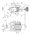
- Fig. 1 is shown schematically a section through a large engine.
- the large engine 100 according to Fig. 1 has a cylinder arrangement with a cylinder in the form of a cylinder liner 20 and a piston 25.
- the cylinder assembly also has a fresh air supply system 101.
- the cylinder arrangement of Fig. 1 is a typical arrangement, as is known in particular for longitudinally flushed two-stroke large diesel engines per se from the prior art.
- the piston 25 is arranged to be movable back and forth along a cylinder wall 22 of the cylinder liner 20.
- the piston 25 performs the reciprocating movement between two reversal points, namely a top dead center (TDC) and a bottom dead center (TDC), wherein the top dead center (TDC) between the bottom dead center (UT) and an outlet valve 102 is arranged.
- the piston 25 comprises a piston ring packing, which in Fig. 2 schematically with only three piston rings 27, 28, 29 is shown, namely with the exhaust valve 102 and thus also a combustion chamber 23 closest first top piston ring 28, which is also referred to as top ring, and the second piston ring 27, with respect to the Exhaust valve 102 in Fig. 2 is arranged below the first piston ring 28 and a further, arranged under the piston ring 27 piston ring 29th
- the combustion chamber 23 is shown at the top by a cylinder cover 103 with an injection nozzle, not shown, by means of which Fuel can be injected into the combustion chamber 23, and the exhaust valve 102, the in Fig. 1 is shown in a closed position limited.
- the piston 25 is connected in a conventional manner via a piston rod 13 with a crosshead 14, from which the reciprocating motion of the piston 25 is transmitted to a crankshaft of the large engine during operation of the large engine.
- the piston rod 13 is guided through a flushing chamber 110, which adjoins the cylinder liner 20 below with respect to the outlet valve 102, and a stuffing box 111, which seals the flushing chamber 110 against an underlying crankshaft space 25, so that no fresh air, symbolized by an arrow 112 can get out of the washing chamber 110 in the crankshaft space 115.
- a turbocharger 113 supplies fresh air to the washing room 110 at a high pressure, for example under a pressure of four bar.
- the piston 25 is designed as an internally cooled with a coolant 70 piston 25, wherein the coolant via supply lines, not shown, and is discharged.
- the piston 25 is in the Fig. 1 displayed in a position between OT and UT.
- the piston upper edge 71 is defined by the uppermost point in the direction of the outlet valve 102 of a lateral surface 72 of the piston 25.
- the piston 25 is arranged in the direction of the bottom dead center along a piston axis in the cylinder liner 20 in the axial direction movable back and forth.
- the piston 25 is constructed in two pieces. It is composed of a so-called piston crown 73 and a so-called piston skirt 74 screwed to the piston crown 73 with screws, not shown, the piston crown 73 being arranged in the direction of the outlet valve and the piston skirt 74 in the direction of the wash chamber 110.
- the piston skirt 74 has a cylindrical lateral surface whose lowest point in the direction of the washing compartment 110 defines a piston skirt lower edge 75.
- piston rings 27, 28, 29 arranged in the direction of exhaust valve first, uppermost piston ring 28, a piston in the direction of piston skirt 75 adjacent second piston ring 29 and a second piston ring 29 in the direction of piston lower edge 75 adjacent third piston ring 27.
- the piston ring 27 is located between the top piston ring 28 and the bottom piston ring 29th
- Lubricant and coolant is transported by the piston rod 13 to the piston 25.
- the lubricant and / or the coolant is the piston rod 13 according to Fig. 1 fed via the crosshead 14.
- the crosshead contains channels that are in Fig. 3 have been shown in detail. These channels are fed via a knee lever 120.
- the toggle lever 120 provides a connection between a fixed reservoir 30 (see FIG Fig. 2 ) and the crosshead 14 is a pump 1 may be provided between the reservoir 30 and the crosshead 14.
- the reservoir 30 may be formed in analogy to a common rail reservoir and contain lubricant or coolant, which is already under a sufficiently high pressure.
- a sufficiently high pressure is meant a pressure which is above the pressure P1 or P2 and which is sufficient to compensate for the pressure losses of the supply line to the crosshead 14.
- the toggle 120 may itself have one or more hinges to compensate for the movement of the crosshead.
- a cylinder of a two-stroke large diesel engine with a lubricating device 10 is shown in section.
- the two-stroke large diesel engine of Fig. 2 comprises a plurality of cylinders 20, wherein for reasons of clarity, only one cylinder 20 is shown by way of example.
- the cylinder 20 comprises a cylinder wall 22 which delimits an inner space 23 of the cylinder 20 in a manner known per se in the circumferential direction.
- a piston 25 is provided, which arranged with respect to an axial direction A of the cylinder 20 along a running surface 21 of the cylinder wall 22 back and forth is.
- the tread 21 may be provided on a surface layer applied to a surface of the cylinder wall 22, for example, by thermal spraying.
- At least one lubrication point 7, 17, in particular a lubricant nozzle 26, 46 is arranged, which is fed by the pump 1 in a conventional manner with lubricant, so that in the operating state, a lubricant film are applied to the running surface 21 of the cylinder wall 22 can.
- the lubrication point 7, 17 is connected via a lubricant line 8, 18 to the pump 1.
- Each of the lubricant lines has a shut-off element 5, 15.
- the lubricant lines are part of a distributor 3, which may also be designed as a common rail memory.
- the pump 1 delivers lubricant from a reservoir 30 through the manifold 3 to the lubrication points 7, 17.
- the same arrangement can be used when, instead of lubricant, coolant is used to cool pistons or cylinders.
- the pump 1 can be operated with lubricant or with servo oil or with coolant. That is, the reservoir 30 provides lubricant or coolant at a pressure of around 20 bar.
- the working piston 33 of the pump 1 is operated with lubricant or coolant which is supplied from a reservoir 31 which is under higher pressure than the reservoir 30.
- the pressure in the reservoir 31 is between 50 and 100 bar, in particular around 50 bar plus the pressure loss of the lines.
- the reservoir 31 may also be used to supply lubricant or coolant to the crosshead via the second connection line.
- a throttle element between the reservoir and the second connecting line is provided to transform from the pressure over to a lower pressure P1, which is a maximum of between 40 and 50 bar for a pulse.
- the lubricant which is fed into the working piston space 34 of the pump 1, passes through an opening 39 in the delivery chamber 36.
- the opening 39 is connected to the working piston space 34 as long as the working piston is in the working piston space 35, ie the stroke the pump 1 has not yet started.
- the working piston in Working piston space 34 is acted upon with lubricant, he sets against the resistance of the return means 37 in motion.
- Each of the openings 39 is closed by the delivery piston 38 and the lubricant located in the delivery chamber 36 is compressed. Since the delivery chamber 36 is in fluid-conducting connection with the distributor 3, the lubricant in the distributor 3 or the lubricant lines 8, 18 is also compressed.
- the lubricant in the lubricant lines 8, 18 has reached the required pressure.
- a pressure sensor in the manifold 3 it can be monitored whether the pressure is within a predetermined range required to ensure lubrication.
- This bandwidth is generally in a range of 10 to 50 bar, in particular this range comprises a base pressure of 10 to 15 bar and a pressure for a pulse which is between 40 and 50 bar.
- the lubricant is thus provided in the lubricant lines 8, 18 so as to be applied to the tread 21 of the cylinder 20 at the desired time.
- the desired time is determined by the central unit 50, which transmits a signal for opening the corresponding shut-off means 5, 15 via the signal transmission lines 42, 43.
- the time of lubrication is completely determined by the central unit.
- the time of closing the shut-off means 5, 15 can also be arbitrarily specified by the central unit 50.
- the amount of lubricant required for this particular lubrication cycle can be accurately adjusted.
- a measuring device 40 is shown with which a characteristic value for the operating state of the two-stroke large diesel engine is detected.
- the measuring device 40 generates an electrical signal which is characteristic of the characteristic value and transmits this signal in a signal transmission line 41 to a central unit 50, which serves to control the lubrication system.
- the signal is in the central unit 50 evaluated. If the evaluation results in a lubricant requirement, a signal is transmitted from the central unit to the shut-off elements 5, 15 via the signal transmission lines 42, 43, so that they are actuated, that is, opened or closed for the flow of lubricant.
- the signal can also be used to control the pump 1.
- rotary pumps such as centrifugal pumps, impeller pumps.
- the speed of a motor driving the pump can be changed, so that the volume flow delivered per unit time by the pump is changed.
- a rotary piston pump usually includes a plurality of pistons which are moved via a camshaft driven by an electric motor. As the rotational speed of the camshaft is increased, the number of piston strokes per unit of time is increased and thus the volume flow delivered by the pump is changed.
- a pump with a single delivery piston can be used, wherein the delivery piston can be movable hydraulically or via a camshaft.
- the switching frequency of the switching valve 32 can be changed.
- a signal will be sent from the CPU 50 to the switching valve 32 via the signal transmission line 44.
- the switching valve 32 is designed in particular as a solenoid valve.
- the switching valve 32 can assume two positions. In the first position, a connection between the working piston 33 and the reservoir 30 is opened, so that lubricant from the working piston space 34, in which the working piston 33 is located, can be returned to the reservoir 30. A connecting line between the reservoir 30 and the delivery chamber 36 is opened so that lubricant can flow into the delivery chamber 36.
- the working piston 33 is brought by a return means 37, here a spring, in its upper end position and is now ready to carry out a delivery stroke.
- a return means 37 here a spring
- the switching valve 32 When the switching valve 32 receives a signal to execute a delivery stroke by a signal from the CPU 50, it switches so that a connection to the reservoir 31 is opened. Lubricant under high pressure is introduced from the reservoir 31 into the working piston space 35 and the working piston 33 carries out a delivery stroke, that is, lubricant is pumped by means of the delivery piston 38 from the delivery chamber into the distributor 3. Furthermore, the working piston does not need to be sealed from the pumping chamber. A seal of the drive-side working piston space 35 against the delivery piston-side working piston space 34 is thus not required.
- the shut-off elements 5, 15 are opened for a certain period of time, so that lubricant is applied to the running surface 21.
- the time duration in which each of the shut-off elements 5, 15 is kept open is individually adaptable and dependent on the measured value which has been detected with the measuring device 40.
- a plurality of measuring devices may be provided which determine different parameters of the large engine.
- the pressure of the lubricant so that it lies between the maximum pressure prevailing in the combustion chamber and the minimum pressure.
- the pressure is in the combustion chamber during at least during the last phase of the compression stroke and at the time of ignition of the fuel-air mixture and at the beginning of the expansion phase above the lubricant pressure, so that no lubricant can enter the combustion chamber. Only when the pressure in the combustion chamber during the expansion phase, the fresh air supply or the first phase of the compression stroke is below the pressure of the lubricant, an entry of lubricant on the tread of the cylinder is possible.
- the piston has passed the lubrication point in the compression stroke, that is, the lubrication point opens into the cylinder space filled with purging air, which is below the corresponding purge air pressure.
- the purge air pressure is usually slightly above the ambient air pressure, usually around 3 bar.
- lubricant may leak into the cylinder space as the piston approaches near top dead center as the lubricant in the cylinder space is delivered is because the pressure scavenging air side is much lower than the combustion chamber side pressure around the cylinder chamber.
- the inventive device 10 serves to lubricate or cool the cylinder liner 20 and / or the piston 25 and / or the connecting elements 13, 14, 19, 120 by means of a fluid medium.
- the fluid medium is in particular a coolant or a lubricant.
- a first connection line for conveying the fluid medium from a reservoir 30 to the place of use 20, 25, 13, 14, 19 is provided.
- the first connecting line 11 extends at least partially through the connecting elements 13, 14, 19.
- the connecting line can be provided in the same way in the crosshead, in the toggle lever and in the piston, in particular in the piston skirt.
- the fluid medium is in the first connection line substantially under the pressure P1.
- a second connecting line 12 is provided, in which a fluid medium is received, which is under a pressure P2.
- the pressure P2 is higher than the maximum pressure P1 in normal operation.
- Fig. 3 shows a detail of the device for cooling and / or lubrication between the first connecting line 11 and second connecting line 12. It is a section of the crosshead 14 shown in section and a part of the piston rod 13. According to Fig. 3 is still a sleeve member 117 between the piston rod 13 and crosshead 14. As the piston rod 13 is rotatable relative to the crosshead 14, seals 118 are provided to seal the first and second connecting lines 11, 12 relative to the crankshaft space 115.
- first connection line 11 is a fluid medium, such as a coolant or a lubricant.
- the fluid medium in the first connection line has the pressure P1.
- the first connecting line extends through the piston rod 13, through the sleeve member 117 and through the crosshead 14.
- On the outer lateral surface of the crosshead is for this purpose an open channel, which represents the connection to the connecting line 11 to the extending through the toggle 120 supply line.
- the supply line and the connection of the supply line to the crosshead are not shown in the drawing.
- a fluid medium which is under the pressure P2.
- the pressure P2 may be constant during normal operation. Since the pressure of the fluid medium in the second connecting line P2 is greater than the pressure P1 of the fluid medium in the first connecting line 11, it is ensured in the first place that the fluid medium of the first connecting line can not escape to the outside. In the event of leakage in the first connection line 11, leakage of the fluid medium is prevented by the higher pressure P2 in the second connection line. In the case of a leak in the first connecting line 11, therefore, fluid medium with the pressure P2 can flow into the first connecting line 11. As a result, the pressure in the first connecting line increases and at the same time the pressure in the second connecting line decreases, thus pressure equalization takes place.
- the pressure drop resulting from the pressure compensation is measured and transmitted to an evaluation unit.
- the evaluation unit continuously compares the measured pressure with the reference pressure. The pressure difference decreases due to the pressure compensation, therefore, the evaluation unit emits an output signal, for example an alarm. This alarm signals a leak in the first connection line.
- the pressure P2 decreases.
- the reduction of the pressure P2 with respect to the reference pressure is measured by the evaluation unit.
- the evaluation unit also generates an output signal, for example an alarm, in this case. This alarm may be different than the alarm signaling a leak in the first connection line.
- Fig. 4 an embodiment is shown, which shows how different pressures P1 and P2 in the first connection line 11 and second connection line 12 can be generated.
- the conveyed by the pump 1 from the reservoir 30 fluid medium is divided by means of a distributor element not shown on the first connecting line 11 and the second distribution line 12.
- the pressure in the pressure line downstream of the pump corresponds to the higher pressure P2.
- a throttle element 125 is provided to lower the pressure in the connecting line 11.
- a pulser 126 may be provided.
- the pulser is used to deliver a pulsed flow.
- the fluid medium is a lubricant, it may be advantageous to dispense the lubricant at certain times.
- the pulser may be formed, for example, as a shut-off, in particular as a valve.
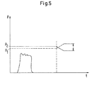
- the graph shown shows the pressure curve of the fluid medium, which is plotted on the y-axis, as a function of time, which is plotted on the x-axis.
- the solid line here indicates the pressure P2 and its change after occurrence of leakage in the second or the first connection line.
- the dot-dash line indicates the pressure P1 and its change in leakage in the first connection line 11.
- the pressure P1 increases in the event of leakage, so that a pressure difference between the pressure P1 stored as reference pressure and caused by the leakage pressure P1 'is formed.
- the graph further shows the pressure curve of a pulse when the fluid medium is to be conveyed in pulses.
- the maximum pressure of a pulse is below the minimum value for the pressure P1 during normal operation of the device.
- inventive device and the method for detecting a leak is not limited to the particular embodiments shown in the figures, but arises for each fluid supply system according to the invention.
Priority Applications (1)
| Application Number | Priority Date | Filing Date | Title |
|---|---|---|---|
| EP13151405.1A EP2626525A1 (fr) | 2012-02-13 | 2013-01-16 | Grand moteur doté d'un dispositif de lubrification de cylindre et procédé de lubrification d'un cylindre d'un grand moteur |
Applications Claiming Priority (2)
| Application Number | Priority Date | Filing Date | Title |
|---|---|---|---|
| EP12155055 | 2012-02-13 | ||
| EP13151405.1A EP2626525A1 (fr) | 2012-02-13 | 2013-01-16 | Grand moteur doté d'un dispositif de lubrification de cylindre et procédé de lubrification d'un cylindre d'un grand moteur |
Publications (1)
| Publication Number | Publication Date |
|---|---|
| EP2626525A1 true EP2626525A1 (fr) | 2013-08-14 |
Family
ID=47504778
Family Applications (1)
| Application Number | Title | Priority Date | Filing Date |
|---|---|---|---|
| EP13151405.1A Withdrawn EP2626525A1 (fr) | 2012-02-13 | 2013-01-16 | Grand moteur doté d'un dispositif de lubrification de cylindre et procédé de lubrification d'un cylindre d'un grand moteur |
Country Status (4)
| Country | Link |
|---|---|
| EP (1) | EP2626525A1 (fr) |
| JP (1) | JP6177537B2 (fr) |
| KR (1) | KR20130093037A (fr) |
| CN (1) | CN103244302B (fr) |
Cited By (3)
| Publication number | Priority date | Publication date | Assignee | Title |
|---|---|---|---|---|
| EP3240957A4 (fr) * | 2014-12-22 | 2018-08-15 | S.P.M. Flow Control, Inc. | Pompe à va-et-vient avec système de lubrification d'extrémité de puissance à double circuit |
| US10087992B2 (en) | 2014-07-25 | 2018-10-02 | S.P.M. Flow Control, Inc. | Bearing system for reciprocating pump and method of assembly |
| USD870157S1 (en) | 2015-07-24 | 2019-12-17 | S.P.M. Flow Control, Inc. | Power end frame segment |
Families Citing this family (1)
| Publication number | Priority date | Publication date | Assignee | Title |
|---|---|---|---|---|
| GB201409064D0 (en) | 2014-05-21 | 2014-07-02 | Castrol Ltd | Method and apparatus |
Citations (6)
| Publication number | Priority date | Publication date | Assignee | Title |
|---|---|---|---|---|
| FR2323093A1 (fr) * | 1975-09-05 | 1977-04-01 | Maschf Augsburg Nuernberg Ag | Alimentation en huile lubrifiante pour une machine |
| EP0903473A1 (fr) * | 1997-09-22 | 1999-03-24 | Wärtsilä NSD Schweiz AG | Moteur diesel et méthode de fonctionnement |
| EP1640571A1 (fr) * | 2004-09-28 | 2006-03-29 | Aisin Seiki Kabushiki Kaisha | Dispositif d'alimentation en huile pour moteur |
| US20070084431A1 (en) * | 2005-10-17 | 2007-04-19 | Omachi Steven T | Fluid pump and method |
| FR2909410A1 (fr) * | 2006-12-05 | 2008-06-06 | Renault Sas | Systeme d'alimentation en huile pour un moteur a combustion intene |
| EP2395208A1 (fr) * | 2010-06-11 | 2011-12-14 | Wärtsilä Schweiz AG | Grand moteur doté d'un dispositif de lubrification de cylindre et procédé de lubrification d'un cylindre d'un grand moteur |
Family Cites Families (2)
| Publication number | Priority date | Publication date | Assignee | Title |
|---|---|---|---|---|
| JPH09264116A (ja) * | 1996-03-29 | 1997-10-07 | Nissan Diesel Motor Co Ltd | 船舶用エンジンの油圧警報装置 |
| JP2000204918A (ja) * | 1999-01-18 | 2000-07-25 | Isuzu Motors Ltd | エンジンのカムシャフト軸受部潤滑構造 |
-
2013
- 2013-01-16 EP EP13151405.1A patent/EP2626525A1/fr not_active Withdrawn
- 2013-02-08 CN CN201310051640.0A patent/CN103244302B/zh not_active Expired - Fee Related
- 2013-02-12 KR KR1020130015023A patent/KR20130093037A/ko not_active Application Discontinuation
- 2013-02-12 JP JP2013024191A patent/JP6177537B2/ja not_active Expired - Fee Related
Patent Citations (6)
| Publication number | Priority date | Publication date | Assignee | Title |
|---|---|---|---|---|
| FR2323093A1 (fr) * | 1975-09-05 | 1977-04-01 | Maschf Augsburg Nuernberg Ag | Alimentation en huile lubrifiante pour une machine |
| EP0903473A1 (fr) * | 1997-09-22 | 1999-03-24 | Wärtsilä NSD Schweiz AG | Moteur diesel et méthode de fonctionnement |
| EP1640571A1 (fr) * | 2004-09-28 | 2006-03-29 | Aisin Seiki Kabushiki Kaisha | Dispositif d'alimentation en huile pour moteur |
| US20070084431A1 (en) * | 2005-10-17 | 2007-04-19 | Omachi Steven T | Fluid pump and method |
| FR2909410A1 (fr) * | 2006-12-05 | 2008-06-06 | Renault Sas | Systeme d'alimentation en huile pour un moteur a combustion intene |
| EP2395208A1 (fr) * | 2010-06-11 | 2011-12-14 | Wärtsilä Schweiz AG | Grand moteur doté d'un dispositif de lubrification de cylindre et procédé de lubrification d'un cylindre d'un grand moteur |
Cited By (11)
| Publication number | Priority date | Publication date | Assignee | Title |
|---|---|---|---|---|
| US10087992B2 (en) | 2014-07-25 | 2018-10-02 | S.P.M. Flow Control, Inc. | Bearing system for reciprocating pump and method of assembly |
| US10393182B2 (en) | 2014-07-25 | 2019-08-27 | S.P.M. Flow Control, Inc. | Power end frame assembly for reciprocating pump |
| US10677244B2 (en) | 2014-07-25 | 2020-06-09 | S.P.M. Flow Control, Inc. | System and method for reinforcing reciprocating pump |
| US11204030B2 (en) | 2014-07-25 | 2021-12-21 | Spm Oil & Gas Inc. | Support for reciprocating pump |
| US11746775B2 (en) | 2014-07-25 | 2023-09-05 | Spm Oil & Gas Inc. | Bearing system for reciprocating pump and method of assembly |
| US11898553B2 (en) | 2014-07-25 | 2024-02-13 | Spm Oil & Gas Inc. | Power end frame assembly for reciprocating pump |
| EP3240957A4 (fr) * | 2014-12-22 | 2018-08-15 | S.P.M. Flow Control, Inc. | Pompe à va-et-vient avec système de lubrification d'extrémité de puissance à double circuit |
| US10352321B2 (en) | 2014-12-22 | 2019-07-16 | S.P.M. Flow Control, Inc. | Reciprocating pump with dual circuit power end lubrication system |
| US11421682B2 (en) | 2014-12-22 | 2022-08-23 | Spm Oil & Gas Inc. | Reciprocating pump with dual circuit power end lubrication system |
| USD870157S1 (en) | 2015-07-24 | 2019-12-17 | S.P.M. Flow Control, Inc. | Power end frame segment |
| USD870156S1 (en) | 2015-07-24 | 2019-12-17 | S.P.M. Flow Control, Inc. | Power end frame segment |
Also Published As
| Publication number | Publication date |
|---|---|
| KR20130093037A (ko) | 2013-08-21 |
| JP6177537B2 (ja) | 2017-08-09 |
| CN103244302A (zh) | 2013-08-14 |
| CN103244302B (zh) | 2017-10-27 |
| JP2013164072A (ja) | 2013-08-22 |
Similar Documents
| Publication | Publication Date | Title |
|---|---|---|
| EP2395208A1 (fr) | Grand moteur doté d'un dispositif de lubrification de cylindre et procédé de lubrification d'un cylindre d'un grand moteur | |
| EP1936245B1 (fr) | Piston doté d'un anneau collecteur d'huile | |
| DE102008045730B4 (de) | Rücklauffreie Kraftstoffpumpeneinheit sowie damit ausgerüstetes Fahrzeug | |
| DE69628979T2 (de) | Brennstoffeinspritzungssystem für Brennkraftmaschine | |
| DE60120403T2 (de) | Vorrichtung und verfahren zur schmierung einer kolbenmaschine | |
| DE102006047977B3 (de) | Verfahren zur Durchführung eines Hochdruckstarts einer Brennkraftmaschine, Steuervorrichtung und Brennkraftmaschine | |
| DE102011055964A1 (de) | Brennstoffzuführpumpe | |
| EP2177720A1 (fr) | Grand moteur diesel | |
| EP2194244A1 (fr) | Dispositif de lubrification et procédé destiné à la lubrification d'une surface de roulement d'une paroi de cylindre | |
| EP2626525A1 (fr) | Grand moteur doté d'un dispositif de lubrification de cylindre et procédé de lubrification d'un cylindre d'un grand moteur | |
| EP2199549A1 (fr) | Dispositif de lubrification de cylindre pour moteur à combustion interne | |
| DE69728270T2 (de) | Brennstoff-gas-gemisch einspritzsystem | |
| EP2551503A1 (fr) | Piston, bague de piston et segment répartiteur d'huile pour moteur à combustion interne à piston élévateur | |
| EP0903473B1 (fr) | Moteur diesel et méthode de fonctionnement | |
| EP2551504A1 (fr) | Piston et segment répartiteur d'huile pour moteur à combustion interne à piston élévateur | |
| EP2664754A1 (fr) | Procédé et dispositif de lubrification de cylindre pour la lubrification d'une unité piston-cylindre d'un moteur à combustion interne à piston élévateur | |
| DE102012101585B4 (de) | Hochdruck-Kraftstoffpumpe | |
| EP2682572B1 (fr) | Système de lubrification | |
| DE2827626A1 (de) | Verfahren beim schmieren der zylinderlaufflaechen einer kolbenmaschine und schmiersystem zur ausuebung dieses verfahrens | |
| DE2303012A1 (de) | Hydraulischer ventilschieber fuer dieselbrennstoff-einspritzpumpen | |
| DE102016119258A1 (de) | Variable spannvorrichtung für nockenantrieb | |
| DE19959309A1 (de) | Motor | |
| EP3652417B1 (fr) | Procédé et dispositif pour détendre un gaz au moyen d'un moteur à piston | |
| EP2410140B1 (fr) | Dispositif de lubrification pour un piston | |
| WO2009112500A1 (fr) | Mécanisme à manivelle |
Legal Events
| Date | Code | Title | Description |
|---|---|---|---|
| PUAI | Public reference made under article 153(3) epc to a published international application that has entered the european phase |
Free format text: ORIGINAL CODE: 0009012 |
|
| AK | Designated contracting states |
Kind code of ref document: A1 Designated state(s): AL AT BE BG CH CY CZ DE DK EE ES FI FR GB GR HR HU IE IS IT LI LT LU LV MC MK MT NL NO PL PT RO RS SE SI SK SM TR |
|
| AX | Request for extension of the european patent |
Extension state: BA ME |
|
| 17P | Request for examination filed |
Effective date: 20140214 |
|
| RBV | Designated contracting states (corrected) |
Designated state(s): AL AT BE BG CH CY CZ DE DK EE ES FI FR GB GR HR HU IE IS IT LI LT LU LV MC MK MT NL NO PL PT RO RS SE SI SK SM TR |
|
| STAA | Information on the status of an ep patent application or granted ep patent |
Free format text: STATUS: EXAMINATION IS IN PROGRESS |
|
| 17Q | First examination report despatched |
Effective date: 20170210 |
|
| GRAP | Despatch of communication of intention to grant a patent |
Free format text: ORIGINAL CODE: EPIDOSNIGR1 |
|
| STAA | Information on the status of an ep patent application or granted ep patent |
Free format text: STATUS: GRANT OF PATENT IS INTENDED |
|
| INTG | Intention to grant announced |
Effective date: 20190527 |
|
| STAA | Information on the status of an ep patent application or granted ep patent |
Free format text: STATUS: THE APPLICATION IS DEEMED TO BE WITHDRAWN |
|
| 18D | Application deemed to be withdrawn |
Effective date: 20191008 |