EP2626176A1 - Système actionneur de déplacement de contact - Google Patents
Système actionneur de déplacement de contact Download PDFInfo
- Publication number
- EP2626176A1 EP2626176A1 EP13156628.3A EP13156628A EP2626176A1 EP 2626176 A1 EP2626176 A1 EP 2626176A1 EP 13156628 A EP13156628 A EP 13156628A EP 2626176 A1 EP2626176 A1 EP 2626176A1
- Authority
- EP
- European Patent Office
- Prior art keywords
- force
- robotic frame
- human body
- robotic
- frame
- Prior art date
- Legal status (The legal status is an assumption and is not a legal conclusion. Google has not performed a legal analysis and makes no representation as to the accuracy of the status listed.)
- Withdrawn
Links
- 238000006073 displacement reaction Methods 0.000 title claims abstract description 40
- 230000033001 locomotion Effects 0.000 claims abstract description 42
- 230000005484 gravity Effects 0.000 claims abstract description 27
- 230000003278 mimic effect Effects 0.000 claims abstract description 9
- 238000000034 method Methods 0.000 claims description 22
- 230000004044 response Effects 0.000 claims description 21
- 238000002485 combustion reaction Methods 0.000 claims description 19
- 239000012530 fluid Substances 0.000 claims description 17
- 230000008859 change Effects 0.000 claims description 11
- 230000007246 mechanism Effects 0.000 claims description 11
- 238000004891 communication Methods 0.000 claims description 6
- 230000035945 sensitivity Effects 0.000 claims description 3
- 210000001364 upper extremity Anatomy 0.000 claims 26
- 230000001276 controlling effect Effects 0.000 description 25
- 210000003414 extremity Anatomy 0.000 description 14
- 239000013598 vector Substances 0.000 description 13
- 210000002414 leg Anatomy 0.000 description 8
- 230000006870 function Effects 0.000 description 7
- 210000001624 hip Anatomy 0.000 description 7
- 230000003993 interaction Effects 0.000 description 7
- 210000004197 pelvis Anatomy 0.000 description 6
- 210000000707 wrist Anatomy 0.000 description 5
- 238000006243 chemical reaction Methods 0.000 description 4
- 210000004247 hand Anatomy 0.000 description 4
- 239000011159 matrix material Substances 0.000 description 4
- 238000005259 measurement Methods 0.000 description 3
- 230000004048 modification Effects 0.000 description 3
- 238000012986 modification Methods 0.000 description 3
- 210000003205 muscle Anatomy 0.000 description 3
- 230000008901 benefit Effects 0.000 description 2
- 210000004556 brain Anatomy 0.000 description 2
- 238000004364 calculation method Methods 0.000 description 2
- 230000007423 decrease Effects 0.000 description 2
- 238000013461 design Methods 0.000 description 2
- 238000010586 diagram Methods 0.000 description 2
- 210000000245 forearm Anatomy 0.000 description 2
- 230000001771 impaired effect Effects 0.000 description 2
- 210000005036 nerve Anatomy 0.000 description 2
- 238000011160 research Methods 0.000 description 2
- 206010073306 Exposure to radiation Diseases 0.000 description 1
- 241000282412 Homo Species 0.000 description 1
- 235000002595 Solanum tuberosum Nutrition 0.000 description 1
- 244000061456 Solanum tuberosum Species 0.000 description 1
- 230000003044 adaptive effect Effects 0.000 description 1
- 230000004075 alteration Effects 0.000 description 1
- 210000003484 anatomy Anatomy 0.000 description 1
- 239000003124 biologic agent Substances 0.000 description 1
- 239000013043 chemical agent Substances 0.000 description 1
- 238000010276 construction Methods 0.000 description 1
- 230000008878 coupling Effects 0.000 description 1
- 238000010168 coupling process Methods 0.000 description 1
- 238000005859 coupling reaction Methods 0.000 description 1
- 230000003247 decreasing effect Effects 0.000 description 1
- 238000011161 development Methods 0.000 description 1
- 230000000694 effects Effects 0.000 description 1
- 230000005611 electricity Effects 0.000 description 1
- 238000002567 electromyography Methods 0.000 description 1
- 238000005516 engineering process Methods 0.000 description 1
- 238000009472 formulation Methods 0.000 description 1
- 239000000446 fuel Substances 0.000 description 1
- 239000007789 gas Substances 0.000 description 1
- 230000007274 generation of a signal involved in cell-cell signaling Effects 0.000 description 1
- 231100001261 hazardous Toxicity 0.000 description 1
- 230000009191 jumping Effects 0.000 description 1
- 210000003127 knee Anatomy 0.000 description 1
- 238000012423 maintenance Methods 0.000 description 1
- 239000000203 mixture Substances 0.000 description 1
- 230000002232 neuromuscular Effects 0.000 description 1
- 235000012015 potatoes Nutrition 0.000 description 1
- 230000004043 responsiveness Effects 0.000 description 1
- 230000007103 stamina Effects 0.000 description 1
- 230000002123 temporal effect Effects 0.000 description 1
- 238000012795 verification Methods 0.000 description 1
Images


Classifications
-
- B—PERFORMING OPERATIONS; TRANSPORTING
- B25—HAND TOOLS; PORTABLE POWER-DRIVEN TOOLS; MANIPULATORS
- B25J—MANIPULATORS; CHAMBERS PROVIDED WITH MANIPULATION DEVICES
- B25J13/00—Controls for manipulators
- B25J13/08—Controls for manipulators by means of sensing devices, e.g. viewing or touching devices
-
- B—PERFORMING OPERATIONS; TRANSPORTING
- B25—HAND TOOLS; PORTABLE POWER-DRIVEN TOOLS; MANIPULATORS
- B25J—MANIPULATORS; CHAMBERS PROVIDED WITH MANIPULATION DEVICES
- B25J9/00—Programme-controlled manipulators
- B25J9/0006—Exoskeletons, i.e. resembling a human figure
-
- A—HUMAN NECESSITIES
- A61—MEDICAL OR VETERINARY SCIENCE; HYGIENE
- A61H—PHYSICAL THERAPY APPARATUS, e.g. DEVICES FOR LOCATING OR STIMULATING REFLEX POINTS IN THE BODY; ARTIFICIAL RESPIRATION; MASSAGE; BATHING DEVICES FOR SPECIAL THERAPEUTIC OR HYGIENIC PURPOSES OR SPECIFIC PARTS OF THE BODY
- A61H1/00—Apparatus for passive exercising; Vibrating apparatus; Chiropractic devices, e.g. body impacting devices, external devices for briefly extending or aligning unbroken bones
- A61H1/02—Stretching or bending or torsioning apparatus for exercising
- A61H1/0237—Stretching or bending or torsioning apparatus for exercising for the lower limbs
- A61H1/024—Knee
-
- A—HUMAN NECESSITIES
- A61—MEDICAL OR VETERINARY SCIENCE; HYGIENE
- A61H—PHYSICAL THERAPY APPARATUS, e.g. DEVICES FOR LOCATING OR STIMULATING REFLEX POINTS IN THE BODY; ARTIFICIAL RESPIRATION; MASSAGE; BATHING DEVICES FOR SPECIAL THERAPEUTIC OR HYGIENIC PURPOSES OR SPECIFIC PARTS OF THE BODY
- A61H1/00—Apparatus for passive exercising; Vibrating apparatus; Chiropractic devices, e.g. body impacting devices, external devices for briefly extending or aligning unbroken bones
- A61H1/02—Stretching or bending or torsioning apparatus for exercising
- A61H1/0237—Stretching or bending or torsioning apparatus for exercising for the lower limbs
- A61H1/0244—Hip
-
- A—HUMAN NECESSITIES
- A61—MEDICAL OR VETERINARY SCIENCE; HYGIENE
- A61H—PHYSICAL THERAPY APPARATUS, e.g. DEVICES FOR LOCATING OR STIMULATING REFLEX POINTS IN THE BODY; ARTIFICIAL RESPIRATION; MASSAGE; BATHING DEVICES FOR SPECIAL THERAPEUTIC OR HYGIENIC PURPOSES OR SPECIFIC PARTS OF THE BODY
- A61H1/00—Apparatus for passive exercising; Vibrating apparatus; Chiropractic devices, e.g. body impacting devices, external devices for briefly extending or aligning unbroken bones
- A61H1/02—Stretching or bending or torsioning apparatus for exercising
- A61H1/0237—Stretching or bending or torsioning apparatus for exercising for the lower limbs
- A61H1/0255—Both knee and hip of a patient, e.g. in supine or sitting position, the feet being moved together in a plane substantially parallel to the body-symmetrical plane
-
- A—HUMAN NECESSITIES
- A61—MEDICAL OR VETERINARY SCIENCE; HYGIENE
- A61H—PHYSICAL THERAPY APPARATUS, e.g. DEVICES FOR LOCATING OR STIMULATING REFLEX POINTS IN THE BODY; ARTIFICIAL RESPIRATION; MASSAGE; BATHING DEVICES FOR SPECIAL THERAPEUTIC OR HYGIENIC PURPOSES OR SPECIFIC PARTS OF THE BODY
- A61H3/00—Appliances for aiding patients or disabled persons to walk about
- A61H3/008—Appliances for aiding patients or disabled persons to walk about using suspension devices for supporting the body in an upright walking or standing position, e.g. harnesses
-
- B—PERFORMING OPERATIONS; TRANSPORTING
- B25—HAND TOOLS; PORTABLE POWER-DRIVEN TOOLS; MANIPULATORS
- B25J—MANIPULATORS; CHAMBERS PROVIDED WITH MANIPULATION DEVICES
- B25J1/00—Manipulators positioned in space by hand
-
- A—HUMAN NECESSITIES
- A61—MEDICAL OR VETERINARY SCIENCE; HYGIENE
- A61H—PHYSICAL THERAPY APPARATUS, e.g. DEVICES FOR LOCATING OR STIMULATING REFLEX POINTS IN THE BODY; ARTIFICIAL RESPIRATION; MASSAGE; BATHING DEVICES FOR SPECIAL THERAPEUTIC OR HYGIENIC PURPOSES OR SPECIFIC PARTS OF THE BODY
- A61H2201/00—Characteristics of apparatus not provided for in the preceding codes
- A61H2201/01—Constructive details
- A61H2201/0173—Means for preventing injuries
- A61H2201/0176—By stopping operation
-
- A—HUMAN NECESSITIES
- A61—MEDICAL OR VETERINARY SCIENCE; HYGIENE
- A61H—PHYSICAL THERAPY APPARATUS, e.g. DEVICES FOR LOCATING OR STIMULATING REFLEX POINTS IN THE BODY; ARTIFICIAL RESPIRATION; MASSAGE; BATHING DEVICES FOR SPECIAL THERAPEUTIC OR HYGIENIC PURPOSES OR SPECIFIC PARTS OF THE BODY
- A61H2201/00—Characteristics of apparatus not provided for in the preceding codes
- A61H2201/12—Driving means
- A61H2201/1238—Driving means with hydraulic or pneumatic drive
-
- A—HUMAN NECESSITIES
- A61—MEDICAL OR VETERINARY SCIENCE; HYGIENE
- A61H—PHYSICAL THERAPY APPARATUS, e.g. DEVICES FOR LOCATING OR STIMULATING REFLEX POINTS IN THE BODY; ARTIFICIAL RESPIRATION; MASSAGE; BATHING DEVICES FOR SPECIAL THERAPEUTIC OR HYGIENIC PURPOSES OR SPECIFIC PARTS OF THE BODY
- A61H2201/00—Characteristics of apparatus not provided for in the preceding codes
- A61H2201/16—Physical interface with patient
- A61H2201/1602—Physical interface with patient kind of interface, e.g. head rest, knee support or lumbar support
- A61H2201/1614—Shoulder, e.g. for neck stretching
- A61H2201/1616—Holding means therefor
-
- A—HUMAN NECESSITIES
- A61—MEDICAL OR VETERINARY SCIENCE; HYGIENE
- A61H—PHYSICAL THERAPY APPARATUS, e.g. DEVICES FOR LOCATING OR STIMULATING REFLEX POINTS IN THE BODY; ARTIFICIAL RESPIRATION; MASSAGE; BATHING DEVICES FOR SPECIAL THERAPEUTIC OR HYGIENIC PURPOSES OR SPECIFIC PARTS OF THE BODY
- A61H2201/00—Characteristics of apparatus not provided for in the preceding codes
- A61H2201/16—Physical interface with patient
- A61H2201/1602—Physical interface with patient kind of interface, e.g. head rest, knee support or lumbar support
- A61H2201/1628—Pelvis
- A61H2201/163—Pelvis holding means therefor
-
- A—HUMAN NECESSITIES
- A61—MEDICAL OR VETERINARY SCIENCE; HYGIENE
- A61H—PHYSICAL THERAPY APPARATUS, e.g. DEVICES FOR LOCATING OR STIMULATING REFLEX POINTS IN THE BODY; ARTIFICIAL RESPIRATION; MASSAGE; BATHING DEVICES FOR SPECIAL THERAPEUTIC OR HYGIENIC PURPOSES OR SPECIFIC PARTS OF THE BODY
- A61H2201/00—Characteristics of apparatus not provided for in the preceding codes
- A61H2201/16—Physical interface with patient
- A61H2201/1602—Physical interface with patient kind of interface, e.g. head rest, knee support or lumbar support
- A61H2201/164—Feet or leg, e.g. pedal
- A61H2201/1642—Holding means therefor
-
- A—HUMAN NECESSITIES
- A61—MEDICAL OR VETERINARY SCIENCE; HYGIENE
- A61H—PHYSICAL THERAPY APPARATUS, e.g. DEVICES FOR LOCATING OR STIMULATING REFLEX POINTS IN THE BODY; ARTIFICIAL RESPIRATION; MASSAGE; BATHING DEVICES FOR SPECIAL THERAPEUTIC OR HYGIENIC PURPOSES OR SPECIFIC PARTS OF THE BODY
- A61H2201/00—Characteristics of apparatus not provided for in the preceding codes
- A61H2201/16—Physical interface with patient
- A61H2201/1602—Physical interface with patient kind of interface, e.g. head rest, knee support or lumbar support
- A61H2201/165—Wearable interfaces
-
- A—HUMAN NECESSITIES
- A61—MEDICAL OR VETERINARY SCIENCE; HYGIENE
- A61H—PHYSICAL THERAPY APPARATUS, e.g. DEVICES FOR LOCATING OR STIMULATING REFLEX POINTS IN THE BODY; ARTIFICIAL RESPIRATION; MASSAGE; BATHING DEVICES FOR SPECIAL THERAPEUTIC OR HYGIENIC PURPOSES OR SPECIFIC PARTS OF THE BODY
- A61H2201/00—Characteristics of apparatus not provided for in the preceding codes
- A61H2201/16—Physical interface with patient
- A61H2201/1657—Movement of interface, i.e. force application means
- A61H2201/1676—Pivoting
-
- A—HUMAN NECESSITIES
- A61—MEDICAL OR VETERINARY SCIENCE; HYGIENE
- A61H—PHYSICAL THERAPY APPARATUS, e.g. DEVICES FOR LOCATING OR STIMULATING REFLEX POINTS IN THE BODY; ARTIFICIAL RESPIRATION; MASSAGE; BATHING DEVICES FOR SPECIAL THERAPEUTIC OR HYGIENIC PURPOSES OR SPECIFIC PARTS OF THE BODY
- A61H2201/00—Characteristics of apparatus not provided for in the preceding codes
- A61H2201/50—Control means thereof
- A61H2201/5007—Control means thereof computer controlled
-
- A—HUMAN NECESSITIES
- A61—MEDICAL OR VETERINARY SCIENCE; HYGIENE
- A61H—PHYSICAL THERAPY APPARATUS, e.g. DEVICES FOR LOCATING OR STIMULATING REFLEX POINTS IN THE BODY; ARTIFICIAL RESPIRATION; MASSAGE; BATHING DEVICES FOR SPECIAL THERAPEUTIC OR HYGIENIC PURPOSES OR SPECIFIC PARTS OF THE BODY
- A61H2201/00—Characteristics of apparatus not provided for in the preceding codes
- A61H2201/50—Control means thereof
- A61H2201/5058—Sensors or detectors
- A61H2201/5061—Force sensors
-
- A—HUMAN NECESSITIES
- A61—MEDICAL OR VETERINARY SCIENCE; HYGIENE
- A61H—PHYSICAL THERAPY APPARATUS, e.g. DEVICES FOR LOCATING OR STIMULATING REFLEX POINTS IN THE BODY; ARTIFICIAL RESPIRATION; MASSAGE; BATHING DEVICES FOR SPECIAL THERAPEUTIC OR HYGIENIC PURPOSES OR SPECIFIC PARTS OF THE BODY
- A61H2201/00—Characteristics of apparatus not provided for in the preceding codes
- A61H2201/50—Control means thereof
- A61H2201/5058—Sensors or detectors
- A61H2201/5069—Angle sensors
-
- A—HUMAN NECESSITIES
- A61—MEDICAL OR VETERINARY SCIENCE; HYGIENE
- A61H—PHYSICAL THERAPY APPARATUS, e.g. DEVICES FOR LOCATING OR STIMULATING REFLEX POINTS IN THE BODY; ARTIFICIAL RESPIRATION; MASSAGE; BATHING DEVICES FOR SPECIAL THERAPEUTIC OR HYGIENIC PURPOSES OR SPECIFIC PARTS OF THE BODY
- A61H2201/00—Characteristics of apparatus not provided for in the preceding codes
- A61H2201/50—Control means thereof
- A61H2201/5058—Sensors or detectors
- A61H2201/5079—Velocity sensors
Definitions
- the invention provides a robot displacement device for use with a robotic frame shaped to approximate and be coupleable to at least a portion of the human body and configured to mimic movement with the human body.
- Said robotic frame is also referred to herein as an exoskeleton.
- the device employs a plurality of linear and rotational force sensors which are attached to the robotic frame near the hands and feet of the frame.
- the sensors detect a baseline controlling interface force status relationship between the sensors and the extremities of the human operator, including a contacting relationship as well as a displaced, non-contacting relationship.
- the sensors then output a force signal to a computation system which is integrated into the robotic frame.
- the computation system calculates a linear and rotational force required to maintain the controlling force status relationship. That system then generates and transmits an actuation signal to a drive system attached to the robotic frame. The drive system then displaces a portion of the robotic frame in order to maintain the controlling force status relationship. Alternatively, where no displacement is desired, but the load on the robotic frame has changed, the drive system increases the linear and rotational forces on the robotic frame as needed to maintain the controlling force status relationship.
- the present invention relates generally to wearable robotic displacement systems. More particularly, the present invention relates to a robotic frame and actuator system that mechanically displaces in proportion to force applied by a user therewith.
- Integrating humans and robotic machines in one system offers a world of opportunities for creating a new generation of assistance technology that can be used in biomedical, industrial, military, and aerospace applications.
- the human component contributes its natural and highly developed control algorithms that implement advanced decision making and sensing mechanisms, while the robotic component offers technological advantages such as power, accuracy and speed.
- An exoskeleton driven by a power source other than the human operator is a class of robot manipulators that amplifies human muscle strength while maintaining human control of the operator's objective.
- the joint system of the exoskeleton should approximate that of the human body and ideally respond to both the amplitude and direction of force of the human operator through some type of human/exoskeleton interface.
- a portion of the robotic exoskeleton research effort has been focused on developing the human/exoskeleton interface through at bioport at the neuromuscular level using electromyography signals as the primary command signal to the system.
- Such systems use bioelectric sensors attached to the skin on the legs to monitor signals transmitted from the brain to the muscles.
- the nerve signal from the brain to the muscles generates a detectable electric current on the skin's surface.
- These currents are picked up by the sensors and sent to a computer that translates the nerve signals into signals that control electric motors at the hips and knees of the exoskeleton.
- the accuracy of the bioelectric sensors can decrease significantly.
- trajectory tracking methods which relied on deriving and solving the dynamic equations of motion. The solutions to those equations are then used to determine a desired trajectory of the exoskeleton required to mirror movement of the human operator.
- High gain position controllers often employing adaptive elements, are used to follow the predefined trajectory of the operator.
- the trajectory tracking methods have two primary drawbacks. First they are computationally intensive. Second, the method is not robust to disturbances or changes in the environment. If the exoskeleton comes into contact with an object or its environment or load changes, the dynamics and trajectory must be recalculated or it will fall over.
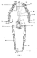
- the exoskeleton frame 100 is shaped to approximate and be coupleable to at least a portion of the human body and configured to mimic movement with the human body.
- the device employs a plurality of force sensors which are attached to the robotic frame 100 near the hands 110 and feet 124 of the frame which are operatively coupled to a central control system 160 and drive system 150.
- the force sensors are capable of detecting linear or rotational forces acting on the robotic frame 100.
- the sensitivity of the force sensors is adjustable.
- the sensors can be configurable to respond only when a force is applied to the force sensor which exceeds a predetermined level.
- IFSR interface force status relationship
- the wrist of the wearer may not be in forceful contact with the corresponding portion of the exoskeleton forearm/wrist when not moving.
- the user needs to apply a force to the exoskeleton as movement is desired - raising an arm or pushing it to the side. This movement results in modification of the non-contacting status of the IFSR, to one of physical contact between the exoskeleton and wrist of the user.
- the exoskeleton will respond to this contact by an appropriate movement to "get out of the way.” Such response may be sequentially repeated many times until the movement of the wrist/forearm is completed. At this point the force status relationship is again stable in the non-contacting position and movement is suspended.
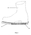
- the foot of the user may be standing on sensors, resulting in a given applied force.
- This IFSR is based on actual contact between the foot and sensor. As the user raises the foot, a non-contacting relationship arises. The exoskeleton will then respond in an effort to reinstate the loaded contact between the foot and its associated exoskeleton component. In this case, therefore, the IFSR is the contacting relationship where the user's foot is forcefully contacting the exoskeleton.
- the sensors are capable of detecting a baseline controlling interface force status relationship between the sensors and the extremities of the human operator.
- the sensors then output a force signal to a central control unit and computational system 160 which is integrated into the robotic frame 100.
- the computation system 160 calculates a linear and rotational force required to maintain the controlling force status relationship whether it is a contacting or non-contacting relationship. That system then generates and transmits an actuation signal to a drive system 150 attached to the robotic frame 100.
- the drive system 150 then displaces a portion of the robotic frame 100 in order to maintain the controlling force status relationship.
- the drive system 150 increases or decreases the linear and rotational forces on the robotic frame 100 as needed to maintain the controlling force status relationship until the movement is completed.
- the present invention allows the wearer to perform activities that he would normally be incapable of or would otherwise have to expend considerable time and energy to perform.
- the system may be worn by military personnel, construction workers, police, medical personnel, and others to support the function or correct the shape of the human body.
- the wearable frame could reduce the number of personnel required in dangerous or hazardous tasks and reduce the physical stress experienced by personnel when executing such tasks.
- the wearable frame could also be configured for application-specific tasks which might involve exposure to radiation, gas, chemical or biological agents.
- the wearable frame could also be used to aid physically impaired individuals in executing otherwise impossible tasks such as sitting, standing or walking.
- the displacement device could serve as a power amplifier, amplifying small motions and forces into controlled, large motions and forces.
- FIG. 1 illustrates a system including a robot displacement device utilizing a plurality of sensors which are attached to a robotic frame 100 and disposed adjacent to or in contact with the human operator near the hands 110 and feet 120.
- sensors are disposed adjacent to or in contact with the human operator near the hips 130 and shoulders 140.
- the sensors 110, 120, 130, and 140 are capable of simultaneously detecting multiple directions of movement of the human operator upon multiple axes.
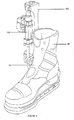
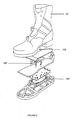
- a human operator may enter the robot displacement device by placing his or her feet into a foot portion 101 of the robotic frame 100 wherein the feet of the operator are in contact with a corresponding force sensor 120.
- FIG. 6 shows the hip portion of the robotic frame 102 and corresponding force sensor 130.
- the operator 52 may be coupled to the frame 100 by a waist strap 103 or other appropriate coupling device. Shown in FIG. 7 , the operator 52 is further coupled to the robotic frame 100 by a shoulder strap 104.
- the force sensor 140 is attached to the robotic frame 100 near the shoulder area of the operator.
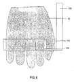
- the hand of the operator 53 grips a handle 105 coupled to the robotic frame 100.
- the force sensor 110 is disposed between the handle 105 and the robotic frame 100. While reference is made herein to force sensors disposed at specific locations on the robotic frame 100, it is understood that the force sensors could be strategically placed at numerous locations at the robotic frame 100 in order to facilitate proper operation of the robotic displacement device.
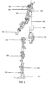
- a central control unit 160 can detect the current joint position and velocity of the robotic frame as well as the force of gravity and direction of gravity relative to the position of the frame. Desired joint position and velocity values of the exoskeleton, responsive to operator movement, are then calculated. Thereafter, the drive system 150 of the device, which may include multiple drive mechanisms positioned at multiple locations on the robotic frame 100, acts in concert with movement of the operator to displace the robotic frame 100. In one exemplary embodiment, drive mechanisms may be disposed proximate to joints 106 of the robotic frame 100 and configured to create a linear or rotational force on a member of the robotic frame 100 in order to create the desired displacement.
- the exoskeleton frame 100 may be displaced in multiple directions and upon multiple axes.
- the central control unit 160 can also serve as a fuel storage device, power generation center and/or a signal generation/processing center. Actual movement of the exoskeleton can be accomplished with delivery of hydraulic fluid through control valves to activate displacement of the robotic frame 100. While specific reference is made herein to hydraulic fluid actuator systems, it is understood that any actuator system capable of moving portions of the exoskeleton are contemplated for use herein.
- the central control unit 160 can calculate a force of the exoskeleton structure 100 exerted on the human operator and also a joint rotational force of the drive system 150 required to counteract the calculated force exerted on the human operator by the robotic frame 100. Thereafter, the drive system 150 exerts the computed rotational force on the joint component of the robotic frame 100 to counteract the force exerted on the human operator by the robotic structure 100.
- an operator of the robotic frame 100 may have a load placed on the back of the robotic frame 100. That load may create a moment force on the robotic frame 100 which would otherwise pull the robotic frame 100 and the human operator down and/or backwards.
- the central control unit 160 is configured to counteract forces placed externally on the robotic frame 100 in order to maintain the robotic frame 100 in an upright position. It is understood, however, that the central control system 160 may be configured to maintain the robotic frame 100 in any desired position (e.g., prone, crouching, and/or sitting).
- control unit 160 of the robot displacement device may be configured to direct power from or to groups of less than all of the force sensors. This would enable the device to essentially "shut down" certain portions of the robotic frame 100 in order to optimize the wearer's desired mode of operation.
- control system 160 is further configured to receive remote signals from a communication device in order to facilitate automatic changes in the mode of operation from a remote observer. For example, a remote observer may send a control signal to the control system 160 commanding the robot displacement device to lay flat or to actuate itself (i.e., over-ride any command signals from the force sensors) thereby ambulating to a location designated by the remote observer or to a predetermined location.
- movement of the robotic frame 100 is accomplished by a drive system 150 disposed proximate to the joints 106 of the robotic frame having, among other things, hydraulic lines and valves.
- the cylinder (not shown) within the drive system 150 can be extended or retracted to adjust the relative position of the robotic frame.
- the hydraulic fluid line and drive mechanism can be pressurized or driven by an internal combustion (IC) engine or other power conversion device.
- IC internal combustion
- a power conversion device includes an engine with a chamber having a primary piston, a rapid response component and a controller operably interconnected to the chamber.
- the chamber can also include at least one fluid port for supplying fluid thereto and an out-take port.
- the primary piston in combination with the fluid port can be configured to provide a variable pressure to the chamber and at least partially facilitate combustion to create energy in a combustion portion of the chamber.
- the primary piston can be configured to reciprocate in the chamber.
- the controller can be configured to control the combustion in the chamber.
- the rapid response component can be in fluid communication with the chamber so that the rapid response component is situated adjacent the combustion portion of the chamber.
- the system can be configured such that a drive system 150 and a power conversion device 180 are located at each joint of the robotic frame 100 and are controlled by signals from the central control unit 130. Also, safety devices such as power interrupts can be included to protect the safety of the personnel wearing the robotic frame.
- FIG. 9 a block diagram is illustrated of the control system and computational means for providing control of the robotic frame while minimizing interaction force applied by the operator of the robotic frame to the robotic frame itself.
- the measured input parameters used by the computational means can include:
- the control law including gravity compensation is used to compute desired torque commands ( ⁇ d 220) that produce the desired results. More specifically, the desired result is to achieve natural, intuitive control while keeping the interaction force between the operator and the exoskeleton many times less than the weight of the payload being transported by the system (except for the component of the weight of the operator itself that must be supported by his feet while standing on the ground).
- J T 260 is the transposed Jacobian matrix which is a function of the exoskeleton joint angles ⁇ 200 with the Jacobian itself relating the translational and angular velocity of some system of reference (e,g., the foot force-moment sensor) relative to another system of reference (e.g. a system of reference attached to the pelvis) and the exoskeleton joints speed ⁇ 210.
- some system of reference e.g., the foot force-moment sensor
- another system of reference e.g. a system of reference attached to the pelvis
- the term g ( ⁇ ) 280 corresponds to the gravity compensation torque command.
- This gravity compensation command is a feed-forward command that provides steady-state weight compensation and allows the payload and the exoskeleton to be supported without using the Force-Moment sensor-based port of the control loop. It can also be used to implement automatic in-field verification of joint torque sensor calibration gain and zero-offset.
- the gravity compensation torque command g ( ⁇ ) 280 depends on the overall exoskeleton and payload configuration in the presence of gravity, and the mass properties of the links and payload, interaction forces and moments between the exoskeleton and the ground, as well as the force-moment interactions between the operator and the exoskeleton.
- F filtered 290 is a low-pass filtered force and moment vector measured by the right or left foot force-moment sensor, and is used as an input parameter for the control system.
- some non-linear, dynamically adjusted low-pass filter parameters are used. Many different implementations of this concept are possible.
- m P g foot 270 is a quantity that is close to the weight of the operator in the right or left foot force-moment sensor frame of reference. In the case of arms, pelvis, or back-mounted load cells, this value is generally set to zero or another desired targeted force-moment (e.g., a value that may result in a forward push exerted by the exoskeleton on the person).
- S L 300 and S R 310 are scaling factors that are used to compute the desired force between the exoskeleton and the operator that must be used by the computational means.
- S L 300 and S R 310 are scaling factors that are used to compute the desired force between the exoskeleton and the operator that must be used by the computational means.
- the left foot and right foot weight distribution factors, S L 300 and S R 310, respectively, are computed using the foot sensors to provide a metric for scaling joint torques, depending on which foot is on the ground or, if both feet are on the ground, the relative weighting of each foot.
- the simple calculation described below consists of taking the respective signed foot sensor reading (positive means a force pushing in the direction of gravity) and dividing it by the sum of both left and right signed foot sensor readings. If the value goes negative (such as when lifting the foot faster than the machine can respond), then it is set equal to zero. If the value becomes greater than positive one, then it is set equal to one. For example, when S L equals 1 and S R equals zero, the person is standing on his left foot and the right foot is raised.
- the scaling factor for the desired component of the force sensed by the force moment sensors can be estimated using the signed value of the component of the force measured by the right and left foot sensors along the gravity vector measured in the frame of reference of the foot sensors.
- the force component used to calculate the scaling factors S L and S R can be obtained in a way similar to that described by the set of equations defined above, but where scalar F x,L and F x,R are replaced by, F PE , L T ⁇ g ⁇ L and F PE , R T ⁇ g ⁇ R , respectively, where F PE,L and F PE,R are the three components of the force between the person and the exoskeleton in the left and right foot sensor frame of reference respectively.
- F PE,L and F PE,R are the three components of the force between the person and the exoskeleton in the left and right foot sensor frame of reference respectively.
- Two series of feedback gain matrices can be used in the embodiment described in this disclosure. These are the sense K, K S 320 and the Force-Moment feedback gain matrix K F 330.
- the sense-K and the Force-Moment feedback matrices are diagonal.
- the elements of the diagonal of K S 320 are equal to zero or are substantially equal in value.
- the characteristics of the sense-K feedback gain matrix basically allow the control system to be activated or turned off (e.g., when the element is zero) and a global gain scalar value to be applied.
- the Force-Moment gain matrix is diagonal. However, all elements of the diagonal may have significantly different values.
- a sliding gains scheme in order to optimize device stability and power, may be implemented.
- High gains are desired for effortless mobility and object manipulation. Used for non-load bearing portions of the system. However, high gains result in poor power.
- Low gains are desired to prevent instability under heavy payloads, used for the load bearing portions of the system. Low gains, however result in decreased mobility and velocity.
- the function f ( s ) varies monotonically from 1 to 0 as s (i.e. the scaling factor S L or S R defined earlier) varies from 0 to 1.
- FIG. 7 One example of such a sliding gain algorithm is illustrated in FIG. 7 and shown below as equation 6.
- SlideGain K HIGH + S L * K LOW - K HIGH / thresh + ⁇
- One example whereby the sliding gains scheme can be implemented includes sensing a change in the controlling interface force status relationship wherein displacement of the robotic device is desired. Thereafter, the system locks a non-moving load bearing portion of the exoskeleton and unlocks a moving non load bearing portion of the exoskeleton. Subsequently, the control system computes a joint rotational force of the unlocked non load-bearing portion of the exoskeleton required to restore the previously sensed controlling interface force status relationship including gravitational forces. The system also computes a joint rotational force of the locked load-bearing portion of the exoskeleton required to ensure the exoskeleton force on the human body is zero.
- the control system generates and transmits a signal to the actuator component of the device and displaces the unlocked non load-bearing portion of the exoskeleton at the computed joint rotational forces. It also actuates the displacement device coupled to the exoskeleton to maintain the computed joint rotational force in the locked load-bearing portion of the exoskeleton.
- the degree to which the joints of the exoskeleton are locked or unlocked is a function of the calculated gains discussed above.
- the final calculated torque ⁇ d 220 is utilized to calculate the desired robotic joint velocity ⁇ d 340 and desire joint position ⁇ d 350 relative to the calculated velocity gain K v 360 and position gain K p 370. Said values are then transmitted to the central control unit 160 of the robotic system 100 and implemented in order to maintain a controlling interface force status relationship between the sensors and the extremities of the human body.
- the present invention can be used in any number of applications that require strength, stamina, and precision enhancement without tethering the operator to a stationary power or control source.
- a method for enabling a wearable human exoskeleton to move in concert with movement of the human body comprises the steps of donning a human exoskeleton and sensing a force status between a plurality of force sensors coupled to the exoskeleton and a contact location near the extremities of the human body. Additionally, the method comprises computing a direction of gravity relative to a portion of the exoskeleton and manually adjusting an exoskeleton human-force response value. Further, the method comprises displacing a portion of the human body relative to the force sensors and sensing a change in the force status.
- the method also comprises locking a non-moving load bearing portion of the exoskeleton, unlocking a moving non load bearing portion of the exoskeleton, computing a joint rotational force of the unlocked non load-bearing portion of the exoskeleton required to restore the force status including gravitational forces, computing a joint rotational force of the locked load-bearing portion of the exoskeleton required to ensure the exoskeleton force on the human body is zero, and generating a signal comprised of at least the calculated joint rotational forces.
- the method comprises transmitting said signal to an actuator system coupled to said exoskeleton and actuating a displacement device coupled to the exoskeleton in response to said signal to displace the unlocked non load bearing portion of the exoskeleton at the computed joint rotational forces. Furthermore, the method comprises actuating the displacement device coupled to the exoskeleton in response to said signal to maintain the computed joint rotational force in the locked load-bearing portion of the exoskeleton and repeating the above steps to mimic movement of the human body.
Landscapes
- Health & Medical Sciences (AREA)
- Rehabilitation Therapy (AREA)
- Life Sciences & Earth Sciences (AREA)
- Veterinary Medicine (AREA)
- Public Health (AREA)
- Epidemiology (AREA)
- Pain & Pain Management (AREA)
- General Health & Medical Sciences (AREA)
- Animal Behavior & Ethology (AREA)
- Physical Education & Sports Medicine (AREA)
- Engineering & Computer Science (AREA)
- Mechanical Engineering (AREA)
- Robotics (AREA)
- Human Computer Interaction (AREA)
- Manipulator (AREA)
- Rehabilitation Tools (AREA)
Applications Claiming Priority (3)
| Application Number | Priority Date | Filing Date | Title |
|---|---|---|---|
| US83147606P | 2006-07-17 | 2006-07-17 | |
| US11/879,448 US8849457B2 (en) | 2006-07-17 | 2007-07-16 | Contact displacement actuator system |
| EP07872565.2A EP2043823B1 (fr) | 2006-07-17 | 2007-07-17 | Système d'actionneur de déplacement à contact |
Related Parent Applications (2)
| Application Number | Title | Priority Date | Filing Date |
|---|---|---|---|
| EP07872565.2 Division | 2007-07-17 | ||
| EP07872565.2A Division-Into EP2043823B1 (fr) | 2006-07-17 | 2007-07-17 | Système d'actionneur de déplacement à contact |
Publications (1)
| Publication Number | Publication Date |
|---|---|
| EP2626176A1 true EP2626176A1 (fr) | 2013-08-14 |
Family
ID=39674636
Family Applications (2)
| Application Number | Title | Priority Date | Filing Date |
|---|---|---|---|
| EP07872565.2A Active EP2043823B1 (fr) | 2006-07-17 | 2007-07-17 | Système d'actionneur de déplacement à contact |
| EP13156628.3A Withdrawn EP2626176A1 (fr) | 2006-07-17 | 2007-07-17 | Système actionneur de déplacement de contact |
Family Applications Before (1)
| Application Number | Title | Priority Date | Filing Date |
|---|---|---|---|
| EP07872565.2A Active EP2043823B1 (fr) | 2006-07-17 | 2007-07-17 | Système d'actionneur de déplacement à contact |
Country Status (6)
| Country | Link |
|---|---|
| US (1) | US8849457B2 (fr) |
| EP (2) | EP2043823B1 (fr) |
| JP (3) | JP5420405B2 (fr) |
| KR (1) | KR101514467B1 (fr) |
| CN (1) | CN101489732B (fr) |
| WO (1) | WO2008094191A2 (fr) |
Cited By (1)
| Publication number | Priority date | Publication date | Assignee | Title |
|---|---|---|---|---|
| CN105501325A (zh) * | 2015-12-17 | 2016-04-20 | 常州大学 | 仿人机器人两自由度并联减振机械足 |
Families Citing this family (102)
| Publication number | Priority date | Publication date | Assignee | Title |
|---|---|---|---|---|
| US8849457B2 (en) * | 2006-07-17 | 2014-09-30 | Raytheon Company | Contact displacement actuator system |
| US20090137933A1 (en) * | 2007-11-28 | 2009-05-28 | Ishoe | Methods and systems for sensing equilibrium |
| AU2008341232B2 (en) | 2007-12-26 | 2015-04-23 | Rex Bionics Limited | Mobility aid |
| US8731716B2 (en) | 2008-08-28 | 2014-05-20 | Raytheon Company | Control logic for biomimetic joint actuators |
| WO2010025419A2 (fr) * | 2008-08-28 | 2010-03-04 | Raytheon Sarcos, Llc | Procédé de calibrage des actionneurs pour une articulation mécanique biomimétique |
| CN102196785B (zh) * | 2008-08-28 | 2014-02-26 | 雷神公司 | 仿生机械关节 |
| ES2335337B1 (es) * | 2009-04-02 | 2011-02-14 | Ikerlan, S.Coop | Dispositivo de deteccion de la intencion de movimiento de un usuario,adaptado a un exoesqueleto. |
| WO2011032363A1 (fr) * | 2009-09-19 | 2011-03-24 | Quan Xiao | Procédé et dispositif pour ressentir une force g variable et créer des sensations de réalité virtuelle en immersion |
| KR101572852B1 (ko) * | 2010-01-06 | 2015-12-01 | 삼성전자 주식회사 | 팔 보조 장치 |
| CN101786478B (zh) * | 2010-02-23 | 2011-09-07 | 华东理工大学 | 具有反力矩结构的虚拟力控制下肢外骨骼机器人 |
| ES2568802T3 (es) | 2010-04-09 | 2016-05-04 | Ekso Bionics | Sistema de manipulación de carga de exoesqueleto y procedimiento de uso |
| JP6008836B2 (ja) * | 2010-04-09 | 2016-10-19 | ロッキード・マーチン・コーポレイションLockheed Martin Corporation | 携帯型荷吊り上げシステム |
| AU2011237357B2 (en) * | 2010-04-09 | 2016-05-19 | Deka Products Limited Partnership | System and apparatus for robotic device and methods of using thereof |
| US9314921B2 (en) | 2011-03-17 | 2016-04-19 | Sarcos Lc | Robotic lift device with human interface operation |
| US9789603B2 (en) | 2011-04-29 | 2017-10-17 | Sarcos Lc | Teleoperated robotic system |
| US8942846B2 (en) | 2011-04-29 | 2015-01-27 | Raytheon Company | System and method for controlling a teleoperated robotic agile lift system |
| US8977388B2 (en) | 2011-04-29 | 2015-03-10 | Sarcos Lc | Platform perturbation compensation |
| US8892258B2 (en) | 2011-04-29 | 2014-11-18 | Raytheon Company | Variable strength magnetic end effector for lift systems |
| US8831794B2 (en) * | 2011-05-04 | 2014-09-09 | Qualcomm Incorporated | Gesture recognition via an ad-hoc proximity sensor mesh for remotely controlling objects |
| US9719633B2 (en) * | 2011-05-06 | 2017-08-01 | Garrett W. Brown | Exoskeleton arm interface |
| KR101290173B1 (ko) * | 2011-10-26 | 2013-07-30 | 한양대학교 에리카산학협력단 | 근력 지원용 착용형 로봇 |
| US20130145530A1 (en) * | 2011-12-09 | 2013-06-13 | Manu Mitra | Iron man suit |
| US9095981B2 (en) | 2012-01-11 | 2015-08-04 | Garrett W. Brown | Load and torque resistant caliper exoskeleton |
| US9616580B2 (en) | 2012-05-14 | 2017-04-11 | Sarcos Lc | End effector for a robotic arm |
| KR20140002840A (ko) * | 2012-06-26 | 2014-01-09 | 한국과학기술연구원 | 물리적 다접촉 상호작용을 위한 링크 메커니즘 |
| KR101250324B1 (ko) | 2012-10-16 | 2013-04-08 | 엘아이지넥스원 주식회사 | 발바닥 센서부를 구비한 착용 로봇 |
| KR101383722B1 (ko) * | 2012-12-17 | 2014-04-08 | 현대자동차(주) | 로봇의 양팔제어방법 |
| KR101371756B1 (ko) * | 2012-12-17 | 2014-03-12 | 현대자동차(주) | 로봇의 보행제어방법 |
| KR101287346B1 (ko) * | 2013-02-20 | 2013-07-23 | 한양대학교 에리카산학협력단 | 근력 지원용 착용형 로봇 |
| KR101287349B1 (ko) * | 2013-02-20 | 2013-07-23 | 한양대학교 에리카산학협력단 | 근력 지원용 착용형 로봇 |
| CN103407588B (zh) * | 2013-08-23 | 2016-12-28 | 电子科技大学 | 一种太空运动辅助装置 |
| JP6284319B2 (ja) * | 2013-08-30 | 2018-02-28 | 三菱重工業株式会社 | パワーアシストスーツ |
| JP6284318B2 (ja) * | 2013-08-30 | 2018-02-28 | 三菱重工業株式会社 | パワーアシストスーツ |
| KR20150039386A (ko) * | 2013-10-02 | 2015-04-10 | 삼성전자주식회사 | 보행 보조 장치 및 보행 보조 장치의 제어방법 |
| RU2552703C2 (ru) * | 2013-10-29 | 2015-06-10 | Федеральное государственное бюджетное военное образовательное учреждение высшего профессионального образования "Военно-технический университет" Министерства обороны Российской Федерации | Универсальный общевойсковой экзоскелет |
| CN103622792A (zh) * | 2013-11-25 | 2014-03-12 | 北京林业大学 | 外骨骼助力机器人的信息采集与控制系统 |
| KR101620146B1 (ko) | 2013-12-13 | 2016-05-12 | 현대자동차주식회사 | 로봇발의 원터치 착탈장치 |
| KR101490885B1 (ko) * | 2013-12-18 | 2015-02-06 | 국방과학연구소 | 보행의도 추정기반 착용로봇 및 그 제어방법 |
| CN103707284B (zh) * | 2013-12-29 | 2016-01-20 | 哈尔滨理工大学 | 佩戴式上肢助力臂及其助力方法 |
| WO2015106278A2 (fr) * | 2014-01-13 | 2015-07-16 | Massachusetts Institute Of Technology | Robot d'aide à des tâches manuelles portable sur le corps |
| FR3016821B1 (fr) * | 2014-01-29 | 2019-08-02 | Robotiques 3 Dimensions | Exosquelette a port frontal et procede d'utilisation d'un tel exosquelette. |
| JP2015157001A (ja) * | 2014-02-25 | 2015-09-03 | シャープ株式会社 | 運動補助装置 |
| CN106102644B (zh) * | 2014-03-17 | 2019-01-11 | 直观外科手术操作公司 | 避免活动范围极限的自动推出 |
| US9149938B1 (en) | 2014-04-11 | 2015-10-06 | Harris Corporation | Robotic exoskeleton with adaptive viscous user coupling |
| JP2017518098A (ja) * | 2014-05-05 | 2017-07-06 | ジェネシス ロボティクス エルエルピー | 歩行を可能にするハンドコントロールを備えたエクソスケルトンスーツ |
| US10766133B2 (en) | 2014-05-06 | 2020-09-08 | Sarcos Lc | Legged robotic device utilizing modifiable linkage mechanism |
| US10391634B2 (en) | 2014-05-16 | 2019-08-27 | Massachusetts Institute Of Technology | Apparatus and method for supporting a human body using supernumerary artificial limbs |
| US10561568B1 (en) | 2014-06-19 | 2020-02-18 | Lockheed Martin Corporation | Exoskeleton system providing for a load transfer when a user is standing and kneeling |
| US9499219B1 (en) | 2014-08-25 | 2016-11-22 | Google Inc. | Touch-down sensing for robotic devices |
| JP6104867B2 (ja) * | 2014-09-19 | 2017-03-29 | Thk株式会社 | ロボット上半身の支持構造 |
| CN104669249B (zh) * | 2015-02-01 | 2016-05-04 | 襄阳新火炬科技有限公司 | 一种液压驱动式机器人 |
| DE112016002060T5 (de) * | 2015-05-05 | 2018-01-18 | Ekso Bionics, Inc. | Sicherstellen eines Eingriffs eines Anwenders in einer bionischen Vorrichtung eines Exoskeletts |
| US10548800B1 (en) | 2015-06-18 | 2020-02-04 | Lockheed Martin Corporation | Exoskeleton pelvic link having hip joint and inguinal joint |
| US10195736B2 (en) | 2015-07-17 | 2019-02-05 | Lockheed Martin Corporation | Variable force exoskeleton hip joint |
| US10518404B2 (en) | 2015-07-17 | 2019-12-31 | Lockheed Martin Corporation | Variable force exoskeleton hip joint |
| KR102481533B1 (ko) | 2015-09-04 | 2022-12-26 | 삼성전자주식회사 | 운동 보조 장치 및 이를 제어하는 방법 |
| US10912346B1 (en) | 2015-11-24 | 2021-02-09 | Lockheed Martin Corporation | Exoskeleton boot and lower link |
| US10124484B1 (en) | 2015-12-08 | 2018-11-13 | Lockheed Martin Corporation | Load-bearing powered exoskeleton using electromyographic control |
| CN105438309B (zh) * | 2015-12-17 | 2017-07-14 | 常州大学 | 仿人机器人两自由度混联抗冲击机械足 |
| FR3053242B1 (fr) * | 2016-07-04 | 2018-06-29 | Commissariat A L`Energie Atomique Et Aux Energies Alternatives | Exosquelette ambulatoire - procede de commande d'un exosquelette ambulatoire |
| CN106112988B (zh) * | 2016-08-18 | 2018-05-22 | 黄河科技学院 | 用于连接四肢外骨骼机构的人体躯干机械外骨骼装置 |
| WO2018065967A1 (fr) * | 2016-10-07 | 2018-04-12 | Rewalk Robotics Ltd. | Dispositifs, systèmes et procédés pour la détection de pression dans un système d'exosquelette |
| US10828767B2 (en) | 2016-11-11 | 2020-11-10 | Sarcos Corp. | Tunable actuator joint modules having energy recovering quasi-passive elastic actuators with internal valve arrangements |
| US10919161B2 (en) | 2016-11-11 | 2021-02-16 | Sarcos Corp. | Clutched joint modules for a robotic system |
| US10765537B2 (en) | 2016-11-11 | 2020-09-08 | Sarcos Corp. | Tunable actuator joint modules having energy recovering quasi-passive elastic actuators for use within a robotic system |
| US10821614B2 (en) | 2016-11-11 | 2020-11-03 | Sarcos Corp. | Clutched joint modules having a quasi-passive elastic actuator for a robotic assembly |
| US11642272B2 (en) * | 2017-03-22 | 2023-05-09 | Ekso Bionics Holdings, Inc. | Mobility assistance devices with automated assessment and adjustment control |
| CN108942879B (zh) * | 2017-05-19 | 2021-03-12 | 中国航天时代电子公司 | 一种可穿戴全关节双向力反馈一体化闭环操控装置和方法 |
| RU2645804C1 (ru) * | 2017-06-07 | 2018-02-28 | Дмитрий Андреевич Журавлёв | Бионический экзоскелет |
| EP3675726A4 (fr) | 2017-08-30 | 2021-04-28 | Lockheed Martin Corporation | Sélection de capteur automatique |
| DE102017123574A1 (de) * | 2017-10-10 | 2019-04-11 | Exoiq Gmbh | System zur muskelkraftunterstützung |
| US10835444B2 (en) * | 2017-11-13 | 2020-11-17 | Free Bionics Taiwan Inc. | Shoe assembly for a walking assist device |
| US10843330B2 (en) | 2017-12-07 | 2020-11-24 | Sarcos Corp. | Resistance-based joint constraint for a master robotic system |
| US11331809B2 (en) | 2017-12-18 | 2022-05-17 | Sarcos Corp. | Dynamically controlled robotic stiffening element |
| WO2019123374A1 (fr) * | 2017-12-21 | 2019-06-27 | Scuola Superiore Di Studi Universitari E Di Perfezionamento Sant'anna | Robot pouvant être porté ayant une architecture de commande perfectionnée |
| CN108542393B (zh) * | 2018-03-30 | 2024-08-02 | 深圳市丞辉威世智能科技有限公司 | 足底传感装置和穿戴式外骨骼 |
| RU187357U1 (ru) * | 2018-04-06 | 2019-03-01 | Федеральное государственное казенное военное образовательное учреждение высшего образования "Военная академия материально-технического обеспечения имени генерала армии А.В. Хрулёва" Министерства обороны Российской Федерации | Устройство крепления потенциально опасных изделий универсального общевойскового экзоскелета |
| CN208799474U (zh) * | 2018-07-05 | 2019-04-30 | 北京京东方光电科技有限公司 | 一种用于人体腿部康复训练的柔性服 |
| US10906191B2 (en) | 2018-12-31 | 2021-02-02 | Sarcos Corp. | Hybrid robotic end effector |
| US11351675B2 (en) | 2018-12-31 | 2022-06-07 | Sarcos Corp. | Robotic end-effector having dynamic stiffening elements for conforming object interaction |
| US11241801B2 (en) | 2018-12-31 | 2022-02-08 | Sarcos Corp. | Robotic end effector with dorsally supported actuation mechanism |
| US10765911B1 (en) | 2019-03-01 | 2020-09-08 | Dustin Hamoy | Core exercise assembly |
| JP7132159B2 (ja) * | 2019-03-11 | 2022-09-06 | 本田技研工業株式会社 | 動作支援装置の制御装置 |
| CN110834318B (zh) * | 2019-11-16 | 2021-06-01 | 兵器工业卫生研究所 | 一种主动助力装甲车救援外骨骼机器人 |
| US11298287B2 (en) | 2020-06-02 | 2022-04-12 | Dephy, Inc. | Systems and methods for a compressed controller for an active exoskeleton |
| US11148279B1 (en) | 2020-06-04 | 2021-10-19 | Dephy, Inc. | Customized configuration for an exoskeleton controller |
| US11147733B1 (en) | 2020-06-04 | 2021-10-19 | Dephy, Inc. | Systems and methods for bilateral wireless communication |
| US11389367B2 (en) * | 2020-06-05 | 2022-07-19 | Dephy, Inc. | Real-time feedback-based optimization of an exoskeleton |
| US12090069B2 (en) | 2020-08-25 | 2024-09-17 | Dephy, Inc. | Systems and methods for a water resistant active exoskeleton |
| US11173093B1 (en) | 2020-09-16 | 2021-11-16 | Dephy, Inc. | Systems and methods for an active exoskeleton with local battery |
| US20220176559A1 (en) | 2020-12-07 | 2022-06-09 | Sarcos Corp. | Method for Redundant Control Policies for Safe Operation of an Exoskeleton |
| US20220176561A1 (en) | 2020-12-07 | 2022-06-09 | Sarcos Corp. | Sensor Suite Discrepancy Detection System for Safe Operation of an Exoskeleton |
| US11833676B2 (en) | 2020-12-07 | 2023-12-05 | Sarcos Corp. | Combining sensor output data to prevent unsafe operation of an exoskeleton |
| US20220176547A1 (en) | 2020-12-07 | 2022-06-09 | Sarcos Corp. | Method for Sensor Suite Discrepancy Detection and Safe Operation of a Robotic Exoskeleton |
| US20220176558A1 (en) | 2020-12-07 | 2022-06-09 | Sarcos Corp. | Redundant Control Policies for Safe Operation of an Exoskeleton |
| US11794345B2 (en) | 2020-12-31 | 2023-10-24 | Sarcos Corp. | Unified robotic vehicle systems and methods of control |
| DE112021007650T5 (de) * | 2021-07-21 | 2024-04-11 | Fanuc Corporation | Roboter-steuerungsvorrichtung, die den roboter auf der grundlage von vorrichtungsdaten steuert, und korrekturvorrichtung für das betriebsprogramm |
| USD1005361S1 (en) | 2021-08-13 | 2023-11-21 | Festool Gmbh | Wearable robotic exoskeleton with belts |
| US11826907B1 (en) | 2022-08-17 | 2023-11-28 | Sarcos Corp. | Robotic joint system with length adapter |
| US11717956B1 (en) | 2022-08-29 | 2023-08-08 | Sarcos Corp. | Robotic joint system with integrated safety |
| US11897132B1 (en) | 2022-11-17 | 2024-02-13 | Sarcos Corp. | Systems and methods for redundant network communication in a robot |
| US11924023B1 (en) | 2022-11-17 | 2024-03-05 | Sarcos Corp. | Systems and methods for redundant network communication in a robot |
Citations (5)
| Publication number | Priority date | Publication date | Assignee | Title |
|---|---|---|---|---|
| DE102004029513B3 (de) * | 2004-06-18 | 2005-09-29 | Fraunhofer-Gesellschaft zur Förderung der angewandten Forschung e.V. | Vorrichtung zur autarken Eigenfortbewegungsunterstützung und/oder -kontrolle eines gehbehinderten Menschen |
| US6957631B2 (en) | 2001-07-05 | 2005-10-25 | Sarcos Investments Lc | Rapid response power conversion device |
| US20060052732A1 (en) * | 2004-09-08 | 2006-03-09 | Honda Motor Co., Ltd. | Walking assistance device provided with a force sensor |
| US20060130594A1 (en) * | 2004-12-17 | 2006-06-22 | Honda Motor Co., Ltd. | Support moment control method for leg motion support orthosis |
| US7066116B2 (en) | 2004-07-29 | 2006-06-27 | Sarcos Investments Lc | Valve system for a rapid response power conversion device |
Family Cites Families (38)
| Publication number | Priority date | Publication date | Assignee | Title |
|---|---|---|---|---|
| US3358678A (en) * | 1964-07-29 | 1967-12-19 | Kultsar Emery | Moving and support system for the human body |
| US3449769A (en) * | 1966-06-27 | 1969-06-17 | Cornell Aeronautical Labor Inc | Powered exoskeletal apparatus for amplifying human strength in response to normal body movements |
| US3535711A (en) * | 1967-11-01 | 1970-10-27 | Gen Electric | Cutaneous stimuli sensor and transmission network |
| JPS63150175A (ja) * | 1986-12-15 | 1988-06-22 | 工業技術院長 | 歩行ロボツトの脚機構 |
| US5101427A (en) * | 1988-11-16 | 1992-03-31 | Canon Kabushiki Kaisha | Communication apparatus connected to ISDN |
| JPH03165765A (ja) * | 1989-11-27 | 1991-07-17 | Koyou Sokushin Jigyodan | 介護作業補助装置 |
| US5117814A (en) * | 1990-03-16 | 1992-06-02 | Q-Motus, Inc. | Dynamic splint |
| JPH0413580A (ja) * | 1990-04-28 | 1992-01-17 | Sumitomo Heavy Ind Ltd | 建築作業用マニピュレータ |
| US5101472A (en) * | 1990-10-04 | 1992-03-31 | Repperger Daniel W | Military robotic controller with majorizing function and nonlinear torque capability |
| US5282460A (en) * | 1992-01-06 | 1994-02-01 | Joyce Ann Boldt | Three axis mechanical joint for a power assist device |
| US5516249A (en) * | 1994-05-10 | 1996-05-14 | Technical Research Associates, Inc. | Exoskeleton with kinesthetic feedback and robotic control |
| JP2761574B2 (ja) * | 1994-07-06 | 1998-06-04 | 工業技術院長 | 力補助装置の制御方法及びその装置 |
| JP3706655B2 (ja) | 1994-09-09 | 2005-10-12 | 本田技研工業株式会社 | リンク装置及び人工ハンド |
| CN1067001C (zh) * | 1995-09-11 | 2001-06-13 | 株式会社安川电机 | 机器人控制方法 |
| US5865770A (en) * | 1995-12-06 | 1999-02-02 | Schectman; Leonard A. | Device to counteract paralysis |
| JPH1142259A (ja) * | 1997-07-28 | 1999-02-16 | Technol Res Assoc Of Medical & Welfare Apparatus | 歩行補助装具 |
| US6016385A (en) * | 1997-08-11 | 2000-01-18 | Fanu America Corp | Real time remotely controlled robot |
| JPH1156931A (ja) | 1997-08-21 | 1999-03-02 | Tadao Totsuka | 移搬支援ロボット |
| JP3999888B2 (ja) * | 1998-02-24 | 2007-10-31 | 松下電工株式会社 | 抱き上げ補助装置及びその制御方法 |
| JP2000070312A (ja) * | 1998-09-02 | 2000-03-07 | Yamaha Motor Co Ltd | 介護用補助装置 |
| US6890747B2 (en) * | 2000-10-23 | 2005-05-10 | Warner-Lambert Company | Phosphoinositide 3-kinases |
| JP3701582B2 (ja) * | 2001-05-22 | 2005-09-28 | 独立行政法人科学技術振興機構 | イグゾスケルトン装置、イグゾスケルトンサイボーグ装置及び、イグゾスケルトンサイボーグシステム |
| JP4188607B2 (ja) | 2001-06-27 | 2008-11-26 | 本田技研工業株式会社 | 二足歩行移動体の床反力推定方法及び二足歩行移動体の関節モーメント推定方法 |
| WO2003032833A1 (fr) * | 2001-10-16 | 2003-04-24 | Honda Giken Kogyo Kabushiki Kaisha | Dispositif et procede pour determiner une condition de marche |
| FR2839916B1 (fr) | 2002-05-22 | 2004-10-15 | Agence Spatiale Europeenne | Exosquelette pour bras humain, notamment pour des applications spatiales |
| JP2004105261A (ja) | 2002-09-13 | 2004-04-08 | Matsushita Electric Ind Co Ltd | 身体装着型パワーアシスト機器 |
| US7402142B2 (en) * | 2002-09-23 | 2008-07-22 | Honda Giken Kogyo Kabushiki Kaisha | Method and processor for obtaining moments and torques in a biped walking system |
| US7396337B2 (en) * | 2002-11-21 | 2008-07-08 | Massachusetts Institute Of Technology | Powered orthotic device |
| US6966882B2 (en) * | 2002-11-25 | 2005-11-22 | Tibion Corporation | Active muscle assistance device and method |
| JP4120008B2 (ja) * | 2003-02-25 | 2008-07-16 | 独立行政法人科学技術振興機構 | 運動機能補助装置 |
| KR20060015557A (ko) * | 2003-04-28 | 2006-02-17 | 스티븐 제임스 크램톤 | 외골격을 구비한 cmm 암 |
| US7628218B2 (en) | 2003-07-17 | 2009-12-08 | Roynat Inc. | Apparatus for attaching a ground-engaging tool to an implement frame |
| US7549969B2 (en) * | 2003-09-11 | 2009-06-23 | The Cleveland Clinic Foundation | Apparatus for assisting body movement |
| JP4503311B2 (ja) | 2004-02-25 | 2010-07-14 | 本田技研工業株式会社 | 脚体運動補助装具の発生トルク制御方法 |
| JP4107595B2 (ja) * | 2004-08-12 | 2008-06-25 | 茨城県 | 擬似ウェアラブルリフト |
| US20090149783A1 (en) * | 2004-11-30 | 2009-06-11 | Eidgenossische Technische Hochschule Zurich | System And Method For A Cooperative Arm Therapy And Corresponding Rotation Module |
| JP4541867B2 (ja) | 2004-12-16 | 2010-09-08 | 本田技研工業株式会社 | 外力制御方法、外力制御システム及び外力制御プログラム |
| US8849457B2 (en) * | 2006-07-17 | 2014-09-30 | Raytheon Company | Contact displacement actuator system |
-
2007
- 2007-07-16 US US11/879,448 patent/US8849457B2/en active Active
- 2007-07-17 EP EP07872565.2A patent/EP2043823B1/fr active Active
- 2007-07-17 WO PCT/US2007/016336 patent/WO2008094191A2/fr active Application Filing
- 2007-07-17 JP JP2009520827A patent/JP5420405B2/ja active Active
- 2007-07-17 CN CN200780027195.7A patent/CN101489732B/zh not_active Expired - Fee Related
- 2007-07-17 KR KR1020097003178A patent/KR101514467B1/ko active IP Right Grant
- 2007-07-17 EP EP13156628.3A patent/EP2626176A1/fr not_active Withdrawn
-
2012
- 2012-11-12 JP JP2012248425A patent/JP2013082065A/ja active Pending
-
2014
- 2014-09-29 JP JP2014198301A patent/JP2015027730A/ja active Pending
Patent Citations (5)
| Publication number | Priority date | Publication date | Assignee | Title |
|---|---|---|---|---|
| US6957631B2 (en) | 2001-07-05 | 2005-10-25 | Sarcos Investments Lc | Rapid response power conversion device |
| DE102004029513B3 (de) * | 2004-06-18 | 2005-09-29 | Fraunhofer-Gesellschaft zur Förderung der angewandten Forschung e.V. | Vorrichtung zur autarken Eigenfortbewegungsunterstützung und/oder -kontrolle eines gehbehinderten Menschen |
| US7066116B2 (en) | 2004-07-29 | 2006-06-27 | Sarcos Investments Lc | Valve system for a rapid response power conversion device |
| US20060052732A1 (en) * | 2004-09-08 | 2006-03-09 | Honda Motor Co., Ltd. | Walking assistance device provided with a force sensor |
| US20060130594A1 (en) * | 2004-12-17 | 2006-06-22 | Honda Motor Co., Ltd. | Support moment control method for leg motion support orthosis |
Cited By (1)
| Publication number | Priority date | Publication date | Assignee | Title |
|---|---|---|---|---|
| CN105501325A (zh) * | 2015-12-17 | 2016-04-20 | 常州大学 | 仿人机器人两自由度并联减振机械足 |
Also Published As
| Publication number | Publication date |
|---|---|
| US8849457B2 (en) | 2014-09-30 |
| US20090210093A1 (en) | 2009-08-20 |
| EP2043823A2 (fr) | 2009-04-08 |
| EP2043823B1 (fr) | 2014-06-25 |
| KR101514467B1 (ko) | 2015-04-22 |
| JP5420405B2 (ja) | 2014-02-19 |
| WO2008094191A3 (fr) | 2008-10-02 |
| JP2013082065A (ja) | 2013-05-09 |
| JP2015027730A (ja) | 2015-02-12 |
| WO2008094191A2 (fr) | 2008-08-07 |
| JP2009543706A (ja) | 2009-12-10 |
| CN101489732B (zh) | 2015-01-28 |
| KR20090040338A (ko) | 2009-04-23 |
| CN101489732A (zh) | 2009-07-22 |
| EP2043823A4 (fr) | 2010-06-02 |
Similar Documents
| Publication | Publication Date | Title |
|---|---|---|
| EP2043823B1 (fr) | Système d'actionneur de déplacement à contact | |
| JP2009543706A5 (fr) | ||
| Ko et al. | Waist-assistive exoskeleton powered by a singular actuation mechanism for prevention of back-injury | |
| Low et al. | Development of NTU wearable exoskeleton system for assistive technologies | |
| Kazerooni et al. | That which does not stabilize, will only make us stronger | |
| EP2762123B1 (fr) | Dispositif d'aide au mouvement et procédé d'aide au mouvement, programme d'ordinateur et support de stockage de programme | |
| EP2616115B1 (fr) | Utilisation d'une interface homme-machine pour un exosquelette humain | |
| Tanaka et al. | Smart suit: Soft power suit with semi-active assist mechanism-prototype for supporting waist and knee joint | |
| Di et al. | Fall detection and prevention in the elderly based on the ZMP stability control | |
| Wang et al. | PALExo: A parallel actuated lower limb exoskeleton for high-load carrying | |
| Saccares et al. | A novel human effort estimation method for knee assistive exoskeletons | |
| US20240033158A1 (en) | Lower extremity exoskeleton with integrated poles and sit to stand chair | |
| Nakamura et al. | Realizing model-based wearable antigravity muscles support with dynamics terms | |
| Kazerooni | A review of the exoskeleton and human augmentation technology | |
| Huang et al. | Hybrid control of the Berkeley lower extremity exoskeleton (BLEEX) | |
| Ahmed et al. | Survey of on-line control strategies of human-powered augmentation exoskeleton systems | |
| Yatsun et al. | Investigation of human cargo handling in industrial exoskeleton | |
| Zhang et al. | Design concepts and functional particularities of wearable walking assist devices and power-assist suits—a review | |
| Tagliamonte et al. | Force control of a robot for wrist rehabilitation: Towards coping with human intrinsic constraints | |
| Yali et al. | Kinematics analysis of lower extremity exoskeleton | |
| KR101500946B1 (ko) | 허리작업 부하경감을 위한 파워스틱 및 그 제어방법 | |
| Chu | Design of the Berkeley lower extremity exoskeleton (BLEEX) | |
| Nakamura et al. | Control of model-based wearable anti-gravity muscles support system for standing up motion | |
| Di et al. | Real-time fall and overturn prevention control for human-cane robotic system | |
| Masaoka et al. | Basic Verification of Contact Force-Based Control with Full Body-Worn Assistive Robot |
Legal Events
| Date | Code | Title | Description |
|---|---|---|---|
| PUAI | Public reference made under article 153(3) epc to a published international application that has entered the european phase |
Free format text: ORIGINAL CODE: 0009012 |
|
| AC | Divisional application: reference to earlier application |
Ref document number: 2043823 Country of ref document: EP Kind code of ref document: P |
|
| AK | Designated contracting states |
Kind code of ref document: A1 Designated state(s): AT BE BG CH CY CZ DE DK EE ES FI FR GB GR HU IE IS IT LI LT LU LV MC MT NL PL PT RO SE SI SK TR |
|
| 17P | Request for examination filed |
Effective date: 20140211 |
|
| RBV | Designated contracting states (corrected) |
Designated state(s): AT BE BG CH CY CZ DE DK EE ES FI FR GB GR HU IE IS IT LI LT LU LV MC MT NL PL PT RO SE SI SK TR |
|
| STAA | Information on the status of an ep patent application or granted ep patent |
Free format text: STATUS: THE APPLICATION IS DEEMED TO BE WITHDRAWN |
|
| 18D | Application deemed to be withdrawn |
Effective date: 20150203 |