EP2623451A2 - Buchbindesystem - Google Patents
Buchbindesystem Download PDFInfo
- Publication number
- EP2623451A2 EP2623451A2 EP13153442.2A EP13153442A EP2623451A2 EP 2623451 A2 EP2623451 A2 EP 2623451A2 EP 13153442 A EP13153442 A EP 13153442A EP 2623451 A2 EP2623451 A2 EP 2623451A2
- Authority
- EP
- European Patent Office
- Prior art keywords
- sheet
- text
- aligner
- sheets
- conveyance direction
- Prior art date
- Legal status (The legal status is an assumption and is not a legal conclusion. Google has not performed a legal analysis and makes no representation as to the accuracy of the status listed.)
- Granted
Links
Images






Classifications
-
- B—PERFORMING OPERATIONS; TRANSPORTING
- B42—BOOKBINDING; ALBUMS; FILES; SPECIAL PRINTED MATTER
- B42C—BOOKBINDING
- B42C9/00—Applying glue or adhesive peculiar to bookbinding
- B42C9/0006—Applying glue or adhesive peculiar to bookbinding by applying adhesive to a stack of sheets
- B42C9/0012—Applying glue or adhesive peculiar to bookbinding by applying adhesive to a stack of sheets with a roller
- B42C9/0018—Applying glue or adhesive peculiar to bookbinding by applying adhesive to a stack of sheets with a roller for binding stacks of sheets one at the time
- B42C9/0025—Applying glue or adhesive peculiar to bookbinding by applying adhesive to a stack of sheets with a roller for binding stacks of sheets one at the time and subsequently applying a cover
-
- B—PERFORMING OPERATIONS; TRANSPORTING
- B42—BOOKBINDING; ALBUMS; FILES; SPECIAL PRINTED MATTER
- B42C—BOOKBINDING
- B42C1/00—Collating or gathering sheets combined with processes for permanently attaching together sheets or signatures or for interposing inserts
- B42C1/12—Machines for both collating or gathering and permanently attaching together the sheets or signatures
-
- B—PERFORMING OPERATIONS; TRANSPORTING
- B42—BOOKBINDING; ALBUMS; FILES; SPECIAL PRINTED MATTER
- B42C—BOOKBINDING
- B42C11/00—Casing-in
- B42C11/04—Machines or equipment for casing-in or applying covers to books
-
- B—PERFORMING OPERATIONS; TRANSPORTING
- B42—BOOKBINDING; ALBUMS; FILES; SPECIAL PRINTED MATTER
- B42C—BOOKBINDING
- B42C19/00—Multi-step processes for making books
- B42C19/02—Multi-step processes for making books starting with single sheets
-
- B—PERFORMING OPERATIONS; TRANSPORTING
- B65—CONVEYING; PACKING; STORING; HANDLING THIN OR FILAMENTARY MATERIAL
- B65H—HANDLING THIN OR FILAMENTARY MATERIAL, e.g. SHEETS, WEBS, CABLES
- B65H31/00—Pile receivers
- B65H31/34—Apparatus for squaring-up piled articles
- B65H31/38—Apparatus for vibrating or knocking the pile during piling
-
- B—PERFORMING OPERATIONS; TRANSPORTING
- B42—BOOKBINDING; ALBUMS; FILES; SPECIAL PRINTED MATTER
- B42D—BOOKS; BOOK COVERS; LOOSE LEAVES; PRINTED MATTER CHARACTERISED BY IDENTIFICATION OR SECURITY FEATURES; PRINTED MATTER OF SPECIAL FORMAT OR STYLE NOT OTHERWISE PROVIDED FOR; DEVICES FOR USE THEREWITH AND NOT OTHERWISE PROVIDED FOR; MOVABLE-STRIP WRITING OR READING APPARATUS
- B42D1/00—Books or other bound products
- B42D1/003—Books or other bound products characterised by shape or material of the sheets
- B42D1/006—Books or other bound products characterised by shape or material of the sheets with at least one foldable or folded sheet
-
- B—PERFORMING OPERATIONS; TRANSPORTING
- B65—CONVEYING; PACKING; STORING; HANDLING THIN OR FILAMENTARY MATERIAL
- B65H—HANDLING THIN OR FILAMENTARY MATERIAL, e.g. SHEETS, WEBS, CABLES
- B65H2511/00—Dimensions; Position; Numbers; Identification; Occurrences
- B65H2511/10—Size; Dimensions
- B65H2511/11—Length
-
- B—PERFORMING OPERATIONS; TRANSPORTING
- B65—CONVEYING; PACKING; STORING; HANDLING THIN OR FILAMENTARY MATERIAL
- B65H—HANDLING THIN OR FILAMENTARY MATERIAL, e.g. SHEETS, WEBS, CABLES
- B65H2511/00—Dimensions; Position; Numbers; Identification; Occurrences
- B65H2511/20—Location in space
-
- B—PERFORMING OPERATIONS; TRANSPORTING
- B65—CONVEYING; PACKING; STORING; HANDLING THIN OR FILAMENTARY MATERIAL
- B65H—HANDLING THIN OR FILAMENTARY MATERIAL, e.g. SHEETS, WEBS, CABLES
- B65H2701/00—Handled material; Storage means
- B65H2701/10—Handled articles or webs
- B65H2701/11—Dimensional aspect of article or web
- B65H2701/112—Section geometry
- B65H2701/1123—Folded article or web
- B65H2701/11232—Z-folded
-
- B—PERFORMING OPERATIONS; TRANSPORTING
- B65—CONVEYING; PACKING; STORING; HANDLING THIN OR FILAMENTARY MATERIAL
- B65H—HANDLING THIN OR FILAMENTARY MATERIAL, e.g. SHEETS, WEBS, CABLES
- B65H2801/00—Application field
- B65H2801/24—Post -processing devices
- B65H2801/27—Devices located downstream of office-type machines
-
- G—PHYSICS
- G03—PHOTOGRAPHY; CINEMATOGRAPHY; ANALOGOUS TECHNIQUES USING WAVES OTHER THAN OPTICAL WAVES; ELECTROGRAPHY; HOLOGRAPHY
- G03G—ELECTROGRAPHY; ELECTROPHOTOGRAPHY; MAGNETOGRAPHY
- G03G2215/00—Apparatus for electrophotographic processes
- G03G2215/00362—Apparatus for electrophotographic processes relating to the copy medium handling
- G03G2215/00919—Special copy medium handling apparatus
- G03G2215/00936—Bookbinding
Definitions
- the present invention relates to a bookbinding system configured to align sheets to perform bookbinding.
- Such a bookbinding system usually allows a manual-feed sheet (e.g., pre-folded sheet) to be inserted through a manual insertion slot.
- a manual-feed sheet e.g., pre-folded sheet
- Such a bookbinding system has an aligner configured to align the text sheets conveyed by the bookbinding system and the manual-feed sheet inserted through the manual insertion slot.
- the sheets are placed on an alignment tray included in the aligner to be aligned. Then, edges of the bound book except for the spine side are cut off, which forms it into a finished book with a prescribe size.
- a user when placing a manual-feed sheet on the alignment tray, a user places it so that it butts against a predetermined position of the alignment tray.
- a manual-feed sheet whose total length in the alignment direction is shorter than the text sheets, the user places the sheet so that a rotating paddle provided above the sheet causes the sheet to butt against the predetermined position,
- a bookbinding system including an aligner configured to align text sheets to be bound into a bound book; and a controller configured to control the aligner, wherein the controller: determines whether or not a text sheet to be conveyed to the aligner is a pre-folded sheet; determines, when the text sheet to be conveyed to the aligner is the pre-folded sheet, whether or not the length of the pre-folded sheet in a conveyance direction is shorter than a prescribed length from a spine side to a page opening side of text sheets in the bound book after its side edges of the text sheets have been cut off; and switches, when the length of the pre-folded sheet in the conveyance direction is shorter than the prescribed length, alignment procedures in the aligner.
- the aligner includes a rear end member located on an upstream side in the conveyance direction of the text sheet that has been accommodated, and a front end member located on a downstream side in the conveyance direction of the accommodated text sheet, and when the length of the pre-folded sheet in the conveyance direction is shorter than the prescribed length, the controller: moves the accommodated text sheet toward the rear end member side by moving the front end member from a home position toward the rear end member side; returns the front end member to the home position; conveys the pre-folded sheet to the aligner; and moves the accommodated text sheet toward the front end member side by moving the rear end member toward the front end member side.
- the controller interrupts a bookbinding operation and warns a user, when the length of the pre-folded sheet in the conveyance direction is not shorter than the prescribed length.
- the alignment procedure in the aligner is switched when the length of pre-folded sheet in the conveyance direction is shorter than the prescribed length from the spine side to the page opening side of the text sheets in the bound book after the side edges of the text sheets have been cut off. Therefore, a bookbinding system can be provided which prevents the folded part of pre-folded sheet bound in the book from being cut off, when cutting the edges of the bound book after binding.
- moving the front end member and the rear end member allows the front end positions in the conveyance direction of the text sheets and the pre-folded sheet to be aligned. Therefore, a bookbinding system which prevents the folded part of pre-folded sheet from being cut off can be provided by a simple mechanism without using a special device or performing a special operation procedure.
- a bookbinding system can be provided which reliably prevents the pre-folded sheet from being cut off.
- sheets of any size may be applied as text sheets.
- printing may be performed by stencil printing or ink-jet, for example, other printing technique will do, and the printing form is not particularly limited by the present invention.
- the type or number of sheets of the printed matter to be bound is not particularly limited.
- a "manual-feed sheet" in the following description refers to a pre-folded sheet which has been multi-folded except for the edge of the spine side, such as a so-called Z-folded or two-folded sheet,
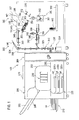
- FIG. 1 is a schematic overall configuration diagram of a bookbinding system 100 of the embodiment (referred to as the present embodiment in the following) of the present invention.
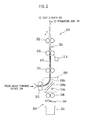
- FIG. 2 is a configuration diagram of a sheet conveyer 310, a cutting unit 330, and a conveyance switching mechanism 338 of the bookbinding system 100 of the present embodiment.
- FIG. 3 (a) is an explanatory diagram showing the printing order of text sheets when inserting a manual-feed sheet between the front cover sheet and the top page with right-side binding.
- FIG. 3(b) is a perspective view explaining how the text sheets are stacked face up when inserting a manual-feed sheet between the front cover sheet and the top page with right-side binding.
- FIG. 1 is a schematic overall configuration diagram of a bookbinding system 100 of the embodiment (referred to as the present embodiment in the following) of the present invention.
- FIG. 2 is a configuration diagram of a sheet conveyer 310, a cutting unit 330, and a conveyance switching mechanism 338 of the bookbind
- FIG. 4(a) is an explanatory diagram showing the printing order of text sheets when inserting a manual-feed sheet between the last page and the back cover sheet with right-side binding.
- FIG. 4(b) is a perspective view explaining how the text sheets are stacked face down when inserting a manual-feed sheet between the last page and the back cover sheet with right-side binding.
- the numbers provided at the corners of text sheets HP in FIGS. 3 and 4 indicate page numbers.
- FIG. 5 is a perspective view explaining a clamper.
- FIG. 6 is a control block diagram of the bookbinding system of the present embodiment.
- FIGS. 7(a) to 7(c) are respectively schematic side views for each process explaining the alignment operation of text sheets when not inserting a pre-folded sheet in the present embodiment.
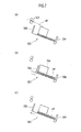
- FIGS. 8(a) to 8(c) are respectively schematic side views for each process explaining a preparatory operation of receiving the pre-folded sheet in the present embodiment.
- FIGS. 9(a) to 9(d) are respectively schematic side views for each process explaining the alignment operation of the pre-folded sheet in the present embodiment.
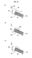
- FIGS. 10(a) to 10(c) are respectively schematic side views for each process explaining the alignment operation of text sheets after the pre-folded sheet is aligned in the present embodiment.
- FIGS. 7 to 10(b) a side guide on the front side is omitted to facilitate explanation.
- FIGS. 11(a) to 11(d) are respectively perspective views of each process of bookbinding in the present embodiment.
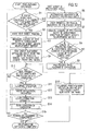
- FIG. 12 is a control flow diagram of the bookbinding system 100 of the present embodiment.
- the bookbinding system 100 includes an image forming device 200 which performs printing on a front cover sheet FP and text sheets HP, a folding device 264 provided at a position on the downstream end side in the sheet conveyance direction adjacent to the image forming device 200 to fold sheets, and a bookbinding device (case binding device) 300 provided at a position on the downstream end side of the folding device 264 in the sheet conveyance direction to perform a binding process on the printed front cover sheet FP and the printed text sheets HP.
- an image forming device 200 which performs printing on a front cover sheet FP and text sheets HP
- a folding device 264 provided at a position on the downstream end side in the sheet conveyance direction adjacent to the image forming device 200 to fold sheets
- a bookbinding device (case binding device) 300 provided at a position on the downstream end side of the folding device 264 in the sheet conveyance direction to perform a binding process on the printed front cover sheet FP and the printed text sheets HP.
- the bookbinding system 100 is a system which manufactures a bound book (booklet) 440 by performing printing on the front cover sheet FP and the text sheets HP and binding process on the printed front cover sheet FP and the printed text sheets HP.
- the bound book 440 has its three side edges except for the spine side cut off by a cutting machine.
- the image forming device 200 in the bookbinding system 100 is provided with an ink-jet image forming unit 230.
- the image forming unit 230 is configured to perform printing on the front cover sheet FP and the text sheets HP based on cover image data and text image data.
- the image forming unit 230 has a plurality of line-type ink heads which respectively eject color inks of black K, cyan C, magenta M, and yellow Y.
- a first paper feeder 210 having the front cover sheets FP accommodated and stacked thereon and a second paper feeder 220 having the text sheets HP accommodated and stacked thereon are provided upstream of the image forming unit 230 in the sheet conveyance direction.
- the second paper feeder 220 having provided therein a first paper feed tray 220a, a second paper feed tray 220b, and a third paper feed tray 220c, can accommodate text sheets HP of various types and sizes of sheets. It is possible to feed and convey sheets from the first paper feeder 210 and the second paper feeder 220 to the image forming unit 230 sequentially at a predetermined timing, while handling sheets one by one with a paper feed roller (not illustrated).
- a circular conveyance path 250 is provided downstream of the image forming unit 230 in the sheet conveyance direction.
- the printed sheets are discharged via the circular conveyance path 250 to a paper ejector 262 provided further downstream.
- the sheets discharged to the paper ejector 262 are used when the bookbinding process which will be described below is not performed.
- a path switching flapper (not illustrated) is provided in the circular conveyance path 250, which allows switching between a conveyance path to the paper ejector 262 and a conveyance path to a reversing unit 240.
- a sheet conveyed to the reversing unit 240 is reversed and switch-backed so as to be conveyed to the image forming unit 230 again. Accordingly, it becomes possible to perform duplex printing on the front cover sheet FP and the text sheets HP.
- the front cover sheet FP and the text sheets HP which have been subject to one-side printing or duplex printing, are conveyed via a communication conveyer 260 provided downstream of the image forming unit 230 in the sheet conveyance direction, folded by the folding device 264 as necessary, and conveyed to the bookbinding device 300.
- the communication conveyance path 260 and the circular conveyance path 250 are provided with the path switching flapper, and the path is selected as appropriate.
- the folding device 264 is controlled by a controller 282 which will be described below so that a sheet not supposed to be folded passes therethrough as it is.
- An input panel 270 is provided at the top surface of the image forming device 200.
- the input panel 270 has provided thereon a start button for instructing execution of bookbinding, a touch panel for performing various settings such as selection of cleaning mode by which ON/OFF of cleaning operation can be selected and selection of sheet size.
- the image forming device 200 usually receives job data from a personal computer connected via a communication interface, and accepts user settings by operation signals included in the job data (not shown).
- a PC Personal Computer
- a PC Personal Computer
- the controller 282 which will be described below controls the order of printing text sheets HP and an insertion position of a manual-feed sheet MP so that they are determined according to the setting of the insertion position (front cover side or back cover side) of the pre-folded sheet or the manual-feed sheet which will be described below, which has been sent from the image forming device 200, and the setting of the side to be bounded (right-side binding or left-side binding). For example, as shown in FIG.
- the controller 282 when inserting a manual-feed sheet MP between the front cover sheet and the top page with right-side binding, the controller 282 is controlled so that images are printed in descending order from the last page in a direction facing the front of the device (forward of the device), and the printed text sheets HP are stacked face up on the alignment tray 352.
- the controller 282 When inserting a manual-feed sheet MP between the last page and the back cover sheet with right-side binding, as shown in FIG. 4 , the controller 282 is controlled so that images are printed in ascending order from the top page in a direction facing the back of the device (backward of the device), and the printed text sheets HP are stacked face down on the alignment tray 352.
- the bookbinding device 300 in the bookbinding system 100 is provided with the sheet conveyer 310 which conveys the printed cover sheet FP and the printed text sheets HP which have been sent from the communication conveyance path 260 on the side of the image forming device 200.
- the cutting unit 330 which cuts the front cover sheet FP into a suitable size is provided at a position adjacent to the sheet conveyer 310.
- the conveyance switching mechanism 338 which will described below conveys the front cover sheet FP to the cutting unit 330, where cutting operation is performed.
- the cover sheet FP and the text sheets HP are respectively conveyed to a formation unit 380 and an aligner 350, via the sheet conveyer 310.
- the sheet conveyer 310 is provided with a mechanism (not shown) which switches between the conveyance paths to the formation unit 380 and the aligner 350.
- the aligner 350 is provided with the alignment tray 352 which sequentially stacks the text sheets HP conveyed thereto.
- the alignment tray 352 is provided with a front end guide (abutting fence) 354 configured to align the position of the text sheets HP in the sheet conveyance direction, a rear end guide (rear end fence) 355 provided upstream of the front end guide 354 in the conveyance direction and movable in the conveyance direction, and a side guide (side fence) 356 configured to align the position of the text sheets HP in the width direction.
- Both the front end guide 354 and the rear end guide 355 are assumed to be movable in parallel to the sheet conveyance direction, i.e., in a direction along which the distance therebetween increases or decreases.
- the aligner 350 is provided with a rear end guide home position sensor 350b, a rear end guide movement pulse motor 350c, a feed-in roller drive pulse motor 350d, a front end guide home position sensor 350e, and a front end guide movement pulse motor 350f.
- the rear end guide home position sensor 350b detects the home position of the rear end guide 355.
- the rear end guide movement pulse motor 350c provides the rear end guide 355 with a movement force.
- the feed-in roller drive pulse motor 350d provides a feed-in roller 348 with a rotational force.
- the front end guide home position sensor 350e detects the home position of the front end guide 354.
- the front end guide movement pulse motor 350f provides the front end guide 354 with a movement force.
- the feed-in roller 348 configured to feed the text sheets HP and the manual-feed sheet MP to the alignment tray 352, is provided upstream of the alignment tray 352 in the conveyance direction.
- the peripheral velocity of the feed-in roller 348 may be set by the controller 282 which will be described below so that the velocity is different for feeding the text sheets HP and for feeding the manual-feed sheet MP.
- the bookbinding device 300 is provided with, at the upper part thereof, a manual-feed sheet insertion unit 302 for inserting the manual-feed sheet MF into the alignment tray 352.
- the manual-feed sheet insertion unit 302 has an insertion unit 304 for inserting the manual-feed sheet MP from the upper part of the device, and a guide unit 306 which guides the manual-feed sheet MP inserted into the insertion unit 304 to the upstream cf the feed-in roller 348 in the conveyance direction.
- a sheet length measurement sensor 346 (see FIG. 1 ) which measures the lengths of the text sheets HP and the manual-feed sheet MP in the conveyance direction is provided downstream of the manual-feed sheet insertion unit 302 in the conveyance direction.
- a configuration is allowed such that the manual-feed sheet MP inserted from the manual-feed sheet insertion unit 302 and being in a stand-by state may be automatically fed to the alignment tray 352 at an appropriate feed timing, or a manual operation is allowed in which the manual-feed sheet MP is inserted and immediately fed to the alignment tray 352 by the user who has been waiting for an appropriate timing.
- a manual-feed sheet insertion unit 309 having an opening/closing door 307 included in the upper part of the device housing, and an insertion guide 308 which guides the manual-feed sheet MP inserted from the opening/closing door 307 to the alignment tray 352 so that the manual-feed sheet MP is placed on the text sheets HP without passing through the feed-in roller 348.
- the bookbinding device 300 has a clamping unit 370 which clamps a sheet sheaf TP fed from the aligner 350 with clampers 372 (see FIGS. 1 and 5 ).
- the clamping unit 370 is movably provided between a receiving position where the sheet sheaf TP is received from the aligner 350 by a moving mechanism (not shown) and a binding position where the sheet sheaf TP is passed to the formation unit 380.
- the manual-feed sheet MP inserted into the alignment tray 352 forms the sheet sheaf TP together with the text sheets HP and the sheet sheaf TP is clamped by the clamping unit 370.
- the clamping unit 370 is provided with a sheet sheaf thickness detection sensor 370a, a clamp open/close home position sensor 370b, a clamp movement home position sensor 370c, a clamp traverse home position sensor 370d, a clamp open/close pulse motor 370e, a clamp movement pulse motor 370f, and a clamp traverse pulse motor 370g.
- the sheet sheaf thickness detection sensor 370a detects the thickness of the sheet sheaf TP based on a distance "d" (see FIG. 5 ) between clampers 372 when the sheet sheaf TP is clamped with the clampers 372.
- the clamp open/close home position sensor 370b detects the home position with regard to open/close of the clampers (clamp plates) 372.
- the clamp movement home position sensor 370c detects the home position when clamping the sheet sheaf TP with the clamping unit 370.
- the clamp traverse home position sensor 370d detects the home position with regard to the traverse (movement between the paste application position and the formation position) of the clamping unit 370,
- the clamp open/close pulse motor 370e provides the clampers 372 with an opening/closing force.
- the clamp movement pulse motor 370f provides the clamping unit 370 with a movement force between the position where the sheet sheaf TP on the alignment tray 352 is clamped and the home position.
- the clamp traverse pulse motor 370g provides the clamping unit 370 with a movement force between the paste application position and the formation position.
- the clamping unit 370 is controlled to clamp, with the clampers 372, the front end TPT which is the edge of the sheet sheaf TP on the front end side in the conveyance direction (downstream end side in the conveyance direction), when detecting the thickness of the sheet sheaf TP.
- the clamping unit 370 is controlled to clamp, with the clampers 372, the central part of the sheet sheaf TP in the conveyance direction, when moving the sheet sheaf TP to a subsequent process.
- the central part of the sheet sheaf TP in the conveyance direction refers to, without being limited to the intermediate position between the front end and the rear end of the sheets in the conveyance direction, a part of the sheets where the sheet sheaf TP can be moved in a clamped manner with no problem.
- a book pasting device 360 is provided near the clamping unit 370 when located at the receiving position.
- the book pasting device 360 is provided with a paste accommodating unit (paste tank) 364 which accommodates paste, and a paste application roller 362 configured to apply paste to the sheet sheaf TP.
- the paste application roller 362 is elongated and held around a horizontal rotation axis inside the paste accommodating unit 364.
- the paste adheresive agent
- the formation unit 380 is provided with a back folding plate 386 on which the front cover sheet FP conveyed from the sheet conveyer 310 is placed, and an abutment plate 388 provided below the back folding plate 386, to which the back side of the sheet sheaf TP conveyed to the binding position by the clamping unit 370 abuts through the front cover sheet FP.
- the formation unit 380 is provided with a cover position detection sensor 380a, a back folding plate home position sensor 380b, an abutment plate home position sensor 380c, a cover sheet conveying motor 380d, a back folding plate movement pulse motor 380e, and an abutment plate movement pulse motor 380f.
- the cover position detection sensor 380a detects the position of the front cover sheet FP.
- the back folding plate home position sensor 380b detects the position of the back folding plate 386.
- the abutment plate home position sensor 380c detects the home position of the abutment plate 388.
- the cover sheet conveying motor 380d provides the front cover sheet FP with a conveyance power.
- the back folding plate movement pulse motor 380e provides the back folding plate 386 with a movement force.
- the abutment plate movement pulse motor 380f provides the abutment plate 388 with a movement force.
- a bound book ejection unit 390 is configured to be able to accommodate a plurality of bound books 440 which have been bound and formed in the formation unit 380 (see FIGS. 1 and 11(d) ) and conveyed from the formation unit 380. Note that, in the present embodiment, conveyance from the formation unit 380 uses free-fall of the bound books 440,
- the sheet conveyer 310 is provided with four pieces of roller pairs in the order of a first conveyance roller 312, a second conveyance roller 314, a conveyance reference roller 316, and a conveyance reference auxiliary roller 322, from upstream of the sheet conveyance direction.
- the conveyance reference roller 316 is provided with a conveyance reference encoder 318 configured to control the amount of conveyance of the front cover sheet FP.
- a cover sheet size sensor 320 configured to detect the length of the front cover sheet FP in the conveyance direction is provided between the conveyance reference roller 316 and the conveyance reference auxiliary roller 322.
- the conveyance switching mechanism 338 is provided between the first conveyance roller 312 and the second conveyance roller 314.
- the conveyance switching mechanism 338 is capable of switching between two paths, i.e., a normal conveyance path 338a which allows conveyance between the first conveyance roller 312 and the second conveyance roller 314, and a cutting conveyance path 338b which allows conveyance between the second conveyance roller 314 and the cutting unit 330, by pivoting around a switching fulcrum 338c using a drive mechanism (not shown).
- the cutting unit 330 is provided with a cut auxiliary roller 336, a cutter 334, and a scrap container 332, in this order from the position near the conveyance path switching mechanism 338.
- the cutter 334 is a shuttle cutter, which can perform cutting with its blade moving back and forth in the width direction of the front cover sheet FP.
- the cut auxiliary roller 336 holds the front cover sheet FP when the cutter 334 cuts the front cover sheet FP.
- the scrap container 332 is configured to be able to accommodate useless parts of the cover sheet which becomes useless when cut.
- the scrap container 332 is removably provided so that the user can dispose of useless parts of the cover sheet accommodated therein to outside the container.
- the cutting unit 330 is provided with a cutter home position sensor 330a, and a cutter motor 330b connected to the cutter home position sensor 330a.
- the controller 282 uses the cutter home position sensor 330a, the controller 282 adjusts the home position of the cutter motor 330b having the cutter 334 (see FIG. 2 ) attached thereto, so that the length of the front cover sheet FP in the conveyance direction becomes appropriate.
- the bookbinding system 100 is provided with the controller 282.
- the controller 282 controls each part of the image forming device 200 and the bookbinding device 300, based on input information from the input panel 270, the conveyance reference encoder 318 (see FIG. 2 ), the cover sheet size sensor 320, or the like.
- the controller 282 has a memory unit 284 configured to store the sheet size or the like, a page printing order determination unit 285 configured to determine the order of pages to be printed, and an image direction determination unit 286 configured to determine the direction of images when printing. Furthermore, the controller 282 has a cover sheet appropriate dimension calculator 287 configured to calculate an appropriate length of the front cover sheet FP in the conveyance direction, and a manual-feed sheet insertion unit controller 288 configured to insert the manual-feed sheet MP at a predetermined timing. In the present embodiment, a cutting position determination unit 287k is configured to cut the front cover sheet FP into a predetermined length based on the length calculated by the cover sheet appropriate dimension calculator 287. The controller 282 also has an aligner controller 289 configured to control the drive operation of the front end guide movement pulse motor 350f and the rear end guide movement pulse motor 350c.
- the controller 282 has a clamp unit controller 296 configured to control the clamping unit 370, and a sheet sheaf thickness detector 299 configured to detect the thickness of the front end TPT by clamping (pre-clamping) the front end TPT of the sheet sheaf TP with the clamping unit 370.
- the front end TPT is an edge forming the spine side when the book is bound.
- the clamp unit controller 296 has a pre-clamp position calculator 297 configured to calculate the pre-clamp position to detect the thickness, and a clamp position calculator 298 configured to calculate the clamping position when conveying the sheet sheaf TP.
- the controller 282 has a pasting device controller 290 configured to control the drive of the book passing device 360.
- the pasting device controller 290 controls the book pasting device 360 so as to rotate the paste application roller 362 and stop it at an application position and, after the application of paste to the spine side of the text sheets HP is completed, rotate the paste application roller 362 and stop it at a wait position.
- the controller 282 has a timer 291.
- the timer 291 receives a signal from the cover position detection sensor 380a described above, and controls the formation unit 380 so that the text sheets HP and the front cover sheets FP are appropriately formed in the formation unit 380.
- the pre-folded sheet ZP will be described as it printed by the image forming device 200 and folded by the folding device 264.
- the bookbinding system 100 determines, as will be described below, that a manual-feed sheet MP inserted from the manual-feed sheet insertion unit 302 is a pre-folded sheet ZP and processes it accordingly.
- pre-folded sheet refers to a pre-folded sheet before being folded or after having been folded by the folding device 264 and, when the phrase "printing of a pre-folded sheet” is described, it means that the image forming device 200 preliminarily performs printing on a sheet to be folded.
- the controller 282 determines whether or not the next sheet to be conveyed from the image forming device 200 to the alignment tray 352 is a text sheet HP other than a pre-folded sheet ZP (step S1).
- step S2 If the sheet to be conveyed is a text sheet HP other than a pre-folded sheet ZP (YES), printing of the text sheet HP is started (step S2). Subsequently, the length of the text sheet HP in the conveyance direction is measured by the sheet length measurement sensor 346 (step S3), and an alignment operation of the text sheets HP placed in the alignment tray 352 is performed (step S4). At step S4, as shown in FIGS. 7(a) to 7(c) and FIGS.
- alignment is performed by moving the rear end guide 355 downstream of the conveyance direction (toward the front end guide 354) back to its original position each time a text sheet HP is discharged to the alignment tray 352 by the feed-in roller 348, and causing the front end of the text sheets HP in the conveyance direction to abut against the front end guide 354.
- the distance of movement of the rear end guide 355 is determined by calculating an appropriate value by the controller 282, based on the length measured at step S3.
- step S5 the preparatory operation of receiving the pre-folded sheet ZP is performed (step S5).
- step S5 as shown in FIGS. 8(a) to 8(c) , the front end guide 354 is moved from the home position to the upstream of the conveyance direction (toward the rear end guide 355), and the sheaf of the text sheets HP accommodated in the alignment tray 352 is moved toward the rear end guide 355. Subsequently, the front end guide 354 is returned to the home position which is its original position.
- the home position of the front end guide 354 is a position when receiving the text sheets HP other than the pre-folded sheet ZP in the alignment tray 352, as shown in FIGS. 8(a) and 8(c) .
- step S6 the image forming device 200 performs printing on a pre-folded sheet ZP and the pre-folded sheet ZP is conveyed from the folding device 264 to the bookbinding device 300, or a pre-folded sheet ZP is inserted from the manual-feed sheet insertion unit 302 (step S6), and the length of the pre-folded sheet ZP in the conveyance direction is measured by the sheet length measurement sensor 346 (step S7). It is then determined (step S8) whether or not the length of pre-folded sheet ZP in the conveyance direction is shorter than a prescribed length B (see FIG. 14 ) from the spine side to the page opening side of the text sheets HP of a bound book 444 (see FIG. 15 ) which has been discharged from the bookbinding system 100 and has its side edges cut off.
- a prescribed length B see FIG. 14
- step S9 the alignment operation of the pre-folded sheet ZP is performed (step S9).
- step S9 as shown in FIGS. 9(a) to 9(d) , discharging the pre-folded sheet ZP to the alignment tray 352 by the feed-in roller 348 positions the front end of pre-folded sheet ZP in the conveyance direction further downstream of the conveyance direction than the front end of the text sheets HP in the conveyance direction (see FIG. 9(b) ).
- Moving the rear end guide 355 downstream, of the conveyance direction causes the front end position of the text sheets HP and the pre-folded sheet ZP in the conveyance direction to abut against the front end guide 354, thereby aligning the sheets (see FIG. 9(c) ). Subsequently, the rear end guide 355 is returned to its original position (see FIG. 9(d) ). As a result, the front ends of the sheets are precisely aligned.
- the bookbinding system 100 determines that a sheet inserted from the manual-feed sheet insertion unit 302 is a pre-folded sheet ZP, and thus steps S5 to S9 are performed without performing steps S1 to S4.
- step S9 it is determined whether or not printing of the text sheets HP and the pre-folded sheet ZP has been completed (step S10). If printing has not been completed (NO), the process flow returns to step S1.
- step S10 If printing has been completed at step S10 (YES), the sheet sheaf TP in the alignment tray 352 is clamped by the clamping unit 370 (step S11), and paste is applied to the spine side of the clamped sheet sheaf TP by the book pasting device 360 (step S12). A cover formation operation is then performed (see FIG. 11 , step S13), and a book conveyance operation is performed to discharge the bound book 440 manufactured by the bookbinding system 100 to the bound book ejection unit 390 (step S14).
- step S15 it is determined whether or not all the scheduled bookbinding operations have been completed. If not all the bookbinding operations have been completed (NO), the process flow returns to step S1. If all the bookbinding operations have been completed (YES), the print-and-bind operation is terminated.
- the print-and-bind operation is interrupted and a message "pre-folded sheet size over" is displayed on the input panel 270 (step S16).
- the message may be communicated to the user via a sound such as an alarm instead of displaying it.
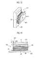
- FIG. 13 is a perspective view showing how the bound book 440 is clamped by a clamping mechanism 470 of the cutting machine.
- FIG. 14 is a side view showing how the side edge of the bound book 440 is cut off by the cutting machine.
- FIG. 15 is a plan view explaining how a finished book is obtained by cutting off the side edges of the bound book 440 by the cutting machine.
- the bound book 440 discharged at step S14 (before subject to cutting into a finished book) subsequently has its three side edges 440p, 440q and 440r except for the spine side cut off by the cutting machine into a finished book 444, as shown in FIGS. 13 to 15 .
- the bound book 440 is clamped by the clamping mechanism 470 of the cutting machine, and each side edge except for the spine side is cut off by a cutter 472 of the cutting machine.
- the cutting is performed so that the text sheets HP and the front cover sheet FP conform with the standard size at the time of bookbinding.
- the bookbinding operation is interrupted by the controller 282 if the length of the pre-folded sheet ZP in the conveyance direction is not equal to or less than the prescribed length B from the spine side to the page opening side of the text sheets HP in the bound book 444 having its side edges 440p, 440q and 440r cut off. Therefore, as shown in FIG. 14 , the pre-folded sheet ZP will never protrude beyond the text sheets HP at the page opening side US of the bound book 440 opposite to the spine side BS. Therefore, the folded part ZPB of pre-folded sheet ZP will never be cut off even if the page opening side US of the bound book 440 is cut off by the cutting machine.
- the front end position of the text sheets HP and the pre-folded sheet ZP in the conveyance direction can be aligned by controlling the movement of the rear end guide 355 and the front end guide 354 as discussed above. Therefore, the mechanism can be simplified without using a rotating paddle, and also prevention of the folded part ZPB of the pre-folded sheet ZP from being cut off can be easily realized without requiring a special device or a special operation procedure.
- insertion of the pre-folded sheet ZP is not particularly limited to the last page or the like, and it can be inserted midway through stacking of the text sheets HP.
Landscapes
- Engineering & Computer Science (AREA)
- Mechanical Engineering (AREA)
- Folding Of Thin Sheet-Like Materials, Special Discharging Devices, And Others (AREA)
- Counters In Electrophotography And Two-Sided Copying (AREA)
- Paper Feeding For Electrophotography (AREA)
- Pile Receivers (AREA)
Applications Claiming Priority (1)
| Application Number | Priority Date | Filing Date | Title |
|---|---|---|---|
| JP2012018750A JP5860708B2 (ja) | 2012-01-31 | 2012-01-31 | 製本システム |
Publications (3)
| Publication Number | Publication Date |
|---|---|
| EP2623451A2 true EP2623451A2 (de) | 2013-08-07 |
| EP2623451A3 EP2623451A3 (de) | 2017-03-15 |
| EP2623451B1 EP2623451B1 (de) | 2018-10-31 |
Family
ID=47683590
Family Applications (1)
| Application Number | Title | Priority Date | Filing Date |
|---|---|---|---|
| EP13153442.2A Not-in-force EP2623451B1 (de) | 2012-01-31 | 2013-01-31 | Buchbindesystem |
Country Status (2)
| Country | Link |
|---|---|
| EP (1) | EP2623451B1 (de) |
| JP (1) | JP5860708B2 (de) |
Cited By (1)
| Publication number | Priority date | Publication date | Assignee | Title |
|---|---|---|---|---|
| US20210178623A1 (en) * | 2018-04-20 | 2021-06-17 | Canon Finetech Nisca Inc. | Sheet bundle cutting apparatus and bookbinding apparatus |
Families Citing this family (1)
| Publication number | Priority date | Publication date | Assignee | Title |
|---|---|---|---|---|
| JP6388800B2 (ja) * | 2014-06-30 | 2018-09-12 | 理想科学工業株式会社 | 製本装置 |
Citations (1)
| Publication number | Priority date | Publication date | Assignee | Title |
|---|---|---|---|---|
| JP2009029562A (ja) | 2007-07-26 | 2009-02-12 | Nisca Corp | 製本装置及びこれを備えた画像形成システム |
Family Cites Families (9)
| Publication number | Priority date | Publication date | Assignee | Title |
|---|---|---|---|---|
| JPH07172672A (ja) * | 1993-12-21 | 1995-07-11 | Canon Inc | シート整合装置 |
| JP2005306505A (ja) * | 2004-04-16 | 2005-11-04 | Canon Finetech Inc | シート処理装置及びこれを備えた画像形成装置 |
| JP2007302377A (ja) * | 2006-05-09 | 2007-11-22 | Canon Inc | シート処理装置及び画像形成装置 |
| JP4743777B2 (ja) * | 2006-06-30 | 2011-08-10 | 京セラミタ株式会社 | シート排出装置 |
| JP2008074012A (ja) * | 2006-09-22 | 2008-04-03 | Canon Finetech Inc | 製本装置及びこれを備えた画像形成システム |
| JP4964646B2 (ja) * | 2007-03-29 | 2012-07-04 | ニスカ株式会社 | 製本装置及びこれを備えた画像形成システム |
| JP2008247598A (ja) * | 2007-03-30 | 2008-10-16 | Ricoh Elemex Corp | 用紙後処理装置 |
| US8226079B2 (en) * | 2009-08-04 | 2012-07-24 | Kabushiki Kaisha Toshiba | Manual stapling mode for sheet finishing apparatus |
| US8246034B2 (en) * | 2009-09-15 | 2012-08-21 | Kabushiki Kaisha Toshiba | Sheet processing apparatus and a sheet processing method |
-
2012
- 2012-01-31 JP JP2012018750A patent/JP5860708B2/ja not_active Expired - Fee Related
-
2013
- 2013-01-31 EP EP13153442.2A patent/EP2623451B1/de not_active Not-in-force
Patent Citations (1)
| Publication number | Priority date | Publication date | Assignee | Title |
|---|---|---|---|---|
| JP2009029562A (ja) | 2007-07-26 | 2009-02-12 | Nisca Corp | 製本装置及びこれを備えた画像形成システム |
Cited By (1)
| Publication number | Priority date | Publication date | Assignee | Title |
|---|---|---|---|---|
| US20210178623A1 (en) * | 2018-04-20 | 2021-06-17 | Canon Finetech Nisca Inc. | Sheet bundle cutting apparatus and bookbinding apparatus |
Also Published As
| Publication number | Publication date |
|---|---|
| JP2013155033A (ja) | 2013-08-15 |
| EP2623451B1 (de) | 2018-10-31 |
| JP5860708B2 (ja) | 2016-02-16 |
| EP2623451A3 (de) | 2017-03-15 |
Similar Documents
| Publication | Publication Date | Title |
|---|---|---|
| CN100577544C (zh) | 片材处理设备、片材处理方法和成像系统 | |
| JP5950132B2 (ja) | 画像形成システム | |
| JP2010241108A (ja) | 製本装置、及び製本システム | |
| JP2005041658A (ja) | 用紙折り装置、用紙折り方法及び後処理装置 | |
| EP2623451B1 (de) | Buchbindesystem | |
| JP6146881B2 (ja) | 中綴じ折り装置 | |
| US20090152787A1 (en) | Sheet stacking apparatus, image forming system, and image forming apparatus | |
| JP4609246B2 (ja) | 製本システム、画像形成装置及び製本装置 | |
| JP3927717B2 (ja) | 用紙後処理装置 | |
| JP5827877B2 (ja) | 製本システム | |
| US8262073B2 (en) | Sheet processing apparatus | |
| JP7075210B2 (ja) | シート処理装置及びこれを備える画像形成システム | |
| US20070003346A1 (en) | Bookmaking apparatus and image forming apparatus equipped with the same | |
| US7905477B2 (en) | Intermediate conveying apparatus | |
| JP2014141022A (ja) | 製本装置 | |
| US20070009298A1 (en) | Sheet bundle conveyance apparatus and bookmaking apparatus | |
| JP5997435B2 (ja) | 製本システム | |
| JP2006027818A (ja) | 用紙処理装置 | |
| JP4123095B2 (ja) | 後処理装置 | |
| US8800989B2 (en) | Paper conveying device | |
| JP4478979B2 (ja) | テープ供給装置及びその制御方法 | |
| EP2506080B1 (de) | Bilderzeugungssystem | |
| JP2004277069A (ja) | 画像処理方法、画像処理システム、およびシート後処理装置 | |
| JP2010115885A (ja) | 製本装置および製本方法並びに画像形成システム | |
| JP4689443B2 (ja) | 被記録媒体後処理装置及び画像形成装置 |
Legal Events
| Date | Code | Title | Description |
|---|---|---|---|
| PUAI | Public reference made under article 153(3) epc to a published international application that has entered the european phase |
Free format text: ORIGINAL CODE: 0009012 |
|
| 17P | Request for examination filed |
Effective date: 20130131 |
|
| AK | Designated contracting states |
Kind code of ref document: A2 Designated state(s): AL AT BE BG CH CY CZ DE DK EE ES FI FR GB GR HR HU IE IS IT LI LT LU LV MC MK MT NL NO PL PT RO RS SE SI SK SM TR |
|
| AX | Request for extension of the european patent |
Extension state: BA ME |
|
| RIN1 | Information on inventor provided before grant (corrected) |
Inventor name: IIDA, KOUJCHIRO C/O RISO KAGAKU CORPORATION / R&D Inventor name: HIROSHIMA, ATSUSHI C/O RISO KAGAKU CORPORATION / R |
|
| PUAL | Search report despatched |
Free format text: ORIGINAL CODE: 0009013 |
|
| AK | Designated contracting states |
Kind code of ref document: A3 Designated state(s): AL AT BE BG CH CY CZ DE DK EE ES FI FR GB GR HR HU IE IS IT LI LT LU LV MC MK MT NL NO PL PT RO RS SE SI SK SM TR |
|
| AX | Request for extension of the european patent |
Extension state: BA ME |
|
| RIC1 | Information provided on ipc code assigned before grant |
Ipc: B42C 19/02 20060101ALI20170208BHEP Ipc: B42C 1/12 20060101ALI20170208BHEP Ipc: B42C 11/04 20060101ALI20170208BHEP Ipc: B65H 31/38 20060101AFI20170208BHEP |
|
| STAA | Information on the status of an ep patent application or granted ep patent |
Free format text: STATUS: EXAMINATION IS IN PROGRESS |
|
| 17Q | First examination report despatched |
Effective date: 20180122 |
|
| GRAP | Despatch of communication of intention to grant a patent |
Free format text: ORIGINAL CODE: EPIDOSNIGR1 |
|
| STAA | Information on the status of an ep patent application or granted ep patent |
Free format text: STATUS: GRANT OF PATENT IS INTENDED |
|
| INTG | Intention to grant announced |
Effective date: 20180711 |
|
| GRAS | Grant fee paid |
Free format text: ORIGINAL CODE: EPIDOSNIGR3 |
|
| GRAA | (expected) grant |
Free format text: ORIGINAL CODE: 0009210 |
|
| STAA | Information on the status of an ep patent application or granted ep patent |
Free format text: STATUS: THE PATENT HAS BEEN GRANTED |
|
| AK | Designated contracting states |
Kind code of ref document: B1 Designated state(s): AL AT BE BG CH CY CZ DE DK EE ES FI FR GB GR HR HU IE IS IT LI LT LU LV MC MK MT NL NO PL PT RO RS SE SI SK SM TR |
|
| REG | Reference to a national code |
Ref country code: CH Ref legal event code: EP Ref country code: GB Ref legal event code: FG4D |
|
| RIN1 | Information on inventor provided before grant (corrected) |
Inventor name: IIDA, KOUICHIRO C/O RISO KAGAKU CORPORATION R&D CE Inventor name: HIROSHIMA, ATSUSHI C/O RISO KAGAKU CORPORATION / R |
|
| REG | Reference to a national code |
Ref country code: AT Ref legal event code: REF Ref document number: 1059117 Country of ref document: AT Kind code of ref document: T Effective date: 20181115 |
|
| REG | Reference to a national code |
Ref country code: IE Ref legal event code: FG4D |
|
| REG | Reference to a national code |
Ref country code: DE Ref legal event code: R096 Ref document number: 602013045810 Country of ref document: DE |
|
| REG | Reference to a national code |
Ref country code: NL Ref legal event code: MP Effective date: 20181031 |
|
| REG | Reference to a national code |
Ref country code: LT Ref legal event code: MG4D |
|
| REG | Reference to a national code |
Ref country code: AT Ref legal event code: MK05 Ref document number: 1059117 Country of ref document: AT Kind code of ref document: T Effective date: 20181031 |
|
| PG25 | Lapsed in a contracting state [announced via postgrant information from national office to epo] |
Ref country code: FI Free format text: LAPSE BECAUSE OF FAILURE TO SUBMIT A TRANSLATION OF THE DESCRIPTION OR TO PAY THE FEE WITHIN THE PRESCRIBED TIME-LIMIT Effective date: 20181031 Ref country code: BG Free format text: LAPSE BECAUSE OF FAILURE TO SUBMIT A TRANSLATION OF THE DESCRIPTION OR TO PAY THE FEE WITHIN THE PRESCRIBED TIME-LIMIT Effective date: 20190131 Ref country code: PL Free format text: LAPSE BECAUSE OF FAILURE TO SUBMIT A TRANSLATION OF THE DESCRIPTION OR TO PAY THE FEE WITHIN THE PRESCRIBED TIME-LIMIT Effective date: 20181031 Ref country code: HR Free format text: LAPSE BECAUSE OF FAILURE TO SUBMIT A TRANSLATION OF THE DESCRIPTION OR TO PAY THE FEE WITHIN THE PRESCRIBED TIME-LIMIT Effective date: 20181031 Ref country code: LV Free format text: LAPSE BECAUSE OF FAILURE TO SUBMIT A TRANSLATION OF THE DESCRIPTION OR TO PAY THE FEE WITHIN THE PRESCRIBED TIME-LIMIT Effective date: 20181031 Ref country code: IS Free format text: LAPSE BECAUSE OF FAILURE TO SUBMIT A TRANSLATION OF THE DESCRIPTION OR TO PAY THE FEE WITHIN THE PRESCRIBED TIME-LIMIT Effective date: 20190228 Ref country code: ES Free format text: LAPSE BECAUSE OF FAILURE TO SUBMIT A TRANSLATION OF THE DESCRIPTION OR TO PAY THE FEE WITHIN THE PRESCRIBED TIME-LIMIT Effective date: 20181031 Ref country code: AT Free format text: LAPSE BECAUSE OF FAILURE TO SUBMIT A TRANSLATION OF THE DESCRIPTION OR TO PAY THE FEE WITHIN THE PRESCRIBED TIME-LIMIT Effective date: 20181031 Ref country code: LT Free format text: LAPSE BECAUSE OF FAILURE TO SUBMIT A TRANSLATION OF THE DESCRIPTION OR TO PAY THE FEE WITHIN THE PRESCRIBED TIME-LIMIT Effective date: 20181031 Ref country code: NO Free format text: LAPSE BECAUSE OF FAILURE TO SUBMIT A TRANSLATION OF THE DESCRIPTION OR TO PAY THE FEE WITHIN THE PRESCRIBED TIME-LIMIT Effective date: 20190131 |
|
| PG25 | Lapsed in a contracting state [announced via postgrant information from national office to epo] |
Ref country code: NL Free format text: LAPSE BECAUSE OF FAILURE TO SUBMIT A TRANSLATION OF THE DESCRIPTION OR TO PAY THE FEE WITHIN THE PRESCRIBED TIME-LIMIT Effective date: 20181031 Ref country code: RS Free format text: LAPSE BECAUSE OF FAILURE TO SUBMIT A TRANSLATION OF THE DESCRIPTION OR TO PAY THE FEE WITHIN THE PRESCRIBED TIME-LIMIT Effective date: 20181031 Ref country code: PT Free format text: LAPSE BECAUSE OF FAILURE TO SUBMIT A TRANSLATION OF THE DESCRIPTION OR TO PAY THE FEE WITHIN THE PRESCRIBED TIME-LIMIT Effective date: 20190301 Ref country code: AL Free format text: LAPSE BECAUSE OF FAILURE TO SUBMIT A TRANSLATION OF THE DESCRIPTION OR TO PAY THE FEE WITHIN THE PRESCRIBED TIME-LIMIT Effective date: 20181031 Ref country code: GR Free format text: LAPSE BECAUSE OF FAILURE TO SUBMIT A TRANSLATION OF THE DESCRIPTION OR TO PAY THE FEE WITHIN THE PRESCRIBED TIME-LIMIT Effective date: 20190201 Ref country code: SE Free format text: LAPSE BECAUSE OF FAILURE TO SUBMIT A TRANSLATION OF THE DESCRIPTION OR TO PAY THE FEE WITHIN THE PRESCRIBED TIME-LIMIT Effective date: 20181031 |
|
| PG25 | Lapsed in a contracting state [announced via postgrant information from national office to epo] |
Ref country code: IT Free format text: LAPSE BECAUSE OF FAILURE TO SUBMIT A TRANSLATION OF THE DESCRIPTION OR TO PAY THE FEE WITHIN THE PRESCRIBED TIME-LIMIT Effective date: 20181031 Ref country code: CZ Free format text: LAPSE BECAUSE OF FAILURE TO SUBMIT A TRANSLATION OF THE DESCRIPTION OR TO PAY THE FEE WITHIN THE PRESCRIBED TIME-LIMIT Effective date: 20181031 Ref country code: DK Free format text: LAPSE BECAUSE OF FAILURE TO SUBMIT A TRANSLATION OF THE DESCRIPTION OR TO PAY THE FEE WITHIN THE PRESCRIBED TIME-LIMIT Effective date: 20181031 |
|
| REG | Reference to a national code |
Ref country code: DE Ref legal event code: R097 Ref document number: 602013045810 Country of ref document: DE |
|
| PG25 | Lapsed in a contracting state [announced via postgrant information from national office to epo] |
Ref country code: EE Free format text: LAPSE BECAUSE OF FAILURE TO SUBMIT A TRANSLATION OF THE DESCRIPTION OR TO PAY THE FEE WITHIN THE PRESCRIBED TIME-LIMIT Effective date: 20181031 Ref country code: SM Free format text: LAPSE BECAUSE OF FAILURE TO SUBMIT A TRANSLATION OF THE DESCRIPTION OR TO PAY THE FEE WITHIN THE PRESCRIBED TIME-LIMIT Effective date: 20181031 Ref country code: MC Free format text: LAPSE BECAUSE OF FAILURE TO SUBMIT A TRANSLATION OF THE DESCRIPTION OR TO PAY THE FEE WITHIN THE PRESCRIBED TIME-LIMIT Effective date: 20181031 Ref country code: SK Free format text: LAPSE BECAUSE OF FAILURE TO SUBMIT A TRANSLATION OF THE DESCRIPTION OR TO PAY THE FEE WITHIN THE PRESCRIBED TIME-LIMIT Effective date: 20181031 Ref country code: RO Free format text: LAPSE BECAUSE OF FAILURE TO SUBMIT A TRANSLATION OF THE DESCRIPTION OR TO PAY THE FEE WITHIN THE PRESCRIBED TIME-LIMIT Effective date: 20181031 |
|
| REG | Reference to a national code |
Ref country code: CH Ref legal event code: PL |
|
| PLBE | No opposition filed within time limit |
Free format text: ORIGINAL CODE: 0009261 |
|
| STAA | Information on the status of an ep patent application or granted ep patent |
Free format text: STATUS: NO OPPOSITION FILED WITHIN TIME LIMIT |
|
| PG25 | Lapsed in a contracting state [announced via postgrant information from national office to epo] |
Ref country code: LU Free format text: LAPSE BECAUSE OF NON-PAYMENT OF DUE FEES Effective date: 20190131 |
|
| 26N | No opposition filed |
Effective date: 20190801 |
|
| REG | Reference to a national code |
Ref country code: BE Ref legal event code: MM Effective date: 20190131 |
|
| REG | Reference to a national code |
Ref country code: IE Ref legal event code: MM4A |
|
| PG25 | Lapsed in a contracting state [announced via postgrant information from national office to epo] |
Ref country code: SI Free format text: LAPSE BECAUSE OF FAILURE TO SUBMIT A TRANSLATION OF THE DESCRIPTION OR TO PAY THE FEE WITHIN THE PRESCRIBED TIME-LIMIT Effective date: 20181031 |
|
| PG25 | Lapsed in a contracting state [announced via postgrant information from national office to epo] |
Ref country code: BE Free format text: LAPSE BECAUSE OF NON-PAYMENT OF DUE FEES Effective date: 20190131 |
|
| PG25 | Lapsed in a contracting state [announced via postgrant information from national office to epo] |
Ref country code: CH Free format text: LAPSE BECAUSE OF NON-PAYMENT OF DUE FEES Effective date: 20190131 Ref country code: LI Free format text: LAPSE BECAUSE OF NON-PAYMENT OF DUE FEES Effective date: 20190131 |
|
| PG25 | Lapsed in a contracting state [announced via postgrant information from national office to epo] |
Ref country code: IE Free format text: LAPSE BECAUSE OF NON-PAYMENT OF DUE FEES Effective date: 20190131 |
|
| PG25 | Lapsed in a contracting state [announced via postgrant information from national office to epo] |
Ref country code: TR Free format text: LAPSE BECAUSE OF FAILURE TO SUBMIT A TRANSLATION OF THE DESCRIPTION OR TO PAY THE FEE WITHIN THE PRESCRIBED TIME-LIMIT Effective date: 20181031 |
|
| PG25 | Lapsed in a contracting state [announced via postgrant information from national office to epo] |
Ref country code: MT Free format text: LAPSE BECAUSE OF NON-PAYMENT OF DUE FEES Effective date: 20190131 |
|
| PGFP | Annual fee paid to national office [announced via postgrant information from national office to epo] |
Ref country code: FR Payment date: 20210126 Year of fee payment: 9 |
|
| PG25 | Lapsed in a contracting state [announced via postgrant information from national office to epo] |
Ref country code: CY Free format text: LAPSE BECAUSE OF FAILURE TO SUBMIT A TRANSLATION OF THE DESCRIPTION OR TO PAY THE FEE WITHIN THE PRESCRIBED TIME-LIMIT Effective date: 20181031 |
|
| PGFP | Annual fee paid to national office [announced via postgrant information from national office to epo] |
Ref country code: GB Payment date: 20210127 Year of fee payment: 9 Ref country code: DE Payment date: 20210120 Year of fee payment: 9 |
|
| PG25 | Lapsed in a contracting state [announced via postgrant information from national office to epo] |
Ref country code: HU Free format text: LAPSE BECAUSE OF FAILURE TO SUBMIT A TRANSLATION OF THE DESCRIPTION OR TO PAY THE FEE WITHIN THE PRESCRIBED TIME-LIMIT; INVALID AB INITIO Effective date: 20130131 |
|
| PG25 | Lapsed in a contracting state [announced via postgrant information from national office to epo] |
Ref country code: MK Free format text: LAPSE BECAUSE OF FAILURE TO SUBMIT A TRANSLATION OF THE DESCRIPTION OR TO PAY THE FEE WITHIN THE PRESCRIBED TIME-LIMIT Effective date: 20181031 |
|
| REG | Reference to a national code |
Ref country code: DE Ref legal event code: R119 Ref document number: 602013045810 Country of ref document: DE |
|
| GBPC | Gb: european patent ceased through non-payment of renewal fee |
Effective date: 20220131 |
|
| PG25 | Lapsed in a contracting state [announced via postgrant information from national office to epo] |
Ref country code: GB Free format text: LAPSE BECAUSE OF NON-PAYMENT OF DUE FEES Effective date: 20220131 Ref country code: DE Free format text: LAPSE BECAUSE OF NON-PAYMENT OF DUE FEES Effective date: 20220802 |
|
| PG25 | Lapsed in a contracting state [announced via postgrant information from national office to epo] |
Ref country code: FR Free format text: LAPSE BECAUSE OF NON-PAYMENT OF DUE FEES Effective date: 20220131 |