EP2620573A2 - Agencement de tige de verrouillage, notamment sur une fermeture d'armoire - Google Patents
Agencement de tige de verrouillage, notamment sur une fermeture d'armoire Download PDFInfo
- Publication number
- EP2620573A2 EP2620573A2 EP13152310.2A EP13152310A EP2620573A2 EP 2620573 A2 EP2620573 A2 EP 2620573A2 EP 13152310 A EP13152310 A EP 13152310A EP 2620573 A2 EP2620573 A2 EP 2620573A2
- Authority
- EP
- European Patent Office
- Prior art keywords
- bearing
- locking bar
- head
- bearing opening
- projections
- Prior art date
- Legal status (The legal status is an assumption and is not a legal conclusion. Google has not performed a legal analysis and makes no representation as to the accuracy of the status listed.)
- Granted
Links
Images




Classifications
-
- E—FIXED CONSTRUCTIONS
- E05—LOCKS; KEYS; WINDOW OR DOOR FITTINGS; SAFES
- E05C—BOLTS OR FASTENING DEVICES FOR WINGS, SPECIALLY FOR DOORS OR WINDOWS
- E05C9/00—Arrangements of simultaneously actuated bolts or other securing devices at well-separated positions on the same wing
- E05C9/20—Coupling means for sliding bars, rods, or cables
-
- E—FIXED CONSTRUCTIONS
- E05—LOCKS; KEYS; WINDOW OR DOOR FITTINGS; SAFES
- E05C—BOLTS OR FASTENING DEVICES FOR WINGS, SPECIALLY FOR DOORS OR WINDOWS
- E05C9/00—Arrangements of simultaneously actuated bolts or other securing devices at well-separated positions on the same wing
- E05C9/04—Arrangements of simultaneously actuated bolts or other securing devices at well-separated positions on the same wing with two sliding bars moved in opposite directions when fastening or unfastening
- E05C9/043—Arrangements of simultaneously actuated bolts or other securing devices at well-separated positions on the same wing with two sliding bars moved in opposite directions when fastening or unfastening with crank pins and connecting rods
Definitions
- the invention relates to a locking bar assembly, in particular a cabinet closure with at least one by turning a drive lever between a locking position and an unlocking back and forth displaceable locking bar, the at least one locking bar has a bolt head and a hinge portion, and rotatably attached to the Anlenkabêt on an arm of the lever is, wherein a bearing pin engages through a bearing opening and is at least inhibited against escaping from the bearing opening, for example.
- a locking bar arrangement of the aforementioned type is known from the DE 66 06 725 U ,
- a two-armed drive lever carries at its two ends driving pins, which are each coupled to a locking bar.
- the drive lever sits on a shaft, which can be turned by a pusher.
- the driving pins have circumferential grooves, into which securing rings can be inserted, in order to tie the articulation sections of the locking rods to the bearing journals in a form-fitting manner.
- the invention has for its object to improve a locking bar assembly assembly technology.
- the bearing opening and the bearing journal are initially connected to each other via a clip connection.
- the bearing pin can sit firmly on the drive lever.
- the bearing opening may be formed by the Anlenkabsacrificing the locking bar.
- the journal can form a head with its free end, followed by a reduced cross-neck neck.
- the bearing opening can be at least partially made so with respect to the head with undersize and with respect to the neck with excess that the bearing opening can only be plugged by overcoming an axial force on the head on the journal. It is then freely rotatable around the neck.
- either the bearing opening or the edge of the head can have a ramp.
- both the edge of the head and the bearing opening each have a ramp, which slide off each other when plugging.
- the transition section between the head and neck of the journal may be stepped.
- the step can form a slope, which has a smaller pitch relative to the plane of rotation than the ramps.
- the axial force to be overcome when connecting the bearing opening and the bearing journal is less than an opposite axial force, which must be overcome for separating bearing journal and bearing opening.
- the bearing opening has recesses adapted to the projections. According to this embodiment, the bearing opening can be connected only in certain assembly rotational positions with the journal.
- the projections can dive through the recesses adapted to them when attaching the bearing opening.
- the bearing pin is positively held in the bearing opening.
- the projections and the recesses are arranged such that the projections do not pass over the recesses in the intended use of the locking bar assembly, so when shifting back and forth the locking bars.
- the journal is then constantly locked in a form-fitting manner in the bearing opening.
- the cross-section reduced neck can form a cone surface. At this conical surface can follow a pointing away from the head shaft, which is made with excess over the bearing opening.
- the bearing opening need not be made over its entire axial length with undersize relative to the head or the shaft.
- the transition region between the different diameter axial sections may be formed by a conical surface.
- This inner cone lies in the operating state on the conical surface of the neck.
- the articulation section of the locking bar is kept at a distance from the lever.
- the undersized area of the bearing opening is limited to a circular area of the opening through which the bearing pin passes.
- the inner wall of the radial recess is substantially smooth-walled and free of undercuts.
- the drive lever may have two facing away from each other arms, each carrying a bearing pin on which a respective Anlenkabrisk a locking bar is attached, which shift in opposite directions when rotating the drive lever.
- the drive of the lever via a drive pin, which is arranged in the middle of the lever. This can be coupled to a lock cylinder or to a pusher.
- each lever arm carries two journals. The two bearing journals protrude from the broadside sides of the lever pointing away from each other.
- Each journal carries projections, wherein the projections of each of the two journals have directions different from each other, in particular offset by 90 ° to each other.
- both left-closing and right-closing locking bar arrangements it being ensured in each case that in the course of reciprocation or rotation of the lever, the laterally projecting projections of the bearing pins do not run over the recesses of the bearing opening assigned to them for mounting.
- Both the locking bars and the drive lever can be made of plastic. It is advantageous if the material is an elastic material.
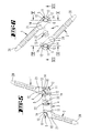
- the latch bar assembly shown in the drawings may be disposed on the inside of a door panel 24 to lock the door panel in a closed position.
- the locking bar assembly has a drive lever 3, in particular made of plastic as an injection molded part, which in perspective in the FIGS. 11 and 12 is shown. It is a two-armed flat lever 3, which has a drive pin 4 in the middle of the lever, with which the drive lever 3 can be coupled to a closing member of a shooting cylinder or to an operating shaft of a door handle.
- For torque transmission is a front side recess 22.
- For axial captivation of the drive pin 4 to the lock cylinder or the pusher is a circumferential groove 23 is shown beyond also a Endanschlagrippe.
- the two ends facing away from each other 3 'of the drive lever 3 have on the two ends facing away from each other on a bearing pin 5.
- the diametrically opposite bearing pin 5 have mutually aligned axes.
- the bearing journals 5 have an equal distance from the axis of rotation of the lever 3 defined by the drive pin 4.
- the journals 5 are designed identically.
- the opposite bearing journals 5 are only angularly offset by 90 ° to each other.
- the bearing pin 5 has a shaft 10, with which the bearing pin 5 with the same material the lever body 3 is connected.
- the shaft 10 has a circular outline.
- the shaft 10 is followed by a cone-shaped portion, which forms a neck 7. From the into the FIGS. 7 to 10 shown sections, it can be seen that the conical surface 8 tapers in the direction of the free end of the bearing pin 5.
- the conical surface 8 merges with the formation of a step 9 in a head 6, which has an outer diameter corresponding to that of the shaft 10.
- the step 9 forms together with the conical surface 8 a neck 7, which has a diameter which is smaller than the diameter of the shank 10 and the head 6, respectively.
- a further conical surface 11 adjoins the end face of the head.
- FIGS. 11 and 12 protrude from the head 6 diametrically opposite projections 12 in the radial direction.
- the projections of the arranged on the same broad side of the lever 3 bearing pin 5 extend in a parallel direction to each other.
- the projections 12 of the bearing journal of the opposite broad sides of the lever 3 are offset by 90 ° to each other.
- the locking bars 1, 2 are designed the same.
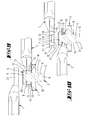
- the in the FIGS. 1 to 15 Lock bars shown differ from those in the FIG. 16 bar shown 1, 2 only in that they are straight, while the in FIG. 16 bar shown has a bend.
- the locking bars 1, 2 have at their free ends a bolt head 20, which can be designed pointed.
- the bolt head can also be designed prismatic be.
- the bolt head 20 opposite end of the locking bar 1, 2 forms a hinge portion 21.
- the locking bar 1, 2 is flattened.
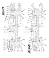
- the flattened hinge section 21 has a bearing opening 13, which has a central area with a substantially circular floor plan. At this circular central region of the bearing opening 13, opposite recesses 14 close.
- the straight line defined by the recesses 14 extends approximately at a 45 ° angle to the longitudinal extension direction of the locking bars 1, 2.
- the central region of the bearing opening 13 has a plurality of axially in the axial direction of the bearing opening 13 consecutive axial sections.
- the bearing opening 13 forms a cone portion 19.
- This cone section 19 forms a finding profiling in order to set up the bearing opening 13 on the head 6. It corresponds to the conical surface 11 of the head 6.
- the conical surface 19 is adjoined by an axial section 18, the diameter of which is greater than the diameter of the head 6 or of the shaft 10.
- This diameter-larger axial section 18 proceeds to form a transition section 17, which in turn has a cone shape, in a smaller diameter axial section 16 via.
- the diameter of the small diameter axial section 16 is less than the diameter of the core portion of the head 6 and the diameter of the shaft 10.
- the diameter of the smaller diameter portion 16 is larger than the diameter of the neck 7, so that in the connected state, the conical Transition portion 17 can be supported on the cone portion 8 of the pin 5 such that the lever 3 facing out wide side surface of the Anlenkabêtes 21 from the broadside of the lever 3 is removed.
- the inner cylindrical portion 16 is sharp-edged in the broad side surface of the Anlenkabêtes 21 over.
- the wall 15 of the respective recess 14 is step-free in the exemplary embodiment. Its inner contour corresponds to the outline contour of the projection 12, so that the projection 12 can pass through the recess 14. But it is also possible that the recess 14 has a certain undersize, so that the projection 12 can only penetrate through the recess 14 by applying a correspondingly large axial force.
- the oblique angle is so flat that a large axial force is required to release the locking bar 1 again from the bearing pin 5.
- This axial force is greater than the axial force required to connect the bearing opening and bearing pin 5.
- the second axial position, which can take the locking bar 1, 2 with respect to the bearing pin 5 is in the FIG. 8 shown on the right.
- the transitional portion 17 rests on the transition region of the conical surface 8 to the shaft 10.
- the shaft 10 is located axially at the height of the larger diameter axial section 18th
- FIGS. 3 and 4 It can be seen that the locking bars are so articulated to the lever 3, that the projections 12 do not run on a 90 ° rotation of the lever 3 between the open position and the locking position on their associated recesses. If the lever 3 between the open position and locking position in the opposite direction, ie rotated clockwise, the locking bars 1, 2 are clipped with the arranged on the back of the lever 3 bearing pin 5, as it FIG. 15 shows.
- the recesses 14 are in such an orientation to the longitudinal extent of the locking bar 1, 2 or lie the projections 12 in such an orientation to the longitudinal extension of the drive lever 3, that they in the respective end positions of the drive lever 3, the open position or a locking position correspond, each at a 45 ° angle to each other. In the reciprocating motion, the projections 12 overflow a position in which they occupy a 90 ° angle to the extension direction of the recesses.
Landscapes
- Engineering & Computer Science (AREA)
- Mechanical Engineering (AREA)
- Pivots And Pivotal Connections (AREA)
Applications Claiming Priority (1)
| Application Number | Priority Date | Filing Date | Title |
|---|---|---|---|
| DE202012100276U DE202012100276U1 (de) | 2012-01-26 | 2012-01-26 | Riegelstangenanordnung insbesondere an einem Schrankverschluss |
Publications (3)
| Publication Number | Publication Date |
|---|---|
| EP2620573A2 true EP2620573A2 (fr) | 2013-07-31 |
| EP2620573A3 EP2620573A3 (fr) | 2016-04-20 |
| EP2620573B1 EP2620573B1 (fr) | 2019-04-10 |
Family
ID=47594578
Family Applications (1)
| Application Number | Title | Priority Date | Filing Date |
|---|---|---|---|
| EP13152310.2A Active EP2620573B1 (fr) | 2012-01-26 | 2013-01-23 | Agencement de tige de verrouillage, notamment sur une fermeture d'armoire |
Country Status (2)
| Country | Link |
|---|---|
| EP (1) | EP2620573B1 (fr) |
| DE (1) | DE202012100276U1 (fr) |
Citations (1)
| Publication number | Priority date | Publication date | Assignee | Title |
|---|---|---|---|---|
| DE6606725U (de) | 1965-06-29 | 1970-11-26 | Weber & Co | Riegelstangenverschluss. |
Family Cites Families (9)
| Publication number | Priority date | Publication date | Assignee | Title |
|---|---|---|---|---|
| US2581885A (en) * | 1948-12-22 | 1952-01-08 | Stanley Works | Connecting means for door latches |
| DE1153571B (de) * | 1957-06-29 | 1963-08-29 | Helmut Alder Dipl Ing | Verriegelungseinrichtung |
| DE2815484B2 (de) * | 1978-04-10 | 1980-02-28 | Fa. Hans Kloeber, 5828 Ennepetal | Feststellvorrichtung für Fenster, insbesondere Dachfenster |
| DE8803862U1 (de) * | 1988-03-22 | 1988-06-01 | Steinbach & Vollmann Gmbh & Co, 5628 Heiligenhaus | Stangenverschluß für Türen |
| DE9406576U1 (de) * | 1994-04-20 | 1994-08-04 | Emka Beschlagteile Gmbh & Co Kg, 42551 Velbert | Stangenverschluß |
| DE29613066U1 (de) * | 1996-07-27 | 1996-09-26 | Gretsch-Unitas GmbH Baubeschläge, 71254 Ditzingen | Vorrichtung zum Begrenzen der Öffnungsweite von Drehflügeln |
| FR2822877B1 (fr) * | 2001-03-29 | 2004-01-16 | Schneider Electric Ind Sa | Dispositif de fermeture pour coffret |
| FR2829521B3 (fr) * | 2001-09-12 | 2003-12-05 | Ronis Sa | Serrure encastrable a poignee tournante |
| AT11490U1 (de) * | 2009-07-08 | 2010-11-15 | Roto Frank Ag | Verbindungselemente zum verbinden zweier teile eines stulps |
-
2012
- 2012-01-26 DE DE202012100276U patent/DE202012100276U1/de not_active Expired - Lifetime
-
2013
- 2013-01-23 EP EP13152310.2A patent/EP2620573B1/fr active Active
Patent Citations (1)
| Publication number | Priority date | Publication date | Assignee | Title |
|---|---|---|---|---|
| DE6606725U (de) | 1965-06-29 | 1970-11-26 | Weber & Co | Riegelstangenverschluss. |
Also Published As
| Publication number | Publication date |
|---|---|
| DE202012100276U1 (de) | 2013-05-02 |
| EP2620573A3 (fr) | 2016-04-20 |
| EP2620573B1 (fr) | 2019-04-10 |
Similar Documents
| Publication | Publication Date | Title |
|---|---|---|
| DE102006005998B4 (de) | Schraubenmutter mit mindestens zwei Teilen | |
| EP0632699B1 (fr) | Dispositif a pression pour le blocage de lacets | |
| EP1153186B1 (fr) | Raccord permettant de connecter deux parois minces | |
| DE102007044088A1 (de) | Binär codierter Schlüssel und manipulationssicheres Schloss | |
| DE202014101515U1 (de) | Klappfahrradspezifische zweifache Schnelllöseeinheit | |
| EP1898105A2 (fr) | Fermeture rapide destinée à la liaison de deux composants | |
| DE202007014504U1 (de) | Stangenverschluss mit hebelförmigem Stangenantrieb | |
| DE102017127750A1 (de) | Drahtgewindeeinsatz | |
| EP0636798A2 (fr) | Elément de fixation rotatif | |
| DE4319295C2 (de) | Schließeinrichtung für Fahrzeuge | |
| DE202005021315U1 (de) | Kupplungseinrichtung mit einer Panikfunktion für elektromechanische Feststellvorrichtungen | |
| DE102009014084A1 (de) | Scharnier für einen Kraftwagen | |
| EP2088263A1 (fr) | Cylindre de fermeture doté d'un retour automatique de l'organe de fermeture | |
| DE29610293U1 (de) | Karabinerhaken | |
| DE69828298T2 (de) | Vorrichtungen zum herstellen einer verbindung | |
| DE102014113714A1 (de) | Möbelscharnier | |
| WO2020169395A1 (fr) | Écrou en deux parties présentant une force de pression élevée | |
| DE102014110064A1 (de) | Wischvorrichtung zum Reinigen einer Fahrzeugscheibe und Wischblatt für eine Wischvorrichtung | |
| EP3094799B1 (fr) | Poignée de porte de véhicule | |
| WO2013117255A1 (fr) | Système de fermeture, notamment pour des chaînes de protection pour pneus | |
| EP1561890A1 (fr) | Dispositif de blocage de porte | |
| EP2620573B1 (fr) | Agencement de tige de verrouillage, notamment sur une fermeture d'armoire | |
| DE202008011611U1 (de) | Einrichtung zum Impantieren eines Zwischenwirbelimplantates | |
| DE102008034070A1 (de) | Schließzylinder mit federkraftunterstützter Zylinderkernrückstellung | |
| EP1936083B1 (fr) | Dispositif de support pour une charnière d'une unité de fermeture |
Legal Events
| Date | Code | Title | Description |
|---|---|---|---|
| PUAI | Public reference made under article 153(3) epc to a published international application that has entered the european phase |
Free format text: ORIGINAL CODE: 0009012 |
|
| AK | Designated contracting states |
Kind code of ref document: A2 Designated state(s): AL AT BE BG CH CY CZ DE DK EE ES FI FR GB GR HR HU IE IS IT LI LT LU LV MC MK MT NL NO PL PT RO RS SE SI SK SM TR |
|
| AX | Request for extension of the european patent |
Extension state: BA ME |
|
| PUAL | Search report despatched |
Free format text: ORIGINAL CODE: 0009013 |
|
| AK | Designated contracting states |
Kind code of ref document: A3 Designated state(s): AL AT BE BG CH CY CZ DE DK EE ES FI FR GB GR HR HU IE IS IT LI LT LU LV MC MK MT NL NO PL PT RO RS SE SI SK SM TR |
|
| AX | Request for extension of the european patent |
Extension state: BA ME |
|
| RIC1 | Information provided on ipc code assigned before grant |
Ipc: E05C 9/04 20060101ALI20160317BHEP Ipc: E05C 9/16 20060101AFI20160317BHEP |
|
| 17P | Request for examination filed |
Effective date: 20160808 |
|
| RBV | Designated contracting states (corrected) |
Designated state(s): AL AT BE BG CH CY CZ DE DK EE ES FI FR GB GR HR HU IE IS IT LI LT LU LV MC MK MT NL NO PL PT RO RS SE SI SK SM TR |
|
| REG | Reference to a national code |
Ref country code: DE Ref legal event code: R079 Ref document number: 502013012571 Country of ref document: DE Free format text: PREVIOUS MAIN CLASS: E05C0009160000 Ipc: E05C0009040000 |
|
| GRAP | Despatch of communication of intention to grant a patent |
Free format text: ORIGINAL CODE: EPIDOSNIGR1 |
|
| STAA | Information on the status of an ep patent application or granted ep patent |
Free format text: STATUS: GRANT OF PATENT IS INTENDED |
|
| RIC1 | Information provided on ipc code assigned before grant |
Ipc: E05C 9/04 20060101AFI20180921BHEP Ipc: E05C 9/20 20060101ALI20180921BHEP |
|
| INTG | Intention to grant announced |
Effective date: 20181018 |
|
| GRAS | Grant fee paid |
Free format text: ORIGINAL CODE: EPIDOSNIGR3 |
|
| GRAA | (expected) grant |
Free format text: ORIGINAL CODE: 0009210 |
|
| STAA | Information on the status of an ep patent application or granted ep patent |
Free format text: STATUS: THE PATENT HAS BEEN GRANTED |
|
| AK | Designated contracting states |
Kind code of ref document: B1 Designated state(s): AL AT BE BG CH CY CZ DE DK EE ES FI FR GB GR HR HU IE IS IT LI LT LU LV MC MK MT NL NO PL PT RO RS SE SI SK SM TR |
|
| REG | Reference to a national code |
Ref country code: GB Ref legal event code: FG4D Free format text: NOT ENGLISH |
|
| REG | Reference to a national code |
Ref country code: CH Ref legal event code: EP Ref country code: AT Ref legal event code: REF Ref document number: 1118848 Country of ref document: AT Kind code of ref document: T Effective date: 20190415 |
|
| REG | Reference to a national code |
Ref country code: IE Ref legal event code: FG4D Free format text: LANGUAGE OF EP DOCUMENT: GERMAN |
|
| REG | Reference to a national code |
Ref country code: DE Ref legal event code: R096 Ref document number: 502013012571 Country of ref document: DE |
|
| REG | Reference to a national code |
Ref country code: NL Ref legal event code: MP Effective date: 20190410 |
|
| REG | Reference to a national code |
Ref country code: LT Ref legal event code: MG4D |
|
| PG25 | Lapsed in a contracting state [announced via postgrant information from national office to epo] |
Ref country code: NL Free format text: LAPSE BECAUSE OF FAILURE TO SUBMIT A TRANSLATION OF THE DESCRIPTION OR TO PAY THE FEE WITHIN THE PRESCRIBED TIME-LIMIT Effective date: 20190410 |
|
| PG25 | Lapsed in a contracting state [announced via postgrant information from national office to epo] |
Ref country code: PT Free format text: LAPSE BECAUSE OF FAILURE TO SUBMIT A TRANSLATION OF THE DESCRIPTION OR TO PAY THE FEE WITHIN THE PRESCRIBED TIME-LIMIT Effective date: 20190910 Ref country code: LT Free format text: LAPSE BECAUSE OF FAILURE TO SUBMIT A TRANSLATION OF THE DESCRIPTION OR TO PAY THE FEE WITHIN THE PRESCRIBED TIME-LIMIT Effective date: 20190410 Ref country code: HR Free format text: LAPSE BECAUSE OF FAILURE TO SUBMIT A TRANSLATION OF THE DESCRIPTION OR TO PAY THE FEE WITHIN THE PRESCRIBED TIME-LIMIT Effective date: 20190410 Ref country code: FI Free format text: LAPSE BECAUSE OF FAILURE TO SUBMIT A TRANSLATION OF THE DESCRIPTION OR TO PAY THE FEE WITHIN THE PRESCRIBED TIME-LIMIT Effective date: 20190410 Ref country code: NO Free format text: LAPSE BECAUSE OF FAILURE TO SUBMIT A TRANSLATION OF THE DESCRIPTION OR TO PAY THE FEE WITHIN THE PRESCRIBED TIME-LIMIT Effective date: 20190710 Ref country code: AL Free format text: LAPSE BECAUSE OF FAILURE TO SUBMIT A TRANSLATION OF THE DESCRIPTION OR TO PAY THE FEE WITHIN THE PRESCRIBED TIME-LIMIT Effective date: 20190410 Ref country code: SE Free format text: LAPSE BECAUSE OF FAILURE TO SUBMIT A TRANSLATION OF THE DESCRIPTION OR TO PAY THE FEE WITHIN THE PRESCRIBED TIME-LIMIT Effective date: 20190410 Ref country code: ES Free format text: LAPSE BECAUSE OF FAILURE TO SUBMIT A TRANSLATION OF THE DESCRIPTION OR TO PAY THE FEE WITHIN THE PRESCRIBED TIME-LIMIT Effective date: 20190410 |
|
| PG25 | Lapsed in a contracting state [announced via postgrant information from national office to epo] |
Ref country code: BG Free format text: LAPSE BECAUSE OF FAILURE TO SUBMIT A TRANSLATION OF THE DESCRIPTION OR TO PAY THE FEE WITHIN THE PRESCRIBED TIME-LIMIT Effective date: 20190710 Ref country code: LV Free format text: LAPSE BECAUSE OF FAILURE TO SUBMIT A TRANSLATION OF THE DESCRIPTION OR TO PAY THE FEE WITHIN THE PRESCRIBED TIME-LIMIT Effective date: 20190410 Ref country code: RS Free format text: LAPSE BECAUSE OF FAILURE TO SUBMIT A TRANSLATION OF THE DESCRIPTION OR TO PAY THE FEE WITHIN THE PRESCRIBED TIME-LIMIT Effective date: 20190410 Ref country code: GR Free format text: LAPSE BECAUSE OF FAILURE TO SUBMIT A TRANSLATION OF THE DESCRIPTION OR TO PAY THE FEE WITHIN THE PRESCRIBED TIME-LIMIT Effective date: 20190711 Ref country code: PL Free format text: LAPSE BECAUSE OF FAILURE TO SUBMIT A TRANSLATION OF THE DESCRIPTION OR TO PAY THE FEE WITHIN THE PRESCRIBED TIME-LIMIT Effective date: 20190410 |
|
| PG25 | Lapsed in a contracting state [announced via postgrant information from national office to epo] |
Ref country code: IS Free format text: LAPSE BECAUSE OF FAILURE TO SUBMIT A TRANSLATION OF THE DESCRIPTION OR TO PAY THE FEE WITHIN THE PRESCRIBED TIME-LIMIT Effective date: 20190810 |
|
| REG | Reference to a national code |
Ref country code: DE Ref legal event code: R097 Ref document number: 502013012571 Country of ref document: DE |
|
| PG25 | Lapsed in a contracting state [announced via postgrant information from national office to epo] |
Ref country code: SK Free format text: LAPSE BECAUSE OF FAILURE TO SUBMIT A TRANSLATION OF THE DESCRIPTION OR TO PAY THE FEE WITHIN THE PRESCRIBED TIME-LIMIT Effective date: 20190410 Ref country code: EE Free format text: LAPSE BECAUSE OF FAILURE TO SUBMIT A TRANSLATION OF THE DESCRIPTION OR TO PAY THE FEE WITHIN THE PRESCRIBED TIME-LIMIT Effective date: 20190410 Ref country code: DK Free format text: LAPSE BECAUSE OF FAILURE TO SUBMIT A TRANSLATION OF THE DESCRIPTION OR TO PAY THE FEE WITHIN THE PRESCRIBED TIME-LIMIT Effective date: 20190410 Ref country code: RO Free format text: LAPSE BECAUSE OF FAILURE TO SUBMIT A TRANSLATION OF THE DESCRIPTION OR TO PAY THE FEE WITHIN THE PRESCRIBED TIME-LIMIT Effective date: 20190410 Ref country code: CZ Free format text: LAPSE BECAUSE OF FAILURE TO SUBMIT A TRANSLATION OF THE DESCRIPTION OR TO PAY THE FEE WITHIN THE PRESCRIBED TIME-LIMIT Effective date: 20190410 |
|
| PLBE | No opposition filed within time limit |
Free format text: ORIGINAL CODE: 0009261 |
|
| STAA | Information on the status of an ep patent application or granted ep patent |
Free format text: STATUS: NO OPPOSITION FILED WITHIN TIME LIMIT |
|
| PG25 | Lapsed in a contracting state [announced via postgrant information from national office to epo] |
Ref country code: SM Free format text: LAPSE BECAUSE OF FAILURE TO SUBMIT A TRANSLATION OF THE DESCRIPTION OR TO PAY THE FEE WITHIN THE PRESCRIBED TIME-LIMIT Effective date: 20190410 Ref country code: IT Free format text: LAPSE BECAUSE OF FAILURE TO SUBMIT A TRANSLATION OF THE DESCRIPTION OR TO PAY THE FEE WITHIN THE PRESCRIBED TIME-LIMIT Effective date: 20190410 |
|
| 26N | No opposition filed |
Effective date: 20200113 |
|
| PG25 | Lapsed in a contracting state [announced via postgrant information from national office to epo] |
Ref country code: TR Free format text: LAPSE BECAUSE OF FAILURE TO SUBMIT A TRANSLATION OF THE DESCRIPTION OR TO PAY THE FEE WITHIN THE PRESCRIBED TIME-LIMIT Effective date: 20190410 |
|
| PG25 | Lapsed in a contracting state [announced via postgrant information from national office to epo] |
Ref country code: SI Free format text: LAPSE BECAUSE OF FAILURE TO SUBMIT A TRANSLATION OF THE DESCRIPTION OR TO PAY THE FEE WITHIN THE PRESCRIBED TIME-LIMIT Effective date: 20190410 |
|
| PG25 | Lapsed in a contracting state [announced via postgrant information from national office to epo] |
Ref country code: MC Free format text: LAPSE BECAUSE OF FAILURE TO SUBMIT A TRANSLATION OF THE DESCRIPTION OR TO PAY THE FEE WITHIN THE PRESCRIBED TIME-LIMIT Effective date: 20190410 |
|
| REG | Reference to a national code |
Ref country code: CH Ref legal event code: PL |
|
| GBPC | Gb: european patent ceased through non-payment of renewal fee |
Effective date: 20200123 |
|
| REG | Reference to a national code |
Ref country code: BE Ref legal event code: MM Effective date: 20200131 |
|
| PG25 | Lapsed in a contracting state [announced via postgrant information from national office to epo] |
Ref country code: GB Free format text: LAPSE BECAUSE OF NON-PAYMENT OF DUE FEES Effective date: 20200123 Ref country code: LU Free format text: LAPSE BECAUSE OF NON-PAYMENT OF DUE FEES Effective date: 20200123 |
|
| PG25 | Lapsed in a contracting state [announced via postgrant information from national office to epo] |
Ref country code: LI Free format text: LAPSE BECAUSE OF NON-PAYMENT OF DUE FEES Effective date: 20200131 Ref country code: BE Free format text: LAPSE BECAUSE OF NON-PAYMENT OF DUE FEES Effective date: 20200131 Ref country code: CH Free format text: LAPSE BECAUSE OF NON-PAYMENT OF DUE FEES Effective date: 20200131 |
|
| PG25 | Lapsed in a contracting state [announced via postgrant information from national office to epo] |
Ref country code: IE Free format text: LAPSE BECAUSE OF NON-PAYMENT OF DUE FEES Effective date: 20200123 |
|
| REG | Reference to a national code |
Ref country code: AT Ref legal event code: MM01 Ref document number: 1118848 Country of ref document: AT Kind code of ref document: T Effective date: 20200123 |
|
| PG25 | Lapsed in a contracting state [announced via postgrant information from national office to epo] |
Ref country code: AT Free format text: LAPSE BECAUSE OF NON-PAYMENT OF DUE FEES Effective date: 20200123 |
|
| PG25 | Lapsed in a contracting state [announced via postgrant information from national office to epo] |
Ref country code: MT Free format text: LAPSE BECAUSE OF FAILURE TO SUBMIT A TRANSLATION OF THE DESCRIPTION OR TO PAY THE FEE WITHIN THE PRESCRIBED TIME-LIMIT Effective date: 20190410 Ref country code: CY Free format text: LAPSE BECAUSE OF FAILURE TO SUBMIT A TRANSLATION OF THE DESCRIPTION OR TO PAY THE FEE WITHIN THE PRESCRIBED TIME-LIMIT Effective date: 20190410 |
|
| PG25 | Lapsed in a contracting state [announced via postgrant information from national office to epo] |
Ref country code: MK Free format text: LAPSE BECAUSE OF FAILURE TO SUBMIT A TRANSLATION OF THE DESCRIPTION OR TO PAY THE FEE WITHIN THE PRESCRIBED TIME-LIMIT Effective date: 20190410 |
|
| PGFP | Annual fee paid to national office [announced via postgrant information from national office to epo] |
Ref country code: FR Payment date: 20250122 Year of fee payment: 13 |
|
| PGFP | Annual fee paid to national office [announced via postgrant information from national office to epo] |
Ref country code: DE Payment date: 20260120 Year of fee payment: 14 |