EP2620231B1 - Feste struktur zur abschirmung gegen anorganische abfälle und verfahren zur herstellung der festen struktur zur abschirmung gegen anorganische abfälle - Google Patents
Feste struktur zur abschirmung gegen anorganische abfälle und verfahren zur herstellung der festen struktur zur abschirmung gegen anorganische abfälle Download PDFInfo
- Publication number
- EP2620231B1 EP2620231B1 EP12832701.2A EP12832701A EP2620231B1 EP 2620231 B1 EP2620231 B1 EP 2620231B1 EP 12832701 A EP12832701 A EP 12832701A EP 2620231 B1 EP2620231 B1 EP 2620231B1
- Authority
- EP
- European Patent Office
- Prior art keywords
- inorganic waste
- shield layer
- space
- lateral
- compacted
- Prior art date
- Legal status (The legal status is an assumption and is not a legal conclusion. Google has not performed a legal analysis and makes no representation as to the accuracy of the status listed.)
- Active
Links
Images



Classifications
-
- B—PERFORMING OPERATIONS; TRANSPORTING
- B09—DISPOSAL OF SOLID WASTE; RECLAMATION OF CONTAMINATED SOIL
- B09B—DISPOSAL OF SOLID WASTE NOT OTHERWISE PROVIDED FOR
- B09B1/00—Dumping solid waste
-
- B—PERFORMING OPERATIONS; TRANSPORTING
- B09—DISPOSAL OF SOLID WASTE; RECLAMATION OF CONTAMINATED SOIL
- B09B—DISPOSAL OF SOLID WASTE NOT OTHERWISE PROVIDED FOR
- B09B3/00—Destroying solid waste or transforming solid waste into something useful or harmless
- B09B3/30—Destroying solid waste or transforming solid waste into something useful or harmless involving mechanical treatment
- B09B3/32—Compressing or compacting
-
- B—PERFORMING OPERATIONS; TRANSPORTING
- B09—DISPOSAL OF SOLID WASTE; RECLAMATION OF CONTAMINATED SOIL
- B09B—DISPOSAL OF SOLID WASTE NOT OTHERWISE PROVIDED FOR
- B09B3/00—Destroying solid waste or transforming solid waste into something useful or harmless
- B09B3/20—Agglomeration, binding or encapsulation of solid waste
-
- G—PHYSICS
- G21—NUCLEAR PHYSICS; NUCLEAR ENGINEERING
- G21F—PROTECTION AGAINST X-RADIATION, GAMMA RADIATION, CORPUSCULAR RADIATION OR PARTICLE BOMBARDMENT; TREATING RADIOACTIVELY CONTAMINATED MATERIAL; DECONTAMINATION ARRANGEMENTS THEREFOR
- G21F9/00—Treating radioactively contaminated material; Decontamination arrangements therefor
- G21F9/04—Treating liquids
- G21F9/20—Disposal of liquid waste
- G21F9/24—Disposal of liquid waste by storage in the ground; by storage under water, e.g. in ocean
-
- G—PHYSICS
- G21—NUCLEAR PHYSICS; NUCLEAR ENGINEERING
- G21F—PROTECTION AGAINST X-RADIATION, GAMMA RADIATION, CORPUSCULAR RADIATION OR PARTICLE BOMBARDMENT; TREATING RADIOACTIVELY CONTAMINATED MATERIAL; DECONTAMINATION ARRANGEMENTS THEREFOR
- G21F9/00—Treating radioactively contaminated material; Decontamination arrangements therefor
- G21F9/28—Treating solids
- G21F9/30—Processing
- G21F9/301—Processing by fixation in stable solid media
- G21F9/302—Processing by fixation in stable solid media in an inorganic matrix
-
- G—PHYSICS
- G21—NUCLEAR PHYSICS; NUCLEAR ENGINEERING
- G21F—PROTECTION AGAINST X-RADIATION, GAMMA RADIATION, CORPUSCULAR RADIATION OR PARTICLE BOMBARDMENT; TREATING RADIOACTIVELY CONTAMINATED MATERIAL; DECONTAMINATION ARRANGEMENTS THEREFOR
- G21F9/00—Treating radioactively contaminated material; Decontamination arrangements therefor
- G21F9/28—Treating solids
- G21F9/34—Disposal of solid waste
Definitions
- the present invention relates to an inorganic waste solidification shield structure that shields a compacted formation obtained by filling in banking material containing inorganic waste at a final disposal site, and a manufacturing method thereof.
- Patent Literature 1 In the related art, as a compacted formation of this type, there exists the below Patent Literature 1, by the present applicant.
- Such a compacted formation is made to be a cement solidification by repeatedly pouring and compressing banking material, being a mixture of cement and inorganic waste, into unit divisions enclosed by walls, and finally solidifying the result. Then, by expanding the unit divisions horizontally and also vertically, it is possible to completely prevent hazardous substances in the inorganic waste from eluting in rainwater, with the entire disposal site as cement solidifications.
- Patent Literature 1 Japanese Patent No. 4317260
- the present applicant ascertained by diligent experiment and research that it is desirable to prevent the inorganic waste in each of the compacted formations from coming into contact with rainwater, even during the process of successively producing compacted formations at a final disposal site.
- the present invention takes as an objective to provide a method of manufacturing an inorganic waste solidification shield structureable to avoid contact between inorganic waste and rainwater by shielding compacted formations obtained by filling in banking material containing waste at a final disposal site.
- shields are formed on the top and lateral faces of compacted formations formed as compacted formations in the first to third steps according to the inorganic waste disposal method in the Patent Literature 1 by the present applicant.
- the fourth step there is formed on the top face of the compacted formation an upper primary shield layer obtained by evenly spreading and compacting gravel on top of the second compacted formation and the third compacted formation.
- the upper capping layer is formed by evenly spreading the covering material consisting of the cement mixture on top, and evenly spreading and compacting gravel onto the evenly spread covering material.
- the upper secondary shield layer is formed by evenly spreading gravel on top.
- the upper primary shield layer, the upper capping layer, and the upper secondary shield layer are integrated by placing the weight on top of the upper secondary shield layer and allowing the curing period to elapse, thereby making it possible to form a strong upper shield structure.
- the fifth step first there is formed on the lateral face of the compacted formation the lateral primary shield layer in which the coating is applied. Additionally, there is formed the lateral capping layer by applying the thick coating thereover. Additionally, there is formed the lateral secondary shield layer by applying the coating thereover.
- the inorganic waste solidification shield structure in accordance with the third aspect of the invention, it is possible to shield the top and lateral faces of the compacted formation obtained by filling in banking material containing inorganic waste at the final disposal site, and avoid contact between inorganic waste and rainwater.
- the divisions to be filled with banking material containing inorganic waste can be defined as a fill direction X and a fill direction Y orthogonal to the fill direction X in the same plane, and once filling in the same plane is finished, can be expanded by defining a next plane in the height direction Z.
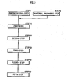
- the divisions (Xn, Yn) on a level Zn are divided by walls to form a fill space Wn, and the fill space Wn is partitioned in the horizontal direction to form a first space 1 and a second space 2 ( FIG. 2 , step 1: preprocessing step).
- the fill space Wn is first formed by the walls of already-filled adjacent divisions (Xn, Yn-1) and (Xn-1, Yn), and walls formed by standing up a metal plate 110 onto temporary dams 100, as illustrated in FIG. 3 .
- temporary dams 100 and a metal plate 110 are disposed for the fill direction X, while temporary dams 100' and a metal plate 110' are disposed for the orthogonal direction Y.
- the fill space Wn forms a second space 2 where the internal partitioning temporary dams 200 are disposed, and the remaining first space 1.
- FIG. 4(A) illustrates how the fill space Wn is partitioned into the first space 1 and the second space 2 by the partitioning metal plate 210 in this way.
- the internal partitioning temporary dams 200 have a tapered face in which the face adjoining the partitioning metal plate 210 becomes narrower proceeding from top to bottom.
- step 1 material such as a covering material consisting of a type-A banking material, a type-B banking material, and a cement mixture is prepared in advance ( FIG. 2 , step 5: material preparing step).
- a mixing apparatus (not illustrated) prepares the type-A banking material by mixing type-A inorganic waste, which does not contain incinerated ash with high concentrations of hazardous substances, with added cement and water, and also prepares the type-B banking material by mixing type-B inorganic waste, which does contain incinerated ash with high concentrations of hazardous substances, with added cement and water. Also, a cement mixture obtained by mixing cement with added substances such as sand and water (mortar, for example) is prepared as a covering material.
- type-A inorganic waste is waste with a concentration of hazardous substances that is simply less than that of the type-B inorganic waste (irrespective of a reference value).
- a first compacted formation 10 is formed by pouring and compacting the type-B banking material into the first space 1 ( FIG. 2 , step 10: first step).
- the first compacted formation 10 is formed by pouring type-B banking material, and then setting and compacting the poured type-B banking material, while leaving fixed upper spaces 1a and 1b at the top of the first space 1.
- a second compacted formation 20 is formed by pouring and compacting the type-A banking material into the upper space 1a over the first compacted formation 10 ( FIG. 2 , step 20: second step).
- the second compacted formation 20 is formed by pouring type-A banking material into the upper space 1a over the first compacted formation 10 (leaving the upper space 1b), and then setting and compacting the poured type-A banking material.
- the type-B banking material it is preferable to not have the type-B banking material and the type-A banking material come into direct contact, by evenly spreading and setting fresh gravel over the first compacted formation 10 before pouring the type-A banking material. This also exhibits a shielding effect due to the gravel in the case where the type-B banking material contains radioactive substances.
- FIG. 4(B) illustrates how the first compacted formation 10 and the second compacted formation 20 are formed in the first space 1 in this way.
- step 30 third step.
- the third compacted formation 30 is formed by pouring type-A banking material, and then setting and compacting the poured type-A banking material, while leaving the fixed upper space 1b at the top of the second space 2.
- the type-A banking material is poured and set such that the surface of the third compacted formation 30 becomes continuous with the second compacted formation 20.
- FIG. 4(C) illustrates how the third compacted formation 30 is formed in the second space 2 in this way.
- a structure in which a first compacted formation 10, a second compacted formation 20, and a third compacted formation 30 are integrated is equivalent to a compacted formation of the present invention.
- step 40 fourth step.
- an upper primary shield layer 41 is formed by evenly spreading and compacting fresh gravel over the second compacted formation 20 and the third compacted formation 30 (in the upper space 1b), as illustrated by the partially enlarged view in FIG. 5(A) .
- an upper capping layer 42 is formed by evenly spreading the covering material consisting of a cement mixture that was prepared in step 5 (mortar, for example), and then evenly spreading and compacting gravel onto the evenly spread covering material. Additionally, gravel is evenly spread over the upper capping layer 42.
- the upper primary shield layer 41, the upper capping layer 42, and an upper secondary shield layer 43 are integrated by spreading a cover metal plate (not illustrated) so as to cover the entire top surface of the upper secondary shield layer 43, placing a weight (not illustrated) on the cover metal plate, and allowing a curing period to elapse. At this point, the surface f becomes continuous with the adjacent divisions. Then, after the curing period elapses, the cover metal plate and the weight are removed.
- FIG. 5(B) illustrates the upper shield structure 40 obtained as a result.
- the upper shield structure 40 By forming the upper shield structure 40 integrating the three layers of shields 41 to 43 on the top face of the compacted formations, contact between inorganic waste and rainwater is completely avoided at the top face of the compacted formations.
- step 50 fifth step.
- the temporary dams 100' and the metal plate 110' in the Y direction orthogonal to the fill direction X are kept until starting to fill the next division (Xn, Yn+1).
- filling of the next division (Xn, Yn+1) may be started in a comparatively short period after finishing the filling of the current division (Xn, Yn), it is preferable to cover the division boundary portions given by the metal plate 110' with a vinyl sheet or the like as necessary until starting the next filling.
- a lateral primary shield layer 51 is formed by applying a coating (a highly waterproof building exterior coating, such as an epoxy resin undercoating, for example) to the exposed lateral face of the third compacted formation 30.
- a lateral capping layer 52 is formed by applying a thick coating (a highly waterproof building exterior coating, such as a thick plastic emulsion finishing coat material, for example) to the lateral primary shield layer 51.
- a lateral secondary shield layer 53 is formed by applying a coating (a highly waterproof building exterior coating, such as an epoxy resin finish coating, for example) to the lateral capping layer 52.
- the lateral primary shield layer 51, the lateral capping layer 52, and the lateral secondary shield layer 53 after first grouting the depressions with covering material in advance.
- a lateral shield structure 50 By forming a lateral shield structure 50 with the three layers of shields 51 to 53 on the lateral face of the compacted formations, contact between inorganic waste and rainwater is completely avoided at the lateral face of the compacted formations.
- an inorganic waste solidification shield structure that forms an upper shield structure 40 and a lateral shield structure 50 at the top and lateral faces of a compacted formation, it is possible to shield the top and lateral faces of a compacted formation and avoid contact between inorganic waste and rainwater. It is possible to completely prevent the eluting in rainwater of inorganic waste contained in the compacted formation.
Landscapes
- Engineering & Computer Science (AREA)
- Environmental & Geological Engineering (AREA)
- General Engineering & Computer Science (AREA)
- High Energy & Nuclear Physics (AREA)
- Physics & Mathematics (AREA)
- Inorganic Chemistry (AREA)
- Chemical & Material Sciences (AREA)
- Life Sciences & Earth Sciences (AREA)
- Biodiversity & Conservation Biology (AREA)
- General Life Sciences & Earth Sciences (AREA)
- Ocean & Marine Engineering (AREA)
- Oceanography (AREA)
- Sustainable Development (AREA)
- Processing Of Solid Wastes (AREA)
Claims (1)
- Verfahren zur Herstellung einer Abschirmstruktur für die Verfestigung von anorganischem Abfall, die eine verdichtete Formation abschirmt, die durch Einfüllen von Auffüllmaterial, welches anorganischen Abfall aufweist, an einem Endlager erhalten wird, dadurch gekennzeichnet, dass es Folgendes umfasst:einen Vorverarbeitungsschritt, der einen ersten Raum (1) und einen zweiten Raum (2) durch Aufteilung in der horizontalen Richtung sicherstellt, wobei ein Raum mit dem Auffüllmaterial gefüllt werden soll, der durch Wände an dem Endlager abgegrenzt ist;einen ersten Schritt, der eine erste verdichtete Formation (10) durch Einfüllen und Verdichten eines Auffüllmaterials vom Typ B bildet, das einen anorganischen Abfall vom Typ B mit hohen Konzentrationen an Gefahrenstoffen enthält, über den ersten Raum (1), der durch den Vorverarbeitungsschritt abgeteilt ist;einen zweiten Schritt, der eine zweite verdichtete Formation (20) durch Einfüllen und Verdichten eines Auffüllmaterials vom Typ A bildet, das einen anorganischen Abfall vom Typ A mit niedrigen Konzentrationen an Gefahrenstoffen enthält, über der ersten Formation (10), die durch den ersten Schritt erhalten wird;wobei die niedrigen Konzentrationen an Gefahrenstoffen des anorganischen Abfalls vom Typ A geringer als die hohen Konzentrationen an Gefahrenstoffen des anorganischen Abfalls vom Typ B sind;einen dritten Schritt, der eine dritte verdichtete Formation (30) durch Entfernen der Aufteilung zwischen dem ersten Raum (1) und dem zweite Raum (2), nach Bilden der zweiten verdichteten Formation (20) durch den zweiten Schritt, und Einfüllen und Verdichten des Auffüllmaterials vom Typ A in den zweiten Raum (2);einen vierten Schritt, der eine obere primäre Abschirmschicht (41) durch gleichmäßiges Verteilen und Verdichten von Kies über der zweiten verdichteten Formation (20) und der dritten verdichteten Formation (30) bildet, die durch den zweiten Schritt und den dritten Schritt erhalten wurden, und bilden einer oberen Deckschicht (42) durch gleichmäßiges Verteilen eines Abdeckmaterials, das aus einer Zementmischung besteht, über der oberen primären Abschirmschicht (41), und durch gleichmäßiges Verteilen und Verdichten von Kies auf das gleichmäßig verteilte Abdeckmaterial zur Bildung einer oberen sekundären Abschirmschicht (43) durch gleichmäßiges Verteilen von Kies über der oberen Deckschicht (42), und Integrieren der oberen primären Abschirmschicht (41), der oberen Deckschicht (42) und der oberen sekundären Abschirmschicht (43) durch Anordnen eines Gewichts auf der oberen sekundären Abschirmschicht (43) und Verstreichenlassen eines Härtungszeitraums; undeinen fünften Schritt, der, nachdem die obere primäre Abschirmschicht (41), die obere Deckschicht (42) und die obere sekundäre Abschirmschicht (43) durch den vierten Schritt integriert sind, eine seitliche primäre Abschirmschicht (51) durch Aufbringen einer Beschichtung auf eine Seitenfläche der dritten verdichteten Formation (30) bildet, die durch Entfernen der Wände freiliegend ist, bilden einer seitlichen Deckschicht (52) durch Aufbringen einer Beschichtung auf die seitlichen primären Abschirmschicht (51) und bilden einer seitlichen sekundären Abschirmschicht (53) durch Aufbringen einer Beschichtung auf die seitliche Deckschicht (52).
Applications Claiming Priority (2)
| Application Number | Priority Date | Filing Date | Title |
|---|---|---|---|
| JP2012207637A JP5188646B1 (ja) | 2012-09-20 | 2012-09-20 | 無機廃棄物固化シールド構造体および無機廃棄物固化シールド構造体の製造方法 |
| PCT/JP2012/082689 WO2013077475A1 (ja) | 2012-09-20 | 2012-12-17 | 無機廃棄物固化シールド構造体および無機廃棄物固化シールド構造体の製造方法 |
Publications (3)
| Publication Number | Publication Date |
|---|---|
| EP2620231A1 EP2620231A1 (de) | 2013-07-31 |
| EP2620231A4 EP2620231A4 (de) | 2014-04-16 |
| EP2620231B1 true EP2620231B1 (de) | 2015-03-18 |
Family
ID=48469896
Family Applications (1)
| Application Number | Title | Priority Date | Filing Date |
|---|---|---|---|
| EP12832701.2A Active EP2620231B1 (de) | 2012-09-20 | 2012-12-17 | Feste struktur zur abschirmung gegen anorganische abfälle und verfahren zur herstellung der festen struktur zur abschirmung gegen anorganische abfälle |
Country Status (3)
| Country | Link |
|---|---|
| EP (1) | EP2620231B1 (de) |
| JP (1) | JP5188646B1 (de) |
| WO (1) | WO2013077475A1 (de) |
Families Citing this family (5)
| Publication number | Priority date | Publication date | Assignee | Title |
|---|---|---|---|---|
| JP5320519B1 (ja) * | 2013-05-14 | 2013-10-23 | 株式会社フジコーポレーション | 廃棄物貯蔵施設の垂直壁構造 |
| JP5380627B1 (ja) * | 2013-05-14 | 2014-01-08 | 株式会社フジコーポレーション | 最終処分場の簡易垂直壁構造 |
| EP2992974B1 (de) * | 2014-10-21 | 2018-07-18 | Fuji Corporation Co., Ltd. | Anlage zur endgültigen endablagerung |
| KR101576503B1 (ko) | 2015-04-03 | 2015-12-11 | 주식회사 이노테라피 | 카테콜 기 및 산화된 카테콜 기가 도입되어 가교된 키토산으로 코팅된 무출혈 주사바늘 |
| JP7454481B2 (ja) * | 2020-10-07 | 2024-03-22 | 鹿島建設株式会社 | 貯蔵施設、及び、貯蔵方法 |
Family Cites Families (5)
| Publication number | Priority date | Publication date | Assignee | Title |
|---|---|---|---|---|
| JP3668440B2 (ja) * | 2001-06-14 | 2005-07-06 | 山形環境保全協同組合 | 廃棄物埋立処理方法、およびそれに使用する廃棄物被膜層 |
| JP5085945B2 (ja) * | 2007-01-19 | 2012-11-28 | 株式会社とわに | 粉粒状廃棄物の処分法 |
| GB2454485A (en) * | 2007-11-08 | 2009-05-13 | Johnson Matthey Plc | Method of disposing of non-nuclear hazardous waste materials |
| JP4317260B1 (ja) * | 2009-03-07 | 2009-08-19 | 株式会社フジコーポレーション | 最終処分場における無機廃棄物分離・一体化による多数の単位固化物成形処分方法並びに多数の単位固化物成形処分構造体 |
| JP4397050B1 (ja) * | 2009-04-01 | 2010-01-13 | 株式会社フジコーポレーション | 最終処分場の埋立廃棄物被覆構造体 |
-
2012
- 2012-09-20 JP JP2012207637A patent/JP5188646B1/ja active Active
- 2012-12-17 EP EP12832701.2A patent/EP2620231B1/de active Active
- 2012-12-17 WO PCT/JP2012/082689 patent/WO2013077475A1/ja not_active Ceased
Also Published As
| Publication number | Publication date |
|---|---|
| EP2620231A1 (de) | 2013-07-31 |
| EP2620231A4 (de) | 2014-04-16 |
| JP2014061473A (ja) | 2014-04-10 |
| JP5188646B1 (ja) | 2013-04-24 |
| WO2013077475A1 (ja) | 2013-05-30 |
Similar Documents
| Publication | Publication Date | Title |
|---|---|---|
| EP2620231A1 (de) | Feste struktur zur abschirmung gegen anorganische abfälle und verfahren zur herstellung der festen struktur zur abschirmung gegen anorganische abfälle | |
| JPS6363880B2 (de) | ||
| CN105350559B (zh) | 一种适用于大型厂房的金刚砂结构地面的施工方法 | |
| CN104805870A (zh) | 地下室顶板沉降后浇带处先填土后浇注施工方法 | |
| CN115188515B (zh) | 一种基于废石覆盖的铀尾矿多层覆盖治理方法及系统 | |
| JP6515435B2 (ja) | 地殻様組成体の製造方法 | |
| JP2013127189A (ja) | 格子状地盤改良体、遮水壁及び遮水壁の構築方法 | |
| CN106499416B (zh) | 低中放废物岩洞型处置场防排水系统及施工方法 | |
| WO2015151356A1 (ja) | 最終処分場 | |
| CN108193706A (zh) | 一种部分逆作法竖向结构下延施工砼浇注方法 | |
| CN106978910A (zh) | 砌体房屋新增楼梯间的方法及砌体房屋的楼梯间 | |
| JP5972035B2 (ja) | コンクリート製品の製造方法 | |
| WO2022187999A1 (zh) | 一种用于地下采空区的防渗混凝土渐进结构及其施工方法 | |
| CN206279562U (zh) | 一种后浇带新型引流排水结构 | |
| CN206233475U (zh) | 屋面地漏结构 | |
| DE102012204348B3 (de) | Verfahren zum Entsorgen eines radioaktiven Sekundärabfalles | |
| DE628887C (de) | Verfahren zum Auskleiden von Schaechten, Stollen, Strecken oder Tunneln mit Beton | |
| JP7482817B2 (ja) | 新設建物の基礎の構築方法 | |
| CN213087429U (zh) | 一种用于大面积地坪承台处的可调标高结构 | |
| JPH11269853A (ja) | コンクリート構造物の施工方法 | |
| Smith III | PORFLOW modeling of Vadose zone flow and transport for the E-area intermediate level vault | |
| CN210622030U (zh) | 一种无砂混凝土夹心墙结构 | |
| JPH0985211A (ja) | 燃えがらを無害安定固化して擁壁で仕切って処分する工法 | |
| CN103711146B (zh) | 托柱加固地下逆向加层施工方法 | |
| JP6515434B2 (ja) | 地殻様組成体 |
Legal Events
| Date | Code | Title | Description |
|---|---|---|---|
| PUAI | Public reference made under article 153(3) epc to a published international application that has entered the european phase |
Free format text: ORIGINAL CODE: 0009012 |
|
| 17P | Request for examination filed |
Effective date: 20130318 |
|
| AK | Designated contracting states |
Kind code of ref document: A1 Designated state(s): AL AT BE BG CH CY CZ DE DK EE ES FI FR GB GR HR HU IE IS IT LI LT LU LV MC MK MT NL NO PL PT RO RS SE SI SK SM TR |
|
| A4 | Supplementary search report drawn up and despatched |
Effective date: 20140318 |
|
| RIC1 | Information provided on ipc code assigned before grant |
Ipc: B09B 5/00 20060101ALI20140312BHEP Ipc: G21F 9/24 20060101ALI20140312BHEP Ipc: B09B 3/00 20060101ALI20140312BHEP Ipc: B09B 1/00 20060101AFI20140312BHEP |
|
| GRAP | Despatch of communication of intention to grant a patent |
Free format text: ORIGINAL CODE: EPIDOSNIGR1 |
|
| GRAJ | Information related to disapproval of communication of intention to grant by the applicant or resumption of examination proceedings by the epo deleted |
Free format text: ORIGINAL CODE: EPIDOSDIGR1 |
|
| GRAP | Despatch of communication of intention to grant a patent |
Free format text: ORIGINAL CODE: EPIDOSNIGR1 |
|
| DAX | Request for extension of the european patent (deleted) | ||
| INTG | Intention to grant announced |
Effective date: 20141028 |
|
| INTG | Intention to grant announced |
Effective date: 20141124 |
|
| GRAS | Grant fee paid |
Free format text: ORIGINAL CODE: EPIDOSNIGR3 |
|
| GRAA | (expected) grant |
Free format text: ORIGINAL CODE: 0009210 |
|
| AK | Designated contracting states |
Kind code of ref document: B1 Designated state(s): AL AT BE BG CH CY CZ DE DK EE ES FI FR GB GR HR HU IE IS IT LI LT LU LV MC MK MT NL NO PL PT RO RS SE SI SK SM TR |
|
| REG | Reference to a national code |
Ref country code: GB Ref legal event code: FG4D |
|
| REG | Reference to a national code |
Ref country code: CH Ref legal event code: EP |
|
| REG | Reference to a national code |
Ref country code: IE Ref legal event code: FG4D |
|
| REG | Reference to a national code |
Ref country code: AT Ref legal event code: REF Ref document number: 716208 Country of ref document: AT Kind code of ref document: T Effective date: 20150415 |
|
| REG | Reference to a national code |
Ref country code: NL Ref legal event code: T3 |
|
| REG | Reference to a national code |
Ref country code: DE Ref legal event code: R096 Ref document number: 602012006066 Country of ref document: DE Effective date: 20150430 |
|
| PG25 | Lapsed in a contracting state [announced via postgrant information from national office to epo] |
Ref country code: FI Free format text: LAPSE BECAUSE OF FAILURE TO SUBMIT A TRANSLATION OF THE DESCRIPTION OR TO PAY THE FEE WITHIN THE PRESCRIBED TIME-LIMIT Effective date: 20150318 Ref country code: HR Free format text: LAPSE BECAUSE OF FAILURE TO SUBMIT A TRANSLATION OF THE DESCRIPTION OR TO PAY THE FEE WITHIN THE PRESCRIBED TIME-LIMIT Effective date: 20150318 Ref country code: NO Free format text: LAPSE BECAUSE OF FAILURE TO SUBMIT A TRANSLATION OF THE DESCRIPTION OR TO PAY THE FEE WITHIN THE PRESCRIBED TIME-LIMIT Effective date: 20150618 Ref country code: SE Free format text: LAPSE BECAUSE OF FAILURE TO SUBMIT A TRANSLATION OF THE DESCRIPTION OR TO PAY THE FEE WITHIN THE PRESCRIBED TIME-LIMIT Effective date: 20150318 Ref country code: LT Free format text: LAPSE BECAUSE OF FAILURE TO SUBMIT A TRANSLATION OF THE DESCRIPTION OR TO PAY THE FEE WITHIN THE PRESCRIBED TIME-LIMIT Effective date: 20150318 |
|
| REG | Reference to a national code |
Ref country code: AT Ref legal event code: MK05 Ref document number: 716208 Country of ref document: AT Kind code of ref document: T Effective date: 20150318 |
|
| REG | Reference to a national code |
Ref country code: LT Ref legal event code: MG4D |
|
| PG25 | Lapsed in a contracting state [announced via postgrant information from national office to epo] |
Ref country code: GR Free format text: LAPSE BECAUSE OF FAILURE TO SUBMIT A TRANSLATION OF THE DESCRIPTION OR TO PAY THE FEE WITHIN THE PRESCRIBED TIME-LIMIT Effective date: 20150619 Ref country code: RS Free format text: LAPSE BECAUSE OF FAILURE TO SUBMIT A TRANSLATION OF THE DESCRIPTION OR TO PAY THE FEE WITHIN THE PRESCRIBED TIME-LIMIT Effective date: 20150318 Ref country code: LV Free format text: LAPSE BECAUSE OF FAILURE TO SUBMIT A TRANSLATION OF THE DESCRIPTION OR TO PAY THE FEE WITHIN THE PRESCRIBED TIME-LIMIT Effective date: 20150318 |
|
| PG25 | Lapsed in a contracting state [announced via postgrant information from national office to epo] |
Ref country code: CZ Free format text: LAPSE BECAUSE OF FAILURE TO SUBMIT A TRANSLATION OF THE DESCRIPTION OR TO PAY THE FEE WITHIN THE PRESCRIBED TIME-LIMIT Effective date: 20150318 Ref country code: ES Free format text: LAPSE BECAUSE OF FAILURE TO SUBMIT A TRANSLATION OF THE DESCRIPTION OR TO PAY THE FEE WITHIN THE PRESCRIBED TIME-LIMIT Effective date: 20150318 Ref country code: SK Free format text: LAPSE BECAUSE OF FAILURE TO SUBMIT A TRANSLATION OF THE DESCRIPTION OR TO PAY THE FEE WITHIN THE PRESCRIBED TIME-LIMIT Effective date: 20150318 Ref country code: PT Free format text: LAPSE BECAUSE OF FAILURE TO SUBMIT A TRANSLATION OF THE DESCRIPTION OR TO PAY THE FEE WITHIN THE PRESCRIBED TIME-LIMIT Effective date: 20150720 Ref country code: RO Free format text: LAPSE BECAUSE OF FAILURE TO SUBMIT A TRANSLATION OF THE DESCRIPTION OR TO PAY THE FEE WITHIN THE PRESCRIBED TIME-LIMIT Effective date: 20150318 Ref country code: EE Free format text: LAPSE BECAUSE OF FAILURE TO SUBMIT A TRANSLATION OF THE DESCRIPTION OR TO PAY THE FEE WITHIN THE PRESCRIBED TIME-LIMIT Effective date: 20150318 |
|
| PG25 | Lapsed in a contracting state [announced via postgrant information from national office to epo] |
Ref country code: AT Free format text: LAPSE BECAUSE OF FAILURE TO SUBMIT A TRANSLATION OF THE DESCRIPTION OR TO PAY THE FEE WITHIN THE PRESCRIBED TIME-LIMIT Effective date: 20150318 Ref country code: IS Free format text: LAPSE BECAUSE OF FAILURE TO SUBMIT A TRANSLATION OF THE DESCRIPTION OR TO PAY THE FEE WITHIN THE PRESCRIBED TIME-LIMIT Effective date: 20150718 Ref country code: PL Free format text: LAPSE BECAUSE OF FAILURE TO SUBMIT A TRANSLATION OF THE DESCRIPTION OR TO PAY THE FEE WITHIN THE PRESCRIBED TIME-LIMIT Effective date: 20150318 |
|
| REG | Reference to a national code |
Ref country code: FR Ref legal event code: PLFP Year of fee payment: 4 Ref country code: DE Ref legal event code: R097 Ref document number: 602012006066 Country of ref document: DE |
|
| PG25 | Lapsed in a contracting state [announced via postgrant information from national office to epo] |
Ref country code: IT Free format text: LAPSE BECAUSE OF FAILURE TO SUBMIT A TRANSLATION OF THE DESCRIPTION OR TO PAY THE FEE WITHIN THE PRESCRIBED TIME-LIMIT Effective date: 20150318 |
|
| PLBE | No opposition filed within time limit |
Free format text: ORIGINAL CODE: 0009261 |
|
| STAA | Information on the status of an ep patent application or granted ep patent |
Free format text: STATUS: NO OPPOSITION FILED WITHIN TIME LIMIT |
|
| PG25 | Lapsed in a contracting state [announced via postgrant information from national office to epo] |
Ref country code: DK Free format text: LAPSE BECAUSE OF FAILURE TO SUBMIT A TRANSLATION OF THE DESCRIPTION OR TO PAY THE FEE WITHIN THE PRESCRIBED TIME-LIMIT Effective date: 20150318 |
|
| 26N | No opposition filed |
Effective date: 20151221 |
|
| PG25 | Lapsed in a contracting state [announced via postgrant information from national office to epo] |
Ref country code: SI Free format text: LAPSE BECAUSE OF FAILURE TO SUBMIT A TRANSLATION OF THE DESCRIPTION OR TO PAY THE FEE WITHIN THE PRESCRIBED TIME-LIMIT Effective date: 20150318 |
|
| PG25 | Lapsed in a contracting state [announced via postgrant information from national office to epo] |
Ref country code: LU Free format text: LAPSE BECAUSE OF FAILURE TO SUBMIT A TRANSLATION OF THE DESCRIPTION OR TO PAY THE FEE WITHIN THE PRESCRIBED TIME-LIMIT Effective date: 20151217 Ref country code: MC Free format text: LAPSE BECAUSE OF FAILURE TO SUBMIT A TRANSLATION OF THE DESCRIPTION OR TO PAY THE FEE WITHIN THE PRESCRIBED TIME-LIMIT Effective date: 20150318 |
|
| REG | Reference to a national code |
Ref country code: CH Ref legal event code: PL |
|
| REG | Reference to a national code |
Ref country code: IE Ref legal event code: MM4A |
|
| PG25 | Lapsed in a contracting state [announced via postgrant information from national office to epo] |
Ref country code: LI Free format text: LAPSE BECAUSE OF NON-PAYMENT OF DUE FEES Effective date: 20151231 Ref country code: IE Free format text: LAPSE BECAUSE OF NON-PAYMENT OF DUE FEES Effective date: 20151217 Ref country code: CH Free format text: LAPSE BECAUSE OF NON-PAYMENT OF DUE FEES Effective date: 20151231 |
|
| REG | Reference to a national code |
Ref country code: FR Ref legal event code: PLFP Year of fee payment: 5 |
|
| PG25 | Lapsed in a contracting state [announced via postgrant information from national office to epo] |
Ref country code: SM Free format text: LAPSE BECAUSE OF FAILURE TO SUBMIT A TRANSLATION OF THE DESCRIPTION OR TO PAY THE FEE WITHIN THE PRESCRIBED TIME-LIMIT Effective date: 20150318 Ref country code: BG Free format text: LAPSE BECAUSE OF FAILURE TO SUBMIT A TRANSLATION OF THE DESCRIPTION OR TO PAY THE FEE WITHIN THE PRESCRIBED TIME-LIMIT Effective date: 20150318 Ref country code: HU Free format text: LAPSE BECAUSE OF FAILURE TO SUBMIT A TRANSLATION OF THE DESCRIPTION OR TO PAY THE FEE WITHIN THE PRESCRIBED TIME-LIMIT; INVALID AB INITIO Effective date: 20121217 |
|
| PG25 | Lapsed in a contracting state [announced via postgrant information from national office to epo] |
Ref country code: CY Free format text: LAPSE BECAUSE OF FAILURE TO SUBMIT A TRANSLATION OF THE DESCRIPTION OR TO PAY THE FEE WITHIN THE PRESCRIBED TIME-LIMIT Effective date: 20150318 |
|
| GBPC | Gb: european patent ceased through non-payment of renewal fee |
Effective date: 20161217 |
|
| PG25 | Lapsed in a contracting state [announced via postgrant information from national office to epo] |
Ref country code: MT Free format text: LAPSE BECAUSE OF FAILURE TO SUBMIT A TRANSLATION OF THE DESCRIPTION OR TO PAY THE FEE WITHIN THE PRESCRIBED TIME-LIMIT Effective date: 20150318 |
|
| PG25 | Lapsed in a contracting state [announced via postgrant information from national office to epo] |
Ref country code: GB Free format text: LAPSE BECAUSE OF NON-PAYMENT OF DUE FEES Effective date: 20161217 |
|
| REG | Reference to a national code |
Ref country code: FR Ref legal event code: PLFP Year of fee payment: 6 |
|
| PG25 | Lapsed in a contracting state [announced via postgrant information from national office to epo] |
Ref country code: MK Free format text: LAPSE BECAUSE OF FAILURE TO SUBMIT A TRANSLATION OF THE DESCRIPTION OR TO PAY THE FEE WITHIN THE PRESCRIBED TIME-LIMIT Effective date: 20150318 Ref country code: TR Free format text: LAPSE BECAUSE OF FAILURE TO SUBMIT A TRANSLATION OF THE DESCRIPTION OR TO PAY THE FEE WITHIN THE PRESCRIBED TIME-LIMIT Effective date: 20150318 |
|
| PG25 | Lapsed in a contracting state [announced via postgrant information from national office to epo] |
Ref country code: AL Free format text: LAPSE BECAUSE OF FAILURE TO SUBMIT A TRANSLATION OF THE DESCRIPTION OR TO PAY THE FEE WITHIN THE PRESCRIBED TIME-LIMIT Effective date: 20150318 |
|
| PGFP | Annual fee paid to national office [announced via postgrant information from national office to epo] |
Ref country code: DE Payment date: 20251211 Year of fee payment: 14 |
|
| PGFP | Annual fee paid to national office [announced via postgrant information from national office to epo] |
Ref country code: FR Payment date: 20251223 Year of fee payment: 14 Ref country code: NL Payment date: 20251219 Year of fee payment: 14 |
|
| PGFP | Annual fee paid to national office [announced via postgrant information from national office to epo] |
Ref country code: BE Payment date: 20251219 Year of fee payment: 14 |