EP2613995B2 - Anlage zur oberflächenbehandlung von fahrzeugkarosserien - Google Patents
Anlage zur oberflächenbehandlung von fahrzeugkarosserien Download PDFInfo
- Publication number
- EP2613995B2 EP2613995B2 EP11748276.0A EP11748276A EP2613995B2 EP 2613995 B2 EP2613995 B2 EP 2613995B2 EP 11748276 A EP11748276 A EP 11748276A EP 2613995 B2 EP2613995 B2 EP 2613995B2
- Authority
- EP
- European Patent Office
- Prior art keywords
- vehicle body
- motor vehicle
- conveying system
- conveyor
- carriage
- Prior art date
- Legal status (The legal status is an assumption and is not a legal conclusion. Google has not performed a legal analysis and makes no representation as to the accuracy of the status listed.)
- Active
Links
- 238000004381 surface treatment Methods 0.000 title claims description 15
- 230000008878 coupling Effects 0.000 claims description 20
- 238000010168 coupling process Methods 0.000 claims description 20
- 238000005859 coupling reaction Methods 0.000 claims description 20
- 238000001035 drying Methods 0.000 claims description 18
- 238000000034 method Methods 0.000 claims description 7
- 230000000295 complement effect Effects 0.000 claims 1
- 238000007654 immersion Methods 0.000 description 12
- 238000012550 audit Methods 0.000 description 6
- 238000010422 painting Methods 0.000 description 6
- 239000000945 filler Substances 0.000 description 4
- 230000008901 benefit Effects 0.000 description 3
- 230000008859 change Effects 0.000 description 3
- 238000010276 construction Methods 0.000 description 3
- 230000002349 favourable effect Effects 0.000 description 3
- 239000002184 metal Substances 0.000 description 2
- 230000004048 modification Effects 0.000 description 2
- 238000012986 modification Methods 0.000 description 2
- 238000005303 weighing Methods 0.000 description 2
- 101100498160 Mus musculus Dach1 gene Proteins 0.000 description 1
- 239000013070 direct material Substances 0.000 description 1
- 238000005265 energy consumption Methods 0.000 description 1
- 238000005516 engineering process Methods 0.000 description 1
- 230000003993 interaction Effects 0.000 description 1
- 239000007788 liquid Substances 0.000 description 1
- 238000004321 preservation Methods 0.000 description 1
- 238000002203 pretreatment Methods 0.000 description 1
- 230000008569 process Effects 0.000 description 1
- 230000008439 repair process Effects 0.000 description 1
- 238000007789 sealing Methods 0.000 description 1
Images


Classifications
-
- B—PERFORMING OPERATIONS; TRANSPORTING
- B65—CONVEYING; PACKING; STORING; HANDLING THIN OR FILAMENTARY MATERIAL
- B65G—TRANSPORT OR STORAGE DEVICES, e.g. CONVEYORS FOR LOADING OR TIPPING, SHOP CONVEYOR SYSTEMS OR PNEUMATIC TUBE CONVEYORS
- B65G35/00—Mechanical conveyors not otherwise provided for
- B65G35/06—Mechanical conveyors not otherwise provided for comprising a load-carrier moving along a path, e.g. a closed path, and adapted to be engaged by any one of a series of traction elements spaced along the path
-
- B—PERFORMING OPERATIONS; TRANSPORTING
- B05—SPRAYING OR ATOMISING IN GENERAL; APPLYING FLUENT MATERIALS TO SURFACES, IN GENERAL
- B05B—SPRAYING APPARATUS; ATOMISING APPARATUS; NOZZLES
- B05B13/00—Machines or plants for applying liquids or other fluent materials to surfaces of objects or other work by spraying, not covered by groups B05B1/00 - B05B11/00
- B05B13/02—Means for supporting work; Arrangement or mounting of spray heads; Adaptation or arrangement of means for feeding work
- B05B13/0221—Means for supporting work; Arrangement or mounting of spray heads; Adaptation or arrangement of means for feeding work characterised by the means for moving or conveying the objects or other work, e.g. conveyor belts
- B05B13/0264—Overhead conveying means, i.e. the object or other work being suspended from the conveying means; Details thereof, e.g. hanging hooks
-
- B—PERFORMING OPERATIONS; TRANSPORTING
- B62—LAND VEHICLES FOR TRAVELLING OTHERWISE THAN ON RAILS
- B62D—MOTOR VEHICLES; TRAILERS
- B62D65/00—Designing, manufacturing, e.g. assembling, facilitating disassembly, or structurally modifying motor vehicles or trailers, not otherwise provided for
- B62D65/02—Joining sub-units or components to, or positioning sub-units or components with respect to, body shell or other sub-units or components
- B62D65/022—Transferring or handling sub-units or components, e.g. in work stations or between workstations and transportation systems
-
- B—PERFORMING OPERATIONS; TRANSPORTING
- B62—LAND VEHICLES FOR TRAVELLING OTHERWISE THAN ON RAILS
- B62D—MOTOR VEHICLES; TRAILERS
- B62D65/00—Designing, manufacturing, e.g. assembling, facilitating disassembly, or structurally modifying motor vehicles or trailers, not otherwise provided for
- B62D65/02—Joining sub-units or components to, or positioning sub-units or components with respect to, body shell or other sub-units or components
- B62D65/18—Transportation, conveyor or haulage systems specially adapted for motor vehicle or trailer assembly lines
-
- B—PERFORMING OPERATIONS; TRANSPORTING
- B05—SPRAYING OR ATOMISING IN GENERAL; APPLYING FLUENT MATERIALS TO SURFACES, IN GENERAL
- B05B—SPRAYING APPARATUS; ATOMISING APPARATUS; NOZZLES
- B05B13/00—Machines or plants for applying liquids or other fluent materials to surfaces of objects or other work by spraying, not covered by groups B05B1/00 - B05B11/00
- B05B13/02—Means for supporting work; Arrangement or mounting of spray heads; Adaptation or arrangement of means for feeding work
- B05B13/04—Means for supporting work; Arrangement or mounting of spray heads; Adaptation or arrangement of means for feeding work the spray heads being moved during spraying operation
- B05B13/0447—Installation or apparatus for applying liquid or other fluent material to conveyed separate articles
- B05B13/0452—Installation or apparatus for applying liquid or other fluent material to conveyed separate articles the conveyed articles being vehicle bodies
Definitions
- the invention also relates to a method for conveying vehicle bodies through a surface treatment plant, in which a vehicle body is conveyed through a first treatment zone by means of a first conveying system and through a second treatment zone by means of a second conveying system, which is different from the first conveying system. whereby the vehicle body is transferred from the first conveyor system to the second conveyor system with a transfer device; with support means of the transfer device being applied to areas of the vehicle body, of which in particular at least one is arranged at the lowest point of the vehicle body which is aligned horizontally and roof up.
- Vehicle bodies are subjected to a surface treatment after the shell construction, which overall comprises a relatively large number of individual treatment steps.
- a surface treatment plant for vehicle bodies comprises many different treatment zones through which the vehicle bodies to be treated must pass in a fixed sequence.
- the vehicle bodies are conveyed in different treatment zones with different conveyor systems adapted to the respective treatment.
- the transfer device acts directly on a vehicle body to be transferred and opens up the possibility of successive treatment zones being equipped with conveyor systems that work differently in relation to the body receptacle.
- the vehicle bodies can run through a dryer on slimmer skids with less energy consumption or even without skids. At least in individual treatment zones or their areas, conveyor skids can be dispensed with.
- a treatment zone can also include several treatment areas in which different types of treatment can be carried out, but the conveyor system does not change. As long as the vehicle bodies are conveyed through successive treatment areas with one and the same conveyor system, these count as one treatment zone.
- the vehicle body is transferred from the conveyor system of a first treatment zone to the different conveyor system of a subsequent second treatment zone.
- the vehicle bodies are fastened to so-called skids and conveyed through the individual treatment zones.
- the skid with the vehicle body is normally transferred from a first conveyor system to a second conveyor system, both of which work together with the skid, but are structurally different since different treatment zones usually also require different conveyor systems. Examples include an electric monorail for immersion treatment and a chain conveyor for a drying process.
- skid In the individual treatment zones, such a skid usually experiences the same treatment as the vehicle body attached to it.
- a skid for example, is guided through the existing immersion tanks together with the vehicle body in the first treatment zone designated BZ-1 above.
- the treatment liquid is therefore also partly used for the skids.
- the vehicle body also passes through the subsequent KTL dryer in the treatment zone BZ-2 on a skid.
- the associated skid is also heated each time in order to then be allowed to cool down again with the vehicle body.
- a considerable amount of energy is used to heat up the skid during each drying process.
- the skid In treatment zones in which the skid does not undergo any direct material treatment, it still has to be carried along with the vehicle body.
- the total mass of the vehicle body and skid to be conveyed is therefore considerably higher than the mass of a vehicle body alone. For example, a vehicle body weighing about 400 kg is conveyed on a skid weighing about 150 kg. Since larger masses have to be moved, more energy has to be expended for transporting the vehicle body and skid than for a vehicle body alone.
- the second conveyor system can move the vehicle body without a skid
- a vehicle body can be removed from the skid by the transfer device and fed to the second conveyor system.
- the second conveyor system is to convey the vehicle body with skids
- a vehicle body can be picked up from the first treatment zone by the transfer device and transferred to a skid of the second conveyor system.
- both the first and the second conveyor system convey the vehicle body without a separate supporting structure for the vehicle body.
- the entire conveyance through the first treatment zone and the second treatment zone then takes place without a skid. In the best case, this is guaranteed for all conveyor systems of all subsequent treatment zones of the plant.
- first and/or the second conveyor system now conveys without a separate support structure, in particular without a skid, it is particularly favorable if the first conveyor system and/or the second conveyor system comprise coupling elements that work together with coupling components of the vehicle body.
- the existing coupling options on the vehicle body can be used like this.
- the support means of the transfer device are set up in such a way that they work together with floor areas of the vehicle body aligned with the roof up, which are not used by the first conveyor system or the second conveyor system.
- the first and the second conveyor system can use the same coupling areas or coupling components, and corresponding components of the conveyor systems can be manufactured in the same way or in a structurally similar manner.
- the transfer device comprises a support rail system and a carriage running on it, which carries the support means for the vehicle body with it.
- a vehicle body can advantageously be lifted off the first conveyor system and lowered onto the second conveyor system by means of the transfer device, for example.
- the carrier rail system of the transfer device can, for example, be designed as a roller conveyor and the carriage can include a running gear that complements it.
- roller conveyor is arranged at a distance from the ground and the chassis is coupled to a conveyor hanger, which in turn includes the support means for the vehicle body.
- the carrier rail system of the transfer device can be a floor rail system and the carriage can be a carriage running on it.
- the carriage then preferably has a lifting/lowering device with it, by means of which the vertical position of the carrying means can be adjusted.
- the transfer device can work on the principle of a fork lift truck.
- the above-mentioned object is achieved with the method of the type mentioned at the outset in that the vehicle body is conveyed by means of the first conveyor system and/or by means of the second conveyor system without a separate support structure for the vehicle body.
- the vehicle body is conveyed by means of the first conveyor system and/or by means of the second conveyor system without a separate support structure for the vehicle body.
- the support means of the transfer device grips floor areas of the roof-up vehicle body that are not used by the first conveyor system or the second conveyor system.
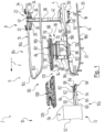
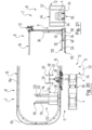
- 2 denotes a system for the surface treatment of vehicle bodies 4, of which only a transfer area 6 between a first treatment zone 8 and a second treatment zone 10 is shown.
- the first treatment zone 8 is a dip treatment zone and, in the exemplary embodiment shown here, comprises a pretreatment area and an area for cataphoretic dip painting, the dip tanks of which, however, are not specifically shown.
- the immersion treatment zone 8 thus corresponds to the treatment zone BZ1 explained at the outset. Details of a corresponding pretreatment and cataphoretic dip painting are generally known and will not be explained in more detail here.
- an outlet area 8a of the immersion treatment zone 8 is shown, to which a vehicle body 4 arrives, after crossing the corresponding plunge pools.
- the second treatment zone 10 is a drying zone, from which in the Figures 1 to 5 only an input area 10a is shown.
- the drying zone 10 thus corresponds to the treatment zone BZ2 indicated at the outset and includes a dryer 12, which will be discussed again below.
- the vehicle bodies 4 are conveyed by means of a first conveying system 14 through the first treatment zone 8 and thereby through its dip tank.
- the conveyor system 14 is an overhead conveyor in the manner of an electric monorail and includes a load-bearing drive rail 16 with an I-profile, as is also used in conventional electric monorails.
- the drive rail 16 is attached to a ceiling structure that is not specifically shown. From the drive rail 16 are in the Figures 1 to 5 respectively recognizing two opposite and parallel rectilinear portions 16a, 16b, connected to each other by a connecting portion 16c, which in turn comprises two curved portions and a rectilinear portion extending between them. The latter is only in figure 1 denoted by 16d. Below the drive rail 16 runs parallel to this a guide rail 18 with corresponding sections 18a, 18b, 18c, which is attached to bearing blocks 20 and forms a downwardly open U-profile.
- the first conveyor system 14 also includes a plurality of trolleys 22, of which in the Figures 1 to 5 only one of each is shown.
- the transport carriage 22 includes a drive carriage 24 which runs on the drive rail 16 .
- the drive carriage 24 is of a construction that is known from conventional monorail systems.
- the drive carriage 24 has two running gears 26, 28 which are connected to one another via a connecting frame 30.
- the connecting frame 30 carries, in a known manner, control components which can communicate with a central controller. In this way, a largely independent movement of the various transport carriages 22 is possible.
- the running gears 26 and 28 are equipped in a known manner with guide and support rollers, which are not specifically provided with a reference number here and roll on different surfaces of the I-shaped profile of the drive rail 16. At least one of the rollers of the chassis 26, 28 serves as a drive roller and can be rotated by an electric motor 32 or 34 for this purpose.
- the connecting frame 30 carries a support and guide profile 36 for a carriage 38, which extends vertically downwards. As a result, the support and guide profile 36 is securely guided in its vertical alignment and tilting of the support and guide profile 36 from the vertical is prevented.
- the carriage 38 is movably mounted in the support and guide profile 36 and can be moved up and down along the profile 36 by means of a servomotor 40 and associated drive components, as are known per se.
- the carriage 38 carries a connecting profile 42 which protrudes vertically downwards from the carriage 38 and parallel to the support and guide profile 36 .
- a pivot pin 46 is mounted on the end 44 of the connecting profile 42 remote from the carriage 38 and defines a horizontal axis of rotation.
- the pivot pin 46 can be rotated about the horizontal axis of rotation in both directions of rotation in a manner known per se via a geared motor carried along by the carriage 38 and not visible, which communicates with the above-mentioned control components of the transport carriage 22 .
- the pivot pin 46 is in turn rigidly connected to a support unit 48 for the vehicle body 4 so that it follows any rotary movement of the pivot pin 46 .
- a support unit 48 for the vehicle body 4 so that it follows any rotary movement of the pivot pin 46 .
- the support unit 48 includes a fastening device in the form of four locking bolts 50, which serve as coupling elements and each have a clamping cone. This works together with a respective associated coupling component of the vehicle body, which for this purpose has an engagement opening for the clamping cone.
- locking bolts are usually provided on a conveyor skid for vehicle bodies. The functioning of such locking bolts in interaction with a vehicle body is known from the prior art, so that there is no need for more detailed explanations in this regard.
- a vehicle body 4 When a vehicle body 4 is fastened to the support unit 48 via the locking bolts 50, it can be rotated through any angle, with the vehicle body 4 always remaining securely connected to the support unit 48. In this way, the vehicle body 4 can even be transported rotated by 180° with respect to the normal position with the roof down. In any case, the vehicle body 4 is conveyed by means of the overhead conveyor 14 without a skid.
- the dryer 12 includes a dryer housing 52 which defines a drying tunnel. Am in the Figures 1 to 5 An entry lock 54 is present in the entry area 10a of the dryer 12 that can be recognized. Am in the Figures 1 to 5 Not shown opposite exit end is provided in a corresponding manner an exit lock. Vehicle bodies 4 are by means of a second conveyor system 56 conveyed through the dryer housing 52.
- the second conveyor system 56 is designed as a chain conveyor in the present exemplary embodiment and comprises two essentially identical endless chains 58 which circulate parallel next to one another and are each guided by a guide profile 60 .
- the two endless chains 58 each have a conveyor strand 62 running at the top.
- the Figures 1 to 5 only the entry area of the chain conveyor 56 before it enters the dryer housing 52 can be seen.
- the dimensions and arrangement of the support bolts 64 on the endless chains 58 are adapted to the vehicle bodies 4 to be treated in such a way that they can work together with their coupling components, which are also designed for the locking bolts 50 of the first conveyor system 14 .
- the arrangement of four support bolts 64 each, two of which are guided by an endless chain 58, thus corresponds to the arrangement of the four locking bolts 50 of the support unit 48 of the first conveyor system 14.
- the support bolts 64 of the endless chains 58 only serve as support points, without the vehicle body 4 having to be firmly connected to the respective endless chain 58.
- the chain conveyor 56 also conveys the vehicle bodies 4, but without a skid.
- the dryer 12 with its chain conveyor 56 is arranged in such a way that the vehicle body 4 is conveyed by the chain conveyor 56 in the same conveying direction and also without a lateral offset, as is the case in the region of the straight section 16a of the drive rail 16 of the overhead conveyor 14.
- This conveying direction is illustrated by an arrow F.
- the transfer device 66 comprises a first roller conveyor 68 with two load-bearing roller strips 70, 72 running horizontally and parallel to one another, which are connected to one another at their respective ends via crossbeams 74.
- the roller bars 70, 72 run horizontally.
- the first roller conveyor 68 is arranged vertically between the drive rail 16 and the guide rail 18 of the overhead conveyor 14 in the region of its rectilinear section 16a of the drive rail 16 at a distance from the ground via a ceiling construction not specifically shown.
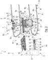
- the roller conveyor 68 is fastened in a stationary manner and is offset slightly inwards relative to the section 16a of the drive rail 16 in the direction of the parallel section 16b of the drive rail 16, so that the support and guide profile 36 with the carriage 38 and its connection profile 42 to the support unit 48 laterally can be guided past the roller conveyor 68, with the support unit 48 remaining below the roller conveyor 68, as shown in figure 2 can be seen.
- Each roller bar 70, 72 has a plurality of rollers 76, not all of which are referenced.
- the rollers 76 lie opposite one another in pairs and are each mounted such that they can rotate about a horizontal axis of rotation, which run perpendicular to the longitudinal extension of the roller strips 70, 72 and thus perpendicular to the conveying direction F.
- At least one roller 76 of an opposing pair of rollers is driven. This can be done, for example, by an electric hub motor arranged inside the driven roller 76 in each case. It is also possible for several or even all of the rollers 76 to be driven.
- a carriage 78 with a chassis 80 runs on the rollers 76 , which for this purpose comprises two parallel skid-like running rails 82 , 84 which are connected to one another via transverse bars 86 and which rest on the rollers 76 of the roller conveyor 68 .
- the rollers 76 of the roller rails 70, 72 have lateral wheel rims, which are not designated separately here.
- the running rails 84, 86 are each laterally connected to a support frame 88 of the chassis 80, which encompasses the roller rails 70, 72 of the roller conveyor 68 laterally.
- this supporting structure 88 is coupled to a horizontal supporting frame 90 of a conveyor hanger 92, which in turn carries a receiving frame 94 and 96 on the right and left in the conveying direction F.
- the mounting frames 94, 96 are spaced far enough from one another that they can accommodate a vehicle body 4 between them.
- each receiving frame 94, 96 has a support bar 98 or 100, which extends horizontally and parallel to the conveying direction F.
- Two inwardly projecting support brackets 102 and 104 are flanged to each support beam 98, 100, respectively.
- the support brackets 102 and 104 each have a support surface 102a or 104b, on which a vehicle body 4 can rest in the area of its floor longitudinal members.
- a sheet metal seam in a vehicle body in the area of its longitudinal floor members; this can be used, for example, as a storage area for the vehicle body 4, on which the support brackets 102, 104 can engage.
- a sheet metal fold offers one or more lowest points of a vehicle body 4 when it is aligned with the roof up in its normal horizontal position.
- support brackets 102, 104 can also work together with any other suitable area on the floor of the vehicle body 4 apart from the mentioned coupling components for the locking bolts 50 of the overhead conveyor 14 or support bolts 64 of the chain conveyor 56.
- the transfer device 66 includes a roller conveyor 106 that can be moved in the vertical direction.
- the movable roller conveyor 106 forms with the stationary roller conveyor a support rail system for the carriage 78.
- the movable roller conveyor 106 is arranged in the direction of the dryer 12 next to the stationary roller conveyor 68 and extends in the same longitudinal direction as this.
- the movable roller conveyor 106 On its upper side, the movable roller conveyor 106 is coupled to a lifting/lowering device 108 in the manner of a scissor lift table, which in turn is fastened to a ceiling structure that is not specifically shown.
- the lifting/lowering device 108 is designed according to standard design features, so that a more detailed explanation of this is unnecessary.
- the movable roller conveyor 106 is arranged above the entry area of the chain conveyor 56 and can be moved between an upper working position and a lower working position by means of the lifting/lowering device 108 .
- the movable roller conveyor 106 In the in the Figures 1 to 4 In the upper working position shown, the movable roller conveyor 106 is arranged at the same height as the stationary roller conveyor 68. In the upper working position, the movable roller conveyor 106 thus forms a continuation of the stationary roller conveyor 68.
- An intermediate space 110 remains between the two opposite ends of the roller conveyors 68 and 106 and is arranged in the area below the straight section 16d of the connecting section 16c of the drive rail 16 of the overhead conveyor 14 .
- This intermediate space 110 is dimensioned in such a way that the transport carriage 22 of the overhead conveyor 14 can be moved from section 16a of the drive rail 16 via the connecting section 16c to its section 16b, with the support and guide profile 36 of the transport carriage 22 being placed between the opposite ends of the two roller conveyors without colliding 68 and 106 can be passed through.
- FIG. 1 is shown as the initial situation that a vehicle body 4 is fixed by means of the locking bolt 50 to the support unit 48 of the trolley 22 of the overhead conveyor 14.
- the vehicle body 4 has undergone the above-mentioned pretreatment and cataphoretic dip painting and is now to be fed to the dryer 12 in the conveying direction F and to be transferred to its chain conveyor 56 for this purpose.
- the carriage 78 of the transfer device 66 is located in the area of the stationary roller conveyor 68 and rests with its running rails 82, 84 on its rollers 76.
- the carriage 38 of the transport carriage 22 is moved by means of the servomotor 40 into a vertical position in which the support unit 48 with the vehicle body 4 is arranged at a level above the receiving surfaces 102a, 104a of the support brackets 102, 104 of the conveyor hanger 92 of the transfer device 66.
- the transport carriage 22 is now moved in the conveying direction F until the vehicle body 4 is located between the receiving frames 94 , 96 of the carriage 78 of the transfer device 66 .
- the vehicle body 4 is positioned in the conveying direction F in such a way that the support brackets 102 and 104 come to rest below the floor areas of the vehicle body 4 assigned to them, which have been explained above.
- the carriage 38 of the transport carriage 22 is then moved downwards until the vehicle body 4 with its floor areas suitable for this purpose, as explained above, is seated on the bearing surfaces 102a, 104a of the support brackets 102, 104 of the conveying hanger 92.
- This phase is in figure 2 shown. It can be seen there that at least the support brackets 104 at the rear in the conveying direction F are then positioned laterally next to the locking bolts 50 at the rear in the conveying direction F in the direction perpendicular to the conveying direction F.
- the floor areas of the vehicle body 4, which work together with the support brackets 104 accordingly flank the coupling components of the vehicle body 4, which are intended for the locking bolts 50 of the overhead conveyor 14 and the support bolts 64 of the chain conveyor 56.
- the support brackets 102, 104 engage and work together with floor areas of the roof-up vehicle body 4 that are not used by the first conveyor system in the form of the overhead conveyor 14 or the second conveyor system in the form of the chain conveyor 56. In the present case, these floor areas are present on the sill of the vehicle body 4 .
- the coupling components of the vehicle body 4 for the locking bolts 50 of the overhead conveyor 14 and the support bolts 64 of the chain conveyor 56 are correspondingly offset in relation to the sills of the vehicle body 4 in relation to the center plane in the longitudinal direction, as is usually the case.
- the locking bolts 50 of the support unit 48 are now released and the carriage 38 of the transport carriage 22 is moved down a little so that the support unit 48 releases the vehicle body 4 and this is now completely supported by the carriage 78 of the transfer device 66.
- the movable roller conveyor 106 is brought into its upper working position by means of the lifting/lowering device 108 and the driven rollers 76 of the two roller conveyors 68, 106 are energized so that the carriage 78 together with the vehicle body 4 can be moved in the conveying direction F from the stationary roller conveyor 68 to the movable Roller conveyor 106 is moved.
- the carriage 78 is shown driving from the stationary roller conveyor 68 onto the movable roller conveyor 106.
- the runners 80, 82 of the carriage 78 of the transfer device 66 are so long that the gap 110 between the opposite ends of the two roller conveyors 68 and 106 can be bridged without risk.
- the carriage 78 After the carriage 78 has moved completely onto the movable roller conveyor 106 (see figure 4 ), the carriage 78 is brought into a position in which the coupling components of the vehicle body 4 explained above are each arranged above an associated support bolt 64 of the chain conveyor 56 which projects upwards.
- the lifting/lowering device 108 is controlled in such a way that the movable roller conveyor 106 is lowered together with the carriage 78 and the vehicle body 4 .
- the support bolts 64 engage in the respective associated coupling component of the vehicle body 4 and receive the vehicle body 4 .
- the moveable roller conveyor 106 is moved further down beyond this receiving position into a lower working position, so that the support brackets 102, 104 of the conveyor hanger 92 detach from the vehicle body 4 and this finally rests completely on the chain conveyor 56. This is in figure 5 shown.
- the vehicle body 4 can be handed over when the chain conveyor 56 is stationary.
- the transfer can also be carried out with the chain conveyor 56 running, for which purpose the carriage 78 is moved synchronously with the forward speed of the chain conveyor 56 and the vehicle body 4 is lowered at the same time.
- the vehicle body 4 is conveyed into the dryer housing 52 by means of the chain conveyor 56, where the vehicle body 4 is dried.
- the movable roller conveyor 106 can be brought back into its upper working position and the carriage 78 can be moved back onto the stationary roller conveyor 68 (see FIG figure 1 ).
- the transfer operation can then be repeated with another vehicle body 4 coming from the cataphoretic dip painting in the dip treatment zone 8.
- the transport carriage 22 of the overhead conveyor 14 can be moved between the roller conveyors 68, 106 to the section 16b of the drive rail 16 and be guided back via this to the dip tanks of the dip treatment zone 8.
- the vertical position of the conveyor hanger 92 and thus the support bracket 102, 104 can be adjusted by the movable roller conveyor 106.
- a lifting/lowering device can also be arranged between the carriage 78 and the conveyor hanger 92 .
- the second roller conveyor 106 can also be stationary and fixed in height.
- the transfer device 66 according to the first embodiment according to Figures 1 to 5 is set up especially for a transfer between two conveyor systems, in which the vehicle body 4 is conveyed in one and the same conveying direction F, without there being a change in direction or a lateral offset between the conveying directions of the two conveying systems.
- the individual local conditions can also require an arrangement of the two treatment zones 8 and 10 to be passed through one after the other, which require a change in the conveying direction F of the vehicle body 4 .
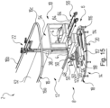
- the immersion treatment zone 8 and the drying zone 10 are not arranged one behind the other in one and the same conveying direction. Rather, the immersion treatment zone 8 and the drying zone 10 are located next to one another in such a way that the vehicle bodies 4 are conveyed with the overhead conveyor 14 in a first conveying direction F1 through the immersion treatment zone 8 and with the chain conveyor 56 in an opposite second conveying direction F2 through the dryer 12.
- the conveying directions F1 and F2 are only in the figures 6 and 7 indicated by arrows.
- the dryer housing 52 runs next to the section 18a of the guide rail 18 of the overhead conveyor 14.
- a transfer device 112 which has a Movement of a vehicle body 4 allowed perpendicular to the conveying directions F1 and F2.
- the transfer device 112 comprises a carriage 114 as a carriage, which runs on a pair of rails 116, which is used here as a support rail system and is attached to the floor.
- the pair of rails 116 is arranged between the sections 18a and 18b of the guide rail 18 and runs perpendicular to them.
- the pair of rails 116 extends below the guide rail 18 so that the carriage 114 could in principle be moved so close to the guide rail 18 that it touches it.
- the carriage 114 is driven back and forth between a front operating position in which it is moved close to the guide rail 18 and a rear operating position in which it is spaced apart from the guide rail 18 .
- the distance from the guide rail 18 is large enough for the support unit 48 of the transport carriage 22 of the overhead conveyor 14 to fit between the carriage 114 and the guide rail 18 . For example, this is in figure 6 to recognize.
- the carriage 114 comprises a support table 118 which can be raised and lowered in the vertical direction and which can be moved up and down between a lower working position and an upper working position.
- the carriage 114 carries a lifting and lowering device, not specifically shown in the figures, which can be present, for example, in the form of an eccentric lifting table or a scissor lifting table, as is known per se.
- the support table 118 in turn guides a horizontally extending support fork 120 with two parallel support tines 122, 124, each of which offers an overhead support surface 122a, 124a.
- the vertical position of the support fork 120 and thus of the support prongs 122, 124 can be adjusted by the support table 118.
- the support fork 120 can be extended and retracted horizontally in a direction towards the drying zone 10 beyond the support table 118, which is perpendicular to the conveying directions F1 and F2.
- the horizontal position of the support fork 120 relative to the carriage 114 can be adjusted.
- the transfer of a vehicle body 4 from the overhead conveyor 14 of the immersion treatment zone 8 to the chain conveyor 56 of the drying zone 10 is carried out by means of the transfer device 112 as follows.
- the figures 6 , 9 , 12 , 15 , 16 and 19 show five phases of the transfer in a perspective view, of which the first, second and third and fifth and sixth phase in the figures 7 , 10 , 13 , 17 and 20 in a plan view and in FIGS figures 8 , 11 , 14 , 18 and 21 are shown in a front view.
- FIG Figures 6 to 8 A vehicle body 4 coming from the dip tanks of the dip treatment zone 8 via the rail portion 16a is shown in FIG Figures 6 to 8 shown phase still fixed by means of the locking bolt 50 to the support unit 48 of the transport carriage 22 of the overhead conveyor 14.
- the transport carriage 22 of the overhead conveyor 14 has already been moved to a position in which the vehicle body 4 is arranged in front of the carriage 114 .
- the transport carriage has already passed through the curved section 16c of the drive rail 16 coming from the section 16a.
- the locking bolts 50 of the support unit 48 are released and the carriage 38 of the transport carriage 22 is moved down a little so that the support unit 48 releases the vehicle body 4 and this is now completely supported by the carriage 114 of the transfer device 112.
- the carrying fork 120 of the transfer device 112 is retracted so that the vehicle body 4 comes to rest over the carrying table 118 .
- the transport carriage 22 of the overhead conveyor 14 can then be moved counter to the conveying direction F1, for example, so that the area in front of the carriage 114 in the direction of the drying zone 10 becomes free. This phase of handover is in the Figures 12 to 14 shown. From here, the transport carriage 22 over the rail section 16b are returned to the dip tanks of the dip treatment zone 8.
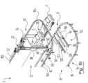
- the vehicle body 4 In the transfer position of the carriage 114, the vehicle body 4 assumes a position above the chain conveyor 56, in which its coupling components explained above are each arranged above an associated support bolt 64 of the chain conveyor 56 projecting upwards. If necessary, the support table 118 of the carriage 114 was raised somewhat compared to its initial position.
- the support table 118 is lowered together with the vehicle body 4 , the support pins 64 of the chain conveyor 56 being inserted into the respectively associated coupling component of the vehicle body 4 and receiving the vehicle body 4 .
- the support bolts 64 are so long that the support tines 122, 124 can move further down in the space between the vehicle body 4 and the endless chains 58 of the chain conveyor in order to release the vehicle body 4.
- the carrying fork 120 is retracted and the vehicle body 4 is transferred to the chain conveyor 56.
- the vehicle body 4 is then conveyed into the dryer housing 52 by means of the chain conveyor 56, where the vehicle body 4 is dried.
- the movable and moveable components of the transfer device 112 are returned to their in the Figures 6 to 8 brought to the starting positions shown, whereupon the transfer operation can be carried out again with another vehicle body 4 coming from the cataphoretic dip painting in the dip treatment zone 8.
- the transfer devices 66 and 112 explained above as the first and second exemplary embodiment were described on the basis of a respective transfer area between an immersion treatment zone and a drying zone, which corresponds to the treatment zones BZ-1 and BZ-2 explained at the outset.
- the transfer devices 66 and 112 can also be arranged in any other transfer transfer area between successive treatment zones BZ-(x) and BZ-(x+1) in which a vehicle body has to be transferred from a first conveyor system to a second conveyor system.
- the vehicle bodies 4 cannot only be transferred from one overhead conveyor to a second conveyor system. A corresponding transfer from structurally different and also different first conveyor systems to a second conveyor system is also possible.
- a vehicle body should be conveyed without a skid as far as possible during the entire passage through the treatment system 2 .
- the two conveyor systems 14 and 56 in the treatment plant 2 described above have each been explained by way of example as a variant in which the vehicle body 4 is not conveyed on a skid, as is generally the case, but directly with the corresponding conveyor system 14 or 56 is coupled.
- the transfer devices 66 and 112 can also be used to transfer vehicle bodies from a first conveyor system, in which the vehicle bodies are conveyed with a skid, to a second conveyor system, by which the vehicle bodies are transported without a skid.
- a vehicle body can also be transferred using the transfer devices 66 or 112 from a first conveyor system, from which the vehicle bodies are transported without a skid, to a second conveyor system, in which the vehicle bodies are transported with a skid.
- skids can be dispensed with at least in some areas of the treatment plant, especially in drying zones, for example, so that no additional energy is released to the skids.
Landscapes
- Engineering & Computer Science (AREA)
- Mechanical Engineering (AREA)
- Manufacturing & Machinery (AREA)
- Chemical & Material Sciences (AREA)
- Combustion & Propulsion (AREA)
- Transportation (AREA)
- Automobile Manufacture Line, Endless Track Vehicle, Trailer (AREA)
- Spray Control Apparatus (AREA)
- Intermediate Stations On Conveyors (AREA)
Applications Claiming Priority (2)
| Application Number | Priority Date | Filing Date | Title |
|---|---|---|---|
| DE102010045014A DE102010045014A1 (de) | 2010-09-10 | 2010-09-10 | Anlage zur Oberflächenbehandlung von Fahrzeugkarosserien |
| PCT/EP2011/004177 WO2012031678A1 (de) | 2010-09-10 | 2011-08-19 | Anlage zur oberflächenbehandlung von fahrzeugkarosserien |
Publications (3)
| Publication Number | Publication Date |
|---|---|
| EP2613995A1 EP2613995A1 (de) | 2013-07-17 |
| EP2613995B1 EP2613995B1 (de) | 2016-12-21 |
| EP2613995B2 true EP2613995B2 (de) | 2023-04-12 |
Family
ID=44509190
Family Applications (1)
| Application Number | Title | Priority Date | Filing Date |
|---|---|---|---|
| EP11748276.0A Active EP2613995B2 (de) | 2010-09-10 | 2011-08-19 | Anlage zur oberflächenbehandlung von fahrzeugkarosserien |
Country Status (10)
| Country | Link |
|---|---|
| US (1) | US9555974B2 (es) |
| EP (1) | EP2613995B2 (es) |
| CN (1) | CN103097232B (es) |
| BR (1) | BR112013005672A8 (es) |
| DE (1) | DE102010045014A1 (es) |
| ES (1) | ES2618901T5 (es) |
| HU (1) | HUE032206T2 (es) |
| PL (1) | PL2613995T5 (es) |
| RU (1) | RU2587743C2 (es) |
| WO (1) | WO2012031678A1 (es) |
Families Citing this family (14)
| Publication number | Priority date | Publication date | Assignee | Title |
|---|---|---|---|---|
| FR2996541B1 (fr) * | 2012-10-10 | 2015-04-17 | Renault Sa | "systeme de support et de convoyage de pieces" |
| DE102013100619A1 (de) * | 2012-12-19 | 2014-06-26 | Dr. Ing. H.C. F. Porsche Aktiengesellschaft | Transportvorrichtung |
| DE102013110362A1 (de) * | 2013-09-19 | 2015-03-19 | Dr. Ing. H.C. F. Porsche Aktiengesellschaft | Montagestation und Montage-Verfahren für Fahrzeuge |
| CN105344519A (zh) * | 2015-09-25 | 2016-02-24 | 佛山市沃顿数控设备有限公司 | 一种自动喷漆系统 |
| DE102016004484A1 (de) * | 2016-04-13 | 2017-10-19 | Eisenmann Se | Verfahren und Fertigungsanlage zur Herstellung von Fahrzeugen und Oberflächenbehandlungsanlage zur Oberflächenbehandlung von Fahrzeugkarosserien |
| JP6487398B2 (ja) * | 2016-09-14 | 2019-03-20 | 中洲電機株式会社 | 搬送装置及び搬送体 |
| DE102017000640B4 (de) | 2017-01-25 | 2018-12-20 | Audi Ag | Beschichtungsanlage und Verfahren zum Betreiben einer Beschichtungsanlage |
| DE102018123270A1 (de) * | 2018-09-21 | 2020-03-26 | Eisenmann Se | Oberflächenbehandlungsanlage und Verfahren zur Oberflächenbehandlung von Fahrzeugkarosserien |
| US11618520B2 (en) * | 2020-11-13 | 2023-04-04 | Victor Hugo Rueda | Cableway system that is used to transport occupied vehicles between a pair of transfer stations |
| CN113457897B (zh) * | 2021-07-07 | 2022-07-12 | 成都天码行空机器人研究有限公司 | 一种用于汽车零部件的连续喷涂线及使用方法 |
| US11390470B1 (en) * | 2021-12-01 | 2022-07-19 | Cooley Enterprises, LLC | Clean energy integrated transportation system |
| US11827249B2 (en) | 2021-12-01 | 2023-11-28 | Cooley Enterprises, LLC | Clean energy integrated transportation system using a hydro system |
| US11565884B1 (en) | 2021-12-01 | 2023-01-31 | Cooley Enterprises, LLC | Clean energy integrated transportation system using a track and cable |
| DE102022130201A1 (de) | 2022-11-15 | 2024-05-16 | Dürr Systems Ag | Förderanlage und Verfahren zum Behandeln von Werkstücken |
Family Cites Families (22)
| Publication number | Priority date | Publication date | Assignee | Title |
|---|---|---|---|---|
| SE373811B (es) | 1972-05-19 | 1975-02-17 | Volvo Ab | |
| JPS5791714U (es) | 1980-11-28 | 1982-06-05 | ||
| JPH0772012B2 (ja) * | 1988-10-28 | 1995-08-02 | 株式会社椿本チエイン | 物品の離隔搬送装置 |
| US5115758A (en) * | 1989-10-23 | 1992-05-26 | Mazda Motor Corporation | Coating apparatus for coating a vehicle body |
| DE4127580C1 (en) | 1991-08-21 | 1993-02-11 | Duerr Gmbh | Car body high gloss paint coating - incorporates sliding carriage and transport rotor with adaptors gripping body |
| JP2532533Y2 (ja) * | 1991-10-08 | 1997-04-16 | 三菱自動車工業株式会社 | ワーク搬送系のインターロック装置 |
| DE9207678U1 (es) * | 1992-06-05 | 1992-08-20 | Cfc-Foerdersysteme Gmbh, 7500 Karlsruhe, De | |
| JP3244932B2 (ja) | 1994-04-01 | 2002-01-07 | トリニティ工業株式会社 | コンベア装置 |
| DE19641048C2 (de) | 1996-10-04 | 2000-07-20 | Flaekt Ab | Verfahren zum Ein- und Ausbringen von Werkstücken, insbesondere Fahrzeugkarosserien, Vorrichtung und Anlage zur Oberflächenbehandlung von Werkstücken im Durchlauf |
| JP3765509B2 (ja) | 1996-12-13 | 2006-04-12 | 本田技研工業株式会社 | 自動車組立ライン及び自動車搬送方法 |
| IT246948Y1 (it) * | 1999-12-17 | 2002-04-10 | Fata Group S P A | Impianto di lavorazione con dispositivo di blocco e centratura discocche in stazioni di lavorazioni. |
| JP3775719B2 (ja) * | 2000-08-23 | 2006-05-17 | 本田技研工業株式会社 | 車体移載装置および車体移載方法 |
| US6374993B1 (en) * | 2000-09-14 | 2002-04-23 | Lico, Inc. | Carrier locking system for pendulum conveyor |
| ITMI20002824A1 (it) * | 2000-12-22 | 2002-06-22 | Geico Spa | Impianto automatico modulare per il trasporto e per il trattamento disuperfici di scocche di veicoli e similari |
| DE10121053A1 (de) * | 2001-04-28 | 2002-10-31 | Duerr Systems Gmbh | Fördervorrichtung zum Fördern von Werkstücken durch einen Behandlungsbereich zur Oberflächenbehandlung der Werkstücke |
| DE10200982B4 (de) * | 2002-01-12 | 2004-01-29 | Dr.Ing.H.C. F. Porsche Ag | Transporteinrichtung |
| DK1478564T3 (da) | 2002-02-20 | 2007-07-23 | Duerr Systems Gmbh | Apparat og fremgangsmåde til behandling af emner, især köretöjkarrosserier |
| EP1340709B1 (de) | 2002-07-03 | 2005-04-06 | TMS Produktionssysteme GmbH | Transportanlage zum Transport von Bauteilen |
| JP4336161B2 (ja) * | 2003-08-11 | 2009-09-30 | 本田技研工業株式会社 | 車体の移載装置 |
| JP4092324B2 (ja) * | 2004-10-28 | 2008-05-28 | 本田技研工業株式会社 | 自動車車体移載方法及び移載装置 |
| JP4453626B2 (ja) * | 2005-07-25 | 2010-04-21 | 株式会社ダイフク | 搬送設備 |
| JP4978371B2 (ja) * | 2007-08-24 | 2012-07-18 | 株式会社ダイフク | 台車利用の搬送装置 |
-
2010
- 2010-09-10 DE DE102010045014A patent/DE102010045014A1/de not_active Withdrawn
-
2011
- 2011-08-19 EP EP11748276.0A patent/EP2613995B2/de active Active
- 2011-08-19 US US13/821,878 patent/US9555974B2/en active Active
- 2011-08-19 RU RU2013115836/11A patent/RU2587743C2/ru active
- 2011-08-19 BR BR112013005672A patent/BR112013005672A8/pt active Search and Examination
- 2011-08-19 HU HUE11748276A patent/HUE032206T2/hu unknown
- 2011-08-19 ES ES11748276T patent/ES2618901T5/es active Active
- 2011-08-19 CN CN201180043311.0A patent/CN103097232B/zh active Active
- 2011-08-19 WO PCT/EP2011/004177 patent/WO2012031678A1/de active Application Filing
- 2011-08-19 PL PL11748276.0T patent/PL2613995T5/pl unknown
Also Published As
| Publication number | Publication date |
|---|---|
| BR112013005672A2 (pt) | 2016-05-03 |
| WO2012031678A1 (de) | 2012-03-15 |
| EP2613995B1 (de) | 2016-12-21 |
| EP2613995A1 (de) | 2013-07-17 |
| RU2587743C2 (ru) | 2016-06-20 |
| PL2613995T3 (pl) | 2017-07-31 |
| BR112013005672A8 (pt) | 2017-10-10 |
| RU2013115836A (ru) | 2014-10-20 |
| ES2618901T5 (es) | 2023-06-19 |
| US20130319822A1 (en) | 2013-12-05 |
| CN103097232B (zh) | 2015-11-25 |
| US9555974B2 (en) | 2017-01-31 |
| DE102010045014A1 (de) | 2012-03-15 |
| PL2613995T5 (pl) | 2023-10-02 |
| CN103097232A (zh) | 2013-05-08 |
| ES2618901T3 (es) | 2017-06-22 |
| HUE032206T2 (hu) | 2017-09-28 |
Similar Documents
| Publication | Publication Date | Title |
|---|---|---|
| EP2613995B2 (de) | Anlage zur oberflächenbehandlung von fahrzeugkarosserien | |
| EP2242712B1 (de) | Hängebahnsystem und tauchbehandlungsanlage mit einem solchen | |
| EP1383696B1 (de) | Fördervorrichtung zum fördern von werkstücken durch einen behandlungsbereich zur oberflächenbehandlung der werkstücke | |
| EP2322414B1 (de) | Antriebseinheit, Antriebssystem und Förderanlage für Skids | |
| EP2231492B1 (de) | Tauchbehandlungsanlage | |
| EP2613997B1 (de) | Fördereinheit und fördersystem zum fördern von fahrzeugkarosserien sowie anlage zur behandlung von farhzeugkarosserien | |
| EP1059225B1 (de) | Verfahren und Fördervorrichtung zum Fördern von Fahrzeugkarosserien durch ein Behandlungsbad | |
| EP2714496B1 (de) | Vorrichtung zum fördern und anlage zur oberflächenbehandlung von gegenständen | |
| EP1931580B1 (de) | Rollenbahnförderer | |
| EP2242711B2 (de) | Hängebahnsystem, tauchbehandlungsanlage mit einem solchen, und verwendung dieses hängebahnsystems | |
| DE102016004484A1 (de) | Verfahren und Fertigungsanlage zur Herstellung von Fahrzeugen und Oberflächenbehandlungsanlage zur Oberflächenbehandlung von Fahrzeugkarosserien | |
| EP1747156A1 (de) | Anlage und verfahren zum befördern von werkstücken entlang einer behandlungsstrecke | |
| EP3526534B1 (de) | Temperiervorrichtung, oberflächenbehandlungsanlage, fertigungsanlage und verfahren zur herstellung von produkten | |
| DE10210942B4 (de) | Anlage zum Behandeln, insbesondere zum kataphoretischen Tauchlackieren, von Gegenständen, insbesondere von Fahrzeugkarosserien | |
| EP2484607B1 (de) | Tragbahnförderer und Förderanlage mit einem solchen | |
| DE10211214C1 (de) | Anlage zum Behandeln, insbesondere zum kataphoretischen Tauchlackieren, von Gegenständen, insbesondere von Fahrzeugkarosserien | |
| DE10328555A1 (de) | Vorrichtung zum Ausschleusen von Lastträgern | |
| EP1059223A1 (de) | Skidrahmen zum Fördern von Werkstücken, insbesondere von Fahrzeugkarosserien, und Drehvorrichtung zum Drehen eines solchen Skidrahmens | |
| EP2707267B1 (de) | Spindelförderer und anlage zum behandeln von werkstücken mit einem solchen |
Legal Events
| Date | Code | Title | Description |
|---|---|---|---|
| PUAI | Public reference made under article 153(3) epc to a published international application that has entered the european phase |
Free format text: ORIGINAL CODE: 0009012 |
|
| 17P | Request for examination filed |
Effective date: 20130405 |
|
| AK | Designated contracting states |
Kind code of ref document: A1 Designated state(s): AL AT BE BG CH CY CZ DE DK EE ES FI FR GB GR HR HU IE IS IT LI LT LU LV MC MK MT NL NO PL PT RO RS SE SI SK SM TR |
|
| RIN1 | Information on inventor provided before grant (corrected) |
Inventor name: HENNIG, THOMAS Inventor name: ROBBIN, JOERG Inventor name: HANF, JUERGEN |
|
| DAX | Request for extension of the european patent (deleted) | ||
| RAP1 | Party data changed (applicant data changed or rights of an application transferred) |
Owner name: EISENMANN SE |
|
| 17Q | First examination report despatched |
Effective date: 20151111 |
|
| GRAP | Despatch of communication of intention to grant a patent |
Free format text: ORIGINAL CODE: EPIDOSNIGR1 |
|
| INTG | Intention to grant announced |
Effective date: 20160712 |
|
| GRAS | Grant fee paid |
Free format text: ORIGINAL CODE: EPIDOSNIGR3 |
|
| STAA | Information on the status of an ep patent application or granted ep patent |
Free format text: STATUS: GRANT OF PATENT IS INTENDED |
|
| GRAA | (expected) grant |
Free format text: ORIGINAL CODE: 0009210 |
|
| STAA | Information on the status of an ep patent application or granted ep patent |
Free format text: STATUS: THE PATENT HAS BEEN GRANTED |
|
| AK | Designated contracting states |
Kind code of ref document: B1 Designated state(s): AL AT BE BG CH CY CZ DE DK EE ES FI FR GB GR HR HU IE IS IT LI LT LU LV MC MK MT NL NO PL PT RO RS SE SI SK SM TR |
|
| REG | Reference to a national code |
Ref country code: GB Ref legal event code: FG4D Free format text: NOT ENGLISH |
|
| REG | Reference to a national code |
Ref country code: CH Ref legal event code: EP |
|
| REG | Reference to a national code |
Ref country code: IE Ref legal event code: FG4D Free format text: LANGUAGE OF EP DOCUMENT: GERMAN |
|
| REG | Reference to a national code |
Ref country code: AT Ref legal event code: REF Ref document number: 855203 Country of ref document: AT Kind code of ref document: T Effective date: 20170115 |
|
| REG | Reference to a national code |
Ref country code: DE Ref legal event code: R096 Ref document number: 502011011391 Country of ref document: DE |
|
| PG25 | Lapsed in a contracting state [announced via postgrant information from national office to epo] |
Ref country code: LV Free format text: LAPSE BECAUSE OF FAILURE TO SUBMIT A TRANSLATION OF THE DESCRIPTION OR TO PAY THE FEE WITHIN THE PRESCRIBED TIME-LIMIT Effective date: 20161221 |
|
| REG | Reference to a national code |
Ref country code: LT Ref legal event code: MG4D |
|
| REG | Reference to a national code |
Ref country code: NL Ref legal event code: MP Effective date: 20161221 |
|
| PG25 | Lapsed in a contracting state [announced via postgrant information from national office to epo] |
Ref country code: SE Free format text: LAPSE BECAUSE OF FAILURE TO SUBMIT A TRANSLATION OF THE DESCRIPTION OR TO PAY THE FEE WITHIN THE PRESCRIBED TIME-LIMIT Effective date: 20161221 Ref country code: LT Free format text: LAPSE BECAUSE OF FAILURE TO SUBMIT A TRANSLATION OF THE DESCRIPTION OR TO PAY THE FEE WITHIN THE PRESCRIBED TIME-LIMIT Effective date: 20161221 Ref country code: NO Free format text: LAPSE BECAUSE OF FAILURE TO SUBMIT A TRANSLATION OF THE DESCRIPTION OR TO PAY THE FEE WITHIN THE PRESCRIBED TIME-LIMIT Effective date: 20170321 Ref country code: GR Free format text: LAPSE BECAUSE OF FAILURE TO SUBMIT A TRANSLATION OF THE DESCRIPTION OR TO PAY THE FEE WITHIN THE PRESCRIBED TIME-LIMIT Effective date: 20170322 |
|
| PG25 | Lapsed in a contracting state [announced via postgrant information from national office to epo] |
Ref country code: HR Free format text: LAPSE BECAUSE OF FAILURE TO SUBMIT A TRANSLATION OF THE DESCRIPTION OR TO PAY THE FEE WITHIN THE PRESCRIBED TIME-LIMIT Effective date: 20161221 Ref country code: RS Free format text: LAPSE BECAUSE OF FAILURE TO SUBMIT A TRANSLATION OF THE DESCRIPTION OR TO PAY THE FEE WITHIN THE PRESCRIBED TIME-LIMIT Effective date: 20161221 Ref country code: FI Free format text: LAPSE BECAUSE OF FAILURE TO SUBMIT A TRANSLATION OF THE DESCRIPTION OR TO PAY THE FEE WITHIN THE PRESCRIBED TIME-LIMIT Effective date: 20161221 |
|
| REG | Reference to a national code |
Ref country code: ES Ref legal event code: FG2A Ref document number: 2618901 Country of ref document: ES Kind code of ref document: T3 Effective date: 20170622 |
|
| PG25 | Lapsed in a contracting state [announced via postgrant information from national office to epo] |
Ref country code: NL Free format text: LAPSE BECAUSE OF FAILURE TO SUBMIT A TRANSLATION OF THE DESCRIPTION OR TO PAY THE FEE WITHIN THE PRESCRIBED TIME-LIMIT Effective date: 20161221 |
|
| PG25 | Lapsed in a contracting state [announced via postgrant information from national office to epo] |
Ref country code: IS Free format text: LAPSE BECAUSE OF FAILURE TO SUBMIT A TRANSLATION OF THE DESCRIPTION OR TO PAY THE FEE WITHIN THE PRESCRIBED TIME-LIMIT Effective date: 20170421 Ref country code: RO Free format text: LAPSE BECAUSE OF FAILURE TO SUBMIT A TRANSLATION OF THE DESCRIPTION OR TO PAY THE FEE WITHIN THE PRESCRIBED TIME-LIMIT Effective date: 20161221 Ref country code: SK Free format text: LAPSE BECAUSE OF FAILURE TO SUBMIT A TRANSLATION OF THE DESCRIPTION OR TO PAY THE FEE WITHIN THE PRESCRIBED TIME-LIMIT Effective date: 20161221 Ref country code: EE Free format text: LAPSE BECAUSE OF FAILURE TO SUBMIT A TRANSLATION OF THE DESCRIPTION OR TO PAY THE FEE WITHIN THE PRESCRIBED TIME-LIMIT Effective date: 20161221 |
|
| REG | Reference to a national code |
Ref country code: FR Ref legal event code: PLFP Year of fee payment: 7 |
|
| PG25 | Lapsed in a contracting state [announced via postgrant information from national office to epo] |
Ref country code: SM Free format text: LAPSE BECAUSE OF FAILURE TO SUBMIT A TRANSLATION OF THE DESCRIPTION OR TO PAY THE FEE WITHIN THE PRESCRIBED TIME-LIMIT Effective date: 20161221 Ref country code: PT Free format text: LAPSE BECAUSE OF FAILURE TO SUBMIT A TRANSLATION OF THE DESCRIPTION OR TO PAY THE FEE WITHIN THE PRESCRIBED TIME-LIMIT Effective date: 20170421 Ref country code: BG Free format text: LAPSE BECAUSE OF FAILURE TO SUBMIT A TRANSLATION OF THE DESCRIPTION OR TO PAY THE FEE WITHIN THE PRESCRIBED TIME-LIMIT Effective date: 20170321 |
|
| REG | Reference to a national code |
Ref country code: DE Ref legal event code: R026 Ref document number: 502011011391 Country of ref document: DE |
|
| REG | Reference to a national code |
Ref country code: HU Ref legal event code: AG4A Ref document number: E032206 Country of ref document: HU |
|
| PLBI | Opposition filed |
Free format text: ORIGINAL CODE: 0009260 |
|
| PLAX | Notice of opposition and request to file observation + time limit sent |
Free format text: ORIGINAL CODE: EPIDOSNOBS2 |
|
| 26 | Opposition filed |
Opponent name: DUERR SYSTEMS AG Effective date: 20170920 |
|
| PG25 | Lapsed in a contracting state [announced via postgrant information from national office to epo] |
Ref country code: DK Free format text: LAPSE BECAUSE OF FAILURE TO SUBMIT A TRANSLATION OF THE DESCRIPTION OR TO PAY THE FEE WITHIN THE PRESCRIBED TIME-LIMIT Effective date: 20161221 |
|
| PG25 | Lapsed in a contracting state [announced via postgrant information from national office to epo] |
Ref country code: SI Free format text: LAPSE BECAUSE OF FAILURE TO SUBMIT A TRANSLATION OF THE DESCRIPTION OR TO PAY THE FEE WITHIN THE PRESCRIBED TIME-LIMIT Effective date: 20161221 |
|
| PLBB | Reply of patent proprietor to notice(s) of opposition received |
Free format text: ORIGINAL CODE: EPIDOSNOBS3 |
|
| REG | Reference to a national code |
Ref country code: CH Ref legal event code: PL |
|
| PG25 | Lapsed in a contracting state [announced via postgrant information from national office to epo] |
Ref country code: MC Free format text: LAPSE BECAUSE OF FAILURE TO SUBMIT A TRANSLATION OF THE DESCRIPTION OR TO PAY THE FEE WITHIN THE PRESCRIBED TIME-LIMIT Effective date: 20161221 |
|
| GBPC | Gb: european patent ceased through non-payment of renewal fee |
Effective date: 20170819 |
|
| PG25 | Lapsed in a contracting state [announced via postgrant information from national office to epo] |
Ref country code: LI Free format text: LAPSE BECAUSE OF NON-PAYMENT OF DUE FEES Effective date: 20170831 Ref country code: CH Free format text: LAPSE BECAUSE OF NON-PAYMENT OF DUE FEES Effective date: 20170831 |
|
| REG | Reference to a national code |
Ref country code: IE Ref legal event code: MM4A |
|
| REG | Reference to a national code |
Ref country code: BE Ref legal event code: MM Effective date: 20170831 |
|
| PG25 | Lapsed in a contracting state [announced via postgrant information from national office to epo] |
Ref country code: LU Free format text: LAPSE BECAUSE OF NON-PAYMENT OF DUE FEES Effective date: 20170819 |
|
| PG25 | Lapsed in a contracting state [announced via postgrant information from national office to epo] |
Ref country code: GB Free format text: LAPSE BECAUSE OF NON-PAYMENT OF DUE FEES Effective date: 20170819 Ref country code: IE Free format text: LAPSE BECAUSE OF NON-PAYMENT OF DUE FEES Effective date: 20170819 |
|
| REG | Reference to a national code |
Ref country code: FR Ref legal event code: PLFP Year of fee payment: 8 |
|
| PG25 | Lapsed in a contracting state [announced via postgrant information from national office to epo] |
Ref country code: BE Free format text: LAPSE BECAUSE OF NON-PAYMENT OF DUE FEES Effective date: 20170831 |
|
| PG25 | Lapsed in a contracting state [announced via postgrant information from national office to epo] |
Ref country code: MT Free format text: LAPSE BECAUSE OF FAILURE TO SUBMIT A TRANSLATION OF THE DESCRIPTION OR TO PAY THE FEE WITHIN THE PRESCRIBED TIME-LIMIT Effective date: 20161221 |
|
| REG | Reference to a national code |
Ref country code: AT Ref legal event code: MM01 Ref document number: 855203 Country of ref document: AT Kind code of ref document: T Effective date: 20170819 |
|
| PG25 | Lapsed in a contracting state [announced via postgrant information from national office to epo] |
Ref country code: AT Free format text: LAPSE BECAUSE OF NON-PAYMENT OF DUE FEES Effective date: 20170819 |
|
| 29U | Proceedings interrupted after grant according to rule 142 epc |
Effective date: 20190731 |
|
| PG25 | Lapsed in a contracting state [announced via postgrant information from national office to epo] |
Ref country code: CY Free format text: LAPSE BECAUSE OF NON-PAYMENT OF DUE FEES Effective date: 20161221 |
|
| PG25 | Lapsed in a contracting state [announced via postgrant information from national office to epo] |
Ref country code: MK Free format text: LAPSE BECAUSE OF FAILURE TO SUBMIT A TRANSLATION OF THE DESCRIPTION OR TO PAY THE FEE WITHIN THE PRESCRIBED TIME-LIMIT Effective date: 20161221 |
|
| 29W | Proceedings resumed after grant [after interruption of proceedings according to rule 142 epc] |
Effective date: 20200803 |
|
| PG25 | Lapsed in a contracting state [announced via postgrant information from national office to epo] |
Ref country code: TR Free format text: LAPSE BECAUSE OF FAILURE TO SUBMIT A TRANSLATION OF THE DESCRIPTION OR TO PAY THE FEE WITHIN THE PRESCRIBED TIME-LIMIT Effective date: 20161221 |
|
| PG25 | Lapsed in a contracting state [announced via postgrant information from national office to epo] |
Ref country code: AL Free format text: LAPSE BECAUSE OF FAILURE TO SUBMIT A TRANSLATION OF THE DESCRIPTION OR TO PAY THE FEE WITHIN THE PRESCRIBED TIME-LIMIT Effective date: 20161221 |
|
| REG | Reference to a national code |
Ref country code: FR Ref legal event code: PLFP Year of fee payment: 10 |
|
| PGFP | Annual fee paid to national office [announced via postgrant information from national office to epo] |
Ref country code: FR Payment date: 20200821 Year of fee payment: 10 |
|
| APBM | Appeal reference recorded |
Free format text: ORIGINAL CODE: EPIDOSNREFNO |
|
| APBP | Date of receipt of notice of appeal recorded |
Free format text: ORIGINAL CODE: EPIDOSNNOA2O |
|
| APAH | Appeal reference modified |
Free format text: ORIGINAL CODE: EPIDOSCREFNO |
|
| RAP2 | Party data changed (patent owner data changed or rights of a patent transferred) |
Owner name: EISENMANN GMBH |
|
| APBQ | Date of receipt of statement of grounds of appeal recorded |
Free format text: ORIGINAL CODE: EPIDOSNNOA3O |
|
| PLAB | Opposition data, opponent's data or that of the opponent's representative modified |
Free format text: ORIGINAL CODE: 0009299OPPO |
|
| R26 | Opposition filed (corrected) |
Opponent name: DUERR SYSTEMS AG Effective date: 20170920 |
|
| PG25 | Lapsed in a contracting state [announced via postgrant information from national office to epo] |
Ref country code: FR Free format text: LAPSE BECAUSE OF NON-PAYMENT OF DUE FEES Effective date: 20210831 |
|
| APBU | Appeal procedure closed |
Free format text: ORIGINAL CODE: EPIDOSNNOA9O |
|
| PLAB | Opposition data, opponent's data or that of the opponent's representative modified |
Free format text: ORIGINAL CODE: 0009299OPPO |
|
| R26 | Opposition filed (corrected) |
Opponent name: DUERR SYSTEMS AG Effective date: 20170920 |
|
| PUAH | Patent maintained in amended form |
Free format text: ORIGINAL CODE: 0009272 |
|
| STAA | Information on the status of an ep patent application or granted ep patent |
Free format text: STATUS: PATENT MAINTAINED AS AMENDED |
|
| 27A | Patent maintained in amended form |
Effective date: 20230412 |
|
| AK | Designated contracting states |
Kind code of ref document: B2 Designated state(s): AL AT BE BG CH CY CZ DE DK EE ES FI FR GB GR HR HU IE IS IT LI LT LU LV MC MK MT NL NO PL PT RO RS SE SI SK SM TR |
|
| REG | Reference to a national code |
Ref country code: DE Ref legal event code: R102 Ref document number: 502011011391 Country of ref document: DE |
|
| REG | Reference to a national code |
Ref country code: ES Ref legal event code: DC2A Ref document number: 2618901 Country of ref document: ES Kind code of ref document: T5 Effective date: 20230619 |
|
| P01 | Opt-out of the competence of the unified patent court (upc) registered |
Effective date: 20230529 |
|
| REG | Reference to a national code |
Ref country code: HU Ref legal event code: GB9C Owner name: EISENMANN GMBH, DE Free format text: FORMER OWNER(S): EISENMANN SE, DE Ref country code: HU Ref legal event code: FH1C |
|
| PGFP | Annual fee paid to national office [announced via postgrant information from national office to epo] |
Ref country code: IT Payment date: 20230831 Year of fee payment: 13 Ref country code: ES Payment date: 20230918 Year of fee payment: 13 Ref country code: CZ Payment date: 20230804 Year of fee payment: 13 |
|
| PGFP | Annual fee paid to national office [announced via postgrant information from national office to epo] |
Ref country code: HU Payment date: 20230811 Year of fee payment: 13 Ref country code: DE Payment date: 20230816 Year of fee payment: 13 |
|
| PGFP | Annual fee paid to national office [announced via postgrant information from national office to epo] |
Ref country code: PL Payment date: 20230721 Year of fee payment: 13 |