EP2613903B1 - Bore cutting tool and method of making the same - Google Patents
Bore cutting tool and method of making the same Download PDFInfo
- Publication number
- EP2613903B1 EP2613903B1 EP11757397.2A EP11757397A EP2613903B1 EP 2613903 B1 EP2613903 B1 EP 2613903B1 EP 11757397 A EP11757397 A EP 11757397A EP 2613903 B1 EP2613903 B1 EP 2613903B1
- Authority
- EP
- European Patent Office
- Prior art keywords
- tool
- pits
- coating
- bore cutting
- cutting tool
- Prior art date
- Legal status (The legal status is an assumption and is not a legal conclusion. Google has not performed a legal analysis and makes no representation as to the accuracy of the status listed.)
- Active
Links
- 238000005520 cutting process Methods 0.000 title claims description 46
- 238000004519 manufacturing process Methods 0.000 title claims description 5
- 238000000576 coating method Methods 0.000 claims description 59
- 239000011248 coating agent Substances 0.000 claims description 55
- 239000000758 substrate Substances 0.000 claims description 25
- 238000000034 method Methods 0.000 claims description 15
- 229910010037 TiAlN Inorganic materials 0.000 claims description 10
- 238000010329 laser etching Methods 0.000 claims description 8
- 238000003754 machining Methods 0.000 claims description 7
- 238000010894 electron beam technology Methods 0.000 claims description 4
- 238000005530 etching Methods 0.000 claims 2
- 238000005461 lubrication Methods 0.000 description 16
- 239000000314 lubricant Substances 0.000 description 11
- 239000000463 material Substances 0.000 description 9
- 239000002184 metal Substances 0.000 description 8
- 229910052751 metal Inorganic materials 0.000 description 8
- 230000000052 comparative effect Effects 0.000 description 7
- 238000012360 testing method Methods 0.000 description 7
- 239000010936 titanium Substances 0.000 description 7
- 238000004458 analytical method Methods 0.000 description 6
- 239000010408 film Substances 0.000 description 6
- 230000009467 reduction Effects 0.000 description 6
- 238000005305 interferometry Methods 0.000 description 5
- 238000005259 measurement Methods 0.000 description 5
- 239000012530 fluid Substances 0.000 description 4
- 239000000523 sample Substances 0.000 description 4
- 239000002826 coolant Substances 0.000 description 3
- 238000000151 deposition Methods 0.000 description 3
- 150000004767 nitrides Chemical class 0.000 description 3
- 229910000997 High-speed steel Inorganic materials 0.000 description 2
- 230000008901 benefit Effects 0.000 description 2
- 238000005229 chemical vapour deposition Methods 0.000 description 2
- 238000004140 cleaning Methods 0.000 description 2
- 230000008021 deposition Effects 0.000 description 2
- 229910003460 diamond Inorganic materials 0.000 description 2
- 239000010432 diamond Substances 0.000 description 2
- 238000005553 drilling Methods 0.000 description 2
- 230000000694 effects Effects 0.000 description 2
- 230000020169 heat generation Effects 0.000 description 2
- 239000007788 liquid Substances 0.000 description 2
- 230000001050 lubricating effect Effects 0.000 description 2
- 238000012544 monitoring process Methods 0.000 description 2
- 230000035515 penetration Effects 0.000 description 2
- 238000005240 physical vapour deposition Methods 0.000 description 2
- 230000000717 retained effect Effects 0.000 description 2
- 238000001878 scanning electron micrograph Methods 0.000 description 2
- UONOETXJSWQNOL-UHFFFAOYSA-N tungsten carbide Chemical group [W+]#[C-] UONOETXJSWQNOL-UHFFFAOYSA-N 0.000 description 2
- 229910000851 Alloy steel Inorganic materials 0.000 description 1
- OKTJSMMVPCPJKN-UHFFFAOYSA-N Carbon Chemical compound [C] OKTJSMMVPCPJKN-UHFFFAOYSA-N 0.000 description 1
- 101100172748 Mus musculus Ethe1 gene Proteins 0.000 description 1
- 229910052581 Si3N4 Inorganic materials 0.000 description 1
- 229910001069 Ti alloy Inorganic materials 0.000 description 1
- ATJFFYVFTNAWJD-UHFFFAOYSA-N Tin Chemical compound [Sn] ATJFFYVFTNAWJD-UHFFFAOYSA-N 0.000 description 1
- 229910052799 carbon Inorganic materials 0.000 description 1
- 239000000919 ceramic Substances 0.000 description 1
- 238000002485 combustion reaction Methods 0.000 description 1
- 239000013065 commercial product Substances 0.000 description 1
- 239000002131 composite material Substances 0.000 description 1
- 238000005336 cracking Methods 0.000 description 1
- 238000013461 design Methods 0.000 description 1
- 230000007613 environmental effect Effects 0.000 description 1
- 238000002474 experimental method Methods 0.000 description 1
- 238000003384 imaging method Methods 0.000 description 1
- 229910044991 metal oxide Inorganic materials 0.000 description 1
- 150000004706 metal oxides Chemical class 0.000 description 1
- 150000002739 metals Chemical class 0.000 description 1
- 238000005555 metalworking Methods 0.000 description 1
- 239000011148 porous material Substances 0.000 description 1
- 230000002028 premature Effects 0.000 description 1
- 230000002035 prolonged effect Effects 0.000 description 1
- 238000004626 scanning electron microscopy Methods 0.000 description 1
- HQVNEWCFYHHQES-UHFFFAOYSA-N silicon nitride Chemical compound N12[Si]34N5[Si]62N3[Si]51N64 HQVNEWCFYHHQES-UHFFFAOYSA-N 0.000 description 1
- 239000010409 thin film Substances 0.000 description 1
- 230000007704 transition Effects 0.000 description 1
- 238000001771 vacuum deposition Methods 0.000 description 1
- 239000002699 waste material Substances 0.000 description 1
Images


Classifications
-
- B—PERFORMING OPERATIONS; TRANSPORTING
- B23—MACHINE TOOLS; METAL-WORKING NOT OTHERWISE PROVIDED FOR
- B23B—TURNING; BORING
- B23B27/00—Tools for turning or boring machines; Tools of a similar kind in general; Accessories therefor
- B23B27/14—Cutting tools of which the bits or tips or cutting inserts are of special material
-
- B—PERFORMING OPERATIONS; TRANSPORTING
- B23—MACHINE TOOLS; METAL-WORKING NOT OTHERWISE PROVIDED FOR
- B23B—TURNING; BORING
- B23B27/00—Tools for turning or boring machines; Tools of a similar kind in general; Accessories therefor
- B23B27/10—Cutting tools with special provision for cooling
-
- B—PERFORMING OPERATIONS; TRANSPORTING
- B23—MACHINE TOOLS; METAL-WORKING NOT OTHERWISE PROVIDED FOR
- B23B—TURNING; BORING
- B23B51/00—Tools for drilling machines
- B23B51/02—Twist drills
-
- B—PERFORMING OPERATIONS; TRANSPORTING
- B23—MACHINE TOOLS; METAL-WORKING NOT OTHERWISE PROVIDED FOR
- B23B—TURNING; BORING
- B23B51/00—Tools for drilling machines
- B23B51/06—Drills with lubricating or cooling equipment
-
- B—PERFORMING OPERATIONS; TRANSPORTING
- B23—MACHINE TOOLS; METAL-WORKING NOT OTHERWISE PROVIDED FOR
- B23C—MILLING
- B23C5/00—Milling-cutters
- B23C5/28—Features relating to lubricating or cooling
-
- B—PERFORMING OPERATIONS; TRANSPORTING
- B23—MACHINE TOOLS; METAL-WORKING NOT OTHERWISE PROVIDED FOR
- B23P—METAL-WORKING NOT OTHERWISE PROVIDED FOR; COMBINED OPERATIONS; UNIVERSAL MACHINE TOOLS
- B23P15/00—Making specific metal objects by operations not covered by a single other subclass or a group in this subclass
- B23P15/28—Making specific metal objects by operations not covered by a single other subclass or a group in this subclass cutting tools
- B23P15/32—Making specific metal objects by operations not covered by a single other subclass or a group in this subclass cutting tools twist-drills
-
- C—CHEMISTRY; METALLURGY
- C23—COATING METALLIC MATERIAL; COATING MATERIAL WITH METALLIC MATERIAL; CHEMICAL SURFACE TREATMENT; DIFFUSION TREATMENT OF METALLIC MATERIAL; COATING BY VACUUM EVAPORATION, BY SPUTTERING, BY ION IMPLANTATION OR BY CHEMICAL VAPOUR DEPOSITION, IN GENERAL; INHIBITING CORROSION OF METALLIC MATERIAL OR INCRUSTATION IN GENERAL
- C23C—COATING METALLIC MATERIAL; COATING MATERIAL WITH METALLIC MATERIAL; SURFACE TREATMENT OF METALLIC MATERIAL BY DIFFUSION INTO THE SURFACE, BY CHEMICAL CONVERSION OR SUBSTITUTION; COATING BY VACUUM EVAPORATION, BY SPUTTERING, BY ION IMPLANTATION OR BY CHEMICAL VAPOUR DEPOSITION, IN GENERAL
- C23C30/00—Coating with metallic material characterised only by the composition of the metallic material, i.e. not characterised by the coating process
- C23C30/005—Coating with metallic material characterised only by the composition of the metallic material, i.e. not characterised by the coating process on hard metal substrates
-
- B—PERFORMING OPERATIONS; TRANSPORTING
- B23—MACHINE TOOLS; METAL-WORKING NOT OTHERWISE PROVIDED FOR
- B23B—TURNING; BORING
- B23B2228/00—Properties of materials of tools or workpieces, materials of tools or workpieces applied in a specific manner
- B23B2228/10—Coatings
-
- B—PERFORMING OPERATIONS; TRANSPORTING
- B23—MACHINE TOOLS; METAL-WORKING NOT OTHERWISE PROVIDED FOR
- B23B—TURNING; BORING
- B23B2260/00—Details of constructional elements
- B23B2260/072—Grooves
-
- B—PERFORMING OPERATIONS; TRANSPORTING
- B23—MACHINE TOOLS; METAL-WORKING NOT OTHERWISE PROVIDED FOR
- B23B—TURNING; BORING
- B23B2260/00—Details of constructional elements
- B23B2260/092—Lasers
-
- Y—GENERAL TAGGING OF NEW TECHNOLOGICAL DEVELOPMENTS; GENERAL TAGGING OF CROSS-SECTIONAL TECHNOLOGIES SPANNING OVER SEVERAL SECTIONS OF THE IPC; TECHNICAL SUBJECTS COVERED BY FORMER USPC CROSS-REFERENCE ART COLLECTIONS [XRACs] AND DIGESTS
- Y10—TECHNICAL SUBJECTS COVERED BY FORMER USPC
- Y10T—TECHNICAL SUBJECTS COVERED BY FORMER US CLASSIFICATION
- Y10T29/00—Metal working
- Y10T29/49—Method of mechanical manufacture
- Y10T29/4998—Combined manufacture including applying or shaping of fluent material
- Y10T29/49982—Coating
- Y10T29/49986—Subsequent to metal working
-
- Y—GENERAL TAGGING OF NEW TECHNOLOGICAL DEVELOPMENTS; GENERAL TAGGING OF CROSS-SECTIONAL TECHNOLOGIES SPANNING OVER SEVERAL SECTIONS OF THE IPC; TECHNICAL SUBJECTS COVERED BY FORMER USPC CROSS-REFERENCE ART COLLECTIONS [XRACs] AND DIGESTS
- Y10—TECHNICAL SUBJECTS COVERED BY FORMER USPC
- Y10T—TECHNICAL SUBJECTS COVERED BY FORMER US CLASSIFICATION
- Y10T408/00—Cutting by use of rotating axially moving tool
- Y10T408/78—Tool of specific diverse material
-
- Y—GENERAL TAGGING OF NEW TECHNOLOGICAL DEVELOPMENTS; GENERAL TAGGING OF CROSS-SECTIONAL TECHNOLOGIES SPANNING OVER SEVERAL SECTIONS OF THE IPC; TECHNICAL SUBJECTS COVERED BY FORMER USPC CROSS-REFERENCE ART COLLECTIONS [XRACs] AND DIGESTS
- Y10—TECHNICAL SUBJECTS COVERED BY FORMER USPC
- Y10T—TECHNICAL SUBJECTS COVERED BY FORMER US CLASSIFICATION
- Y10T408/00—Cutting by use of rotating axially moving tool
- Y10T408/89—Tool or Tool with support
Definitions
- the present invention relates to a bore cutting tool according to the preamble of claim 1, an example bing known from FR2801234A1 , and method of making a bore cutting tool according to the preamble of claim 10 in particular such bore cutting tools for metal workpieces, and in particular twist drills.
- lubrication also referred to as coolant
- Hydrodynamic lubrication where two sliding surfaces are separated by a film of liquid which is held between them by local pressure
- elastohydrodynamic lubrication where two sliding surfaces are separated by a very thin film of fluid which is held between them by higher forms local pressure
- mixed lubrication where two surfaces are partly separated by a liquid film and partly in contact with each other
- boundary lubrication where two surfaces are mostly in contact with each other, even though there is a fluid present.
- the film thickness between the two surfaces is in the range 0.001 to 0.05 ⁇ m [ Dwyer-Joyce, R.S (1995) The Tribology Group Institution of Mechanical Engineers, 'Tribological Design Data Part 2: Lubrication', 2, 10 ]
- Accelerated tool wear caused by inefficient lubrication can give rise to reduced tool performance, for example poor hole reproducibility.
- the film thickness needs to be increased between the two surfaces, for example the cylindrical land and the workpiece. Theoretically this will reduce the value of ⁇ at the point of contact between the two surfaces.
- an increase in film thickness is difficult to achieve
- Embodiments of the present invention address the drawbacks discussed above.
- the present inventors have surprisingly found that existing levels of lubricant usage can be retained whilst improving the lubricating effect. That is, without necessarily increasing the amount of lubricant used during a cutting process, improvements in tool wear can be achieved.
- a bore cutting tool is provided with a plurality of pits in a surface of the bore cutting tool wherein a coating is applied over the pits, for retaining lubricant at the surface during use.
- the present invention provides a bore cutting tool as defined in claim 1 comprising
- the present inventors have found that excellent performance can be achieved by providing a pit that is formed in the tool substrate and then coated, rather than a pit formed in the coating. Indeed, in experiments, the present inventors found that pits formed after coating, for example by laser etching into the coating, caused damage to the coating in the area around the pit. For example, significant cracking of the coating was observed some distance from the pit. This can lead to premature tool failure. Furthermore, uneven and inconsistent pit dimensions were produced.
- a further advantage of the coated pit structure of embodiments of the present invention is that the properties of the coating are retained in respect of the surface of the tool between the pits, right up to the periphery of a pit. Furthermore, the advantageous properties of the coating are also provided to the pits themselves because the coating follows the contours of the pits.
- Figure 1 illustrates a typical pit in cross-section, showing the coating extending over the pit surface so as to provide the coating as the pit surface.
- the present inventors have found that whilst some variation of the coating thickness may be observed in and around the pits (which variation might be attributable to the known corner and edge effects associated with deposition of coatings onto drill geometries), the pits are effectively provided with a coating such that the surface of the pits (i.e. the inner surface of the pits) comprises coating material. In embodiments this assists in retaining the pit dimensions over prolonged tool life.
- a further advantage is that a comparatively smooth pit surface can be achieved by virtue of the coating applied to the pit.
- the present inventors have found that the pits, with their coated surface, are particularly effective at retaining lubricant, for example acting as reservoirs for the lubricant.
- the thickness of the lubricant film can be increased as compared to a bore cutting tool without the pits.
- this generates areas of hydrodynamic lubrication where the fluid is forced into the pits as the tool surface comes into contact with the workpiece.
- the average pit depth is at least 5 ⁇ m, more preferably at least 8 ⁇ m.
- the average pit depth is no more than 50 ⁇ m, preferably no more than 25 ⁇ m and most preferably no more than 15 ⁇ m.
- a particularly preferred average pit depth is in the range 8 ⁇ m to 25 ⁇ m.
- Average pit depth can be measured using white light interferometry as discussed herein.
- the average pit width and average pit length are independently selected from 20 ⁇ m to 400 ⁇ m, more preferably 40 ⁇ m to 250 ⁇ m.
- the diameter is of course the width and length.
- Average pit width and average pit length can be measured using white light interferometry.
- the average pit cross-sectional area is in the range 0.005 mm 2 to 1 mm 2 . Again, this can be measured using white light interferometry.
- the average pitch (centre to centre spacing) is in the range 50 ⁇ m to 350 ⁇ m, preferably 50 ⁇ m to 250 ⁇ m, more preferably 50 ⁇ m to 150 ⁇ m. Again, this can be measured using white light interferometry or SEM.
- the average density of the pits is in the range 5 to 50 pits/mm 2 , preferably 20 to 30 pits/mm 2 with about 24 pits/mm 2 being preferred.
- the pits can be any suitable shape, for example elongate (e.g. round ended or round cornered rectangles), circular, triangular or rectangular. It is preferred that the pits are round ended or round cornered rectangles, also referred to herein as slot-shaped pits or slots.
- the plurality of pits are an array of pits. That is, the plurality of pits are suitably arranged in a non-random pattern.
- the spacing between adjacent pits is the same for at least the majority of, preferably substantially all of, the pits in the array.
- the pits are arranged as a plurality of rows of pits, suitably with substantially equal spacing between the rows.
- a grid pattern is particularly preferred.
- a preferred bore cutting tool is a twist drill and in twist drill embodiments the twist drill has a cylindrical land and the plurality of pits is present only on the cylindrical land.
- at least 50% of the cylindrical land is provided with pits, preferably substantially all of the cylindrical land is provided with pits.
- the tool coating has an average thickness of at least 0.5 ⁇ m, more preferably at least 1 ⁇ m.
- an upper limit for the average thickness is 10 ⁇ m, preferably 5 ⁇ m.
- a preferred coating thickness is in the range 1 ⁇ m to 5 ⁇ m.
- the bore cutting tool can be partially or fully coated.
- the coating is a wear resistant coating, suitably having a lower coefficient of friction than the uncoated tool.
- Suitable coatings include metal nitride based coating (e.g. TiN, AlxTiyN, etc.), metal oxide based coating (e.g. AlxO, AlxCryO, etc.), carbon based coating (e.g. DLC, Diamond Coating, etc.) and combinations thereof.
- the tool coating comprises a nitride coating, suitably a metal nitride based coating, more preferably TiAlN.
- Suitable coating methods include vapour deposition, for example physical vapour deposition (PVD), or other vacuum deposition techniques, and chemical vapour deposition (CVD).
- PVD physical vapour deposition
- CVD chemical vapour deposition
- the pits can suitably be created by a laser or electron beam.
- a laser is discussed herein but this should be understood to also be a reference to use of an electron beam.
- the pits are formed by laser etching of the tool substrate prior to forming the tool coating.
- laser etching systems used for marking metal components can be applied to bore cutting tools to produce the desired plurality of pits.
- the desired pattern of the array is programmed into the laser controller and the laser is then operated so as to provide the cutting tool with the pits according to that pattern.
- the laser is moved with respect to the tool (or blank).
- the tool or blank is rotated.
- the laser source is moved over the surface of the tool.
- the bore cutting tool is a round tool.
- the bore cutting tool is selected from a twist drill, an end mill, a reamer and a tap.
- the bore cutting tool is a twist drill.
- the twist drill is a metal working twist drill.
- the bore cutting tool e.g. twist drill
- the bore cutting tool is generally for cutting metal workpieces, it can also be adapted for other workpiece materials such as composites and ceramics.
- the tool substrate is made of carbide.
- a preferred carbide is tungsten carbide.
- Alternative materials include high speed steel (HSS), HSCo and HSCoXP, silicon nitride and PCD (polycrystalline diamond), or combinations thereof (for example PCD mounted on a metal body).
- the present invention provides a method of making a bore cutting tool as defined in claim 10 having a plurality of pits on a surface of the bore cutting tool, the method comprising the steps of forming a plurality of pits in the surface of a tool substrate, and coating the pitted surface of the tool substrate to form a tool coating.
- the preferred pit dimensions, pit geometry and pattern of pits discussed above with respect to the first aspect also apply to this aspect as method steps of forming the pits.
- the method is a method of making a twist drill.
- the step of forming pits is a step of forming pits by laser etching of the tool substrate.
- the step of forming the plurality of pits comprises forming pits in a tool blank and machining the blank to form the tool substrate.
- the method includes the step of cleaning the surface in which the pits are formed, for example to remove flash.
- the cleaning step comprises an outer diameter grind.
- pit refers to a closed-end pore or blind hole. Preferred pit dimensions are described herein.
- bore cutting tool refers to a cutting tool adapted to cut a workpiece so as to form a bore, including reshaping or modifying an existing bore (whether or not other types of cutting or removal of workpiece material can also be performed by the tool).
- a preferred class of bore cutting tools is round tools. Preferred round tools include twist drills, end mills, reamers and taps. Twist drills are particularly preferred. Whilst any twist drill geometry can be used, a point angle of 90° to 180° is preferred.
- array of pits refers to a plurality of pits arranged in an ordered, regular or non-random pattern.
- An example of an array of pits is a plurality of rows of pits, with substantially equal spacing between adjacent pits and respective rows.
- Figure 1 illustrates a cross-section taken at the surface portion of a bore cutting tool 2 according to the present invention.
- the tool substrate 4 is provided with a pit 6, for example by laser etching.
- a tool coating 8 is then applied to the pitted tool substrate.
- the tool coating follows the contour of the pit so that the surface of the pit 10 comprises tool coating.
- the resultant pit has a comparatively smooth and homogenous surface. There is a smooth transition from the substantially flat main surface of the tool and the "inner" surface of the pit.
- the tool is adapted to work efficiently with lubricant (for example MQL) by retaining lubricant in the pits.
- lubricant for example MQL
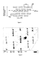
- a tungsten carbide rod was machined so as to produce a twist drill blank having a diameter of 12mm.
- the blank was provided with an ordered pattern (array) of pits in the surface of the blank corresponding to the drill body, by laser etching.
- the area to which the pattern was applied is shown in Figure 2 .
- the pattern applied to the blank is shown in Figure 3 .
- the pattern comprises "slot" shaped elongate pits arranged with their longer axis parallel to the main longitudinal axis of the drill (perpendicular to the direction of drill rotation).
- the pit density was programmed to be about 24 pits/mm 2 .
- SEM analysis indicated that burr or flash was present around the periphery of the pits.
- the blanks were therefore surface cleaned using an outer diameter grind to remove the flash.
- the resultant pits in the tool blank surface are shown in Figure 4 , which illustrates that substantially no flash remains.
- the tool blank was then machined so as to produce a drill geometry corresponding to Dormer Tools' CDX R553 commercial product.
- the cylindrical land is the only part of the twist drill that retains the pattern of pits. The rest of the surface of the tool blank is removed during the machining steps.
- the twist drill was then coated with TiAlN using a standard deposition technique.
- the depth of TiAlN coating on the tool substrate was about 1 ⁇ m.
- the coating was applied to all of the twist drill, including the cylindrical land.
- the coating extends over the pits so that, in cross-section, the tool comprises pits in the tool substrate with a layer of TiAlN following the contour of the pit (e.g. as illustrated in Figure 1 ).
- Other coatings can be used instead of TiAlN.
- the coated pits are shown in Figure 5 .
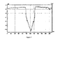
- a white light analysis width profile of a pit after coating is shown in Figure 6 .
- Example 1 The same procedure as Example 1 was followed except that the laser dwelling time was slightly longer during the laser texturing step.
- the average pit width was measured as 50 ⁇ m, the average pit length 220 ⁇ m and the average pit depth 11 ⁇ m.
- a twist drill without pits was made in the same way as Example 1 except laser texturing was not applied.
- Examples 1 and 2 and Comparative Example 1 were tested using two workpiece materials: AMG 1.5 (steel alloy) and AMG 4.3 (Titanium alloy).
- AMG 4.3 is particularly demanding because drilling of Ti workpieces is known to generate high temperatures and can even cause combustion of the Ti.
- Test 1 The following conditions and settings were used in Test 1:
- the holes were measured using a Renishaw probe (MP700 OMP70) at depths of 10mm and 30mm.
- twist drills comprising an array of pits on the cylindrical land experience acceptable levels of thrust and torque.
- Example 1 and Example 2 produced "tighter” holes than Comparative Example 1. Indeed, both examples achieved a mean hole tolerance of H7, whereas Comparative Example 1 achieved only H9 (ISO 286 "Limits and fits").
- the holes were measured using the Renishaw probe at depths of 5mm and 10mm.
- Example 1 and Example 2 produced "tighter" holes than Comparative Example 1 when used in the Ti workpiece. Furthermore, particularly at a depth of 5mm, the spread of hole size is smaller for Examples 1 and 2 as compared to Comparative Example 1.
- the consistent hole sizes achieved by the laser textured tools indicate that the laser textured tools are reducing the frictional properties of the tool.
- the excellent hole size spread at 5mm suggests that the work piece material begins to cool and restore its original shape, thus minimising the possibility of "snatching".
- the reduction in the heat generation can reduce the extent of expansion of the workpiece material thus reducing the "closing in” of the hole on the tool, which effect can cause "grabbing" of "snatching" of the tool.
- test results demonstrate that excellent hole quality can be achieved, particularly in the case of a Ti workpiece.
- laser textured tools may be particularly suitable for use with minimum quantity lubrication (MQL) because they optimise the use of the comparatively small amounts of lubricant which are applied to the tool and workpiece in MQL. This permits a reduction in the environmental impact as a result of reduced waste lubricant and a reduction in the cost for the disposal or reclamation of lubricant.
- MQL minimum quantity lubrication
Landscapes
- Engineering & Computer Science (AREA)
- Mechanical Engineering (AREA)
- Chemical & Material Sciences (AREA)
- Chemical Kinetics & Catalysis (AREA)
- Materials Engineering (AREA)
- Metallurgy (AREA)
- Organic Chemistry (AREA)
- Drilling Tools (AREA)
- Laser Beam Processing (AREA)
- Turning (AREA)
- Cutting Tools, Boring Holders, And Turrets (AREA)
Applications Claiming Priority (2)
| Application Number | Priority Date | Filing Date | Title |
|---|---|---|---|
| GB1014966.4A GB2483475B (en) | 2010-09-08 | 2010-09-08 | Bore cutting tool and method of making the same |
| PCT/GB2011/001304 WO2012032286A1 (en) | 2010-09-08 | 2011-09-05 | Bore cutting tool and method of making the same |
Publications (2)
| Publication Number | Publication Date |
|---|---|
| EP2613903A1 EP2613903A1 (en) | 2013-07-17 |
| EP2613903B1 true EP2613903B1 (en) | 2015-08-05 |
Family
ID=43037536
Family Applications (1)
| Application Number | Title | Priority Date | Filing Date |
|---|---|---|---|
| EP11757397.2A Active EP2613903B1 (en) | 2010-09-08 | 2011-09-05 | Bore cutting tool and method of making the same |
Country Status (7)
| Country | Link |
|---|---|
| US (1) | US20130302102A1 (enExample) |
| EP (1) | EP2613903B1 (enExample) |
| JP (2) | JP6173211B2 (enExample) |
| KR (2) | KR101985128B1 (enExample) |
| CN (1) | CN103237621B (enExample) |
| GB (1) | GB2483475B (enExample) |
| WO (1) | WO2012032286A1 (enExample) |
Families Citing this family (16)
| Publication number | Priority date | Publication date | Assignee | Title |
|---|---|---|---|---|
| US9656335B2 (en) | 2013-03-08 | 2017-05-23 | United Technologies Corporation | Broach tool rake face with a tailored surface topography |
| US11376675B2 (en) | 2014-04-23 | 2022-07-05 | Korloy Inc. | Cutting tool having partially-removed film formed thereon |
| KR101537718B1 (ko) * | 2014-04-23 | 2015-07-20 | 한국야금 주식회사 | 부분적으로 제거된 피막이 형성된 절삭공구 |
| CN107073597B (zh) * | 2014-10-24 | 2019-11-01 | 京瓷株式会社 | 钻头及使用该钻头的切削加工物的制造方法 |
| EP3115137A1 (en) * | 2015-07-07 | 2017-01-11 | ThyssenKrupp Metalúrgica Campo Limpo Ltda. | A machining tool |
| CN104999182B (zh) * | 2015-07-09 | 2017-04-26 | 江苏科技大学 | 高速钢切削刀具表面微造型的加工装置及其加工方法 |
| JP6604105B2 (ja) * | 2015-09-15 | 2019-11-13 | 日本製鉄株式会社 | 超硬工具及びその製造方法 |
| DE102016113348B4 (de) * | 2015-11-25 | 2025-06-18 | Gühring KG | Spanabhebendes Werkzeug mit Freiflächenstruktur zur KSS-Lenkung |
| DE102015223484B4 (de) * | 2015-11-26 | 2022-06-15 | Kennametal Inc. | Schneidwerkzeug und Verfahren zu dessen Herstellung |
| IL246227B (en) * | 2016-06-15 | 2021-07-29 | Hanita Metal Works Ltd | Fluted cutting tool configuration and method therefor |
| DE102016113571B4 (de) * | 2016-07-22 | 2025-10-16 | Gühring KG | Gewindebohrer und Verfahren |
| EP3323540A1 (en) * | 2016-11-17 | 2018-05-23 | Sandvik Intellectual Property AB | A drill device |
| GB2562730B (en) * | 2017-05-22 | 2020-07-01 | Gkn Aerospace Sweden Ab | Cooled drill |
| WO2020184667A1 (ja) | 2019-03-14 | 2020-09-17 | 京セラ株式会社 | インサートおよび切削工具 |
| EP4182118A1 (de) | 2020-08-07 | 2023-05-24 | Zecha Hartmetall-Werkzeugfabrikation GmbH | Honwerkzeug und verfahren zu dessen herstellung |
| CN116197466A (zh) * | 2023-03-07 | 2023-06-02 | 江苏徐工工程机械研究院有限公司 | 剐齿刀具及其制备方法 |
Family Cites Families (37)
| Publication number | Priority date | Publication date | Assignee | Title |
|---|---|---|---|---|
| US4629373A (en) * | 1983-06-22 | 1986-12-16 | Megadiamond Industries, Inc. | Polycrystalline diamond body with enhanced surface irregularities |
| US4784023A (en) * | 1985-12-05 | 1988-11-15 | Diamant Boart-Stratabit (Usa) Inc. | Cutting element having composite formed of cemented carbide substrate and diamond layer and method of making same |
| US4705123A (en) * | 1986-07-29 | 1987-11-10 | Strata Bit Corporation | Cutting element for a rotary drill bit and method for making same |
| EP0312281B1 (en) * | 1987-10-12 | 1993-08-25 | De Beers Industrial Diamond Division (Proprietary) Limited | Abrasive products |
| JPH0544012A (ja) * | 1991-08-08 | 1993-02-23 | Mitsubishi Heavy Ind Ltd | コーテイング部材 |
| JP3448884B2 (ja) * | 1992-12-15 | 2003-09-22 | 日本精工株式会社 | 人工ダイヤモンド被覆材 |
| US5379854A (en) * | 1993-08-17 | 1995-01-10 | Dennis Tool Company | Cutting element for drill bits |
| JPH07133704A (ja) * | 1993-11-08 | 1995-05-23 | Nissan Motor Co Ltd | カムシャフトおよびその製造方法 |
| US5585176A (en) * | 1993-11-30 | 1996-12-17 | Kennametal Inc. | Diamond coated tools and wear parts |
| US5558789A (en) * | 1994-03-02 | 1996-09-24 | University Of Florida | Method of applying a laser beam creating micro-scale surface structures prior to deposition of film for increased adhesion |
| WO1996034131A1 (fr) * | 1995-04-24 | 1996-10-31 | Toyo Kohan Co., Ltd. | Articles possedant un revetement en diamant forme par synthese en phase vapeur |
| US5722803A (en) * | 1995-07-14 | 1998-03-03 | Kennametal Inc. | Cutting tool and method of making the cutting tool |
| US5776355A (en) * | 1996-01-11 | 1998-07-07 | Saint-Gobain/Norton Industrial Ceramics Corp | Method of preparing cutting tool substrate materials for deposition of a more adherent diamond coating and products resulting therefrom |
| DE19648971A1 (de) * | 1996-11-26 | 1998-05-28 | Drebo Werkzeugfab Gmbh | Bohrer sowie Verfahren zu seiner Herstellung |
| DE19724319C1 (de) * | 1997-06-10 | 1998-10-08 | Fette Wilhelm Gmbh | Verfahren zur Beeinflussung des Spanflußverhaltens von Werkzeugflächen |
| FR2801234A1 (fr) * | 1999-06-22 | 2001-05-25 | Gaillard Jacques | Outils de coupe avec revetement diamant cvd pour l'usinage sur machines outils (cvd=chimique vapeur deposition) |
| DK1292414T3 (da) * | 2000-06-13 | 2006-01-30 | Element Six Pty Ltd | Sammensatte diamantmasser |
| JP3590579B2 (ja) * | 2000-12-11 | 2004-11-17 | オーエスジー株式会社 | ダイヤモンド被覆部材およびその製造方法 |
| DE10243403A1 (de) * | 2002-09-18 | 2004-04-01 | Hawera Probst Gmbh | Verfahren zur Herstellung eines Werkzeugs, insbesondere eines Bohrers oder Fräsers |
| JP2003251509A (ja) * | 2002-02-28 | 2003-09-09 | Univ Tohoku | 精密加工用治具、加工装置及び精密加工方法 |
| DE10208633A1 (de) * | 2002-02-28 | 2003-09-11 | Hawera Probst Gmbh | Werkzeug, insbesondere Bohrer oder Fräser, und Verfahren zu dessen Herstellung |
| JP2003300110A (ja) * | 2002-04-03 | 2003-10-21 | Osg Corp | ドリルおよびその製造方法 |
| US6852414B1 (en) * | 2002-06-25 | 2005-02-08 | Diamond Innovations, Inc. | Self sharpening polycrystalline diamond compact with high impact resistance |
| JP2005001088A (ja) * | 2003-06-13 | 2005-01-06 | Osg Corp | 硬質被膜被覆部材、およびその製造方法 |
| GB0320148D0 (en) * | 2003-08-28 | 2003-10-01 | Dormer Tools Sheffield Ltd | Partially coated drill tool |
| US20050210755A1 (en) * | 2003-09-05 | 2005-09-29 | Cho Hyun S | Doubled-sided and multi-layered PCBN and PCD abrasive articles |
| GB0323948D0 (en) * | 2003-10-13 | 2003-11-12 | Imp College Innovations Ltd | Wear-resisting surface structure |
| US9016221B2 (en) * | 2004-02-17 | 2015-04-28 | University Of Florida Research Foundation, Inc. | Surface topographies for non-toxic bioadhesion control |
| EP1725357B1 (de) * | 2004-03-17 | 2010-09-08 | Kennametal Inc. | Spiralbohrer |
| JP2005319544A (ja) * | 2004-05-10 | 2005-11-17 | Sumitomo Electric Hardmetal Corp | 穴加工用工具とその工具の外周研削方法 |
| DE102005047510A1 (de) * | 2005-10-04 | 2007-04-05 | Gühring Ohg | Spanabtragendes Werkzeug |
| US7651758B2 (en) * | 2005-10-18 | 2010-01-26 | Endres Machining Innovations Llc | System for improving the wearability of a surface and related method |
| KR20140002809A (ko) * | 2005-12-12 | 2014-01-08 | 엘리먼트 씩스 (프로덕션) (피티와이) 리미티드 | 절삭 방법 |
| JP5228303B2 (ja) * | 2006-01-24 | 2013-07-03 | 日産自動車株式会社 | 低摩擦摺動部材、その製造装置並びに製造方法 |
| JP5297381B2 (ja) * | 2007-09-14 | 2013-09-25 | 住友電気工業株式会社 | 切削工具用チップ及び被覆切削工具 |
| CN101125371A (zh) * | 2007-09-25 | 2008-02-20 | 山东大学 | 一种微池自润滑刀具及其制备方法 |
| US9144845B1 (en) * | 2012-03-01 | 2015-09-29 | The Boeing Company | Cutting tools with textured surfaces |
-
2010
- 2010-09-08 GB GB1014966.4A patent/GB2483475B/en active Active
-
2011
- 2011-09-05 WO PCT/GB2011/001304 patent/WO2012032286A1/en not_active Ceased
- 2011-09-05 KR KR1020177027295A patent/KR101985128B1/ko active Active
- 2011-09-05 US US13/821,354 patent/US20130302102A1/en not_active Abandoned
- 2011-09-05 JP JP2013527672A patent/JP6173211B2/ja active Active
- 2011-09-05 CN CN201180043470.0A patent/CN103237621B/zh active Active
- 2011-09-05 EP EP11757397.2A patent/EP2613903B1/en active Active
- 2011-09-05 KR KR1020137008890A patent/KR20130137169A/ko not_active Ceased
-
2015
- 2015-12-25 JP JP2015254197A patent/JP2016052716A/ja active Pending
Also Published As
| Publication number | Publication date |
|---|---|
| KR101985128B1 (ko) | 2019-05-31 |
| CN103237621B (zh) | 2016-05-18 |
| JP6173211B2 (ja) | 2017-08-02 |
| KR20170116189A (ko) | 2017-10-18 |
| JP2016052716A (ja) | 2016-04-14 |
| EP2613903A1 (en) | 2013-07-17 |
| GB201014966D0 (en) | 2010-10-20 |
| US20130302102A1 (en) | 2013-11-14 |
| WO2012032286A1 (en) | 2012-03-15 |
| CN103237621A (zh) | 2013-08-07 |
| JP2013537114A (ja) | 2013-09-30 |
| GB2483475B (en) | 2015-08-05 |
| KR20130137169A (ko) | 2013-12-16 |
| GB2483475A (en) | 2012-03-14 |
Similar Documents
| Publication | Publication Date | Title |
|---|---|---|
| EP2613903B1 (en) | Bore cutting tool and method of making the same | |
| Swain et al. | An experimental investigation on the machining characteristics of Nimonic 75 using uncoated and TiAlN coated tungsten carbide micro-end mills | |
| Grzesik et al. | Surface integrity of machined surfaces | |
| Peng et al. | Integration of finishing and surface treatment of Inconel 718 alloy using high-speed ultrasonic vibration cutting | |
| Jindal | Analysis of tool wear rate in drilling operation using scanning electron microscope (SEM) | |
| Siller et al. | Study of face milling of hardened AISI D3 steel with a special design of carbide tools | |
| Okafor et al. | Effects of milling methods and cooling strategies on tool wear, chip morphology and surface roughness in high speed end-milling of Inconel-718 | |
| EP1660694B1 (en) | Coated bore cutting tools | |
| de Oliveira et al. | Tool life and tool wear in the semi-finish milling of inclined surfaces | |
| Afzal et al. | Exploring novel PVD coated wiper inserts’ chip breaker designs and feed rates on tool wear and in-depth hole integrity of Ti-6Al-4V alloy when drilling in a dry environment | |
| Kannan et al. | Experimental investigation of surface integrity during abrasive edge profiling of nickel-based alloy | |
| Vogel et al. | Problems encountered with the introduction of ion plating to large‐scale coating of tools | |
| US11524345B2 (en) | Bore cutting tool and method of making the same | |
| Heinemann et al. | Investigating the feasibility of DLC-coated twist drills in deep-hole drilling | |
| JP3633837B2 (ja) | 被覆工具 | |
| Nicolodi et al. | Effect of wear progression in an'S'-type mixed ceramic tool on machining forces and surface roughness in the turning of hardened AISI 4140 steel | |
| CN111665159B (zh) | 一种延长金属切削涂层刀具寿命的方法 | |
| Roy et al. | Cutting performance analysis of surface textured tools in dry turning: optimisation of process parameters | |
| JP2022143008A (ja) | 切削工具および切削工具の製造方法 | |
| Chen et al. | The cutting performance of a TiN-coated drill with curved primary cutting edges | |
| YALÇINKAYA et al. | Investigation of the effects of coated and uncoated drills on hole quality in drilling of steel used in molding | |
| Martins et al. | Influence of hydraulic and interference-fit tool holders on tool wear and hole quality in the drilling of Al-Si cylinder heads | |
| Bhople et al. | Performance analysis of uncoated, TiN coated and cryotreated micro tungsten carbide tools while micromilling of Ti-6Al-4V | |
| JP2005059120A (ja) | 切削工具 | |
| binti Hassan | EVALUATING TOOL WEAR AND HOLE QUALITY IN DRY DRILLING: A STUDY ON CYLINDRICITY DEVIATION AND TOOL LIFE BEYOND FAILURE |
Legal Events
| Date | Code | Title | Description |
|---|---|---|---|
| PUAI | Public reference made under article 153(3) epc to a published international application that has entered the european phase |
Free format text: ORIGINAL CODE: 0009012 |
|
| 17P | Request for examination filed |
Effective date: 20130408 |
|
| AK | Designated contracting states |
Kind code of ref document: A1 Designated state(s): AL AT BE BG CH CY CZ DE DK EE ES FI FR GB GR HR HU IE IS IT LI LT LU LV MC MK MT NL NO PL PT RO RS SE SI SK SM TR |
|
| DAX | Request for extension of the european patent (deleted) | ||
| 17Q | First examination report despatched |
Effective date: 20140414 |
|
| RIC1 | Information provided on ipc code assigned before grant |
Ipc: B23B 51/02 20060101AFI20150306BHEP Ipc: B23B 51/06 20060101ALI20150306BHEP Ipc: C23C 30/00 20060101ALI20150306BHEP |
|
| GRAP | Despatch of communication of intention to grant a patent |
Free format text: ORIGINAL CODE: EPIDOSNIGR1 |
|
| INTG | Intention to grant announced |
Effective date: 20150417 |
|
| GRAS | Grant fee paid |
Free format text: ORIGINAL CODE: EPIDOSNIGR3 |
|
| GRAA | (expected) grant |
Free format text: ORIGINAL CODE: 0009210 |
|
| AK | Designated contracting states |
Kind code of ref document: B1 Designated state(s): AL AT BE BG CH CY CZ DE DK EE ES FI FR GB GR HR HU IE IS IT LI LT LU LV MC MK MT NL NO PL PT RO RS SE SI SK SM TR |
|
| REG | Reference to a national code |
Ref country code: GB Ref legal event code: FG4D |
|
| REG | Reference to a national code |
Ref country code: CH Ref legal event code: EP |
|
| REG | Reference to a national code |
Ref country code: AT Ref legal event code: REF Ref document number: 740402 Country of ref document: AT Kind code of ref document: T Effective date: 20150815 |
|
| REG | Reference to a national code |
Ref country code: IE Ref legal event code: FG4D |
|
| REG | Reference to a national code |
Ref country code: FR Ref legal event code: PLFP Year of fee payment: 5 |
|
| REG | Reference to a national code |
Ref country code: DE Ref legal event code: R096 Ref document number: 602011018488 Country of ref document: DE |
|
| REG | Reference to a national code |
Ref country code: AT Ref legal event code: MK05 Ref document number: 740402 Country of ref document: AT Kind code of ref document: T Effective date: 20150805 |
|
| REG | Reference to a national code |
Ref country code: LT Ref legal event code: MG4D |
|
| REG | Reference to a national code |
Ref country code: NL Ref legal event code: MP Effective date: 20150805 |
|
| PG25 | Lapsed in a contracting state [announced via postgrant information from national office to epo] |
Ref country code: FI Free format text: LAPSE BECAUSE OF FAILURE TO SUBMIT A TRANSLATION OF THE DESCRIPTION OR TO PAY THE FEE WITHIN THE PRESCRIBED TIME-LIMIT Effective date: 20150805 Ref country code: NO Free format text: LAPSE BECAUSE OF FAILURE TO SUBMIT A TRANSLATION OF THE DESCRIPTION OR TO PAY THE FEE WITHIN THE PRESCRIBED TIME-LIMIT Effective date: 20151105 Ref country code: LV Free format text: LAPSE BECAUSE OF FAILURE TO SUBMIT A TRANSLATION OF THE DESCRIPTION OR TO PAY THE FEE WITHIN THE PRESCRIBED TIME-LIMIT Effective date: 20150805 Ref country code: GR Free format text: LAPSE BECAUSE OF FAILURE TO SUBMIT A TRANSLATION OF THE DESCRIPTION OR TO PAY THE FEE WITHIN THE PRESCRIBED TIME-LIMIT Effective date: 20151106 Ref country code: LT Free format text: LAPSE BECAUSE OF FAILURE TO SUBMIT A TRANSLATION OF THE DESCRIPTION OR TO PAY THE FEE WITHIN THE PRESCRIBED TIME-LIMIT Effective date: 20150805 |
|
| PG25 | Lapsed in a contracting state [announced via postgrant information from national office to epo] |
Ref country code: IS Free format text: LAPSE BECAUSE OF FAILURE TO SUBMIT A TRANSLATION OF THE DESCRIPTION OR TO PAY THE FEE WITHIN THE PRESCRIBED TIME-LIMIT Effective date: 20151205 Ref country code: AT Free format text: LAPSE BECAUSE OF FAILURE TO SUBMIT A TRANSLATION OF THE DESCRIPTION OR TO PAY THE FEE WITHIN THE PRESCRIBED TIME-LIMIT Effective date: 20150805 Ref country code: HR Free format text: LAPSE BECAUSE OF FAILURE TO SUBMIT A TRANSLATION OF THE DESCRIPTION OR TO PAY THE FEE WITHIN THE PRESCRIBED TIME-LIMIT Effective date: 20150805 Ref country code: RS Free format text: LAPSE BECAUSE OF FAILURE TO SUBMIT A TRANSLATION OF THE DESCRIPTION OR TO PAY THE FEE WITHIN THE PRESCRIBED TIME-LIMIT Effective date: 20150805 Ref country code: ES Free format text: LAPSE BECAUSE OF FAILURE TO SUBMIT A TRANSLATION OF THE DESCRIPTION OR TO PAY THE FEE WITHIN THE PRESCRIBED TIME-LIMIT Effective date: 20150805 Ref country code: SE Free format text: LAPSE BECAUSE OF FAILURE TO SUBMIT A TRANSLATION OF THE DESCRIPTION OR TO PAY THE FEE WITHIN THE PRESCRIBED TIME-LIMIT Effective date: 20150805 Ref country code: PT Free format text: LAPSE BECAUSE OF FAILURE TO SUBMIT A TRANSLATION OF THE DESCRIPTION OR TO PAY THE FEE WITHIN THE PRESCRIBED TIME-LIMIT Effective date: 20151207 Ref country code: PL Free format text: LAPSE BECAUSE OF FAILURE TO SUBMIT A TRANSLATION OF THE DESCRIPTION OR TO PAY THE FEE WITHIN THE PRESCRIBED TIME-LIMIT Effective date: 20150805 |
|
| PG25 | Lapsed in a contracting state [announced via postgrant information from national office to epo] |
Ref country code: NL Free format text: LAPSE BECAUSE OF FAILURE TO SUBMIT A TRANSLATION OF THE DESCRIPTION OR TO PAY THE FEE WITHIN THE PRESCRIBED TIME-LIMIT Effective date: 20150805 |
|
| PG25 | Lapsed in a contracting state [announced via postgrant information from national office to epo] |
Ref country code: SK Free format text: LAPSE BECAUSE OF FAILURE TO SUBMIT A TRANSLATION OF THE DESCRIPTION OR TO PAY THE FEE WITHIN THE PRESCRIBED TIME-LIMIT Effective date: 20150805 Ref country code: CZ Free format text: LAPSE BECAUSE OF FAILURE TO SUBMIT A TRANSLATION OF THE DESCRIPTION OR TO PAY THE FEE WITHIN THE PRESCRIBED TIME-LIMIT Effective date: 20150805 Ref country code: DK Free format text: LAPSE BECAUSE OF FAILURE TO SUBMIT A TRANSLATION OF THE DESCRIPTION OR TO PAY THE FEE WITHIN THE PRESCRIBED TIME-LIMIT Effective date: 20150805 Ref country code: EE Free format text: LAPSE BECAUSE OF FAILURE TO SUBMIT A TRANSLATION OF THE DESCRIPTION OR TO PAY THE FEE WITHIN THE PRESCRIBED TIME-LIMIT Effective date: 20150805 |
|
| REG | Reference to a national code |
Ref country code: CH Ref legal event code: PL |
|
| REG | Reference to a national code |
Ref country code: DE Ref legal event code: R097 Ref document number: 602011018488 Country of ref document: DE |
|
| PG25 | Lapsed in a contracting state [announced via postgrant information from national office to epo] |
Ref country code: RO Free format text: LAPSE BECAUSE OF FAILURE TO SUBMIT A TRANSLATION OF THE DESCRIPTION OR TO PAY THE FEE WITHIN THE PRESCRIBED TIME-LIMIT Effective date: 20150805 Ref country code: MC Free format text: LAPSE BECAUSE OF FAILURE TO SUBMIT A TRANSLATION OF THE DESCRIPTION OR TO PAY THE FEE WITHIN THE PRESCRIBED TIME-LIMIT Effective date: 20150805 |
|
| PLBE | No opposition filed within time limit |
Free format text: ORIGINAL CODE: 0009261 |
|
| STAA | Information on the status of an ep patent application or granted ep patent |
Free format text: STATUS: NO OPPOSITION FILED WITHIN TIME LIMIT |
|
| REG | Reference to a national code |
Ref country code: IE Ref legal event code: MM4A |
|
| 26N | No opposition filed |
Effective date: 20160509 |
|
| PG25 | Lapsed in a contracting state [announced via postgrant information from national office to epo] |
Ref country code: IE Free format text: LAPSE BECAUSE OF NON-PAYMENT OF DUE FEES Effective date: 20150905 Ref country code: LI Free format text: LAPSE BECAUSE OF NON-PAYMENT OF DUE FEES Effective date: 20150930 Ref country code: CH Free format text: LAPSE BECAUSE OF NON-PAYMENT OF DUE FEES Effective date: 20150930 |
|
| REG | Reference to a national code |
Ref country code: FR Ref legal event code: PLFP Year of fee payment: 6 |
|
| PG25 | Lapsed in a contracting state [announced via postgrant information from national office to epo] |
Ref country code: SI Free format text: LAPSE BECAUSE OF FAILURE TO SUBMIT A TRANSLATION OF THE DESCRIPTION OR TO PAY THE FEE WITHIN THE PRESCRIBED TIME-LIMIT Effective date: 20150805 |
|
| PG25 | Lapsed in a contracting state [announced via postgrant information from national office to epo] |
Ref country code: BE Free format text: LAPSE BECAUSE OF FAILURE TO SUBMIT A TRANSLATION OF THE DESCRIPTION OR TO PAY THE FEE WITHIN THE PRESCRIBED TIME-LIMIT Effective date: 20150805 |
|
| PG25 | Lapsed in a contracting state [announced via postgrant information from national office to epo] |
Ref country code: MT Free format text: LAPSE BECAUSE OF FAILURE TO SUBMIT A TRANSLATION OF THE DESCRIPTION OR TO PAY THE FEE WITHIN THE PRESCRIBED TIME-LIMIT Effective date: 20150805 |
|
| PG25 | Lapsed in a contracting state [announced via postgrant information from national office to epo] |
Ref country code: BG Free format text: LAPSE BECAUSE OF FAILURE TO SUBMIT A TRANSLATION OF THE DESCRIPTION OR TO PAY THE FEE WITHIN THE PRESCRIBED TIME-LIMIT Effective date: 20150805 Ref country code: SM Free format text: LAPSE BECAUSE OF FAILURE TO SUBMIT A TRANSLATION OF THE DESCRIPTION OR TO PAY THE FEE WITHIN THE PRESCRIBED TIME-LIMIT Effective date: 20150805 Ref country code: HU Free format text: LAPSE BECAUSE OF FAILURE TO SUBMIT A TRANSLATION OF THE DESCRIPTION OR TO PAY THE FEE WITHIN THE PRESCRIBED TIME-LIMIT; INVALID AB INITIO Effective date: 20110905 |
|
| PG25 | Lapsed in a contracting state [announced via postgrant information from national office to epo] |
Ref country code: CY Free format text: LAPSE BECAUSE OF FAILURE TO SUBMIT A TRANSLATION OF THE DESCRIPTION OR TO PAY THE FEE WITHIN THE PRESCRIBED TIME-LIMIT Effective date: 20150805 |
|
| REG | Reference to a national code |
Ref country code: FR Ref legal event code: PLFP Year of fee payment: 7 |
|
| PG25 | Lapsed in a contracting state [announced via postgrant information from national office to epo] |
Ref country code: LU Free format text: LAPSE BECAUSE OF NON-PAYMENT OF DUE FEES Effective date: 20150905 |
|
| PG25 | Lapsed in a contracting state [announced via postgrant information from national office to epo] |
Ref country code: MK Free format text: LAPSE BECAUSE OF FAILURE TO SUBMIT A TRANSLATION OF THE DESCRIPTION OR TO PAY THE FEE WITHIN THE PRESCRIBED TIME-LIMIT Effective date: 20150805 Ref country code: TR Free format text: LAPSE BECAUSE OF FAILURE TO SUBMIT A TRANSLATION OF THE DESCRIPTION OR TO PAY THE FEE WITHIN THE PRESCRIBED TIME-LIMIT Effective date: 20150805 |
|
| REG | Reference to a national code |
Ref country code: FR Ref legal event code: PLFP Year of fee payment: 8 |
|
| PG25 | Lapsed in a contracting state [announced via postgrant information from national office to epo] |
Ref country code: AL Free format text: LAPSE BECAUSE OF FAILURE TO SUBMIT A TRANSLATION OF THE DESCRIPTION OR TO PAY THE FEE WITHIN THE PRESCRIBED TIME-LIMIT Effective date: 20150805 |
|
| P01 | Opt-out of the competence of the unified patent court (upc) registered |
Effective date: 20230603 |
|
| PGFP | Annual fee paid to national office [announced via postgrant information from national office to epo] |
Ref country code: DE Payment date: 20240730 Year of fee payment: 14 |
|
| PGFP | Annual fee paid to national office [announced via postgrant information from national office to epo] |
Ref country code: GB Payment date: 20240801 Year of fee payment: 14 |
|
| PGFP | Annual fee paid to national office [announced via postgrant information from national office to epo] |
Ref country code: FR Payment date: 20240821 Year of fee payment: 14 |
|
| PGFP | Annual fee paid to national office [announced via postgrant information from national office to epo] |
Ref country code: IT Payment date: 20240812 Year of fee payment: 14 |