EP2608991B1 - Dispositifs pour systèmes de protection de personnes d'un véhicule - Google Patents
Dispositifs pour systèmes de protection de personnes d'un véhicule Download PDFInfo
- Publication number
- EP2608991B1 EP2608991B1 EP11743218.7A EP11743218A EP2608991B1 EP 2608991 B1 EP2608991 B1 EP 2608991B1 EP 11743218 A EP11743218 A EP 11743218A EP 2608991 B1 EP2608991 B1 EP 2608991B1
- Authority
- EP
- European Patent Office
- Prior art keywords
- gas
- conducting element
- gas generator
- tab
- generator
- Prior art date
- Legal status (The legal status is an assumption and is not a legal conclusion. Google has not performed a legal analysis and makes no representation as to the accuracy of the status listed.)
- Active
Links
- 238000005304 joining Methods 0.000 claims description 60
- 239000000463 material Substances 0.000 claims description 33
- 230000002093 peripheral effect Effects 0.000 claims description 22
- 230000033001 locomotion Effects 0.000 claims description 20
- 230000002787 reinforcement Effects 0.000 claims description 10
- 238000005452 bending Methods 0.000 claims description 2
- 230000004913 activation Effects 0.000 claims 3
- 239000007789 gas Substances 0.000 description 324
- 206010053648 Vascular occlusion Diseases 0.000 description 11
- 239000000725 suspension Substances 0.000 description 11
- 238000003780 insertion Methods 0.000 description 9
- 230000037431 insertion Effects 0.000 description 9
- 238000007373 indentation Methods 0.000 description 5
- 239000002184 metal Substances 0.000 description 4
- 238000004080 punching Methods 0.000 description 4
- 238000003466 welding Methods 0.000 description 4
- 230000008901 benefit Effects 0.000 description 3
- 230000003321 amplification Effects 0.000 description 2
- 238000002347 injection Methods 0.000 description 2
- 239000007924 injection Substances 0.000 description 2
- 230000007246 mechanism Effects 0.000 description 2
- 238000003199 nucleic acid amplification method Methods 0.000 description 2
- 239000000243 solution Substances 0.000 description 2
- 230000005540 biological transmission Effects 0.000 description 1
- 230000015572 biosynthetic process Effects 0.000 description 1
- 230000008859 change Effects 0.000 description 1
- 210000000038 chest Anatomy 0.000 description 1
- 150000001875 compounds Chemical class 0.000 description 1
- 238000009826 distribution Methods 0.000 description 1
- 239000004744 fabric Substances 0.000 description 1
- 238000004519 manufacturing process Methods 0.000 description 1
- 238000000034 method Methods 0.000 description 1
- 238000012986 modification Methods 0.000 description 1
- 230000004048 modification Effects 0.000 description 1
- 230000008569 process Effects 0.000 description 1
Images


Classifications
-
- B—PERFORMING OPERATIONS; TRANSPORTING
- B60—VEHICLES IN GENERAL
- B60R—VEHICLES, VEHICLE FITTINGS, OR VEHICLE PARTS, NOT OTHERWISE PROVIDED FOR
- B60R21/00—Arrangements or fittings on vehicles for protecting or preventing injuries to occupants or pedestrians in case of accidents or other traffic risks
- B60R21/02—Occupant safety arrangements or fittings, e.g. crash pads
- B60R21/16—Inflatable occupant restraints or confinements designed to inflate upon impact or impending impact, e.g. air bags
- B60R21/26—Inflatable occupant restraints or confinements designed to inflate upon impact or impending impact, e.g. air bags characterised by the inflation fluid source or means to control inflation fluid flow
- B60R21/261—Inflatable occupant restraints or confinements designed to inflate upon impact or impending impact, e.g. air bags characterised by the inflation fluid source or means to control inflation fluid flow with means other than bag structure to diffuse or guide inflation fluid
-
- B—PERFORMING OPERATIONS; TRANSPORTING
- B60—VEHICLES IN GENERAL
- B60R—VEHICLES, VEHICLE FITTINGS, OR VEHICLE PARTS, NOT OTHERWISE PROVIDED FOR
- B60R21/00—Arrangements or fittings on vehicles for protecting or preventing injuries to occupants or pedestrians in case of accidents or other traffic risks
- B60R21/02—Occupant safety arrangements or fittings, e.g. crash pads
- B60R21/16—Inflatable occupant restraints or confinements designed to inflate upon impact or impending impact, e.g. air bags
- B60R21/20—Arrangements for storing inflatable members in their non-use or deflated condition; Arrangement or mounting of air bag modules or components
- B60R21/217—Inflation fluid source retainers, e.g. reaction canisters; Connection of bags, covers, diffusers or inflation fluid sources therewith or together
- B60R21/2171—Inflation fluid source retainers, e.g. reaction canisters; Connection of bags, covers, diffusers or inflation fluid sources therewith or together specially adapted for elongated cylindrical or bottle-like inflators with a symmetry axis perpendicular to the main direction of bag deployment, e.g. extruded reaction canisters
-
- B—PERFORMING OPERATIONS; TRANSPORTING
- B60—VEHICLES IN GENERAL
- B60R—VEHICLES, VEHICLE FITTINGS, OR VEHICLE PARTS, NOT OTHERWISE PROVIDED FOR
- B60R21/00—Arrangements or fittings on vehicles for protecting or preventing injuries to occupants or pedestrians in case of accidents or other traffic risks
- B60R21/02—Occupant safety arrangements or fittings, e.g. crash pads
- B60R21/16—Inflatable occupant restraints or confinements designed to inflate upon impact or impending impact, e.g. air bags
- B60R21/26—Inflatable occupant restraints or confinements designed to inflate upon impact or impending impact, e.g. air bags characterised by the inflation fluid source or means to control inflation fluid flow
- B60R21/261—Inflatable occupant restraints or confinements designed to inflate upon impact or impending impact, e.g. air bags characterised by the inflation fluid source or means to control inflation fluid flow with means other than bag structure to diffuse or guide inflation fluid
- B60R2021/2612—Gas guiding means, e.g. ducts
-
- Y—GENERAL TAGGING OF NEW TECHNOLOGICAL DEVELOPMENTS; GENERAL TAGGING OF CROSS-SECTIONAL TECHNOLOGIES SPANNING OVER SEVERAL SECTIONS OF THE IPC; TECHNICAL SUBJECTS COVERED BY FORMER USPC CROSS-REFERENCE ART COLLECTIONS [XRACs] AND DIGESTS
- Y10—TECHNICAL SUBJECTS COVERED BY FORMER USPC
- Y10T—TECHNICAL SUBJECTS COVERED BY FORMER US CLASSIFICATION
- Y10T403/00—Joints and connections
- Y10T403/70—Interfitted members
- Y10T403/7005—Lugged member, rotary engagement
- Y10T403/7007—Bayonet joint
Definitions
- the invention relates to devices for personal protection systems of a vehicle according to the preambles of claims 1, 7 and 10.
- gas bag devices used as vehicle occupant restraint systems there is generally the requirement to divert the gas flowing out of a gas generator in the axial and / or radial direction into one or more specific directions, so that the gas can fill a gas bag uniformly and in a defined manner. Furthermore, it is generally desirable to ensure that the gas bag adjacent to the outflow openings of a gas generator is not damaged by the outflowing gases.
- the DE 298 15 940 U1 describes devices for a personal protection system of a vehicle having the features of the preambles of independent claims 1, 7 and 10.
- the present invention has for its object to provide a further device for a personal protection system of a vehicle is available, which allows attachment of a gas guide element to a bolt provided with gas generator.
- a first embodiment of the invention provides that the gas guide element is connected by means of a bayonet closure with at least one of the stud bolts of the gas generator.
- a bayonet closure is understood to be any type of closure in which a connection of the gas-conducting element to the stud or the gas generator has at least one axial plug movement and one transverse thereto, ie. comprises circumferential rotational movement. This can be followed by further relative movements until the stud has reached its end position in the bayonet lock. The axial insertion movement can, but does not have to be in guided form.
- the gas-conducting element for forming a bayonet closure forms a joining channel for a stud bolt of the gas generator.
- this joining channel is shaped in such a way that it has a first, essentially axially extending region and a second, essentially transverse region adjoining the first region. This can be followed by a third, adjoining the second region and again in turn substantially axially extending region.
- the additional third area provides additional security for the connection.
- the connection can not be released again by just turning the gas guide element. In particular a unintentional release of the connection by shaking movements is thereby reliably prevented.
- the joining channel consists exclusively of a region running essentially transversely to the longitudinal axis of the gas-conducting element, which region is formed on an axially protruding part of the gas-conducting element.
- the gas guide element has means for locking the bayonet closure.
- the means for locking the bayonet closure comprises a resiliently arranged on the gas guide or trained locking lug which locks the stud after reaching its end position in the bayonet lock. The detent protrudes into the joining channel, so that it is deflected upon insertion of the stud into the joining channel.
- the gas guide element consists of a rolled blank and the locking lug is formed on the blank.
- Two longitudinal edges of the blank overlap in a rolled condition, the degree of overlap varying upon the occurrence of a circumferentially occurring force.
- the detent is designed as a resilient tongue in the region of the joining channel.
- the means for locking the bayonet closure comprise a flap arranged on the gas guide, which projects in the unassembled state obliquely into the interior of the gas guide element and which aligns when placing a nut or the like on the stud and tightening the nut straight and while the gas guide additionally fixed to the gas generator.
- the means for locking the bayonet closure comprise a bendable lug arranged on the gas-conducting element, by means of which the bayonet closure can be secured after reaching the end position of the stud by bending over the lug.
- the invention further provides that the gas guide element is formed in the region in which it forms the joining channel, at least partially by a flap projecting axially from the peripheral wall of the gas guide element.
- the gas guide element in the region in which it forms the joining channel at least partially on a material reinforcement. This makes it possible to ensure, even with a low material thickness of the gas-conducting element, that forces occurring when gas flows from the gas generator into the gas-conducting element can be reliably controlled.
- a tab of the gas guiding element is formed by folding one another at least two tab parts or a material doubler is arranged on the tab, so that the tab has an increased material thickness in comparison with the peripheral wall of the gas guiding element.
- the gas-conducting element is connected to the gas generator in such a way that the gas-conducting element has at least one recess into which a stud bolt of the gas generator is inserted in the axial direction onto the gas generator when the gas-conducting element is slid on.
- the gas-conducting element furthermore has at least one securing element which is provided and designed to be suspended in a further structure and thereby additionally secure the gas-conducting element in the axial direction on the gas generator.
- the hanging can be done for example in a module rack or in a gas bag of a gas bag module.
- the fuse element is used when gas flows from the gas generator in the Gas guide and thereby strong axial forces to secure the gas guide additionally axially on the gas generator.
- an attachment of the securing element in a further structure is to be understood as meaning that the securing element is not firmly connected to the further structure. Separate attachment measures are therefore not required.
- the securing element is designed as a tab which extends through an eyelet or opening of the structure and is suspended thereby.
- Said recess is for example elongated and axially aligned. Their width is at least as large as the diameter of the stud, so that it is arranged without clamping in the recess.
- the recess is formed on an axially projecting from the peripheral wall of the gas guide member. It is provided, for example, between two latching arms, which protrude from the end face of the gas guide element.
- Next locking means are provided in an alternative embodiment, which lock a introduced into the recess stud bolts therein. Upon insertion of the stud into the recess of this is thus additionally locked in the recess, so that at least with only slight axial forces and axial fixation of the gas guide element and gas generator takes place.
- the latching means are provided for example by formed on latching arms, inwardly projecting projections which narrow the recess in this area.
- the securing element according to the invention is formed by a Ein vonsche, wherein the end of the Ein vonsche points in a direction which is directed away from the gas generator.
- a suspension is made possible in such a way that a safeguard against axial forces is given, which can occur when gas flows into the gas-conducting element and push away the gas-conducting element from the gas generator.
- the securing element can be arranged in various ways on the gas guide, both the front side and at the periphery. It may be formed integral part of the gas guide or by a separate, fixed to the gas guide member.
- the recess of the gas guide element is formed in a part which, starting from its connection to the peripheral wall of Gas guide element extends in a first direction. Furthermore, the securing element extends from its connection with the peripheral wall of the gas guiding element in a second direction, wherein the first direction and the second direction are opposite. The securing element and the fixing element thus extend in the opposite direction.
- the gas-conducting element is connected to the gas generator in such a way that the gas-conducting element has a substantially transverse joining channel, into which at least one of the stud bolts of the gas generator can be introduced by a rotational movement in the circumferential direction, the joining channel at least Partially formed on a front side axially projecting part of the gas guide.
- the beginning of the joining channel is located at a lateral edge of the projecting part.
- the fact that the joining channel runs essentially transversely is to be understood to mean that it runs more in the transverse direction than in the axial direction, which of course also implies that it runs approximately exactly in the transverse direction.
- the joining channel can be formed straight or curved.
- the protruding part has a bendable or flexible tab, by means of which the joining channel can be closed after insertion of the stud into the joining channel.
- the tab is first bent up to release the joining channel, and it is bent back after insertion of the stud into the joining channel to re-close the joining channel and to secure the stud in the joining channel against loosening.
- the projecting part is formed by folding a section cut out in the flatly spread material blank of the gas guide element, which is connected to the material blank only via a folding axis running in the axial direction, onto a part region of the material blank that is substantially symmetrical therefor.
- transversely extending regions of the joining channel are formed in both sub-regions, which come to lie one above the other on the other sub-region after flaps of one sub-region.
- the substantially transverse joining channel widens towards its end, for example by forming an approximately circular region. This can be associated with the advantage of a certain clearance between the gas guiding element and the gas generator in the locked state.
- a further exemplary embodiment of the invention provides that at least one punctiform or linear constriction is formed in the circumferential wall of the gas guide element, which provides a tilt protection of the gas guide element with respect to the gas generator.
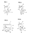
- the FIG. 1 shows a sleeve-shaped gas guide element 1.
- the gas guide 1 is intended to divert gas flowing from a gas generator and in desired way to lead into a gas bag. It can be provided that the gas-conducting element divides the gas flow provided by a gas generator into a plurality of partial flows. This is not mandatory. Likewise, it can be provided that the gas-conducting element discharges the gas flow substantially in one direction.
- the gas guide element has one or more openings for the outflow of gas from the gas guide and / or the connection of the gas guide element with a gas generator is substantially gas-tight or non-gas-tight.
- gas guide elements are described in which gas escapes in a certain way from the gas guide element, it will be apparent to those skilled in the art that in these embodiments the gas exit from the gas guide element can also be realized in another way, without departing from the basic concepts of the present invention Invention, which relate to the attachment of a sleeve-shaped gas guide element to a gas generator to deviate.
- the gas guide element 1 has a first end 11 and a second end 12.
- the first end 11 is intended to be connected to a tube gas generator.
- the second end 12 is provided to direct gas discharged from a gas generator into an airbag.
- gas-conducting element 1 is tubular, for which purpose it has a cylindrical peripheral wall 13 provided with an inner bore 14.
- a slot-shaped recess 2 is realized in the gas guide element 1, which forms a joining channel of a bayonet closure. It is designed to form a bayonet closure together with a stud of a gas generator and accordingly has a width which allows to introduce such a stud into the recess 2.
- the recess 2 has a first region 21 extending axially with respect to the longitudinal axis of the gas-conducting element 1, a region 22 extending in the transverse direction (ie in the circumferential direction) and a region 23 which extends back axially.
- the in the FIG. 1 shown shape of the slot-shaped recess 2 for the realization of the bayonet closure is to be understood only as an example.
- the length and shape of the last region 23 can also be embodied in a different way. It is also possible to dispense entirely with the region 23, in particular when the stud bolt is additionally secured in the recess 2 of the gas-conducting element by means of a latching mechanism.
- the gas guide element 1 may for example consist of plastic or metal. It can be designed as a drawn or rolled part.
- the opening shown at the second end 12 may also be formed in a different form than shown, for example, slot-like manner in the peripheral wall 13 extend. Further, embodiments may be provided in which the second end 12 is formed closed.
- the shape of the gas guide element is variable. For example, this may be formed instead of cylindrical oval or conical, especially when the areas of the gas guide, which participate in the realization of a bayonet closure, are formed on a protruding tab, as for example in the FIG. 2 is shown.
- the gas guide 1 may be formed as an elongated Gasleitrohr with a plurality of lateral gas outlet openings.
- FIGS. 2 and 3 show an alternative embodiment of a gas guide element 1, wherein the FIG. 3 represents the unrolled state of the gas-conducting element 1.
- the gas-conducting element 1 is likewise designed in the shape of a cylinder with a first end 11, a second end 12, a peripheral wall 13 and an inner bore 14.
- the first end 11 is formed by an axially projecting tab 15 of the peripheral wall 13, which is a frontally axially projecting part of the gas guide element 1.
- the tab 15 is formed integrally with the peripheral wall 13. It has two with respect to an axis 151 axisymmetric parts 15a, 15b, which are folded on each other, whereby a reinforced flap 15 is formed with double the material thickness.
- the reinforcement can take place inwards or outwards, ie the segment 15a can come to rest under the segment 15b or on the segment 15b. In both cases, an amplification of the area provided for the bayonet closure is provided, so that axial forces occurring in the triggering case can be safely absorbed even with a small material thickness of the gas-conducting element 1.
- the slot-shaped recess 2a for receiving a stud of a gas generator is designed such that the first axial portion 21a is defined by the lateral edge of the tab 15 extending transversely Region 22a substantially by a recess in the peripheral wall 13 and the turn axially extending portion 23a are realized by recesses in the two axially symmetrical flap parts 15a, 15b, so that this last region 23a, in which the stud of the gas generator is positioned in the assembled state , reinforced is formed.
- the axial plugging motion between the gas guide element 1 and studs is not carried out in guided form, since the first axial portion 21 a only a lateral stop and not limited on both sides recess.
- FIGS. 23 to 25B show a further embodiment of a gas guide element 1, which is similar to the embodiment of the FIGS. 2 and 3 is trained.
- the FIG. 23 shows the unrolled state of the gas-conducting element 1, showing a material blank 20.
- the gas guide element 1 is in turn cylindrically shaped and has a first end 11, a second end 12, a peripheral wall 13 and an inner bore 14.
- the first end 11 is formed by a protruding part 15, which according to the FIG. 23 is formed by folding a portion 15a cut out in the flat-out material blank 20 onto a partial area 15b of the material blank 20 designed to be substantially symmetrical therewith.
- the cut-out portion 15a is connected to the material blank 20 only via a folding axis 151 running in the axial direction.
- a transverse region 22b is formed both in the subregion 15a and in the subregion 15b, the regions 22b coming over the subregion 15b after flaps of the subregion 15a and forming a joining channel 2b.
- the partial regions 15a and 15b are largely axially symmetrical with respect to the folding axis 151.
- a certain deviation from a complete axial symmetry is given, on the one hand, in that a bendable tab 30 is formed in the partial area 15a at its end lying in the circumferential direction, which protrudes into the joining channel 2b and the transverse region 22b.
- a further deviation from a complete axial symmetry is that the portion 15b of the material blank 20 has a nose-like elevation 26b at the beginning of the transverse region 22b. This is optional and can serve to more securely insert a stud into the joining channel 2b.
- a reinforced protruding part 15 with a double material thickness is present.
- the reinforcement can be inward or outward, d. H. the subarea or the segment 15a can come to rest under the subarea or segment 15b or on the subarea or segment 15b, depending on the folding direction. In both cases, an amplification of the area provided for the bayonet closure is provided, so that axial forces occurring in the triggering case can be reliably absorbed even with a small material thickness of the gas guiding element.
- the joining channel 2b widens toward one end. In the illustrated embodiment, this is done in that the end 24b is formed substantially circular. However, widening can also take place in other ways, for example by gradually increasing the width of the transverse region 22b. An advantage associated with a widening is that in the connected state of the bayonet closure there is still a certain play between the gas guide element 1 and the stud bolt or the gas generator. However, widening of the joining channel 2b is optional.
- a plurality of teeth 121 are provided, which are bent in upon production of the gas-conducting element 1.
- the first end 11 of the gas guide element 1, and there the projecting part 15, forms the exclusively substantially transverse joining channel 2b.
- the lateral edge 21 b of the protruding part 15 forms a stop in the circumferential direction. It can be provided that a stud to be inserted into the joining channel 2b is guided in the axial direction on this stop 21b until it passes into the joining channel 2b.
- an axial plugging movement of the gas guide element 1 with respect to a stud to be inserted into the joining channel 2b can also be completely out of alignment Form done without the stay bolt is guided along the lateral edge 21b, but instead is moved in the axial direction at a distance to this.
- the stud reaches the end of the sleeve-shaped peripheral wall 13 when executing the axial plug movement at some point in abutment against the front end 16, see FIG. Fig. 24B , Subsequently, a rotational movement takes place in the circumferential direction, wherein the stud bolt is inserted into the joining channel 2b of the protruding part 15.
- FIGS. 25A and 25B show the airbag element of Figures 24A, 24B in two different perspective views.
- the gas-conducting element has a local injection-in 130, which represents a punctiform constriction of the inner bore 14 of the gas-conducting element 1.
- a local injection 130 acts as a tilt protection during the outflow of the gas.
- a plurality of such local Einpressungen 130 may be provided.
- anti-tippers are also in the FIGS. 20 to 22 to which reference is additionally made.
- FIG. 25B shows the in terms of the FIG. 23 explained Lasche 30.
- the tab 30 is bent outwards, so that the joining channel 2b is released for receiving a stud. After inserting a stud into the joining channel 2b, the tab 30 is bent back again, whereby the stud is secured in the joining channel 2b and prevents the gas guide 1 can work down from the bolt.
- the joining channel 2 b may have a different shape and / or be formed elsewhere in the protruding part 15.
- a locking of a stud in the joining channel can also be done in a different way than via the flexible flap 30.
- the joining channel can have a bottleneck and / or a spring element can protrude into the joining channel. Locking can also be done via tightening torques.
- the design of the gas-conducting element 1 is not bound to a cylindrical shape. This may alternatively be formed, for example, oval or keglig.
- the gas guide may be formed with or without an end opening.
- the gas guide element 1 consists for example of sheet metal.
- FIG. 4 shows a further embodiment of a gas guide element 1, which is connectable by means of a bayonet closure with a stud of a gas generator.
- the embodiment of FIG. 4 is largely according to the embodiment of FIG. 1 formed and differs from the latter on the one hand, characterized in that the second axial portion 23c of the slot-shaped recess 2c is formed shorter. On the other hand, there is a difference in that in the embodiment of FIG.
- a locking element is provided which is formed by a tab 3, which projects in the unassembled state obliquely into the interior of the gas guide 1 and adjacent to the slot-shaped recess 2c such that they at the end of the transverse region 22c, and at the Side facing away from the first end 11 defines the boundary of the transverse region 22c.
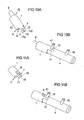
- FIG. 5 shows a gas guide element according to the FIG. 4 after mounting on a gas generator 4.
- the gas generator 4 is designed as a tubular gas generator and accordingly has a substantially cylindrical shape.
- two stud bolts 41, 42 are welded firmly.
- the studs 41, 42 are used to attach the gas generator 4 to a vehicle structure such as the frame of a vehicle seat or the vehicle chassis or the attachment of the gas generator 4 to a support member which is connected to such a vehicle structure. They have in all the illustrated embodiments preferably a screw, so that the bayonet lock can be additionally secured by a nut screwed.
- the gas guide 1 in the FIG. 5 at its end facing away from the gas generator 4 - unlike in the FIG. 4 shown - is designed as Gasleitrohr with a plurality of laterally formed in the peripheral wall 13 gas outlet openings 16.
- the area of Gas guide 1, which serves to connect to the gas generator 4, however, is according to the FIG. 4 educated.
- the bayonet lock is additionally secured by a nut 6, which is mounted on the threaded bolt 41, as in the FIG. 6 is shown schematically. In this case, the locking tab 3 turns straight when the nut 6 is tightened. As a result, the gas guide element 1 is additionally fixed to the threaded bolt 41.
- the gas-conducting element 1 is designed as a gas-conducting tube
- the gas-conducting tube 1 takes over 100% of the gas distribution.
- the Gasleitrohr 1 thus sits tightly on the gas generator 4 and exiting gas flows only in the pipe.
- Such Gasleitrohr can be used for example in door-integrated gas bag modules for head protection or for head and thorax protection.
- tubular gas generator 4 forms a gas outlet stub 45, on which gas outflow openings 46 are formed in a radial and thrust-neutral manner.
- the gas flow flowing out of the gas outlet openings 46 in the radial direction is diverted through the gas-conducting element 1 and directed into a gas bag (not shown).
- the gas outlet pipe 45 protrudes into the gas-conducting element 1.
- the gas-tightness of the connection between the gas guide 1 and the gas generator 4 adapted to the requirements.
- a complete gas-tightness or alternatively a defined partial gas flow which flows out of the gas-conducting element 1 in the connection region with the gas generator 4 can be provided.
- FIGS. 7A, 7B is as in the embodiment of FIG. 2 formed on the gas guide 1 a tab 15 which has two mirror-symmetrical tab portions 15a, 15b.
- the axis of symmetry and folding edge 152 does not extend in the circumferential direction, but obliquely. In principle, any angle can be realized.
- the two mirror-symmetrical flap parts 15a, 15b are hinged about an axially extending symmetry axis and folding edge 153.
- the FIG. 8B shows the folded state and the reinforcement formed by the superimposed flap portions 15a, 15b.
- the folded parts 15a, 15b can be additionally connected to each other by point connections 155.
- Such point connections 155 may be provided, for example, by spot welding. They allow a greater power transmission in the area of the stud with a small area and minimum material thickness of the gas guide.
- FIG. 9A a variant is shown, in which a flap 15 'of the gas guiding element, which is provided to provide a joining channel 2 of a bayonet closure, an identically shaped flap portion 15 "is placed as material Doppler and suitably fixed FIG. 9B represented, for example, again via point connections 155, which are made for example by welding.
- the result is a reinforced flap 15.
- FIGS. 10A to 13 Embodiments of a gas guide are described, which is not connected by means of a bayonet closure with a gas generator, but by sliding on a gas generator and additional fixing.
- a gas guide element 1 is provided which is tubular between a first end 11 and a second end 12 is and has a provided with an inner bore 14 peripheral wall 13.
- a Vorfix istselement 7 is arranged frontally, which serves for the connection and pre-fixing of the gas guide element 1 to a stud of the gas generator.
- the Vorfix istselement 7 has two substantially axially extending, parallel latching arms 71, 72 which form an elongated recess 73 between them.
- the front ends of the latching arms 71, 72 in this case have inwardly projecting projections 710, 720, which narrow the recess 73 in this area.
- a catching lug 8 likewise projecting from the front side, is provided, which is intended to be suspended in a module carrier or in an airbag and thereby additionally fix the gas-conducting element 1 axially in relation to the gas generator 4.
- FIG. 10B shows the gas guide the Figure 10A in mounted on a tube gas generator 4 with studs 41, 42 state.
- the connection is formed by axially pushing the gas guide element 1 on the gas generator 4, wherein the stud bolt 41 is inserted into the recess 73.
- the latching arms 71, 72 of the Vorfixtechniksijns 7 thereby encompass the one stud bolt 41 of the gas generator 4 and thus provide a prefixing and locking the gas guide element 1 on the gas generator 4 ready.
- This prefixing is in one embodiment by means of a nut corresponding to the nut 6 of FIG. 6 additionally secured.
- the gas guide is additionally fixed by means of the Einhticianlasche 8 by hanging on a module carrier or gas bag.
- FIG. 12 schematically illustrates the gas-conducting element 1, the latching arms 71, 72, the gas generator 4 and the stud bolts 41, 42.
- the Ein vonsche 8 passes through an opening 91 of a fixed or flexible structure 9, which for example, a module carrier of a gas bag module, of which the gas generator 4 and the gas guide 1 form a part, or a fastening element of a gas generator is.
- the suspension lug 8 is passed through the opening 91 of the module carrier 9.
- the Ein vonsche 8 performed by the gas bag in total or in one or more gas bag layers of the Gas bags can be introduced.
- the suspension lug 8 is preferably suspended in a region of the gas bag which remains locally unchanged during inflation of the gas bag.
- FIGS 11A and 11B show an alternative embodiment of a gas-conducting element, which on the one hand has a Vorfix michselement 7 and on the other hand a Ein mentallasche 8.
- the Ein rehabilitationlasche 8 is the Ein rehabilitationlasche 8 as well as the Vorfix michselement 7 formed at the first end 11 of the gas guide element 1 and formed by folding back a frontally projecting tab. This results in the same time, the elongated recess 73 between the latching arms 71, 72nd
- the corresponding suspension is in the FIG. 13 exemplified and shown schematically. It's like in the FIG. 12 schematically the gas guide 1, the latching arms 71, 72, the gas generator 4 and the studs 41, 42 shown.
- the arranged at the first end 11 of the gas guide 1 and folded back hanger tab 8 is passed through an opening 91 of a fixed or flexible structure 9 and thereby secures the gas guide 1 in the axial direction.
- the structure 9 may be, for example, a module carrier of a gas bag module or a fastening element of a gas generator or an airbag, in the latter case the suspension strap being able to be carried through the airbag as a whole or inserted into one or more airbag layers.
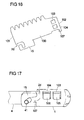
- FIGS. 14 to 17 show a further embodiment of a sleeve-shaped gas guide element 1, which is connectable by means of a bayonet closure with a stud of a gas generator.
- the sleeve-shaped gas guide element 1 is characterized by a in the FIG. 16 formed, for example, produced by punching metal blank 100 formed, which is rolled up to form the gas guide 1. It is provided that the two extending in the axial direction longitudinal edges 101, 102 of the blank are not firmly connected to each other, but overlap each other and thereby how a coil spring can move relative to each other.
- the overlapping area of the two longitudinal edges 101, 102 is, for example, 40 ° to 60 °.
- the blank 100 further includes a tab 15 similar to the flap 15 of FIG. 2 on, in which a slot-shaped recess 2d is designed for the realization of a joining channel of a bayonet closure.
- the blank 100 adjacent to the longitudinal edge 102 forms a latching nose 107.
- this locking lug 107 is due to the spring-like configuration of the gas guide element in the circumferential direction according to the arrow A movable. It protrudes into the joining channel 2d.
- the nose 107 can spring back upon insertion of the stud 41, so that the stud bolt 41 can be brought to its intended end position. Subsequently, the nose 107 springs back, so that the stud bolt 41 is locked. Because the latch 107 can not or only very little spring back in the opposite direction, since such a movement is blocked by the projections 105, 106.
- FIG. 17 shows in perspective from above the connected to the gas generator 4 by means of a bayonet closure gas guide element 1, which secures the stud 41 in the joining channel 2d by the latch 107.
- the Figure 18A shows a sectional view of the gas guide 1 of the FIG. 14 wherein the cut takes place in a region in which the one punch-out 104 and the corresponding projection 106 are realized. It can be seen that the protrusion 106, which protrudes in the manner of a tab, is set outwards and accordingly projects outwards. The same applies to the projection 105 and the punching 103rd
- FIG. 18B shows an alternative embodiment, which basically according to FIGS. 14 to 17 is formed, in which the overlapping portion, however, is directed inwards.
- the cutout 104 is located in the inner arch.
- the tab-like projection 106 which engages through the punch 104, is from the outer arc in the guided inside bow. So he protrudes through the punch 104 inside. The same applies to the projection 105 and the punching 103rd
- an advantage of this embodiment is that due to their inside arrangement, a deploying gas bag can not be damaged by the projections 105, 106.
- the projections 105, 106 may be sized so that when flowing gas from the gas generator 4 in the gas guide 1 and an associated force on the formed by the projections 105, 106 and recesses 103, 104 form-fitting connections to at least one Partial erecting of the projections 105, 106 may lead, so erected inwardly projecting projections 105, 106 are then supported on a disposed within the gas guide 1 gas generator 4, so that an improved support on the gas generator 4 is realized.
- FIG. 19 shows a variant in which in the region of the joining channel 2, which serves to guide the stud bolt 41 of the gas generator 4, a resilient tongue 108 is formed with, in order to lock the stud bolt 41 in its final position.
- the resilient tongue 108 is formed adjacent to the end position of the stud bolt 41 in the joining channel 2. It is punched, for example, from the surrounding material and shaped accordingly.
- the stud bolt 41 can be joined in a simple manner with normal manual force. However, the reverse path is blocked by the spring-biased tongue 108.
- FIG. 19 is the resilient tongue 108 on a tab 15 (corresponding to the tab 15 of FIG. 2 or the tab 15 of the FIGS. 13 to 17 ) are formed. It blocks the stay bolt of the gas generator after it has been brought into its final position in the joining channel 2.
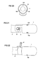
- FIGS. 20 to 22 relate to embodiments in which a sleeve-shaped gas guide element 1 is connected by means of bayonet closure with a tube gas generator 4.
- one or more local impressions 130 are introduced into the peripheral wall 13 of the gas guide element 1, which protrude into the interior of the sleeve 1.
- the local impressions 130 are thereby introduced into the sleeve-shaped gas guide element 1 before it is placed on the gas generator 4.
- At the gas generator 4 is no provided the local Inpresseptept 130 corresponding counter profile; Rather, its lateral surface is cylindrical in the usual way.
- the local indentations 130 represent punctual constrictions. They serve for additional fixing of the gas-conducting element 1 on the gas generator 4 and act as anti-tilting device during the outflow process of the gas. A tilting of the gas guide element 1 relative to the gas generator 4 is thus prevented.
- the end of the gas-conducting element 1, which is connected to the gas generator 4 is not gas-tight, since gas can flow past the local indentations 130 laterally.
- the other end of the gas guide element 1 may be open or closed.
- FIG. 21 shows the gas guide the FIG. 20 mounted on a gas generator 4.
- two of three local indentations 130 can be seen, which act as anti-tilt device.
- the number of local indentations 130 may vary. In the embodiment of FIG. 22 only a single local injection 130 is provided. This is opposite, ie offset by 180 ° to the stud 41 formed in the gas guide 1. This also achieves a tilt protection.
- the gas guide element 1 instead of puncture constrictions on linear constrictions, which can be axial, radial and / or oblique.
- One or more of such line-shaped constrictions may be provided.
- a gas tightness could also be provided at the end of the gas guide element 1 connected to the gas generator.
- the gas guide element according to the invention is used in one embodiment in a side airbag module, in particular in a side airbag module with a two-chamber side airbag, wherein the gas guide is designed such that it is deflected from the gas generator gas flowing in two directions.
Claims (11)
- Dispositif pour un système de protection de personne d'un véhicule, qui présente :- un générateur de gaz (4) qui est réalisé et prévu afin de mettre à disposition, en cas de déclenchement, du gaz pour le gonflage d'un sac de gaz, le générateur de gaz (4) présentant au moins un goujon (41, 42) agencé fixement et dépassant de la surface enveloppe du générateur de gaz (4),- un élément conducteur de gaz (1) en forme de douille relié au générateur de gaz (4) qui est réalisé et prévu afin de dévier du gaz sortant du générateur de gaz (4) et de le conduire dans un sac de gaz à gonfler,- l'élément conducteur de gaz (1) étant relié à l'aide d'une fermeture à baïonnette à au moins l'un des goujons (41) du générateur de gaz (4),- l'élément conducteur de gaz (1) réalisant pour la formation d'une fermeture à baïonnette au moins un canal d'assemblage (2, 2a, 2b, 2c, 2d) pour l'au moins un goujon (41) du générateur de gaz (4), et- l'élément conducteur de gaz (1) étant formé dans la zone, dans laquelle il forme le canal d'assemblage (2), au moins en partie par une languette (15) dépassant axialement de la paroi périphérique (13) de l'élément conducteur de gaz (1), caractérisé en ce que
le générateur de gaz (4) est réalisé de manière oblongue, en ce que l'élément conducteur de gaz (1) présente des moyens (107, 108, 3, 30) pour le verrouillage de la fermeture à baïonnette et en ce que les moyens pour le verrouillage de la fermeture à baïonnette comportent une languette (30) pliable agencée sur l'élément conducteur de gaz (1), à l'aide de laquelle la fermeture à baïonnette peut être bloquée après l'atteinte de la position finale du goujon (41) par repliage de la languette (30). - Dispositif selon la revendication 1, caractérisé en ce que le canal d'assemblage (2b) se compose exclusivement d'une zone (22b) qui s'étend sensiblement transversalement à l'axe longitudinal de l'élément conducteur de gaz (1) et qui est réalisée sur une partie en saillie (15) de l'élément conducteur de gaz (1).
- Dispositif selon la revendication 1 ou 2, caractérisé en ce que les moyens pour le verrouillage de la fermeture à baïonnette comportent un nez d'encliquetage (107, 108) qui est réalisé ou agencé de manière élastique sur l'élément conducteur de gaz (1) et qui arrête le goujon (41) après l'atteinte de sa position finale dans la fermeture à baïonnette.
- Dispositif selon l'une quelconque des revendications précédentes, caractérisé en ce que les moyens pour le verrouillage de la fermeture à baïonnette comportent une languette (3) agencée sur l'élément conducteur de gaz (1), qui pénètre dans l'état non monté en biais à l'intérieur de l'élément conducteur de gaz (1) et qui s'oriente de manière droite lors du placement d'un écrou (6) sur le goujon (4) et du serrage de l'écrou (6) et fixe en outre l'élément conducteur de gaz (1) sur le générateur de gaz (4).
- Dispositif selon l'une quelconque des revendications précédentes, caractérisé en ce que l'élément conducteur de gaz (1) présente, dans la zone dans laquelle il forme le canal d'assemblage (2), au moins en partie un renforcement de matériau.
- Dispositif selon la revendication 5, caractérisé en ce que la languette (15) est formée par rabattement l'une sur l'autre au moins de deux parties de languette (15a, 15b) ou une doubleuse de matériau (15") est agencée sur la languette (15) de sorte que la languette (15) présente par rapport à la paroi périphérique (13) de l'élément conducteur de gaz (1) une épaisseur de matériau accrue.
- Dispositif pour un système de protection de personne d'un véhicule, qui présente :- un générateur de gaz (4) qui est réalisé et prévu afin de mettre à disposition, en cas de déclenchement, du gaz pour le gonflage d'un sac de gaz, le générateur de gaz (4) présentant au moins un goujon (41, 42) agencé fixement et dépassant de la surface enveloppe du générateur de gaz (4),- un élément conducteur de gaz (1) en forme de douille relié au générateur de gaz (4) qui est réalisé et prévu afin de dévier du gaz sortant du générateur de gaz (4) et de le conduire dans un sac de gaz à gonfler,- l'élément conducteur de gaz (1) présentant au moins un évidement (73), dans lequel un goujon (41) du générateur de gaz (4) est introduit lors du coulissement de l'élément conducteur de gaz (1) dans le sens axial sur le générateur de gaz (4), ainsi qu'au moins un élément de blocage (8) qui est prévu et réalisé afin d'être suspendu dans une autre structure (9) et de bloquer ce faisant l'élément conducteur de gaz (1) en outre dans le sens axial sur le générateur de gaz (4),
caractérisé en ce que
le générateur de gaz (4) est réalisé de manière oblongue et en ce que l'élément de blocage (8) est formé par une languette de suspension, l'extrémité de la languette de suspension étant dirigée dans une direction qui est opposée du générateur de gaz (4). - Dispositif selon la revendication 7, caractérisé en ce que l'évidement (73) est réalisé sur une partie (7) dépassant axialement de la paroi périphérique (13) de l'élément conducteur de gaz (1).
- Dispositif selon la revendication 7 ou 8, caractérisé en ce que l'évidement (73) est réalisé dans une partie (7) qui s'étend à partir de sa liaison avec la paroi périphérique (13) de l'élément conducteur de gaz (1) dans un premier sens et l'élément de blocage (8) s'étend à partir de sa liaison avec la paroi périphérique (13) de l'élément conducteur de gaz (1) dans un second sens, le premier sens et le second sens étant opposés.
- Dispositif pour un système de protection de personne d'un véhicule qui présente :- un générateur de gaz (4) qui est réalisé et prévu afin de mettre à disposition, en cas de déclenchement, du gaz pour le gonflage d'un sac de gaz, le générateur de gaz (4) présentant au moins un goujon (41, 42) agencé fixement et dépassant de la surface enveloppe du générateur de gaz (4),- un élément conducteur de gaz (1) en forme de douille relié au générateur de gaz (4) qui est réalisé et prévu afin de dévier du gaz sortant du générateur de gaz (4) et de le conduire dans un sac de gaz à gonfler,- l'élément conducteur de gaz (1) présentant un canal d'assemblage (2b) s'étendant sensiblement transversalement, dans lequel au moins l'un des goujons (41) du générateur de gaz (4) peut être introduit par un mouvement de rotation s'effectuant dans le sens périphérique, le canal d'assemblage (2b) étant réalisé au moins en partie sur une partie (15) en saillie axiale côté avant de l'élément conducteur de gaz (1), caractérisé en ce que
le générateur de gaz (4) est réalisé de manière oblongue et en ce que la partie en saillie (15) présente une languette (30) pliable ou flexible, à l'aide de laquelle le canal d'assemblage (2b) peut être fermé après l'introduction du goujon (41) dans le canal d'assemblage (2b). - Dispositif selon la revendication 10, caractérisé en ce que la partie en saillie (15) est formée par rabattement d'une zone partielle (15a) découpée dans le flan de matériau (20) étendu à plat de l'élément conducteur de gaz (1) qui est reliée uniquement par un axe de rabattement (151) s'étendant dans le sens axial au flan de matériau (20), sur une zone partielle (15b) réalisée de manière sensiblement symétrique à celle-ci du flan de matériau (20), des zones (22b) du canal d'assemblage (2b) s'étendant transversalement dans les deux zones partielles (15a, 15b) étant réalisées, lesquelles viennent l'une sur l'autre après le rabattement d'une zone partielle (15a) sur l'autre zone partielle (15b).
Applications Claiming Priority (2)
| Application Number | Priority Date | Filing Date | Title |
|---|---|---|---|
| DE102010039902A DE102010039902A1 (de) | 2010-08-27 | 2010-08-27 | Vorrichtungen für Personen-Schutzsysteme eines Fahrzeugs |
| PCT/EP2011/062577 WO2012025317A1 (fr) | 2010-08-27 | 2011-07-21 | Dispositifs pour systèmes de protection de personnes d'un véhicule |
Publications (2)
| Publication Number | Publication Date |
|---|---|
| EP2608991A1 EP2608991A1 (fr) | 2013-07-03 |
| EP2608991B1 true EP2608991B1 (fr) | 2015-08-26 |
Family
ID=44630119
Family Applications (1)
| Application Number | Title | Priority Date | Filing Date |
|---|---|---|---|
| EP11743218.7A Active EP2608991B1 (fr) | 2010-08-27 | 2011-07-21 | Dispositifs pour systèmes de protection de personnes d'un véhicule |
Country Status (5)
| Country | Link |
|---|---|
| US (1) | US8764050B2 (fr) |
| EP (1) | EP2608991B1 (fr) |
| JP (1) | JP5957453B2 (fr) |
| DE (1) | DE102010039902A1 (fr) |
| WO (1) | WO2012025317A1 (fr) |
Families Citing this family (25)
| Publication number | Priority date | Publication date | Assignee | Title |
|---|---|---|---|---|
| JP5933236B2 (ja) * | 2011-11-29 | 2016-06-08 | オートリブ ディベロップメント エービー | ガス供給装置およびエアバッグ装置 |
| JP5943729B2 (ja) * | 2012-06-13 | 2016-07-05 | タカタ株式会社 | インフレータ装置及びそれを備えるエアバッグ装置 |
| JP5949521B2 (ja) * | 2012-06-26 | 2016-07-06 | 豊田合成株式会社 | ガス発生装置及びエアバッグ装置 |
| JP5915482B2 (ja) | 2012-09-27 | 2016-05-11 | 豊田合成株式会社 | エアバッグ装置の中間組付け体及びエアバッグ装置の組付け方法 |
| KR102064002B1 (ko) * | 2013-05-07 | 2020-01-08 | 현대모비스 주식회사 | 차량의 사이드 에어백 |
| US9618704B2 (en) * | 2013-07-31 | 2017-04-11 | Corning Optical Communications LLC | Fiber optic connector sub-assemblies having a front-loading locking ferrule holder and related fiber optic components, devices and methods |
| CN104490023B (zh) * | 2014-12-18 | 2017-05-03 | 赵威 | 互换式扭钉首饰锁扣 |
| FR3031245B1 (fr) * | 2014-12-24 | 2016-12-23 | Radiall Sa | Ensemble de connexion a verrouillage par baionnette des elements de connexion |
| DE102015205429B4 (de) | 2015-03-25 | 2020-06-04 | Joyson Safety Systems Germany Gmbh | Gasleitelement und Verfahren zum Herstellen einer Gasgeneratoranordnung |
| JP6500274B2 (ja) * | 2015-09-01 | 2019-04-17 | 豊田合成株式会社 | エアバッグ |
| US10018000B2 (en) * | 2016-02-25 | 2018-07-10 | Michael Brent Ford | Latch assembly for a pumping system and method therefor |
| DE102016104103A1 (de) * | 2016-03-07 | 2017-09-07 | Takata AG | Gasgeneratoranordnung und Verfahren zum Herstellen einer Gasgeneratoranordnung |
| CN107605888B (zh) * | 2017-09-08 | 2019-07-26 | 佛山市爵顿家居科技有限公司 | 免焊接金属构件连接方法及金属构件 |
| DE102019100262A1 (de) | 2018-10-02 | 2020-04-02 | Trw Automotive Gmbh | Baugruppe aus einem Diffusor und einem Gasgenerator, Gassackmodul und Verfahren zur Montage einer Baugruppe |
| DE102019122987A1 (de) * | 2019-08-27 | 2021-03-04 | Zf Airbag Germany Gmbh | Diffusor für einen Gasgenerator, Gasgenerator mit einem solchen Diffusor und Herstellungsverfahren für einen solchen Diffusor |
| DE102019122992A1 (de) * | 2019-08-27 | 2021-03-04 | Zf Airbag Germany Gmbh | Baugruppe aus einer Abdeckkappe eines Rohrgasgenerators und einem Deflektorelement, Rohrgasgenerator und Verfahren zur Herstellung eines Rohrgasgenerators |
| CN110723098B (zh) * | 2019-10-14 | 2021-02-26 | 华懋(厦门)新材料科技股份有限公司 | 一种安全气囊气体发生器的外套壳组件 |
| US11279317B2 (en) * | 2019-12-09 | 2022-03-22 | Autoliv Asp, Inc. | Gas generator of an inflatable airbag, the gas generator including a diffuser for diffusing inflation gases |
| US11345424B2 (en) * | 2020-07-02 | 2022-05-31 | Steven G. Weiss | Device for attaching a bottle to prevent accidental release |
| US11623599B2 (en) * | 2021-04-09 | 2023-04-11 | ZF Passive Safety Systems US Inc. | Airbag with inflator attachment |
| US11299120B1 (en) * | 2021-04-15 | 2022-04-12 | Autoliv Asp, Inc. | Side airbag assemblies and methods of assembly |
| US11708043B2 (en) * | 2021-04-20 | 2023-07-25 | Autoliv Asp, Inc. | Inflator bracket |
| US11718263B2 (en) * | 2021-09-02 | 2023-08-08 | ZF Passive Safety Systems US Inc. | Fill tube adaptor for inflator |
| TWI803352B (zh) * | 2022-06-14 | 2023-05-21 | 元翊精密工業股份有限公司 | 具有快拆接頭的氣體發生器及其組裝方法 |
| TWI822110B (zh) * | 2022-06-14 | 2023-11-11 | 元翊精密工業股份有限公司 | 個人防護裝置 |
Citations (1)
| Publication number | Priority date | Publication date | Assignee | Title |
|---|---|---|---|---|
| DE29815940U1 (de) * | 1998-09-04 | 1998-10-15 | Trw Automotive Safety Sys Gmbh | Mittel zur Befestigung eines Gasgenerators in einem Airbagmodul |
Family Cites Families (28)
| Publication number | Priority date | Publication date | Assignee | Title |
|---|---|---|---|---|
| US2181495A (en) * | 1939-06-26 | 1939-11-28 | Novack Henry | Platform nest for birds |
| JP3114396B2 (ja) * | 1992-10-30 | 2000-12-04 | タカタ株式会社 | エアバッグ装置のインフレ−タ取付構造 |
| JP3114395B2 (ja) * | 1992-10-30 | 2000-12-04 | タカタ株式会社 | エアバッグ装置のインフレータ取付構造 |
| JP3015655B2 (ja) * | 1994-03-15 | 2000-03-06 | 株式会社東海理化電機製作所 | エアバッグ装置 |
| DE9408908U1 (de) * | 1994-05-31 | 1994-11-17 | Trw Repa Gmbh | Gassack-Schutzvorrichtung |
| US5913536A (en) * | 1996-02-07 | 1999-06-22 | Trw Vehicle Safety System Inc. | Air bag module |
| DE19743615B4 (de) * | 1997-10-02 | 2006-02-02 | ZF Lemförder Metallwaren AG | Airbagbaueinheit |
| DE29801104U1 (de) | 1998-01-23 | 1998-05-20 | Trw Repa Gmbh | Gasgenerator |
| US6059311A (en) * | 1998-02-21 | 2000-05-09 | Breed Automotive Technology, Inc. | Pillar-mounted side impact and rollover air bag |
| DE10027240B4 (de) | 2000-05-31 | 2016-11-17 | Autoliv Development Ab | Luftsackmodul für Kraftfahrzeuge |
| JP4181997B2 (ja) | 2002-01-04 | 2008-11-19 | タカターペトリ(ウルム)ゲーエムベーハー | 側方エアバッグモジュールのためのガス流分配器 |
| DE10211232B4 (de) | 2002-03-13 | 2005-12-08 | Autoliv Development Ab | Gasleitvorrichtung für eine Airbaganordnung |
| DE20215115U1 (de) * | 2002-10-01 | 2003-02-20 | Trw Automotive Safety Sys Gmbh | Gassackmodul |
| US20040150202A1 (en) * | 2002-11-18 | 2004-08-05 | Yuzo Goto | Inflator for air bag |
| DE10339523B4 (de) | 2003-08-21 | 2017-10-19 | TAKATA Aktiengesellschaft | Airbagmodul mit Gasgenerator und mit mindestens einem hülsenförmigen Massenstromverteiler |
| DE102005004286A1 (de) | 2005-01-28 | 2006-08-10 | Zf Friedrichshafen Ag | Airbagbaueinheit |
| JP4898826B2 (ja) | 2005-12-01 | 2012-03-21 | タカタ・ペトリ アーゲー | エアバッグ装置 |
| DE102006013990A1 (de) * | 2006-03-22 | 2007-09-27 | Takata-Petri Ag | Befestigungsanordnung in einem Airbagmodul |
| JP5199604B2 (ja) | 2006-06-12 | 2013-05-15 | タカタ株式会社 | 側突用エアバッグ装置、車両用シート、インフレータのガス分配器 |
| US20080007035A1 (en) | 2006-06-26 | 2008-01-10 | Trw Automotive Gmbh | Airbag module |
| ATE455680T1 (de) * | 2006-10-16 | 2010-02-15 | Autoliv Dev | Airbag mit einer flexiblen befestigungslasche |
| JP4780021B2 (ja) * | 2007-04-02 | 2011-09-28 | 豊田合成株式会社 | 頭部保護エアバッグ装置 |
| US7479033B1 (en) * | 2007-07-23 | 2009-01-20 | Tyco Electronics Corporation | High performance coaxial connector |
| JP2009040229A (ja) | 2007-08-09 | 2009-02-26 | Takata Corp | 側突用エアバッグ装置 |
| US7938436B2 (en) * | 2008-01-29 | 2011-05-10 | Autoliv Asp, Inc. | Slide-on inflator housing |
| DE102009006077B4 (de) * | 2009-01-26 | 2015-04-02 | Autoliv Development Ab | Gassackeinheit |
| WO2010131326A1 (fr) | 2009-05-11 | 2010-11-18 | トヨタ自動車株式会社 | Dispositif de coussin de sécurité gonflable latéral pour véhicule |
| DE102009031120B4 (de) * | 2009-06-30 | 2017-07-27 | GM Global Technology Operations LLC (n. d. Ges. d. Staates Delaware) | Airbageinrichtung für ein Kraftfahrzeug |
-
2010
- 2010-08-27 DE DE102010039902A patent/DE102010039902A1/de not_active Ceased
-
2011
- 2011-07-21 WO PCT/EP2011/062577 patent/WO2012025317A1/fr active Application Filing
- 2011-07-21 JP JP2013525209A patent/JP5957453B2/ja not_active Expired - Fee Related
- 2011-07-21 EP EP11743218.7A patent/EP2608991B1/fr active Active
-
2013
- 2013-02-25 US US13/775,612 patent/US8764050B2/en not_active Expired - Fee Related
Patent Citations (1)
| Publication number | Priority date | Publication date | Assignee | Title |
|---|---|---|---|---|
| DE29815940U1 (de) * | 1998-09-04 | 1998-10-15 | Trw Automotive Safety Sys Gmbh | Mittel zur Befestigung eines Gasgenerators in einem Airbagmodul |
Also Published As
| Publication number | Publication date |
|---|---|
| US8764050B2 (en) | 2014-07-01 |
| WO2012025317A1 (fr) | 2012-03-01 |
| DE102010039902A1 (de) | 2012-03-01 |
| JP2013536121A (ja) | 2013-09-19 |
| EP2608991A1 (fr) | 2013-07-03 |
| JP5957453B2 (ja) | 2016-07-27 |
| US20130161946A1 (en) | 2013-06-27 |
Similar Documents
| Publication | Publication Date | Title |
|---|---|---|
| EP2608991B1 (fr) | Dispositifs pour systèmes de protection de personnes d'un véhicule | |
| EP1954536B1 (fr) | Distributeur de courant de gaz pour un module poche de gaz | |
| EP2203330B1 (fr) | Module airbag | |
| DE102013008467B4 (de) | Befestigungsvorrichtung für einen gefalteten Gassack | |
| DE102014008973A1 (de) | Gassackmodul | |
| WO2015028518A1 (fr) | Agencement d'un élément de fixation sur une patte de fixation d'un coussin à gaz et son procédé de fabrication | |
| EP1492687A1 (fr) | Unite de sac gonflable de securite comportant un element de maintien et un element support destine a la fixation du sac de gaz | |
| WO2018077714A1 (fr) | Module d'airbag | |
| WO2005076687A2 (fr) | Sac gonflable et module de sac gonflable | |
| DE102011004049A1 (de) | Vorrichtung zur Anordnung eines Befestigungselementes an einer Befestigungslasche eines Gassacks eines Fahrzeuginsassen-Rückhaltesystems | |
| DE102006061617A1 (de) | Befestigungsanordnung, insbesondere zum Halten eines Umlenkbeschlags für einen Gurtbandabschnitt eines Sicherheitsgurtes in einem Fahrzeug, sowie Verfahren zum Befestigen eines Umlenkbeschlags an einer Trägerwand | |
| DE102005042026A1 (de) | Vorhanggassack-Einheit | |
| WO2010129973A1 (fr) | Colonne de direction pour un véhicule à moteur | |
| WO2018077715A1 (fr) | Module de coussin gonflable | |
| WO2005080147A1 (fr) | Unite generatrice de gaz pour module de sac a gaz | |
| DE10339523B4 (de) | Airbagmodul mit Gasgenerator und mit mindestens einem hülsenförmigen Massenstromverteiler | |
| WO2016180523A1 (fr) | Module airbag et ensemble | |
| DE202014006709U1 (de) | Gassackmodul | |
| DE102015205429B4 (de) | Gasleitelement und Verfahren zum Herstellen einer Gasgeneratoranordnung | |
| DE19653175A1 (de) | Gassackrückhalteeinrichtung für ein Kraftfahrzeug | |
| EP0849125B1 (fr) | Couvercle pour un système de retenue par coussin de sécurité | |
| DE102009045739B4 (de) | Diffusor für eine Gassackvorrichtung eines Fahrzeuginsassen-Rückhaltesystems und Gassackvorrichtung mit einem Diffusor | |
| DE10033173C1 (de) | Gassackmodul mit Halteplatte für den Gassack | |
| DE102015109253A1 (de) | Rohrschelle | |
| WO2023156646A1 (fr) | Module airbag latéral destiné à être fixé sur un cadre d'un dossier de siège, son procédé de fixation et siège de véhicule doté dudit module airbag latéral |
Legal Events
| Date | Code | Title | Description |
|---|---|---|---|
| PUAI | Public reference made under article 153(3) epc to a published international application that has entered the european phase |
Free format text: ORIGINAL CODE: 0009012 |
|
| 17P | Request for examination filed |
Effective date: 20130321 |
|
| AK | Designated contracting states |
Kind code of ref document: A1 Designated state(s): AL AT BE BG CH CY CZ DE DK EE ES FI FR GB GR HR HU IE IS IT LI LT LU LV MC MK MT NL NO PL PT RO RS SE SI SK SM TR |
|
| DAX | Request for extension of the european patent (deleted) | ||
| 17Q | First examination report despatched |
Effective date: 20140616 |
|
| GRAP | Despatch of communication of intention to grant a patent |
Free format text: ORIGINAL CODE: EPIDOSNIGR1 |
|
| INTG | Intention to grant announced |
Effective date: 20150324 |
|
| GRAS | Grant fee paid |
Free format text: ORIGINAL CODE: EPIDOSNIGR3 |
|
| GRAA | (expected) grant |
Free format text: ORIGINAL CODE: 0009210 |
|
| AK | Designated contracting states |
Kind code of ref document: B1 Designated state(s): AL AT BE BG CH CY CZ DE DK EE ES FI FR GB GR HR HU IE IS IT LI LT LU LV MC MK MT NL NO PL PT RO RS SE SI SK SM TR |
|
| REG | Reference to a national code |
Ref country code: GB Ref legal event code: FG4D Free format text: NOT ENGLISH |
|
| REG | Reference to a national code |
Ref country code: CH Ref legal event code: EP |
|
| REG | Reference to a national code |
Ref country code: AT Ref legal event code: REF Ref document number: 744983 Country of ref document: AT Kind code of ref document: T Effective date: 20150915 |
|
| REG | Reference to a national code |
Ref country code: IE Ref legal event code: FG4D Free format text: LANGUAGE OF EP DOCUMENT: GERMAN |
|
| REG | Reference to a national code |
Ref country code: DE Ref legal event code: R096 Ref document number: 502011007706 Country of ref document: DE |
|
| REG | Reference to a national code |
Ref country code: LT Ref legal event code: MG4D |
|
| PG25 | Lapsed in a contracting state [announced via postgrant information from national office to epo] |
Ref country code: FI Free format text: LAPSE BECAUSE OF FAILURE TO SUBMIT A TRANSLATION OF THE DESCRIPTION OR TO PAY THE FEE WITHIN THE PRESCRIBED TIME-LIMIT Effective date: 20150826 Ref country code: LV Free format text: LAPSE BECAUSE OF FAILURE TO SUBMIT A TRANSLATION OF THE DESCRIPTION OR TO PAY THE FEE WITHIN THE PRESCRIBED TIME-LIMIT Effective date: 20150826 Ref country code: NO Free format text: LAPSE BECAUSE OF FAILURE TO SUBMIT A TRANSLATION OF THE DESCRIPTION OR TO PAY THE FEE WITHIN THE PRESCRIBED TIME-LIMIT Effective date: 20151126 Ref country code: LT Free format text: LAPSE BECAUSE OF FAILURE TO SUBMIT A TRANSLATION OF THE DESCRIPTION OR TO PAY THE FEE WITHIN THE PRESCRIBED TIME-LIMIT Effective date: 20150826 Ref country code: GR Free format text: LAPSE BECAUSE OF FAILURE TO SUBMIT A TRANSLATION OF THE DESCRIPTION OR TO PAY THE FEE WITHIN THE PRESCRIBED TIME-LIMIT Effective date: 20151127 |
|
| REG | Reference to a national code |
Ref country code: NL Ref legal event code: MP Effective date: 20150826 |
|
| PG25 | Lapsed in a contracting state [announced via postgrant information from national office to epo] |
Ref country code: PL Free format text: LAPSE BECAUSE OF FAILURE TO SUBMIT A TRANSLATION OF THE DESCRIPTION OR TO PAY THE FEE WITHIN THE PRESCRIBED TIME-LIMIT Effective date: 20150826 Ref country code: HR Free format text: LAPSE BECAUSE OF FAILURE TO SUBMIT A TRANSLATION OF THE DESCRIPTION OR TO PAY THE FEE WITHIN THE PRESCRIBED TIME-LIMIT Effective date: 20150826 Ref country code: PT Free format text: LAPSE BECAUSE OF FAILURE TO SUBMIT A TRANSLATION OF THE DESCRIPTION OR TO PAY THE FEE WITHIN THE PRESCRIBED TIME-LIMIT Effective date: 20151228 Ref country code: IS Free format text: LAPSE BECAUSE OF FAILURE TO SUBMIT A TRANSLATION OF THE DESCRIPTION OR TO PAY THE FEE WITHIN THE PRESCRIBED TIME-LIMIT Effective date: 20151226 Ref country code: SE Free format text: LAPSE BECAUSE OF FAILURE TO SUBMIT A TRANSLATION OF THE DESCRIPTION OR TO PAY THE FEE WITHIN THE PRESCRIBED TIME-LIMIT Effective date: 20150826 Ref country code: ES Free format text: LAPSE BECAUSE OF FAILURE TO SUBMIT A TRANSLATION OF THE DESCRIPTION OR TO PAY THE FEE WITHIN THE PRESCRIBED TIME-LIMIT Effective date: 20150826 Ref country code: RS Free format text: LAPSE BECAUSE OF FAILURE TO SUBMIT A TRANSLATION OF THE DESCRIPTION OR TO PAY THE FEE WITHIN THE PRESCRIBED TIME-LIMIT Effective date: 20150826 |
|
| PG25 | Lapsed in a contracting state [announced via postgrant information from national office to epo] |
Ref country code: NL Free format text: LAPSE BECAUSE OF FAILURE TO SUBMIT A TRANSLATION OF THE DESCRIPTION OR TO PAY THE FEE WITHIN THE PRESCRIBED TIME-LIMIT Effective date: 20150826 |
|
| PG25 | Lapsed in a contracting state [announced via postgrant information from national office to epo] |
Ref country code: SK Free format text: LAPSE BECAUSE OF FAILURE TO SUBMIT A TRANSLATION OF THE DESCRIPTION OR TO PAY THE FEE WITHIN THE PRESCRIBED TIME-LIMIT Effective date: 20150826 Ref country code: DK Free format text: LAPSE BECAUSE OF FAILURE TO SUBMIT A TRANSLATION OF THE DESCRIPTION OR TO PAY THE FEE WITHIN THE PRESCRIBED TIME-LIMIT Effective date: 20150826 Ref country code: CZ Free format text: LAPSE BECAUSE OF FAILURE TO SUBMIT A TRANSLATION OF THE DESCRIPTION OR TO PAY THE FEE WITHIN THE PRESCRIBED TIME-LIMIT Effective date: 20150826 Ref country code: IT Free format text: LAPSE BECAUSE OF FAILURE TO SUBMIT A TRANSLATION OF THE DESCRIPTION OR TO PAY THE FEE WITHIN THE PRESCRIBED TIME-LIMIT Effective date: 20150826 Ref country code: EE Free format text: LAPSE BECAUSE OF FAILURE TO SUBMIT A TRANSLATION OF THE DESCRIPTION OR TO PAY THE FEE WITHIN THE PRESCRIBED TIME-LIMIT Effective date: 20150826 |
|
| REG | Reference to a national code |
Ref country code: DE Ref legal event code: R097 Ref document number: 502011007706 Country of ref document: DE |
|
| PG25 | Lapsed in a contracting state [announced via postgrant information from national office to epo] |
Ref country code: RO Free format text: LAPSE BECAUSE OF FAILURE TO SUBMIT A TRANSLATION OF THE DESCRIPTION OR TO PAY THE FEE WITHIN THE PRESCRIBED TIME-LIMIT Effective date: 20150826 |
|
| PLBE | No opposition filed within time limit |
Free format text: ORIGINAL CODE: 0009261 |
|
| STAA | Information on the status of an ep patent application or granted ep patent |
Free format text: STATUS: NO OPPOSITION FILED WITHIN TIME LIMIT |
|
| 26N | No opposition filed |
Effective date: 20160530 |
|
| PG25 | Lapsed in a contracting state [announced via postgrant information from national office to epo] |
Ref country code: SI Free format text: LAPSE BECAUSE OF FAILURE TO SUBMIT A TRANSLATION OF THE DESCRIPTION OR TO PAY THE FEE WITHIN THE PRESCRIBED TIME-LIMIT Effective date: 20150826 |
|
| PG25 | Lapsed in a contracting state [announced via postgrant information from national office to epo] |
Ref country code: BE Free format text: LAPSE BECAUSE OF NON-PAYMENT OF DUE FEES Effective date: 20160731 |
|
| REG | Reference to a national code |
Ref country code: CH Ref legal event code: PL |
|
| GBPC | Gb: european patent ceased through non-payment of renewal fee |
Effective date: 20160721 |
|
| PG25 | Lapsed in a contracting state [announced via postgrant information from national office to epo] |
Ref country code: MC Free format text: LAPSE BECAUSE OF FAILURE TO SUBMIT A TRANSLATION OF THE DESCRIPTION OR TO PAY THE FEE WITHIN THE PRESCRIBED TIME-LIMIT Effective date: 20150826 |
|
| PG25 | Lapsed in a contracting state [announced via postgrant information from national office to epo] |
Ref country code: FR Free format text: LAPSE BECAUSE OF NON-PAYMENT OF DUE FEES Effective date: 20160801 Ref country code: CH Free format text: LAPSE BECAUSE OF NON-PAYMENT OF DUE FEES Effective date: 20160731 Ref country code: LI Free format text: LAPSE BECAUSE OF NON-PAYMENT OF DUE FEES Effective date: 20160731 |
|
| REG | Reference to a national code |
Ref country code: FR Ref legal event code: ST Effective date: 20170331 |
|
| REG | Reference to a national code |
Ref country code: IE Ref legal event code: MM4A |
|
| PG25 | Lapsed in a contracting state [announced via postgrant information from national office to epo] |
Ref country code: GB Free format text: LAPSE BECAUSE OF NON-PAYMENT OF DUE FEES Effective date: 20160721 |
|
| PG25 | Lapsed in a contracting state [announced via postgrant information from national office to epo] |
Ref country code: IE Free format text: LAPSE BECAUSE OF NON-PAYMENT OF DUE FEES Effective date: 20160721 |
|
| PG25 | Lapsed in a contracting state [announced via postgrant information from national office to epo] |
Ref country code: LU Free format text: LAPSE BECAUSE OF NON-PAYMENT OF DUE FEES Effective date: 20160721 |
|
| REG | Reference to a national code |
Ref country code: AT Ref legal event code: MM01 Ref document number: 744983 Country of ref document: AT Kind code of ref document: T Effective date: 20160721 |
|
| PG25 | Lapsed in a contracting state [announced via postgrant information from national office to epo] |
Ref country code: AT Free format text: LAPSE BECAUSE OF NON-PAYMENT OF DUE FEES Effective date: 20160721 |
|
| PG25 | Lapsed in a contracting state [announced via postgrant information from national office to epo] |
Ref country code: CY Free format text: LAPSE BECAUSE OF FAILURE TO SUBMIT A TRANSLATION OF THE DESCRIPTION OR TO PAY THE FEE WITHIN THE PRESCRIBED TIME-LIMIT Effective date: 20150826 Ref country code: SM Free format text: LAPSE BECAUSE OF FAILURE TO SUBMIT A TRANSLATION OF THE DESCRIPTION OR TO PAY THE FEE WITHIN THE PRESCRIBED TIME-LIMIT Effective date: 20150826 Ref country code: HU Free format text: LAPSE BECAUSE OF FAILURE TO SUBMIT A TRANSLATION OF THE DESCRIPTION OR TO PAY THE FEE WITHIN THE PRESCRIBED TIME-LIMIT; INVALID AB INITIO Effective date: 20110721 |
|
| PG25 | Lapsed in a contracting state [announced via postgrant information from national office to epo] |
Ref country code: TR Free format text: LAPSE BECAUSE OF FAILURE TO SUBMIT A TRANSLATION OF THE DESCRIPTION OR TO PAY THE FEE WITHIN THE PRESCRIBED TIME-LIMIT Effective date: 20150826 Ref country code: MK Free format text: LAPSE BECAUSE OF FAILURE TO SUBMIT A TRANSLATION OF THE DESCRIPTION OR TO PAY THE FEE WITHIN THE PRESCRIBED TIME-LIMIT Effective date: 20150826 Ref country code: MT Free format text: LAPSE BECAUSE OF FAILURE TO SUBMIT A TRANSLATION OF THE DESCRIPTION OR TO PAY THE FEE WITHIN THE PRESCRIBED TIME-LIMIT Effective date: 20150826 |
|
| PG25 | Lapsed in a contracting state [announced via postgrant information from national office to epo] |
Ref country code: BG Free format text: LAPSE BECAUSE OF FAILURE TO SUBMIT A TRANSLATION OF THE DESCRIPTION OR TO PAY THE FEE WITHIN THE PRESCRIBED TIME-LIMIT Effective date: 20150826 |
|
| REG | Reference to a national code |
Ref country code: DE Ref legal event code: R082 Ref document number: 502011007706 Country of ref document: DE Representative=s name: MAIKOWSKI & NINNEMANN PATENTANWAELTE PARTNERSC, DE Ref country code: DE Ref legal event code: R081 Ref document number: 502011007706 Country of ref document: DE Owner name: JOYSON SAFETY SYSTEMS GERMANY GMBH, DE Free format text: FORMER OWNER: TAKATA AG, 63743 ASCHAFFENBURG, DE |
|
| PG25 | Lapsed in a contracting state [announced via postgrant information from national office to epo] |
Ref country code: AL Free format text: LAPSE BECAUSE OF FAILURE TO SUBMIT A TRANSLATION OF THE DESCRIPTION OR TO PAY THE FEE WITHIN THE PRESCRIBED TIME-LIMIT Effective date: 20150826 |
|
| PGFP | Annual fee paid to national office [announced via postgrant information from national office to epo] |
Ref country code: DE Payment date: 20230726 Year of fee payment: 13 |