EP2608991B1 - Devices for passenger protection systems in a vehicle - Google Patents
Devices for passenger protection systems in a vehicle Download PDFInfo
- Publication number
- EP2608991B1 EP2608991B1 EP11743218.7A EP11743218A EP2608991B1 EP 2608991 B1 EP2608991 B1 EP 2608991B1 EP 11743218 A EP11743218 A EP 11743218A EP 2608991 B1 EP2608991 B1 EP 2608991B1
- Authority
- EP
- European Patent Office
- Prior art keywords
- gas
- conducting element
- gas generator
- tab
- generator
- Prior art date
- Legal status (The legal status is an assumption and is not a legal conclusion. Google has not performed a legal analysis and makes no representation as to the accuracy of the status listed.)
- Active
Links
- 238000005304 joining Methods 0.000 claims description 60
- 239000000463 material Substances 0.000 claims description 33
- 230000002093 peripheral effect Effects 0.000 claims description 22
- 230000033001 locomotion Effects 0.000 claims description 20
- 230000002787 reinforcement Effects 0.000 claims description 10
- 238000005452 bending Methods 0.000 claims description 2
- 230000004913 activation Effects 0.000 claims 3
- 239000007789 gas Substances 0.000 description 324
- 206010053648 Vascular occlusion Diseases 0.000 description 11
- 239000000725 suspension Substances 0.000 description 11
- 238000003780 insertion Methods 0.000 description 9
- 230000037431 insertion Effects 0.000 description 9
- 238000007373 indentation Methods 0.000 description 5
- 239000002184 metal Substances 0.000 description 4
- 238000004080 punching Methods 0.000 description 4
- 238000003466 welding Methods 0.000 description 4
- 230000008901 benefit Effects 0.000 description 3
- 230000003321 amplification Effects 0.000 description 2
- 238000002347 injection Methods 0.000 description 2
- 239000007924 injection Substances 0.000 description 2
- 230000007246 mechanism Effects 0.000 description 2
- 238000003199 nucleic acid amplification method Methods 0.000 description 2
- 239000000243 solution Substances 0.000 description 2
- 230000005540 biological transmission Effects 0.000 description 1
- 230000015572 biosynthetic process Effects 0.000 description 1
- 230000008859 change Effects 0.000 description 1
- 210000000038 chest Anatomy 0.000 description 1
- 150000001875 compounds Chemical class 0.000 description 1
- 238000009826 distribution Methods 0.000 description 1
- 239000004744 fabric Substances 0.000 description 1
- 238000004519 manufacturing process Methods 0.000 description 1
- 238000000034 method Methods 0.000 description 1
- 238000012986 modification Methods 0.000 description 1
- 230000004048 modification Effects 0.000 description 1
- 230000008569 process Effects 0.000 description 1
Images


Classifications
-
- B—PERFORMING OPERATIONS; TRANSPORTING
- B60—VEHICLES IN GENERAL
- B60R—VEHICLES, VEHICLE FITTINGS, OR VEHICLE PARTS, NOT OTHERWISE PROVIDED FOR
- B60R21/00—Arrangements or fittings on vehicles for protecting or preventing injuries to occupants or pedestrians in case of accidents or other traffic risks
- B60R21/02—Occupant safety arrangements or fittings, e.g. crash pads
- B60R21/16—Inflatable occupant restraints or confinements designed to inflate upon impact or impending impact, e.g. air bags
- B60R21/26—Inflatable occupant restraints or confinements designed to inflate upon impact or impending impact, e.g. air bags characterised by the inflation fluid source or means to control inflation fluid flow
- B60R21/261—Inflatable occupant restraints or confinements designed to inflate upon impact or impending impact, e.g. air bags characterised by the inflation fluid source or means to control inflation fluid flow with means other than bag structure to diffuse or guide inflation fluid
-
- B—PERFORMING OPERATIONS; TRANSPORTING
- B60—VEHICLES IN GENERAL
- B60R—VEHICLES, VEHICLE FITTINGS, OR VEHICLE PARTS, NOT OTHERWISE PROVIDED FOR
- B60R21/00—Arrangements or fittings on vehicles for protecting or preventing injuries to occupants or pedestrians in case of accidents or other traffic risks
- B60R21/02—Occupant safety arrangements or fittings, e.g. crash pads
- B60R21/16—Inflatable occupant restraints or confinements designed to inflate upon impact or impending impact, e.g. air bags
- B60R21/20—Arrangements for storing inflatable members in their non-use or deflated condition; Arrangement or mounting of air bag modules or components
- B60R21/217—Inflation fluid source retainers, e.g. reaction canisters; Connection of bags, covers, diffusers or inflation fluid sources therewith or together
- B60R21/2171—Inflation fluid source retainers, e.g. reaction canisters; Connection of bags, covers, diffusers or inflation fluid sources therewith or together specially adapted for elongated cylindrical or bottle-like inflators with a symmetry axis perpendicular to the main direction of bag deployment, e.g. extruded reaction canisters
-
- B—PERFORMING OPERATIONS; TRANSPORTING
- B60—VEHICLES IN GENERAL
- B60R—VEHICLES, VEHICLE FITTINGS, OR VEHICLE PARTS, NOT OTHERWISE PROVIDED FOR
- B60R21/00—Arrangements or fittings on vehicles for protecting or preventing injuries to occupants or pedestrians in case of accidents or other traffic risks
- B60R21/02—Occupant safety arrangements or fittings, e.g. crash pads
- B60R21/16—Inflatable occupant restraints or confinements designed to inflate upon impact or impending impact, e.g. air bags
- B60R21/26—Inflatable occupant restraints or confinements designed to inflate upon impact or impending impact, e.g. air bags characterised by the inflation fluid source or means to control inflation fluid flow
- B60R21/261—Inflatable occupant restraints or confinements designed to inflate upon impact or impending impact, e.g. air bags characterised by the inflation fluid source or means to control inflation fluid flow with means other than bag structure to diffuse or guide inflation fluid
- B60R2021/2612—Gas guiding means, e.g. ducts
-
- Y—GENERAL TAGGING OF NEW TECHNOLOGICAL DEVELOPMENTS; GENERAL TAGGING OF CROSS-SECTIONAL TECHNOLOGIES SPANNING OVER SEVERAL SECTIONS OF THE IPC; TECHNICAL SUBJECTS COVERED BY FORMER USPC CROSS-REFERENCE ART COLLECTIONS [XRACs] AND DIGESTS
- Y10—TECHNICAL SUBJECTS COVERED BY FORMER USPC
- Y10T—TECHNICAL SUBJECTS COVERED BY FORMER US CLASSIFICATION
- Y10T403/00—Joints and connections
- Y10T403/70—Interfitted members
- Y10T403/7005—Lugged member, rotary engagement
- Y10T403/7007—Bayonet joint
Definitions
- the invention relates to devices for personal protection systems of a vehicle according to the preambles of claims 1, 7 and 10.
- gas bag devices used as vehicle occupant restraint systems there is generally the requirement to divert the gas flowing out of a gas generator in the axial and / or radial direction into one or more specific directions, so that the gas can fill a gas bag uniformly and in a defined manner. Furthermore, it is generally desirable to ensure that the gas bag adjacent to the outflow openings of a gas generator is not damaged by the outflowing gases.
- the DE 298 15 940 U1 describes devices for a personal protection system of a vehicle having the features of the preambles of independent claims 1, 7 and 10.
- the present invention has for its object to provide a further device for a personal protection system of a vehicle is available, which allows attachment of a gas guide element to a bolt provided with gas generator.
- a first embodiment of the invention provides that the gas guide element is connected by means of a bayonet closure with at least one of the stud bolts of the gas generator.
- a bayonet closure is understood to be any type of closure in which a connection of the gas-conducting element to the stud or the gas generator has at least one axial plug movement and one transverse thereto, ie. comprises circumferential rotational movement. This can be followed by further relative movements until the stud has reached its end position in the bayonet lock. The axial insertion movement can, but does not have to be in guided form.
- the gas-conducting element for forming a bayonet closure forms a joining channel for a stud bolt of the gas generator.
- this joining channel is shaped in such a way that it has a first, essentially axially extending region and a second, essentially transverse region adjoining the first region. This can be followed by a third, adjoining the second region and again in turn substantially axially extending region.
- the additional third area provides additional security for the connection.
- the connection can not be released again by just turning the gas guide element. In particular a unintentional release of the connection by shaking movements is thereby reliably prevented.
- the joining channel consists exclusively of a region running essentially transversely to the longitudinal axis of the gas-conducting element, which region is formed on an axially protruding part of the gas-conducting element.
- the gas guide element has means for locking the bayonet closure.
- the means for locking the bayonet closure comprises a resiliently arranged on the gas guide or trained locking lug which locks the stud after reaching its end position in the bayonet lock. The detent protrudes into the joining channel, so that it is deflected upon insertion of the stud into the joining channel.
- the gas guide element consists of a rolled blank and the locking lug is formed on the blank.
- Two longitudinal edges of the blank overlap in a rolled condition, the degree of overlap varying upon the occurrence of a circumferentially occurring force.
- the detent is designed as a resilient tongue in the region of the joining channel.
- the means for locking the bayonet closure comprise a flap arranged on the gas guide, which projects in the unassembled state obliquely into the interior of the gas guide element and which aligns when placing a nut or the like on the stud and tightening the nut straight and while the gas guide additionally fixed to the gas generator.
- the means for locking the bayonet closure comprise a bendable lug arranged on the gas-conducting element, by means of which the bayonet closure can be secured after reaching the end position of the stud by bending over the lug.
- the invention further provides that the gas guide element is formed in the region in which it forms the joining channel, at least partially by a flap projecting axially from the peripheral wall of the gas guide element.
- the gas guide element in the region in which it forms the joining channel at least partially on a material reinforcement. This makes it possible to ensure, even with a low material thickness of the gas-conducting element, that forces occurring when gas flows from the gas generator into the gas-conducting element can be reliably controlled.
- a tab of the gas guiding element is formed by folding one another at least two tab parts or a material doubler is arranged on the tab, so that the tab has an increased material thickness in comparison with the peripheral wall of the gas guiding element.
- the gas-conducting element is connected to the gas generator in such a way that the gas-conducting element has at least one recess into which a stud bolt of the gas generator is inserted in the axial direction onto the gas generator when the gas-conducting element is slid on.
- the gas-conducting element furthermore has at least one securing element which is provided and designed to be suspended in a further structure and thereby additionally secure the gas-conducting element in the axial direction on the gas generator.
- the hanging can be done for example in a module rack or in a gas bag of a gas bag module.
- the fuse element is used when gas flows from the gas generator in the Gas guide and thereby strong axial forces to secure the gas guide additionally axially on the gas generator.
- an attachment of the securing element in a further structure is to be understood as meaning that the securing element is not firmly connected to the further structure. Separate attachment measures are therefore not required.
- the securing element is designed as a tab which extends through an eyelet or opening of the structure and is suspended thereby.
- Said recess is for example elongated and axially aligned. Their width is at least as large as the diameter of the stud, so that it is arranged without clamping in the recess.
- the recess is formed on an axially projecting from the peripheral wall of the gas guide member. It is provided, for example, between two latching arms, which protrude from the end face of the gas guide element.
- Next locking means are provided in an alternative embodiment, which lock a introduced into the recess stud bolts therein. Upon insertion of the stud into the recess of this is thus additionally locked in the recess, so that at least with only slight axial forces and axial fixation of the gas guide element and gas generator takes place.
- the latching means are provided for example by formed on latching arms, inwardly projecting projections which narrow the recess in this area.
- the securing element according to the invention is formed by a Ein vonsche, wherein the end of the Ein vonsche points in a direction which is directed away from the gas generator.
- a suspension is made possible in such a way that a safeguard against axial forces is given, which can occur when gas flows into the gas-conducting element and push away the gas-conducting element from the gas generator.
- the securing element can be arranged in various ways on the gas guide, both the front side and at the periphery. It may be formed integral part of the gas guide or by a separate, fixed to the gas guide member.
- the recess of the gas guide element is formed in a part which, starting from its connection to the peripheral wall of Gas guide element extends in a first direction. Furthermore, the securing element extends from its connection with the peripheral wall of the gas guiding element in a second direction, wherein the first direction and the second direction are opposite. The securing element and the fixing element thus extend in the opposite direction.
- the gas-conducting element is connected to the gas generator in such a way that the gas-conducting element has a substantially transverse joining channel, into which at least one of the stud bolts of the gas generator can be introduced by a rotational movement in the circumferential direction, the joining channel at least Partially formed on a front side axially projecting part of the gas guide.
- the beginning of the joining channel is located at a lateral edge of the projecting part.
- the fact that the joining channel runs essentially transversely is to be understood to mean that it runs more in the transverse direction than in the axial direction, which of course also implies that it runs approximately exactly in the transverse direction.
- the joining channel can be formed straight or curved.
- the protruding part has a bendable or flexible tab, by means of which the joining channel can be closed after insertion of the stud into the joining channel.
- the tab is first bent up to release the joining channel, and it is bent back after insertion of the stud into the joining channel to re-close the joining channel and to secure the stud in the joining channel against loosening.
- the projecting part is formed by folding a section cut out in the flatly spread material blank of the gas guide element, which is connected to the material blank only via a folding axis running in the axial direction, onto a part region of the material blank that is substantially symmetrical therefor.
- transversely extending regions of the joining channel are formed in both sub-regions, which come to lie one above the other on the other sub-region after flaps of one sub-region.
- the substantially transverse joining channel widens towards its end, for example by forming an approximately circular region. This can be associated with the advantage of a certain clearance between the gas guiding element and the gas generator in the locked state.
- a further exemplary embodiment of the invention provides that at least one punctiform or linear constriction is formed in the circumferential wall of the gas guide element, which provides a tilt protection of the gas guide element with respect to the gas generator.
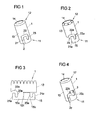
- the FIG. 1 shows a sleeve-shaped gas guide element 1.
- the gas guide 1 is intended to divert gas flowing from a gas generator and in desired way to lead into a gas bag. It can be provided that the gas-conducting element divides the gas flow provided by a gas generator into a plurality of partial flows. This is not mandatory. Likewise, it can be provided that the gas-conducting element discharges the gas flow substantially in one direction.
- the gas guide element has one or more openings for the outflow of gas from the gas guide and / or the connection of the gas guide element with a gas generator is substantially gas-tight or non-gas-tight.
- gas guide elements are described in which gas escapes in a certain way from the gas guide element, it will be apparent to those skilled in the art that in these embodiments the gas exit from the gas guide element can also be realized in another way, without departing from the basic concepts of the present invention Invention, which relate to the attachment of a sleeve-shaped gas guide element to a gas generator to deviate.
- the gas guide element 1 has a first end 11 and a second end 12.
- the first end 11 is intended to be connected to a tube gas generator.
- the second end 12 is provided to direct gas discharged from a gas generator into an airbag.
- gas-conducting element 1 is tubular, for which purpose it has a cylindrical peripheral wall 13 provided with an inner bore 14.
- a slot-shaped recess 2 is realized in the gas guide element 1, which forms a joining channel of a bayonet closure. It is designed to form a bayonet closure together with a stud of a gas generator and accordingly has a width which allows to introduce such a stud into the recess 2.
- the recess 2 has a first region 21 extending axially with respect to the longitudinal axis of the gas-conducting element 1, a region 22 extending in the transverse direction (ie in the circumferential direction) and a region 23 which extends back axially.
- the in the FIG. 1 shown shape of the slot-shaped recess 2 for the realization of the bayonet closure is to be understood only as an example.
- the length and shape of the last region 23 can also be embodied in a different way. It is also possible to dispense entirely with the region 23, in particular when the stud bolt is additionally secured in the recess 2 of the gas-conducting element by means of a latching mechanism.
- the gas guide element 1 may for example consist of plastic or metal. It can be designed as a drawn or rolled part.
- the opening shown at the second end 12 may also be formed in a different form than shown, for example, slot-like manner in the peripheral wall 13 extend. Further, embodiments may be provided in which the second end 12 is formed closed.
- the shape of the gas guide element is variable. For example, this may be formed instead of cylindrical oval or conical, especially when the areas of the gas guide, which participate in the realization of a bayonet closure, are formed on a protruding tab, as for example in the FIG. 2 is shown.
- the gas guide 1 may be formed as an elongated Gasleitrohr with a plurality of lateral gas outlet openings.
- FIGS. 2 and 3 show an alternative embodiment of a gas guide element 1, wherein the FIG. 3 represents the unrolled state of the gas-conducting element 1.
- the gas-conducting element 1 is likewise designed in the shape of a cylinder with a first end 11, a second end 12, a peripheral wall 13 and an inner bore 14.
- the first end 11 is formed by an axially projecting tab 15 of the peripheral wall 13, which is a frontally axially projecting part of the gas guide element 1.
- the tab 15 is formed integrally with the peripheral wall 13. It has two with respect to an axis 151 axisymmetric parts 15a, 15b, which are folded on each other, whereby a reinforced flap 15 is formed with double the material thickness.
- the reinforcement can take place inwards or outwards, ie the segment 15a can come to rest under the segment 15b or on the segment 15b. In both cases, an amplification of the area provided for the bayonet closure is provided, so that axial forces occurring in the triggering case can be safely absorbed even with a small material thickness of the gas-conducting element 1.
- the slot-shaped recess 2a for receiving a stud of a gas generator is designed such that the first axial portion 21a is defined by the lateral edge of the tab 15 extending transversely Region 22a substantially by a recess in the peripheral wall 13 and the turn axially extending portion 23a are realized by recesses in the two axially symmetrical flap parts 15a, 15b, so that this last region 23a, in which the stud of the gas generator is positioned in the assembled state , reinforced is formed.
- the axial plugging motion between the gas guide element 1 and studs is not carried out in guided form, since the first axial portion 21 a only a lateral stop and not limited on both sides recess.
- FIGS. 23 to 25B show a further embodiment of a gas guide element 1, which is similar to the embodiment of the FIGS. 2 and 3 is trained.
- the FIG. 23 shows the unrolled state of the gas-conducting element 1, showing a material blank 20.
- the gas guide element 1 is in turn cylindrically shaped and has a first end 11, a second end 12, a peripheral wall 13 and an inner bore 14.
- the first end 11 is formed by a protruding part 15, which according to the FIG. 23 is formed by folding a portion 15a cut out in the flat-out material blank 20 onto a partial area 15b of the material blank 20 designed to be substantially symmetrical therewith.
- the cut-out portion 15a is connected to the material blank 20 only via a folding axis 151 running in the axial direction.
- a transverse region 22b is formed both in the subregion 15a and in the subregion 15b, the regions 22b coming over the subregion 15b after flaps of the subregion 15a and forming a joining channel 2b.
- the partial regions 15a and 15b are largely axially symmetrical with respect to the folding axis 151.
- a certain deviation from a complete axial symmetry is given, on the one hand, in that a bendable tab 30 is formed in the partial area 15a at its end lying in the circumferential direction, which protrudes into the joining channel 2b and the transverse region 22b.
- a further deviation from a complete axial symmetry is that the portion 15b of the material blank 20 has a nose-like elevation 26b at the beginning of the transverse region 22b. This is optional and can serve to more securely insert a stud into the joining channel 2b.
- a reinforced protruding part 15 with a double material thickness is present.
- the reinforcement can be inward or outward, d. H. the subarea or the segment 15a can come to rest under the subarea or segment 15b or on the subarea or segment 15b, depending on the folding direction. In both cases, an amplification of the area provided for the bayonet closure is provided, so that axial forces occurring in the triggering case can be reliably absorbed even with a small material thickness of the gas guiding element.
- the joining channel 2b widens toward one end. In the illustrated embodiment, this is done in that the end 24b is formed substantially circular. However, widening can also take place in other ways, for example by gradually increasing the width of the transverse region 22b. An advantage associated with a widening is that in the connected state of the bayonet closure there is still a certain play between the gas guide element 1 and the stud bolt or the gas generator. However, widening of the joining channel 2b is optional.
- a plurality of teeth 121 are provided, which are bent in upon production of the gas-conducting element 1.
- the first end 11 of the gas guide element 1, and there the projecting part 15, forms the exclusively substantially transverse joining channel 2b.
- the lateral edge 21 b of the protruding part 15 forms a stop in the circumferential direction. It can be provided that a stud to be inserted into the joining channel 2b is guided in the axial direction on this stop 21b until it passes into the joining channel 2b.
- an axial plugging movement of the gas guide element 1 with respect to a stud to be inserted into the joining channel 2b can also be completely out of alignment Form done without the stay bolt is guided along the lateral edge 21b, but instead is moved in the axial direction at a distance to this.
- the stud reaches the end of the sleeve-shaped peripheral wall 13 when executing the axial plug movement at some point in abutment against the front end 16, see FIG. Fig. 24B , Subsequently, a rotational movement takes place in the circumferential direction, wherein the stud bolt is inserted into the joining channel 2b of the protruding part 15.
- FIGS. 25A and 25B show the airbag element of Figures 24A, 24B in two different perspective views.
- the gas-conducting element has a local injection-in 130, which represents a punctiform constriction of the inner bore 14 of the gas-conducting element 1.
- a local injection 130 acts as a tilt protection during the outflow of the gas.
- a plurality of such local Einpressungen 130 may be provided.
- anti-tippers are also in the FIGS. 20 to 22 to which reference is additionally made.
- FIG. 25B shows the in terms of the FIG. 23 explained Lasche 30.
- the tab 30 is bent outwards, so that the joining channel 2b is released for receiving a stud. After inserting a stud into the joining channel 2b, the tab 30 is bent back again, whereby the stud is secured in the joining channel 2b and prevents the gas guide 1 can work down from the bolt.
- the joining channel 2 b may have a different shape and / or be formed elsewhere in the protruding part 15.
- a locking of a stud in the joining channel can also be done in a different way than via the flexible flap 30.
- the joining channel can have a bottleneck and / or a spring element can protrude into the joining channel. Locking can also be done via tightening torques.
- the design of the gas-conducting element 1 is not bound to a cylindrical shape. This may alternatively be formed, for example, oval or keglig.
- the gas guide may be formed with or without an end opening.
- the gas guide element 1 consists for example of sheet metal.
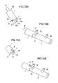
- FIG. 4 shows a further embodiment of a gas guide element 1, which is connectable by means of a bayonet closure with a stud of a gas generator.
- the embodiment of FIG. 4 is largely according to the embodiment of FIG. 1 formed and differs from the latter on the one hand, characterized in that the second axial portion 23c of the slot-shaped recess 2c is formed shorter. On the other hand, there is a difference in that in the embodiment of FIG.
- a locking element is provided which is formed by a tab 3, which projects in the unassembled state obliquely into the interior of the gas guide 1 and adjacent to the slot-shaped recess 2c such that they at the end of the transverse region 22c, and at the Side facing away from the first end 11 defines the boundary of the transverse region 22c.
- FIG. 5 shows a gas guide element according to the FIG. 4 after mounting on a gas generator 4.
- the gas generator 4 is designed as a tubular gas generator and accordingly has a substantially cylindrical shape.
- two stud bolts 41, 42 are welded firmly.
- the studs 41, 42 are used to attach the gas generator 4 to a vehicle structure such as the frame of a vehicle seat or the vehicle chassis or the attachment of the gas generator 4 to a support member which is connected to such a vehicle structure. They have in all the illustrated embodiments preferably a screw, so that the bayonet lock can be additionally secured by a nut screwed.
- the gas guide 1 in the FIG. 5 at its end facing away from the gas generator 4 - unlike in the FIG. 4 shown - is designed as Gasleitrohr with a plurality of laterally formed in the peripheral wall 13 gas outlet openings 16.
- the area of Gas guide 1, which serves to connect to the gas generator 4, however, is according to the FIG. 4 educated.
- the bayonet lock is additionally secured by a nut 6, which is mounted on the threaded bolt 41, as in the FIG. 6 is shown schematically. In this case, the locking tab 3 turns straight when the nut 6 is tightened. As a result, the gas guide element 1 is additionally fixed to the threaded bolt 41.
- the gas-conducting element 1 is designed as a gas-conducting tube
- the gas-conducting tube 1 takes over 100% of the gas distribution.
- the Gasleitrohr 1 thus sits tightly on the gas generator 4 and exiting gas flows only in the pipe.
- Such Gasleitrohr can be used for example in door-integrated gas bag modules for head protection or for head and thorax protection.
- tubular gas generator 4 forms a gas outlet stub 45, on which gas outflow openings 46 are formed in a radial and thrust-neutral manner.
- the gas flow flowing out of the gas outlet openings 46 in the radial direction is diverted through the gas-conducting element 1 and directed into a gas bag (not shown).
- the gas outlet pipe 45 protrudes into the gas-conducting element 1.
- the gas-tightness of the connection between the gas guide 1 and the gas generator 4 adapted to the requirements.
- a complete gas-tightness or alternatively a defined partial gas flow which flows out of the gas-conducting element 1 in the connection region with the gas generator 4 can be provided.
- FIGS. 7A, 7B is as in the embodiment of FIG. 2 formed on the gas guide 1 a tab 15 which has two mirror-symmetrical tab portions 15a, 15b.
- the axis of symmetry and folding edge 152 does not extend in the circumferential direction, but obliquely. In principle, any angle can be realized.
- the two mirror-symmetrical flap parts 15a, 15b are hinged about an axially extending symmetry axis and folding edge 153.
- the FIG. 8B shows the folded state and the reinforcement formed by the superimposed flap portions 15a, 15b.
- the folded parts 15a, 15b can be additionally connected to each other by point connections 155.
- Such point connections 155 may be provided, for example, by spot welding. They allow a greater power transmission in the area of the stud with a small area and minimum material thickness of the gas guide.
- FIG. 9A a variant is shown, in which a flap 15 'of the gas guiding element, which is provided to provide a joining channel 2 of a bayonet closure, an identically shaped flap portion 15 "is placed as material Doppler and suitably fixed FIG. 9B represented, for example, again via point connections 155, which are made for example by welding.
- the result is a reinforced flap 15.
- FIGS. 10A to 13 Embodiments of a gas guide are described, which is not connected by means of a bayonet closure with a gas generator, but by sliding on a gas generator and additional fixing.
- a gas guide element 1 is provided which is tubular between a first end 11 and a second end 12 is and has a provided with an inner bore 14 peripheral wall 13.
- a Vorfix istselement 7 is arranged frontally, which serves for the connection and pre-fixing of the gas guide element 1 to a stud of the gas generator.
- the Vorfix istselement 7 has two substantially axially extending, parallel latching arms 71, 72 which form an elongated recess 73 between them.
- the front ends of the latching arms 71, 72 in this case have inwardly projecting projections 710, 720, which narrow the recess 73 in this area.
- a catching lug 8 likewise projecting from the front side, is provided, which is intended to be suspended in a module carrier or in an airbag and thereby additionally fix the gas-conducting element 1 axially in relation to the gas generator 4.
- FIG. 10B shows the gas guide the Figure 10A in mounted on a tube gas generator 4 with studs 41, 42 state.
- the connection is formed by axially pushing the gas guide element 1 on the gas generator 4, wherein the stud bolt 41 is inserted into the recess 73.
- the latching arms 71, 72 of the Vorfixtechniksijns 7 thereby encompass the one stud bolt 41 of the gas generator 4 and thus provide a prefixing and locking the gas guide element 1 on the gas generator 4 ready.
- This prefixing is in one embodiment by means of a nut corresponding to the nut 6 of FIG. 6 additionally secured.
- the gas guide is additionally fixed by means of the Einhticianlasche 8 by hanging on a module carrier or gas bag.
- FIG. 12 schematically illustrates the gas-conducting element 1, the latching arms 71, 72, the gas generator 4 and the stud bolts 41, 42.
- the Ein vonsche 8 passes through an opening 91 of a fixed or flexible structure 9, which for example, a module carrier of a gas bag module, of which the gas generator 4 and the gas guide 1 form a part, or a fastening element of a gas generator is.
- the suspension lug 8 is passed through the opening 91 of the module carrier 9.
- the Ein vonsche 8 performed by the gas bag in total or in one or more gas bag layers of the Gas bags can be introduced.
- the suspension lug 8 is preferably suspended in a region of the gas bag which remains locally unchanged during inflation of the gas bag.
- FIGS 11A and 11B show an alternative embodiment of a gas-conducting element, which on the one hand has a Vorfix michselement 7 and on the other hand a Ein mentallasche 8.
- the Ein rehabilitationlasche 8 is the Ein rehabilitationlasche 8 as well as the Vorfix michselement 7 formed at the first end 11 of the gas guide element 1 and formed by folding back a frontally projecting tab. This results in the same time, the elongated recess 73 between the latching arms 71, 72nd
- the corresponding suspension is in the FIG. 13 exemplified and shown schematically. It's like in the FIG. 12 schematically the gas guide 1, the latching arms 71, 72, the gas generator 4 and the studs 41, 42 shown.
- the arranged at the first end 11 of the gas guide 1 and folded back hanger tab 8 is passed through an opening 91 of a fixed or flexible structure 9 and thereby secures the gas guide 1 in the axial direction.
- the structure 9 may be, for example, a module carrier of a gas bag module or a fastening element of a gas generator or an airbag, in the latter case the suspension strap being able to be carried through the airbag as a whole or inserted into one or more airbag layers.
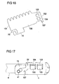
- FIGS. 14 to 17 show a further embodiment of a sleeve-shaped gas guide element 1, which is connectable by means of a bayonet closure with a stud of a gas generator.
- the sleeve-shaped gas guide element 1 is characterized by a in the FIG. 16 formed, for example, produced by punching metal blank 100 formed, which is rolled up to form the gas guide 1. It is provided that the two extending in the axial direction longitudinal edges 101, 102 of the blank are not firmly connected to each other, but overlap each other and thereby how a coil spring can move relative to each other.
- the overlapping area of the two longitudinal edges 101, 102 is, for example, 40 ° to 60 °.
- the blank 100 further includes a tab 15 similar to the flap 15 of FIG. 2 on, in which a slot-shaped recess 2d is designed for the realization of a joining channel of a bayonet closure.
- the blank 100 adjacent to the longitudinal edge 102 forms a latching nose 107.
- this locking lug 107 is due to the spring-like configuration of the gas guide element in the circumferential direction according to the arrow A movable. It protrudes into the joining channel 2d.
- the nose 107 can spring back upon insertion of the stud 41, so that the stud bolt 41 can be brought to its intended end position. Subsequently, the nose 107 springs back, so that the stud bolt 41 is locked. Because the latch 107 can not or only very little spring back in the opposite direction, since such a movement is blocked by the projections 105, 106.
- FIG. 17 shows in perspective from above the connected to the gas generator 4 by means of a bayonet closure gas guide element 1, which secures the stud 41 in the joining channel 2d by the latch 107.
- the Figure 18A shows a sectional view of the gas guide 1 of the FIG. 14 wherein the cut takes place in a region in which the one punch-out 104 and the corresponding projection 106 are realized. It can be seen that the protrusion 106, which protrudes in the manner of a tab, is set outwards and accordingly projects outwards. The same applies to the projection 105 and the punching 103rd
- FIG. 18B shows an alternative embodiment, which basically according to FIGS. 14 to 17 is formed, in which the overlapping portion, however, is directed inwards.
- the cutout 104 is located in the inner arch.
- the tab-like projection 106 which engages through the punch 104, is from the outer arc in the guided inside bow. So he protrudes through the punch 104 inside. The same applies to the projection 105 and the punching 103rd
- an advantage of this embodiment is that due to their inside arrangement, a deploying gas bag can not be damaged by the projections 105, 106.
- the projections 105, 106 may be sized so that when flowing gas from the gas generator 4 in the gas guide 1 and an associated force on the formed by the projections 105, 106 and recesses 103, 104 form-fitting connections to at least one Partial erecting of the projections 105, 106 may lead, so erected inwardly projecting projections 105, 106 are then supported on a disposed within the gas guide 1 gas generator 4, so that an improved support on the gas generator 4 is realized.
- FIG. 19 shows a variant in which in the region of the joining channel 2, which serves to guide the stud bolt 41 of the gas generator 4, a resilient tongue 108 is formed with, in order to lock the stud bolt 41 in its final position.
- the resilient tongue 108 is formed adjacent to the end position of the stud bolt 41 in the joining channel 2. It is punched, for example, from the surrounding material and shaped accordingly.
- the stud bolt 41 can be joined in a simple manner with normal manual force. However, the reverse path is blocked by the spring-biased tongue 108.
- FIG. 19 is the resilient tongue 108 on a tab 15 (corresponding to the tab 15 of FIG. 2 or the tab 15 of the FIGS. 13 to 17 ) are formed. It blocks the stay bolt of the gas generator after it has been brought into its final position in the joining channel 2.
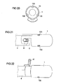
- FIGS. 20 to 22 relate to embodiments in which a sleeve-shaped gas guide element 1 is connected by means of bayonet closure with a tube gas generator 4.
- one or more local impressions 130 are introduced into the peripheral wall 13 of the gas guide element 1, which protrude into the interior of the sleeve 1.
- the local impressions 130 are thereby introduced into the sleeve-shaped gas guide element 1 before it is placed on the gas generator 4.
- At the gas generator 4 is no provided the local Inpresseptept 130 corresponding counter profile; Rather, its lateral surface is cylindrical in the usual way.
- the local indentations 130 represent punctual constrictions. They serve for additional fixing of the gas-conducting element 1 on the gas generator 4 and act as anti-tilting device during the outflow process of the gas. A tilting of the gas guide element 1 relative to the gas generator 4 is thus prevented.
- the end of the gas-conducting element 1, which is connected to the gas generator 4 is not gas-tight, since gas can flow past the local indentations 130 laterally.
- the other end of the gas guide element 1 may be open or closed.
- FIG. 21 shows the gas guide the FIG. 20 mounted on a gas generator 4.
- two of three local indentations 130 can be seen, which act as anti-tilt device.
- the number of local indentations 130 may vary. In the embodiment of FIG. 22 only a single local injection 130 is provided. This is opposite, ie offset by 180 ° to the stud 41 formed in the gas guide 1. This also achieves a tilt protection.
- the gas guide element 1 instead of puncture constrictions on linear constrictions, which can be axial, radial and / or oblique.
- One or more of such line-shaped constrictions may be provided.
- a gas tightness could also be provided at the end of the gas guide element 1 connected to the gas generator.
- the gas guide element according to the invention is used in one embodiment in a side airbag module, in particular in a side airbag module with a two-chamber side airbag, wherein the gas guide is designed such that it is deflected from the gas generator gas flowing in two directions.
Landscapes
- Engineering & Computer Science (AREA)
- Mechanical Engineering (AREA)
- Physics & Mathematics (AREA)
- Fluid Mechanics (AREA)
- Air Bags (AREA)
- Feeding, Discharge, Calcimining, Fusing, And Gas-Generation Devices (AREA)
- General Engineering & Computer Science (AREA)
Description
Die Erfindung betrifft Vorrichtungen für Personen-Schutzsysteme eines Fahrzeugs gemäß den Oberbegriffen der Patentansprüche 1, 7 und 10.The invention relates to devices for personal protection systems of a vehicle according to the preambles of
Bei als Fahrzeuginsassen-Rückhaltesystemen eingesetzten Gassackvorrichtungen besteht allgemein das Erfordernis, das in axialer und/oder radialer Richtung aus einem Gasgenerator ausströmende Gas in ein oder mehrere bestimmte Richtungen umzuleiten, damit das Gas einen Gassack gleichmäßig und in definierter Weise befüllen kann. Weiter ist allgemein anzustreben, dass der Gassack angrenzend an die Ausströmöffnungen eines Gasgenerators durch die ausströmenden Gase nicht beschädigt wird.In gas bag devices used as vehicle occupant restraint systems, there is generally the requirement to divert the gas flowing out of a gas generator in the axial and / or radial direction into one or more specific directions, so that the gas can fill a gas bag uniformly and in a defined manner. Furthermore, it is generally desirable to ensure that the gas bag adjacent to the outflow openings of a gas generator is not damaged by the outflowing gases.
Zur Lösung dieser Probleme ist es bekannt, das aus einem Gasgenerator ausströmende Gas unter Verwendung eines als Massenstromverteiler wirkenden Gasleitelements in einen Gassack einzuleiten. Dabei ist es bekannt, ein solches Gasleitelement als Füllrohr aus Metall, als Füllschlauch aus unterschiedlichsten Geweben, als Gewebediffusor oder als starren Diffusor auszubilden.To solve these problems, it is known to introduce the effluent gas from a gas generator using an acting as a mass flow distributor gas guide into a gas bag. It is known to form such a gas guide as a filling tube made of metal, as a filling tube made of different tissues, as a fabric diffuser or as a rigid diffuser.
Zur Befestigung eines Gasleitelements an einem mit Stehbolzen versehenen Gasgenerator wurde vorgeschlagen, am Gasleitelement oder einem mit diesem verbundenen Teil eine kreisförmige Öffnung auszubilden, in die ein Stehbolzen des Gasgenerators eingesetzt wird. Solche Lösungen sind in der
Aus der Druckschrift
Die
Der vorliegenden Erfindung liegt die Aufgabe zugrunde, eine weitere Vorrichtung für ein Personen-Schutzsystem eines Fahrzeugs zur Verfügung zu stellen, die eine Befestigung eines Gasleitelements an einem mit Stehbolzen versehenen Gasgenerator ermöglicht.The present invention has for its object to provide a further device for a personal protection system of a vehicle is available, which allows attachment of a gas guide element to a bolt provided with gas generator.
Diese Aufgabe wird erfindungsgemäß durch eine Vorrichtung mit den Merkmalen des Anspruchs 1, eine Vorrichtung mit den Merkmalen des Anspruchs 7 und eine Vorrichtung mit den Merkmalen des Anspruchs 10 gelöst. Ausgestaltungen der Erfindung sind in den Unteransprüchen angegeben.This object is achieved by a device having the features of
Danach sieht eine erste Ausgestaltung der Erfindung vor, dass das Gasleitelement mittels eines Bajonett-Verschlusses mit mindestens einem der Stehbolzen des Gasgenerators verbunden ist. Unter einem Bajonett-Verschluss wird dabei jede Art von Verschluss verstanden, bei der eine Verbindung des Gasleitelements mit dem Stehbolzen bzw. dem Gasgenerator zumindest eine axiale Steckbewegung und eine zu dieser im Wesentlichen quer, d.h. in Umfangsrichtung erfolgende Drehbewegung umfasst. Daran können sich weitere Relativbewegungen anschließen, bis der Stehbolzen seine Endposition im Bajonett-Verschluss erreicht hat. Die axiale Steckbewegung kann dabei, muss aber nicht in geführter Form erfolgen.Thereafter, a first embodiment of the invention provides that the gas guide element is connected by means of a bayonet closure with at least one of the stud bolts of the gas generator. In this case, a bayonet closure is understood to be any type of closure in which a connection of the gas-conducting element to the stud or the gas generator has at least one axial plug movement and one transverse thereto, ie. comprises circumferential rotational movement. This can be followed by further relative movements until the stud has reached its end position in the bayonet lock. The axial insertion movement can, but does not have to be in guided form.
Durch Verbinden des Gasleitelementes mit einem Stehbolzen des Gasgenerators mittels eines Bajonett-Verschlusses wird eine schnell zu realisierende Verbindung der beiden Teile ermöglicht. Zur Realisierung eines Bajonett-Verschlusses sind dabei lediglich eine axiale Bewegung und eine Bewegung in Umfangsrichtung erforderlich, nicht dagegen eine Kipp- oder eine Querbewegung, so dass nur ein geringer Platzbedarf bei der Montage besteht.By connecting the gas guide element with a stud of the gas generator by means of a bayonet closure, a connection of the two parts to be realized quickly is made possible. For the realization of a bayonet closure while only an axial movement and a movement in the circumferential direction are required, not a tilting or a transverse movement, so that there is only a small footprint in the assembly.
Gemäß der Erfindung ist weiter vorgesehen, dass das Gasleitelement zur Bildung eines Bajonett-Verschlusses einen Fügekanal für einen Stehbolzen des Gasgenerators ausbildet. Dieser Fügekanal ist beispielsweise derart geformt, dass er einen ersten, im Wesentlichen axial verlaufenden Bereich und einen zweiten, sich an den ersten Bereich anschließenden, im Wesentlichen quer verlaufenden Bereich aufweist. Daran kann sich ein dritter, sich an den zweiten Bereich anschließender und wiederum im Wesentlichen axial verlaufenden Bereich anschließen. Durch den ersten Bereich erfolgt die axiale Steckbewegung in geführter Form. Durch den zusätzlichen dritten Bereich wird eine zusätzliche Sicherung der Verbindung erreicht. So kann, nachdem der Stehbolzen seine Endposition am Ende des dritten Bereichs erreicht hat, die Verbindung nicht durch ledigliches Drehen des Gasleitelements wieder gelöst werden. Insbesondere ein unbeabsichtigtes Lösen der Verbindung durch Rüttelbewegungen wird hierdurch sicher verhindert.According to the invention, it is further provided that the gas-conducting element for forming a bayonet closure forms a joining channel for a stud bolt of the gas generator. By way of example, this joining channel is shaped in such a way that it has a first, essentially axially extending region and a second, essentially transverse region adjoining the first region. This can be followed by a third, adjoining the second region and again in turn substantially axially extending region. Through the first area, the axial insertion movement takes place in guided form. The additional third area provides additional security for the connection. Thus, after the stay bolt has reached its end position at the end of the third area, the connection can not be released again by just turning the gas guide element. In particular a unintentional release of the connection by shaking movements is thereby reliably prevented.
In einer weiteren Ausgestaltung der Erfindung ist vorgesehen, dass der Fügekanal ausschließlich aus einem im Wesentlichen quer zur Längsachse des Gasleitelements verlaufenden Bereich besteht, der an einem axial vorstehenden Teil des Gasleitelements ausgebildet ist. Die axiale Steckbewegung des Gasleitelements in Bezug auf den Stehbolzen, die den einen Bestandteil eines Bajonett-Verschlusses ausmacht, erfolgt dabei nicht in geführter Form, d.h. nicht in einem Kanal oder einer Aussparung. Bei Ausführen der axialen Steckbewegung gerät der Stehbolzen zunächst in Anschlag an das stirnseitige Ende des Gasleitelements. Anschließend erfolgt eine in Umfangsrichtung erfolgende Drehbewegung, die den anderen Bestandteil eines Bajonett-Verschlusses ausmacht, wobei der Stehbolzen in den Fügekanal des vorstehenden Teils einführt wird.In a further embodiment of the invention, it is provided that the joining channel consists exclusively of a region running essentially transversely to the longitudinal axis of the gas-conducting element, which region is formed on an axially protruding part of the gas-conducting element. The axial insertion movement of the gas guide element with respect to the stud, which makes up the one part of a bayonet closure, does not take place in guided form, i. not in a channel or a recess. When executing the axial plug movement of the stud bolt first comes into abutment against the front end of the gas guide. Subsequently, a rotational movement takes place in the circumferential direction, which constitutes the other part of a bayonet closure, wherein the stud is inserted into the joining channel of the projecting part.
Gemäß der Erfindung ist weiter vorgesehen, dass das Gasleitelement Mittel zur Verriegelung des Bajonett-Verschlusses aufweist. Diese können in unterschiedlicher Weise ausgebildet sein. In einer Ausführungsvariante umfassen die Mittel zur Verriegelung des Bajonett-Verschlusses eine federnd am Gasleitelement angeordnete oder ausgebildete Rastnase, die den Stehbolzen nach Erreichen seiner Endposition im Bajonett-Verschluss arretiert. Die Rastnase ragt dabei in den Fügekanal, so dass sie bei Einbringen des Stehbolzens in den Fügekanal ausgelenkt wird.According to the invention it is further provided that the gas guide element has means for locking the bayonet closure. These can be designed in different ways. In one embodiment, the means for locking the bayonet closure comprises a resiliently arranged on the gas guide or trained locking lug which locks the stud after reaching its end position in the bayonet lock. The detent protrudes into the joining channel, so that it is deflected upon insertion of the stud into the joining channel.
Zur Realisierung einer federnden Ausbildung der Rastnase kann beispielsweise vorgesehen sein, dass das Gasleitelement aus einem gerollten Zuschnitt besteht und die Rastnase an dem Zuschnitt angeformt ist. Zwei Längskanten des Zuschnitts überlappen im gerollten Zustand einander, wobei der Grad der Überlappung bei Auftreten einer in Umfangsrichtung auftretenden Kraft variiert. Bei Einführen eines Stehbolzens in den Fügekanal übt dieser eine im Umfangsrichtung wirkende Kraft auf die Rastnase und damit auf den Zuschnitt aus, was zu einer Änderung des Überlappungsgrades der Längskanten führt, wodurch die Rastnase wegfedert. Alternativ kann vorgesehen sein, dass die Rastnase als federnde Zunge im Bereich des Fügekanals ausgebildet ist.To realize a resilient embodiment of the locking lug can be provided, for example, that the gas guide element consists of a rolled blank and the locking lug is formed on the blank. Two longitudinal edges of the blank overlap in a rolled condition, the degree of overlap varying upon the occurrence of a circumferentially occurring force. Upon insertion of a stud into the joining channel this exerts a force acting in the circumferential direction of the latching lug and thus on the blank, resulting in a change in the degree of overlap of the longitudinal edges, whereby the latching spring wegfedert. Alternatively it can be provided that the detent is designed as a resilient tongue in the region of the joining channel.
In einer weiteren Ausführungsvariante umfassen die Mittel zur Verriegelung des Bajonett-Verschlusses eine am Gasleitelement angeordnete Lasche, die im nicht montierten Zustand schräg in das Innere des Gasleitelements ragt und die bei Aufsetzen einer Mutter oder dergleichen auf den Stehbolzen und Anziehen der Mutter sich gerade ausrichtet und dabei das Gasleitelement zusätzlich am Gasgenerator fixiert.In a further embodiment, the means for locking the bayonet closure comprise a flap arranged on the gas guide, which projects in the unassembled state obliquely into the interior of the gas guide element and which aligns when placing a nut or the like on the stud and tightening the nut straight and while the gas guide additionally fixed to the gas generator.
Erfindungsgemäß umfassen die Mittel zur Verriegelung des Bajonett-Verschlusses eine am Gasleitelement angeordnete, biegbare Lasche, mittels derer der Bajonett-Verschluss nach Erreichen der Endposition des Stehbolzens durch Umbiegen der Lasche gesichert werden kann.According to the invention, the means for locking the bayonet closure comprise a bendable lug arranged on the gas-conducting element, by means of which the bayonet closure can be secured after reaching the end position of the stud by bending over the lug.
Die Erfindung sieht weiter vor, dass das Gasleitelement ist in dem Bereich, in dem es den Fügekanal bildet, zumindest teilweise durch eine von der Umfangswand des Gasleitelements axial abstehende Lasche gebildet ist.The invention further provides that the gas guide element is formed in the region in which it forms the joining channel, at least partially by a flap projecting axially from the peripheral wall of the gas guide element.
Weiter weist das Gasleitelement in dem Bereich, in dem es den Fügekanal bildet, gemäß einer Ausführungsvariante der Erfindung zumindest teilweise eine Materialverstärkung auf. Dies ermöglicht es, auch bei geringer Materialstärke des Gasleitelements sicherzustellen, dass bei Einströmen von Gas aus dem Gasgenerator in das Gasleitelement auftretende Kräfte sicher beherrscht werden können.Next, the gas guide element in the region in which it forms the joining channel, according to an embodiment of the invention, at least partially on a material reinforcement. This makes it possible to ensure, even with a low material thickness of the gas-conducting element, that forces occurring when gas flows from the gas generator into the gas-conducting element can be reliably controlled.
Eine Ausführungsvariante dazu sieht vor, dass eine Lasche des Gasleitelements durch Aufeinanderklappen mindestens zweier Laschenteile gebildet oder ein Materialdoppler auf der Lasche angeordnet ist, so dass die Lasche im Vergleich mit der Umfangswand des Gasleitelements eine erhöhte Materialdicke aufweist.An embodiment variant for this provides that a tab of the gas guiding element is formed by folding one another at least two tab parts or a material doubler is arranged on the tab, so that the tab has an increased material thickness in comparison with the peripheral wall of the gas guiding element.
In einer zweiten Ausgestaltung der Erfindung erfolgt eine Verbindung des Gasleitelementes mit dem Gasgenerator in der Weise, dass das Gasleitelement mindestens eine Aussparung aufweist, in die ein Stehbolzen des Gasgenerators bei Aufschieben des Gasleitelements in axialer Richtung auf den Gasgenerator eingeführt wird. Hierdurch wird eine gewisse Fixierung des Gasleitelementes am Stehbolzen des Gasgenerators in dem Sinne erreicht, dass eine Drehbewegung zwischen dem Gasleitelement und dem Gasgenerator verhindert und durch das Ende der Aussparung ein axialer Anschlag bereitgestellt wird.In a second embodiment of the invention, the gas-conducting element is connected to the gas generator in such a way that the gas-conducting element has at least one recess into which a stud bolt of the gas generator is inserted in the axial direction onto the gas generator when the gas-conducting element is slid on. As a result, a certain fixation of the gas-conducting element on the stud of the gas generator is achieved in the sense that a rotational movement between the gas-conducting element and the gas generator is prevented and an axial stop is provided by the end of the recess.
Das Gasleitelement weist erfindungsgemäß des Weiteren mindestens ein Sicherungselement auf, das dazu vorgesehen und ausgebildet ist, in eine weitere Struktur eingehängt zu werden und dadurch das Gasleitelement zusätzlich in axialer Richtung am Gasgenerator zu sichern. Das Einhängen kann beispielsweise in einen Modulträger oder in einen Gassack eines Gassackmoduls erfolgen. Das Sicherungselement dient dazu, bei Einströmen von Gas aus dem Gasgenerator in das Gasleitelement und dabei auftretenden starken axialen Kräften das Gasleitelement zusätzlich axial am Gasgenerator zu sichern.According to the invention, the gas-conducting element furthermore has at least one securing element which is provided and designed to be suspended in a further structure and thereby additionally secure the gas-conducting element in the axial direction on the gas generator. The hanging can be done for example in a module rack or in a gas bag of a gas bag module. The fuse element is used when gas flows from the gas generator in the Gas guide and thereby strong axial forces to secure the gas guide additionally axially on the gas generator.
Ein Einhängen des Sicherungselements in eine weitere Struktur ist dabei dahingehend zu verstehen, dass das Sicherungselement nicht fest mit der weiteren Struktur verbunden wird. Gesonderte Befestigungsmaßnahmen sind somit nicht erforderlich. Beispielsweise ist das Sicherungselement als Lasche ausgebildet, die eine Öse oder Öffnung der Struktur durchragt und dadurch eingehängt ist.An attachment of the securing element in a further structure is to be understood as meaning that the securing element is not firmly connected to the further structure. Separate attachment measures are therefore not required. For example, the securing element is designed as a tab which extends through an eyelet or opening of the structure and is suspended thereby.
Die genannte Aussparung ist beispielsweise länglich ausgebildet und axial ausgerichtet. Ihre Breite ist zumindest so groß wie der Durchmesser des Stehbolzens, so dass dieser ohne Klemmung in der Aussparung angeordnet ist.Said recess is for example elongated and axially aligned. Their width is at least as large as the diameter of the stud, so that it is arranged without clamping in the recess.
In einer Ausgestaltung ist die Aussparung an einem axial von der Umfangswand des Gasleitelements abstehenden Teil ausgebildet. Sie wird beispielsweise zwischen zwei Rastarmen bereitgestellt, die stirnseitig von dem Gasleitelement abstehen.In one embodiment, the recess is formed on an axially projecting from the peripheral wall of the gas guide member. It is provided, for example, between two latching arms, which protrude from the end face of the gas guide element.
Weiter sind in einer Ausführungsvariante Rastmittel vorgesehen, die einen in die Aussparung eingeführten Stehbolzen darin verrasten. Bei Einführen des Stehbolzens in die Aussparung wird dieser also zusätzlich in der Aussparung verrastet, so dass zumindest bei lediglich geringen axialen Kräften auch eine axiale Fixierung von Gasleitelement und Gasgenerator erfolgt. Die Rastmittel werden beispielsweise durch an Rastarmen ausgebildete, nach innen ragende Vorsprünge bereitgestellt, die die Aussparung in diesem Bereich verengen.Next locking means are provided in an alternative embodiment, which lock a introduced into the recess stud bolts therein. Upon insertion of the stud into the recess of this is thus additionally locked in the recess, so that at least with only slight axial forces and axial fixation of the gas guide element and gas generator takes place. The latching means are provided for example by formed on latching arms, inwardly projecting projections which narrow the recess in this area.
Das Sicherungselement ist erfindungsgemäß durch eine Einhängelasche gebildet, wobei das Ende der Einhängelasche in eine Richtung weist, die von dem Gasgenerator weg gerichtet ist. Hierdurch wird ein Einhängen derart ermöglicht, dass eine Sicherung gegen axiale Kräfte gegeben ist, die bei Einströmen von Gas in das Gasleitelement entstehen können und das Gasleitelement vom Gasgenerator wegdrücken. Das Sicherungselement kann dabei auf verschiedenste Weise am Gasleitelement angeordnet sein, sowohl stirnseitig als auch an dessen Umfang. Es kann einstückiger Bestandteil des Gasleitelements oder durch ein gesondertes, am Gasleitelement befestigtes Teil gebildet sein.The securing element according to the invention is formed by a Einhängelasche, wherein the end of the Einhängelasche points in a direction which is directed away from the gas generator. As a result, a suspension is made possible in such a way that a safeguard against axial forces is given, which can occur when gas flows into the gas-conducting element and push away the gas-conducting element from the gas generator. The securing element can be arranged in various ways on the gas guide, both the front side and at the periphery. It may be formed integral part of the gas guide or by a separate, fixed to the gas guide member.
Gemäß einer Ausführungsvariante ist die Aussparung des Gasleitelements in einem Teil ausgebildet ist, das sich ausgehend von seiner Verbindung mit der Umfangswand des Gasleitelements in einer ersten Richtung erstreckt. Des Weiteren erstreckt sich das Sicherungselement ausgehend von seiner Verbindung mit der Umfangswand des Gasleitelements in eine zweite Richtung, wobei die erste Richtung und die zweite Richtung entgegengesetzt sind. Das Sicherungselement und das Fixierungselement erstrecken sich somit in entgegengesetzter Richtung.According to one embodiment, the recess of the gas guide element is formed in a part which, starting from its connection to the peripheral wall of Gas guide element extends in a first direction. Furthermore, the securing element extends from its connection with the peripheral wall of the gas guiding element in a second direction, wherein the first direction and the second direction are opposite. The securing element and the fixing element thus extend in the opposite direction.
In einer dritten Ausgestaltung der Erfindung erfolgt eine Verbindung des Gasleitelementes mit dem Gasgenerator in der Weise, dass das Gasleitelement einen im Wesentlichen quer verlaufenden Fügekanal aufweist, in den mindestens einer der Stehbolzen des Gasgenerators durch eine in Umfangsrichtung erfolgende Drehbewegung einführbar ist, wobei der Fügekanal zumindest teilweise an einem stirnseitig axial vorstehenden Teil des Gasleitelements ausgebildet ist. Dabei liegt der Anfang des Fügekanals an einer seitlichen Kante des vorstehenden Teils. Durch diese Erfindungsvariante wird eine einfache Ausgestaltung bereitgestellt, da der Fügekanal nur in einer Richtung im Material des Gasleitelements ausgebildet werden braucht.In a third embodiment of the invention, the gas-conducting element is connected to the gas generator in such a way that the gas-conducting element has a substantially transverse joining channel, into which at least one of the stud bolts of the gas generator can be introduced by a rotational movement in the circumferential direction, the joining channel at least Partially formed on a front side axially projecting part of the gas guide. In this case, the beginning of the joining channel is located at a lateral edge of the projecting part. This variant of the invention provides a simple configuration, since the joining channel only needs to be formed in one direction in the material of the gas-conducting element.
Dass der Fügekanal im Wesentlichen quer verläuft ist dahingehend zu verstehen, dass er stärker in Querrichtung verläuft als in axialer Richtung, was natürlich auch einschließt, dass er näherungsweise exakt in Querrichtung verläuft. Der Fügekanal kann dabei gerade oder gebogen ausgebildet sein.The fact that the joining channel runs essentially transversely is to be understood to mean that it runs more in the transverse direction than in the axial direction, which of course also implies that it runs approximately exactly in the transverse direction. The joining channel can be formed straight or curved.
Erfindungsgemäß weist das vorstehende Teil eine biegbare oder flexible Lasche auf, mittels derer der Fügekanal nach Einführen des Stehbolzens in den Fügekanal verschließbar ist. Beispielsweise wird die Lasche erst aufgebogen, um den Fügekanal freizugeben, und wird sie nach Einführen des Stehbolzens in den Fügekanal zurückgebogen, um den Fügekanal wieder zu verschließen und den Stehbolzen in dem Fügekanal gegen ein Lösen zu sichern.According to the invention, the protruding part has a bendable or flexible tab, by means of which the joining channel can be closed after insertion of the stud into the joining channel. For example, the tab is first bent up to release the joining channel, and it is bent back after insertion of the stud into the joining channel to re-close the joining channel and to secure the stud in the joining channel against loosening.
In einer weiteren Ausführungsvariante ist das vorstehende Teil gebildet durch Klappen eines im flach ausgebreiteten Materialzuschnitt des Gasleitelements ausgeschnittenen Teilbereichs, der nur über eine in axialer Richtung verlaufende Klappachse mit dem Materialzuschnitt verbunden ist, auf einen dazu im Wesentlichen symmetrisch ausgebildeten Teilbereich des Materialzuschnitts. Dabei sind in beiden Teilbereichen quer verlaufende Bereiche des Fügekanals ausgebildet, die nach Klappen des einen Teilbereichs auf den anderen Teilbereich übereinander zu liegen kommen.In a further embodiment variant, the projecting part is formed by folding a section cut out in the flatly spread material blank of the gas guide element, which is connected to the material blank only via a folding axis running in the axial direction, onto a part region of the material blank that is substantially symmetrical therefor. In this case, transversely extending regions of the joining channel are formed in both sub-regions, which come to lie one above the other on the other sub-region after flaps of one sub-region.
Es kann vorgesehen sein, dass der im Wesentlichen quer verlaufende Fügekanal sich zu seinem Ende hin aufweitet, beispielsweise durch Bildung eines näherungsweise kreisförmigen Bereichs. Dies kann mit dem Vorteil eines gewissen Spiels zwischen dem Gasleitelement und dem Gasgenerator im verriegelten Zustand verbunden sein.It can be provided that the substantially transverse joining channel widens towards its end, for example by forming an approximately circular region. This can be associated with the advantage of a certain clearance between the gas guiding element and the gas generator in the locked state.
Ein weiteres Ausführungsbeispiel der Erfindung sieht vor, dass in der Umfangswand des Gasleitelements mindestens eine punktuelle oder linienförmige Verengung ausgebildet ist, die eine Kippsicherung des Gasleitelements gegenüber dem Gasgenerator bereitstellt.A further exemplary embodiment of the invention provides that at least one punctiform or linear constriction is formed in the circumferential wall of the gas guide element, which provides a tilt protection of the gas guide element with respect to the gas generator.
Die Erfindung wird nachfolgend unter Bezugnahme auf die Figuren der Zeichnung anhand mehrerer Ausführungsbeispiele näher erläutert. Es zeigen:
- Fig. 1
- ein erstes Ausführungsbeispiel eines hülsenförmigen Gasleitelements, dessen eines Ende dazu ausgebildet ist, mittels eines Bajonett-Verschlusses mit einem Stehbolzen eines Gasgenerators verbunden zu werden;
- Fig. 2
- ein zweites Ausführungsbeispiel eines hülsenförmigen Gasleitelements, dessen eines Ende dazu ausgebildet ist, mittels eines Bajonett-Verschlusses mit einem Stehbolzen eines Gasgenerators verbunden zu werden, wobei der Teil des Gasleitelementes, der mit dem Stehbolzen des Gasgenerators zusammenwirkt, verstärkt ausgebildet ist;
- Fig. 3
- das abgerollte Gasleitelement der
Figur 2 ; - Fig. 4
- ein drittes Ausführungsbeispiel eines hülsenförmigen Gasleitelements, dessen eines Ende dazu ausgebildet ist, mittels eines Bajonett-Verschlusses mit einem Stehbolzen eines Gasgenerators verbunden zu werden, wobei das Gasleitelement zusätzlich ein Verriegelungselement aufweist;
- Fig. 5
- eine schematische Darstellung eines per Bajonett-Verschluss mit einem Gasgenerator verbundenen Gasleitelements, wobei das Gasleitelement als Gasleitrohr ausgebildet ist;
- Fig. 6
- eine Schnittdarstellung der Anordnung der
Figur 5 unter Darstellung einer zusätzlichen Verriegelung des Gasleitelements mit dem Gasgenerator; - Fig. 7A, 7B
- eine erste Ausführungsvariante einer Lasche eines Gasleitelements, die mittels eines Bajonett-Verschlusses mit einem Stehbolzen eines Gasgenerators verbindbar ist, wobei die
Figur 7A zwei aufgeklappte Laschenteile und dieFigur 7B die zusammengeklappten Laschenteile des fertigen Gasleitelements zeigt; - Fig. 8A, 8B, 8C
- eine zweite Ausführungsvariante einer Lasche eines Gasleitelements, die mittels eines Bajonett-Verschlusses mit einem Stehbolzen eines Gasgenerators verbindbar ist, wobei die
Figur 8A zwei aufgeklappte Laschenteile, dieFigur 8B die zusammengeklappten Laschenteile des fertigen Gasleitelements und dieFigur 8C eine punktierte Verbindung durch Schweißen oder dergleichen der beiden Laschenteile zeigt; - Fig. 9A, 9B
- eine dritte Ausführungsvariante einer Lasche eines Gasleitelements, die mittels eines Bajonett-Verschlusses mit einem Stehbolzen eines Gasgenerators verbindbar ist, wobei die
Figur 9A ein Laschenteil und einen Materialdoppler und dieFigur 9B eine punktierte Verbindung durch Schweißen oder dergleichen der beiden Teile zeigt; - Fig. 10A
- ein weiteres Ausführungsbeispiel eines Gasleitelements, wobei das Gasleitelement ein Vorfixierungselement für eine Vorfixierung an einem Gasgenerator und eine Einhängelasche ausbildet;
- Fig. 10B
- das Gasleitelement der
Figur 10A im montierten Zustand an einem Gasgenerator; - Fig. 11A
- ein weiteres Ausführungsbeispiel eines Gasleitelements, das ein Vorfixierungselement für eine Vorfixierung an einem Gasgenerator und eine Einhängelasche ausbildet;
- Fig. 11B
- das Gasleitelement der
Figur 11A in montiertem Zustand an einem Gasgenerator; - Fig. 12
- eine Anordnung gemäß der
Figur 10B , wobei die Einhängelasche des Gasleitelements durch einen Gassack durchgeführt oder in ein oder mehrere Gassacklagen eingeführt oder in ein Befestigungselement eingehängt ist; - Fig. 13
- eine Anordnung gemäß der
Figur 11B , wobei die Einhängelasche des Gasleitelements durch einen Gassack durchgeführt oder in ein oder mehrere Gassacklagen eingeführt oder in ein Befestigungselement eingehängt ist; - Fig. 14
- ein weiteres Ausführungsbeispiel eines Gasleitelementes, dessen eines Ende derart ausgebildet ist, dass es mittels eines Bajonett-Verschlusses mit einem Stehbolzen eines Gasgenerators verbindbar ist, wobei das Gasleitelement ein Federelement zur Arretierung eines solchen Stehbolzens aufweist;
- Fig. 15
- das
Gasleitelement der Figur 14 , wobei der Federmechanismus für das Federelement dargestellt ist; - Fig. 16
- das aufgerollte Gasleitelement der
Figuren 14 ;und 15 - Fig. 17
- das mit einem Gasgenerator verbundene Gasleitelement der
Figuren 14 ;und 15 - Fig. 18A
- eine Schnittdarstellung des Gasleitelements der
Figur 14 , wobei der überlappende Zuschnitt außen anliegt; - Fig. 18B
- eine Schnittdarstellung eines alternativen Gasleitelements, bei dem der überlappende Zuschnitt nach innen geleitet ist;
- Fig. 19
- ein weiteres Ausführungsbeispiel eines Gasleitelementes, das in dem Bereich, der den Teil eines Bajonett-Verschlusses ausbildet, eine Rastnase ausbildet;
- Fig. 20
- eine Ansicht von vorne auf ein Gasleitelement, das dazu ausgebildet ist, mittels eines Bajonett-Verschlusses mit einem Gasgenerator verbunden zu werden, wobei das Gasleitelement mehrere lokale Einpressungen zur zusätzlichen Fixierung des Gasleitelementes in Bezug auf den Gasgenerator aufweist;
- Fig. 21
- in Ansicht von oben das mit einem Gasgenerators mittels eines Bajonett-Verschlusses verbundene Gasleitelement der
Figur 20 , wobei zwei lokale Einpressungen zu sehen sind; - Fig. 22
- ein alternatives Ausführungsbeispiel der Verbindung eines Gasleitelementes mit einem Gasgenerator mittels eines Bajonettverschlusses, wobei lediglich eine lokale Einpressung gegenüberliegend einem Stehbolzen zur zusätzlichen Fixierung des Gasleitelements am Gasgenerator vorgesehen ist;
- Fig. 23
- ein weiteres Ausführungsbeispiel eines hülsenförmigen Gasleitelementes, das im abgerollten Zustand als Materialzuschnitt dargestellt ist;
- Fig. 24A
- das hülsenförmige Gasleitelement, das durch den
Zuschnitt der Figur 23 hergestellt ist, in einer ersten seitlichen Ansicht; - Fig. 24B
- das hülsenförmige Gasleitelement, das durch den
Zuschnitt der Figur 23 hergestellt ist, in einer zweiten seitlichen Ansicht; - Fig. 25A
- das Gasleitelement der
Figuren 24A, 24B in einer ersten perspektivischen Darstellung, wobei eine lokale Einpressung des Gasleitelementes erkennbar ist; und - Fig. 25B
- das Gasleitelement der
Figur 25A in einer anderen perspektivischen Darstellung, in der eine abgewinkelte Befestigungslasche des Gasleitelementes erkennbar ist.
- Fig. 1
- a first embodiment of a sleeve-shaped gas guide, one end of which is adapted to be connected by means of a bayonet closure with a stud of a gas generator;
- Fig. 2
- a second embodiment of a sleeve-shaped gas guide element, whose one end is adapted to be connected by means of a bayonet closure with a stud of a gas generator, wherein the part of the gas conducting element, which cooperates with the stud of the gas generator, is reinforced formed;
- Fig. 3
- the unrolled gas guide the
FIG. 2 ; - Fig. 4
- a third embodiment of a sleeve-shaped gas guide element, whose one end is adapted to be connected by means of a bayonet closure with a stud of a gas generator, wherein the gas guide element additionally comprises a locking element;
- Fig. 5
- a schematic representation of a connected by bayonet closure with a gas generator gas conducting element, wherein the gas-conducting element is designed as Gasleitrohr;
- Fig. 6
- a sectional view of the arrangement of
FIG. 5 showing an additional locking of the gas guiding element with the gas generator; - Fig. 7A, 7B
- a first embodiment of a tab of a gas guide element, which is connectable by means of a bayonet closure with a stud of a gas generator, wherein the
FIG. 7A two unfolded flap parts and theFIG. 7B shows the folded flap parts of the finished gas guide element; - 8A, 8B, 8C
- a second embodiment of a tab of a gas guide element, which is connectable by means of a bayonet closure with a stud of a gas generator, wherein the
Figure 8A two unfolded flap parts, theFIG. 8B the folded flap parts of the finished gas guide element and theFIG. 8C shows a dotted connection by welding or the like of the two flap parts; - Figs. 9A, 9B
- a third embodiment of a tab of a gas guide element, which is connectable by means of a bayonet closure with a stud of a gas generator, wherein the
Figure 9A a flap part and a material Doppler and theFIG. 9B shows a dotted connection by welding or the like of the two parts; - Fig. 10A
- a further embodiment of a gas-conducting element, wherein the gas-conducting element forms a prefixing element for a prefixing on a gas generator and a suspension lug;
- Fig. 10B
- the gas guiding element of
Figure 10A in the mounted state on a gas generator; - Fig. 11A
- a further embodiment of a gas guide element, which forms a Vorfixierungselement for a pre-fixing to a gas generator and a Einhängelasche;
- Fig. 11B
- the gas guiding element of
Figure 11A in the assembled state on a gas generator; - Fig. 12
- an arrangement according to the
FIG. 10B wherein the suspension lug of the gas guide element is performed by an airbag or inserted into one or more gas bag layers or mounted in a fastener; - Fig. 13
- an arrangement according to the
FIG. 11B wherein the suspension lug of the gas guide element is performed by an airbag or inserted into one or more gas bag layers or mounted in a fastener; - Fig. 14
- a further embodiment of a gas guide, one end of which is designed such that it can be connected by means of a bayonet closure with a stud of a gas generator, wherein the gas guide element has a spring element for locking such a stud;
- Fig. 15
- the gas guiding element of
FIG. 14 wherein the spring mechanism for the spring element is shown; - Fig. 16
- the rolled-up gas guiding element of
FIGS. 14 and 15 ; - Fig. 17
- the connected to a gas generator gas guide the
FIGS. 14 and 15 ; - Fig. 18A
- a sectional view of the gas guide of the
FIG. 14 , wherein the overlapping blank is applied externally; - Fig. 18B
- a sectional view of an alternative gas guide element, in which the overlapping blank is directed inwards;
- Fig. 19
- a further embodiment of a gas guide element, which forms a latching nose in the region which forms the part of a bayonet closure;
- Fig. 20
- a front view of a gas guide, which is adapted to be connected by means of a bayonet closure with a gas generator, wherein the gas guide element has a plurality of local press-in for additional fixation of the gas guide element with respect to the gas generator;
- Fig. 21
- in top view connected to a gas generator by means of a bayonet closure gas guide the
FIG. 20 showing two local indentations; - Fig. 22
- an alternative embodiment of the compound of a gas guide element with a gas generator by means of a bayonet closure, wherein only a local press-fitting opposite a stud for additional fixing of the gas guide element is provided on the gas generator;
- Fig. 23
- a further embodiment of a sleeve-shaped gas guide element, which is shown in the unrolled state as a material blank;
- Fig. 24A
- the sleeve-shaped gas conducting element, which by the blank of the
FIG. 23 is made, in a first side view; - Fig. 24B
- the sleeve-shaped gas conducting element, which by the blank of the
FIG. 23 is made, in a second side view; - Fig. 25A
- the gas guiding element of
Figures 24A, 24B in a first perspective view, wherein a local press-fitting of the gas guide element can be seen; and - Fig. 25B
- the gas guiding element of
Figure 25A in another perspective view, in which an angled fastening tab of the gas guide element can be seen.
Die
Das Gasleitelement 1 weist ein erstes Ende 11 und ein zweites Ende 12 auf. Das erste Ende 11 ist dazu vorgesehen, mit einem Rohrgasgenerator verbunden zu werden. Das zweite Ende 12 ist dazu vorgesehen, von einem Gasgenerator abgegebenes Gas in einen Gassack zu leiten. Je nachdem, wie gasdicht das erste Ende 11 mit einem Gasgenerator verbunden ist, kann dabei auch vorgesehen sein, dass durch das erste Ende 11 Gas austritt und in einen Gassack geleitet wird. Zwischen den beiden Enden 11, 12 ist das Gasleitelement 1 rohrförmig ausgebildet, wozu es eine mit einer Innenbohrung 14 versehene zylindrische Umfangswand 13 aufweist.The
An seinem ersten Ende 11 ist eine schlitzförmige Aussparung 2 in dem Gasleitelement 1 realisiert, die einen Fügekanal eines Bajonett-Verschlusses bildet. Sie ist dazu ausgebildet, zusammen mit einem Stehbolzen eines Gasgenerators einen Bajonett-Verschluss zu bilden und weist dementsprechend eine Breite auf, die es erlaubt, einen solchen Stehbolzen in die Aussparung 2 einzuführen. Die Aussparung 2 weist dabei einen ersten, sich axial in Bezug auf die Längsachse des Gasleitelements 1 sich erstreckenden Bereich 21, einen in Querrichtung (d. h. in Umfangsrichtung) sich erstreckenden Bereich 22 und einen sich wieder axial erstreckenden, zurücklaufenden Bereich 23 auf. Durch axiales Aufsetzen des Gasleitelements 1 auf einen Stehbolzen eines Gasgenerators, bis dieser das Ende des Abschnitts 21 erreicht, ein daraufhin erfolgendes Drehen von Hülse und Stehbolzen relativ zueinander, bis der Stehbolzen das Ende des Bereichs 22 erreicht und ein anschließendes erneutes axiales Verschieben, bis der Stehbolzen am Ende des Bereichs 23 zur Anlage kommt, ist ein Bajonett-Verschluss realisierbar.At its
Die in der
Das Gasleitelement 1 kann beispielsweise aus Kunststoff oder aus Metall bestehen. Es kann als gezogenes oder als gerolltes Teil ausgebildet sein. Die am zweiten Ende 12 dargestellte Öffnung kann auch in anderer Form als dargestellt ausgebildet sein, sich beispielsweise schlitzartig in die Umfangswand 13 erstrecken. Weiter können Ausführungsbeispiele vorgesehen sein, bei denen das zweite Ende 12 geschlossen ausgebildet ist. Auch die Form des Gasleitelementes ist variierbar. Beispielsweise kann dieses statt zylindrisch oval oder kegelförmig ausgebildet sein, insbesondere dann, wenn die Bereiche des Gasleitelementes, die an der Realisierung eines Bajonett-Verschlusses mitwirken, an einer vorstehenden Lasche ausgebildet sind, wie dies beispielsweise bei der
Die
Aufgrund der Bereitstellung einer verstärkten Lasche 15 an dem einen Ende 11 des Gasleitelementes 1 ist die schlitzförmige Aussparung 2a zur Aufnahme eines Stehbolzens eines Gasgenerators derart ausgeführt, dass der erste axiale Bereich 21 a durch den seitlichen Rand der Lasche 15 definiert wird, der sich quer erstreckende Bereich 22a im Wesentlichen durch eine Aussparung in der Umfangswand 13 und der sich wiederum axial erstreckende Bereich 23a durch Aussparungen in den beiden axialsymmetrischen Laschenteilen 15a, 15b realisiert sind, so dass dieser letzte Bereich 23a, in dem der Stehbolzen des Gasgenerators im montierten Zustand positioniert ist, verstärkt ausgebildet ist. Die axiale Steckbewegung zwischen Gasleitelement 1 und Stehbolzen erfolgt dabei nicht in geführter Form, da der erste axiale Bereich 21 a nur einen seitlichen Anschlag und keine beidseitig begrenzte Aussparung darstellt.Due to the provision of a reinforced
Die
Das Gasleitelement 1 ist wiederum zylinderförmig ausgebildet und weist ein erstes Ende 11, ein zweites Ende 12, eine Umfangswand 13 und eine Innenbohrung 14 auf.The
Ähnlich wie beim Ausführungsbeispiel der
Sowohl in dem Teilbereich 15a als auch in dem Teilbereich 15b ist jeweils ein quer verlaufender Bereich 22b ausgebildet, wobei die Bereiche 22b nach Klappen des Teilbereichs 15a auf den Teilbereich 15b übereinander zu liegen kommen und einen Fügekanal 2b bilden.A
Die Teilbereiche 15a und 15b sind weitgehend axialsymmetrisch in Bezug auf die Klappachse 151 ausgebildet. Eine gewisse Abweichung von einer vollständigen Axialsymmetrie ist zum einen dadurch gegeben, dass in dem Teilbereich 15a an dessen in Umfangsrichtung außen liegenden Ende eine biegbare Lasche 30 ausgebildet ist, die in den Fügekanal 2b bzw. den quer verlaufenden Bereich 22b hineinragt. Durch eine Materialreduzierung 25b ist dabei sichergestellt, dass die Lasche 30 biegbar an dem Teil 15a ausgebildet ist.The
Eine weitere Abweichung von einer vollständigen Axialsymmetrie liegt insofern vor, als der Teilbereich 15b des Materialzuschnitts 20 am Anfang des quer verlaufenden Bereichs 22b eine nasenartigen Erhebung 26b aufweist. Diese ist optional und kann dazu dienen, einen Stehbolzen sicherer in den Fügekanal 2b einzuführen.A further deviation from a complete axial symmetry is that the
Nach Aufeinanderklappen der beiden Teilbereiche 15a, 15b liegt ein verstärktes vorstehendes Teil 15 mit einer doppelten Materialdicke vor. Die Verstärkung kann dabei nach innen oder nach außen erfolgen, d. h. der Teilbereich bzw. das Segment 15a kann unter dem Teilbereich bzw. Segment 15b oder auf dem Teilbereich bzw. Segment 15b zur Anlage kommen, je nach Klapprichtung. In beiden Fällen wird eine Verstärkung des für den Bajonettverschluss vorgesehenen Bereichs bereitgestellt, so dass im Auslösefall auftretende axiale Kräfte auch bei geringer Materialdicke des Gasleitelementes sicher aufgenommen werden können.After unfolding the two
Der Fügekanal 2b weitet sich zu einem Ende hin auf. Im dargestellten Ausführungsbeispiel erfolgt dies dadurch, dass das Ende 24b im Wesentlichen kreisförmig ausgebildet ist. Eine Aufweitung kann jedoch auch in anderer Weise erfolgen, beispielsweise durch graduelle Vergrößerung der Breite des quer verlaufenden Bereichs 22b. Ein mit einer Aufweitung verbundener Vorteil besteht darin, dass im verbundenen Zustand des Bajonettverschlusses noch ein gewisses Spiel zwischen dem Gasleitelement 1 und dem Stehbolzen bzw. dem Gasgenerator besteht. Eine Aufweitung des Fügekanals 2b ist jedoch optional.The joining
Gemäß der
Das erste Ende 11 des Gasleitelements 1, und dort das vorstehende Teil 15, bildet den ausschließlich im Wesentlichen quer verlaufenden Fügekanal 2b aus. Der seitliche Rand 21 b des vorstehenden Teils 15 bildet dabei in Umfangsrichtung einen Anschlag aus. Es kann vorgesehen sein, dass ein in den Fügekanal 2b einzuführender Stehbolzen an diesem Anschlag 21b in axialer Richtung geführt wird, bis er in den Fügekanal 2b gelangt. Eine axiale Steckbewegung des Gasleitelementes 1 in Bezug auf einen in den Fügekanal 2b einzuführenden Stehbolzen kann jedoch auch vollständig in nicht geführter Form erfolgen, ohne dass der Stehbolzen an dem seitlichen Rand 21b entlanggeführt wird, sondern stattdessen in Abstand zu diesem in axialer Richtung bewegt wird. Dabei ist zu beachten, dass der Stehbolzen bei Ausführen der axialen Steckbewegung irgendwann in Anschlag an das stirnseitige Ende 16 der hülsenförmigen Umfangswand 13 gelangt, vgl.
Die
Die
Die in den
Weiter wird darauf hingewiesen, dass die Bildung eines Verstärkungsbereichs durch Aufeinanderklappen zweier Teilbereiche des Materialzuschnitts 20 lediglich beispielhaft zu verstehen ist. Alternativ kann die Materialdicke so gewählt werden, dass die axialen Kräfte auch ohne Verstärkung beherrscht werden. Auch können Materialdoppler eingesetzt werden, wie anhand der
Das Gasleitelement 1 besteht beispielsweise aus Blech.The
Die
Die Verriegelungsfunktion eines derart ausgebildeten Verriegelungselements wird anhand der
Es wird darauf hingewiesen, dass das Gasleitelement 1 in der
Bei der Ausgestaltung der
In der teilweise geschnittenen Ansicht der
Dadurch, in welchem Maße der Außendurchmesser des Rohrgasgenerators 4 und der Innendurchmesser des Gasleitelementes 1 aufeinander abgestimmt sind, und wie stark das Gasleitelement 1 beispielsweise mittels der Mutter 6 an den Gasgenerator 4 angepresst ist, kann die Gasdichtheit der Verbindung zwischen dem Gasleitelement 1 und dem Gasgenerator 4 den Anforderungen angepasst werden. Insbesondere kann eine vollständige Gasdichtheit oder alternativ ein definierter Teilgasstrom, der im Verbindungsbereich mit dem Gasgenerator 4 aus dem Gasleitelement 1 ausströmt, bereitgestellt werden.Thereby, to what extent the outer diameter of the
Die
Im Ausführungsbeispiel der
In der
Es wird darauf hingewiesen, dass die dargestellten Ausgestaltungen von durch klappbare oder doppelte Laschenteile gebildete Verstärkungen in dem Bereich des Gasleitelementes, das mittels eines Bajonett-Verschlusses mit einem Stehbolzen des Gasgenerators verbunden wird, nur beispielhaft zu verstehen sind. Beispielsweise kann auch vorgesehen sein, dass eine Verstärkung durch mehrfaches, gegebenenfalls wechselseitiges Klappen realisiert wird. Auch ist es nicht zwingend notwendig, dass die jeweiligen Klappteile kongruent sind.It should be noted that the illustrated embodiments of reinforcements formed by hinged or double flap parts in the region of the gas guide element, which is connected by means of a bayonet closure with a stud of the gas generator, are to be understood as exemplary only. For example, it can also be provided that a reinforcement is realized by multiple, optionally alternating flaps. Also, it is not absolutely necessary that the respective folding parts are congruent.
In den
Am anderen Ende 12 des Gasleitelements 1 ist eine ebenfalls stirnseitig abstehende Einhängelasche 8 ausgebildet, die dazu vorgesehen ist, in einem Modulträger oder in einem Gassack eingehängt zu werden und hierdurch das Gasleitelement 1 zusätzlich axial in Bezug auf den Gasgenerator 4 zu fixieren.At the
Die
Eine entsprechende Fixierung zeigt beispielhaft die
Die
Die Vorfixierung des Vorfixierungselementes 7 an einem Stehbolzen 41 des Rohrgasgenerators 4 erfolgt entsprechend der
Die entsprechende Einhängung ist in der
Die
Durch Ausstanzungen 103, 104 im Bereich der einen Kante 102 des Zuschnitts 100 und entsprechende Vorsprünge 105, 106 im Bereich der anderen Kante 101 des Zuschnitts 100 (letztere sind in den
Der Zuschnitt 100 weist des Weiteren eine Lasche 15 ähnlich der Lasche 15 der
Wird nun der Gasgenerator 4 mit seinem Stehbolzen 41 mit dem Gasleitelement 1 gefügt, so kann die Nase 107 beim Einführen des Stehbolzens 41 zurückfedern, so dass der Stehbolzen 41 an seine vorgesehene Endposition gebracht werden kann. Anschließend federt die Nase 107 zurück, so dass der Stehbolzen 41 arretiert ist. Denn die Rastnase 107 kann in gegenläufiger Richtung nicht oder nur sehr wenig zurückfedern, da eine solche Bewegung durch die Vorsprünge 105, 106 blockiert wird.Now, if the
Die
Die
Die
Ein Vorteil dieser Ausgestaltung liegt darin, dass durch die Vorsprünge 105, 106 aufgrund ihrer innenseitigen Anordnung ein sich entfaltender Gassack nicht beschädigt werden kann. Auch können die Vorsprünge 105, 106 so bemessen sein, dass bei Einströmen von Gas aus dem Gasgenerator 4 in das Gasleitelement 1 und einer damit verbundenen Kraft auf die durch die Vorsprünge 105, 106 und Aussparungen 103, 104 gebildeten formschlüssigen Verbindungen, die zu einem zumindest teilweisen Aufrichten der Vorsprünge 105, 106 führen kann, derart aufgerichtete nach innen ragende Vorsprünge 105, 106 sich dann an einem innerhalb des Gasleitelements 1 angeordneten Gasgenerator 4 abstützen, so dass eine verbesserte Abstützung am Gasgenerator 4 realisiert ist.An advantage of this embodiment is that due to their inside arrangement, a deploying gas bag can not be damaged by the
Die
Auch bei dieser Ausführungsvariante kann der Stehbolzen 41 in einfacher Weise mit normaler Handkraft gefügt werden. Der umgekehrte Weg ist jedoch durch die zurück gefederte Zunge 108 blockiert.Also in this embodiment, the
Im Ausführungsbeispiel der
Die
Die lokalen Einpressungen 130 stellen punktuelle Verengungen dar. Sie dienen einer zusätzlichen Fixierung des Gasleitelementes 1 am Gasgenerator 4 und wirken als Kippsicherung während des Ausströmvorgangs des Gases. Ein Verkippen des Gasleitelementes 1 gegenüber dem Gasgenerator 4 wird somit verhindert. Dabei ist das Ende des Gasleitelementes 1, das mit dem Gasgenerator 4 verbunden ist, nicht gasdicht ausgebildet, da Gas seitlich der lokalen Einpressungen 130 vorbeiströmen kann. Das andere Ende des Gasleitelementes 1 kann offen oder geschlossen ausgebildet sein.The
Die
Die Zahl der lokalen Einpressungen 130 kann dabei variieren. Im Ausführungsbeispiel der
In anderen Ausgestaltungen weist das Gasleitelement 1 statt punktueller Verengungen linienförmige Verengungen auf, die axial, radial und/oder schräg verlaufen können. Ein oder mehrere solcher linienförmiger Verengungen können dabei vorgesehen sein. Im Falle einer radial umlaufenden Verengung des Gasleitelementes könnte auch eine Gasdichtheit an dem mit dem Gasgenerator verbundenen Ende des Gasleitelementes 1 bereitgestellt werden.In other embodiments, the
Das erfindungsgemäße Gasleitelement wird in einem Ausführungsbeispiel in einem Seitenairbagmodul eingesetzt, insbesondere in einem Seitenairbagmodul mit einem Zwei-Kammer-Seitengassack, wobei das Gasleitelement derart ausgebildet ist, dass es aus dem Gasgenerator ausströmendes Gas in zwei Richtungen umgelenkt wird.The gas guide element according to the invention is used in one embodiment in a side airbag module, in particular in a side airbag module with a two-chamber side airbag, wherein the gas guide is designed such that it is deflected from the gas generator gas flowing in two directions.
Claims (11)
- A device for a person protection system of a vehicle, which comprises:- a gas generator (4) which is configured and provided to provide gas for inflating a gas bag in the case of activation, wherein the gas generator (4) comprises at least one firmly arranged stay bolt (41, 42) protruding from the shell surface of the gas generator (4),- a sleeve-shaped gas conducting element (1) connected with the gas generator (4), which is configured and provided to divert gas flowing out of the gas generator (4) and guide it into a gas bag which is to be inflated, wherein- the gas conducting element (1) is connected with at least one of the stay bolts (41) of the gas generator (4) by means of a bayonet connector,- for forming a bayonet connector the gas conducting element (1) forms at least one joining channel (2, 2a, 2b, 2c, 2d) for the at least one stay bolt (41) of the gas generator (4), and- in the region in which it forms the joining channel (2) the gas conducting element (1) is at least partly configured by a tab (15) axially protruding from the peripheral wall (13) of the gas conducting element (1),
characterized in
that the gas generator (4) is configured oblong, that the gas conducting element (1) comprises means (107, 108, 3, 30) for locking the bayonet connector and that the means for locking the bayonet connector comprise a bendable tab (30) arranged at the gas conducting element (1), by means of which the bayonet connector can be secured by bending the tab (30) after the end position of the stay bolt (41) is reached. - The device according to claim 1, characterized in that the joining channel (2b) exclusively consists of a region (22b) extending essentially transversely to the longitudinal axis of the gas conducting element (1), which is configured on a protruding part (15) of the gas conducting element (1).
- The device according to claim 1 or 2 , characterized in that the means for locking the bayonet connector comprise a latching nose (107, 108) resiliently arranged or configured at the gas conducting element (1), which locks the stay bolt (41) in place after reaching its end position in the bayonet connector.
- The device according to any of the preceding claims, characterized in that the means for locking the bayonet connector comprise a tab (3) arranged at the gas conducting element (1), which in the non-mounted condition obliquely protrudes into the interior of the gas conducting element (1) and which on placing a nut (6) onto the stay bolt (4) and tightening the nut (6) is straightened and thereby additionally fixes the gas conducting element (1) on the gas generator (4).
- The device according to any of the preceding claims, characterized in that in the region in which it forms the joining channel (2) the gas conducting element (1) at least partly comprises a material reinforcement.
- The device according to claim 5, characterized in that the tab (15) is configured by folding at least two tab parts (15a, 15b) onto each other or a material doubler (15") is arranged on the tab (15), so that the tab (15) has an increased material thickness as compared to the peripheral wall (13) of the gas conducting element (1).
- A device for a person protection system of a vehicle, which comprises:- a gas generator (4) which is configured and provided to provide gas for inflating a gas bag in the case of activation, wherein the gas generator (4) comprises at least one firmly arranged stay bolt (41, 42) protruding from the shell surface of the gas generator (4),- a sleeve-shaped gas conducting element (1) connected with the gas generator (4), which is configured and provided to divert gas flowing out of the gas generator (4) and guide it into a gas bag which is to be inflated, wherein- the gas conducting element (1) comprises at least one cutout (73), into which a stay bolt (41) of the gas generator (4) is introduced when the gas conducting element (1) is pushed onto the gas generator (4) in axial direction, and at least one securing element (8), which is provided and configured to be hooked into a further structure (9) and thereby additionally secure the gas conducting element (1) on the gas generator (4) in axial direction,
characterized in
that the gas generator (4) is configured oblong and that the securing element (8) is configured by a hang-in tab, wherein the end of the hang-in tab points in a direction which is directed away from the gas generator (4). - The device according to claim 7, characterized in that the cutout (73) is configured on a part (7) axially protruding from the peripheral wall (13) of the gas conducting element (1).
- The device according to any of claims 7 or 8, characterized in that the cutout (73) is configured in a part (7) which extends in a first direction proceeding from its connection with the peripheral wall (13) of the gas conducting element (1), and the securing element (8) extends in a second direction proceeding from its connection with the peripheral wall (13) of the gas conducting element (1), wherein the first direction and the second direction are opposed.
- A device for a person protection system of a vehicle, which comprises:- a gas generator (4) which is configured and provided to provide gas for inflating a gas bag in the case of activation, wherein the gas generator (4) comprises at least one firmly arranged stay bolt (41, 42) protruding from the shell surface of the gas generator (4),- a sleeve-shaped gas conducting element (1) connected with the gas generator (4), which is configured and provided to divert gas flowing out of the gas generator (4) and introduce it into a gas bag which is to be inflated, wherein- the gas conducting element (1) comprises a essentially transversely extending joining channel (2b) into which at least one of the stay bolts (41) of the gas generator (4) can be introduced by a rotary movement effected in peripheral direction, wherein the joining channel (2b) is at least partly configured on a part (15) of the gas conducting element (1) which is axially protruding on the face,
characterized in
that the gas generator (4) is configured oblong and that the protruding part (15) comprises a bendable or flexible tab (30) by means of which the joining channel (2b) can be closed after introducing the stay bolt (41) into the joining channel (2b). - The device according to claim 10, characterized in that the protruding part (15) is configured by folding a partial region (15a) cut out in the material blank (20) of the gas conducting element (1) spread out flat, which is connected with the material blank (20) only via a folding axis (151) extending in axial direction, onto a partial region (15b) of the material blank (20) configured esssentially symmetrical thereto, wherein in both partial regions (15a, 15b) transversely extending regions (22b) of the joining channel (2b) are configured, which after folding the one partial region (15a) onto the other partial region (15b) come to lie one on top of the other.
Applications Claiming Priority (2)
| Application Number | Priority Date | Filing Date | Title |
|---|---|---|---|
| DE102010039902A DE102010039902A1 (en) | 2010-08-27 | 2010-08-27 | Devices for personal protection systems of a vehicle |
| PCT/EP2011/062577 WO2012025317A1 (en) | 2010-08-27 | 2011-07-21 | Devices for passenger protection systems in a vehicle |
Publications (2)
| Publication Number | Publication Date |
|---|---|
| EP2608991A1 EP2608991A1 (en) | 2013-07-03 |
| EP2608991B1 true EP2608991B1 (en) | 2015-08-26 |
Family
ID=44630119
Family Applications (1)
| Application Number | Title | Priority Date | Filing Date |
|---|---|---|---|
| EP11743218.7A Active EP2608991B1 (en) | 2010-08-27 | 2011-07-21 | Devices for passenger protection systems in a vehicle |
Country Status (5)
| Country | Link |
|---|---|
| US (1) | US8764050B2 (en) |
| EP (1) | EP2608991B1 (en) |
| JP (1) | JP5957453B2 (en) |
| DE (1) | DE102010039902A1 (en) |
| WO (1) | WO2012025317A1 (en) |
Families Citing this family (25)
| Publication number | Priority date | Publication date | Assignee | Title |
|---|---|---|---|---|
| JP5933236B2 (en) * | 2011-11-29 | 2016-06-08 | オートリブ ディベロップメント エービー | Gas supply device and airbag device |
| JP5943729B2 (en) * | 2012-06-13 | 2016-07-05 | タカタ株式会社 | Inflator device and airbag device including the same |
| JP5949521B2 (en) * | 2012-06-26 | 2016-07-06 | 豊田合成株式会社 | Gas generator and airbag device |
| JP5915482B2 (en) * | 2012-09-27 | 2016-05-11 | 豊田合成株式会社 | Intermediate assembly of airbag apparatus and assembly method of airbag apparatus |
| KR102064002B1 (en) * | 2013-05-07 | 2020-01-08 | 현대모비스 주식회사 | The side air bag for a vehicle |
| US9618704B2 (en) * | 2013-07-31 | 2017-04-11 | Corning Optical Communications LLC | Fiber optic connector sub-assemblies having a front-loading locking ferrule holder and related fiber optic components, devices and methods |
| CN104490023B (en) * | 2014-12-18 | 2017-05-03 | 赵威 | Interchangeable-type twist nail jewelry lock catch |
| FR3031245B1 (en) * | 2014-12-24 | 2016-12-23 | Radiall Sa | CONNECTION ASSEMBLY WITH BAY-CONNECTION LATCH CONNECTION ELEMENTS |
| DE102015205429B4 (en) | 2015-03-25 | 2020-06-04 | Joyson Safety Systems Germany Gmbh | Gas guiding element and method for producing a gas generator arrangement |
| JP6500274B2 (en) * | 2015-09-01 | 2019-04-17 | 豊田合成株式会社 | Airbag |
| US10018000B2 (en) * | 2016-02-25 | 2018-07-10 | Michael Brent Ford | Latch assembly for a pumping system and method therefor |
| DE102016104103A1 (en) * | 2016-03-07 | 2017-09-07 | Takata AG | Gas generator assembly and method of manufacturing a gas generator assembly |
| CN107605888B (en) * | 2017-09-08 | 2019-07-26 | 佛山市爵顿家居科技有限公司 | Welding-free metal member connecting method and metal member |
| DE102019100262A1 (en) | 2018-10-02 | 2020-04-02 | Trw Automotive Gmbh | Assembly from a diffuser and a gas generator, gas bag module and method for assembling an assembly |
| DE102019122987A1 (en) * | 2019-08-27 | 2021-03-04 | Zf Airbag Germany Gmbh | Diffuser for a gas generator, gas generator with such a diffuser and manufacturing method for such a diffuser |
| DE102019122992A1 (en) * | 2019-08-27 | 2021-03-04 | Zf Airbag Germany Gmbh | Assembly of a cover cap of a tubular gas generator and a deflector element, tubular gas generator and method for manufacturing a tubular gas generator |
| CN110723098B (en) * | 2019-10-14 | 2021-02-26 | 华懋(厦门)新材料科技股份有限公司 | Outer casing assembly of safety airbag gas generator |
| US11279317B2 (en) * | 2019-12-09 | 2022-03-22 | Autoliv Asp, Inc. | Gas generator of an inflatable airbag, the gas generator including a diffuser for diffusing inflation gases |
| US11345424B2 (en) * | 2020-07-02 | 2022-05-31 | Steven G. Weiss | Device for attaching a bottle to prevent accidental release |
| US11623599B2 (en) * | 2021-04-09 | 2023-04-11 | ZF Passive Safety Systems US Inc. | Airbag with inflator attachment |
| US11299120B1 (en) * | 2021-04-15 | 2022-04-12 | Autoliv Asp, Inc. | Side airbag assemblies and methods of assembly |
| US11708043B2 (en) * | 2021-04-20 | 2023-07-25 | Autoliv Asp, Inc. | Inflator bracket |
| US11718263B2 (en) * | 2021-09-02 | 2023-08-08 | ZF Passive Safety Systems US Inc. | Fill tube adaptor for inflator |
| TWI803352B (en) * | 2022-06-14 | 2023-05-21 | 元翊精密工業股份有限公司 | Gas generator with quick release joint and assembling method thereof |
| TWI822110B (en) * | 2022-06-14 | 2023-11-11 | 元翊精密工業股份有限公司 | Personal protective equipment |
Citations (1)
| Publication number | Priority date | Publication date | Assignee | Title |
|---|---|---|---|---|
| DE29815940U1 (en) * | 1998-09-04 | 1998-10-15 | TRW Automotive Safety Systems GmbH, 63743 Aschaffenburg | Means for fastening a gas generator in an airbag module |
Family Cites Families (28)
| Publication number | Priority date | Publication date | Assignee | Title |
|---|---|---|---|---|
| US2181495A (en) * | 1939-06-26 | 1939-11-28 | Novack Henry | Platform nest for birds |
| JP3114396B2 (en) * | 1992-10-30 | 2000-12-04 | タカタ株式会社 | Inflator mounting structure for airbag device |
| JP3114395B2 (en) * | 1992-10-30 | 2000-12-04 | タカタ株式会社 | Inflator mounting structure for airbag device |
| JP3015655B2 (en) * | 1994-03-15 | 2000-03-06 | 株式会社東海理化電機製作所 | Airbag device |
| DE9408908U1 (en) * | 1994-05-31 | 1994-11-17 | Trw Repa Gmbh | Airbag protection device |
| US5913536A (en) * | 1996-02-07 | 1999-06-22 | Trw Vehicle Safety System Inc. | Air bag module |
| DE19743615B4 (en) * | 1997-10-02 | 2006-02-02 | ZF Lemförder Metallwaren AG | Airbagbaueinheit |
| DE29801104U1 (en) * | 1998-01-23 | 1998-05-20 | Trw Occupant Restraint Systems Gmbh, 73551 Alfdorf | Gas generator |
| US6059311A (en) * | 1998-02-21 | 2000-05-09 | Breed Automotive Technology, Inc. | Pillar-mounted side impact and rollover air bag |
| DE10027240B4 (en) | 2000-05-31 | 2016-11-17 | Autoliv Development Ab | Air bag module for motor vehicles |
| EP1463652B2 (en) | 2002-01-04 | 2009-08-19 | TAKATA-PETRI (Ulm) GmbH | Gas flow distributor for a lateral airbag module |
| DE10211232B4 (en) | 2002-03-13 | 2005-12-08 | Autoliv Development Ab | Gas guiding device for an airbag arrangement |
| DE20215115U1 (en) * | 2002-10-01 | 2003-02-20 | TRW Automotive Safety Systems GmbH & Co. KG, 63743 Aschaffenburg | Airbag module |
| US20040150202A1 (en) * | 2002-11-18 | 2004-08-05 | Yuzo Goto | Inflator for air bag |
| DE10339523B4 (en) | 2003-08-21 | 2017-10-19 | TAKATA Aktiengesellschaft | Airbag module with gas generator and with at least one sleeve-shaped mass flow distributor |
| DE102005004286A1 (en) * | 2005-01-28 | 2006-08-10 | Zf Friedrichshafen Ag | Airbagbaueinheit |
| JP4898826B2 (en) | 2005-12-01 | 2012-03-21 | タカタ・ペトリ アーゲー | Airbag device |
| DE102006013990A1 (en) * | 2006-03-22 | 2007-09-27 | Takata-Petri Ag | Fastening arrangement in an airbag module |
| JP5199604B2 (en) | 2006-06-12 | 2013-05-15 | タカタ株式会社 | Side airbag device, vehicle seat, inflator gas distributor |
| US20080007035A1 (en) | 2006-06-26 | 2008-01-10 | Trw Automotive Gmbh | Airbag module |
| EP2079615B1 (en) * | 2006-10-16 | 2010-01-20 | Autoliv Development AB | Airbag with a flexible fastening tab |
| JP4780021B2 (en) * | 2007-04-02 | 2011-09-28 | 豊田合成株式会社 | Head protection airbag device |
| US7479033B1 (en) * | 2007-07-23 | 2009-01-20 | Tyco Electronics Corporation | High performance coaxial connector |
| JP2009040229A (en) | 2007-08-09 | 2009-02-26 | Takata Corp | Airbag device for side impact |
| US7938436B2 (en) * | 2008-01-29 | 2011-05-10 | Autoliv Asp, Inc. | Slide-on inflator housing |
| DE102009006077B4 (en) * | 2009-01-26 | 2015-04-02 | Autoliv Development Ab | Airbag unit |
| JP5472294B2 (en) | 2009-05-11 | 2014-04-16 | トヨタ自動車株式会社 | Side airbag device for vehicle |
| DE102009031120B4 (en) * | 2009-06-30 | 2017-07-27 | GM Global Technology Operations LLC (n. d. Ges. d. Staates Delaware) | Airbag device for a motor vehicle |
-
2010
- 2010-08-27 DE DE102010039902A patent/DE102010039902A1/en not_active Ceased
-
2011
- 2011-07-21 JP JP2013525209A patent/JP5957453B2/en not_active Expired - Fee Related
- 2011-07-21 WO PCT/EP2011/062577 patent/WO2012025317A1/en active Application Filing
- 2011-07-21 EP EP11743218.7A patent/EP2608991B1/en active Active
-
2013
- 2013-02-25 US US13/775,612 patent/US8764050B2/en not_active Expired - Fee Related
Patent Citations (1)
| Publication number | Priority date | Publication date | Assignee | Title |
|---|---|---|---|---|
| DE29815940U1 (en) * | 1998-09-04 | 1998-10-15 | TRW Automotive Safety Systems GmbH, 63743 Aschaffenburg | Means for fastening a gas generator in an airbag module |
Also Published As
| Publication number | Publication date |
|---|---|
| JP5957453B2 (en) | 2016-07-27 |
| DE102010039902A1 (en) | 2012-03-01 |
| US20130161946A1 (en) | 2013-06-27 |
| EP2608991A1 (en) | 2013-07-03 |
| JP2013536121A (en) | 2013-09-19 |
| WO2012025317A1 (en) | 2012-03-01 |
| US8764050B2 (en) | 2014-07-01 |
Similar Documents
| Publication | Publication Date | Title |
|---|---|---|
| EP2608991B1 (en) | Devices for passenger protection systems in a vehicle | |
| EP1954536B1 (en) | Gas flow distributor for an airbag module | |
| EP2203330B1 (en) | Airbag module | |
| DE102013008467B4 (en) | Fastening device for a folded airbag | |
| DE10224726B4 (en) | Airbag retaining clip | |
| DE102014008973A1 (en) | Airbag module | |
| WO2015028518A1 (en) | Arrangement of a fastening element on a fastening tab of an airbag and method for producing said arrangement | |
| EP1492687A1 (en) | Airbag unit comprising a retaining element and supporting element for fixing the airbag | |
| WO2018077714A1 (en) | Air bag module | |
| WO2005076687A2 (en) | Airbag and airbag module | |
| DE102011004049A1 (en) | Device for arranging fastening element at fastening strap of e.g. head airbag of passenger-restraint system in vehicle, has fastening element exhibiting fastening wings that project from central region through openings of fastening strap | |
| WO2018077715A1 (en) | Air bag module | |
| DE102005042026A1 (en) | Curtain airbag unit | |
| WO2010129973A1 (en) | Steering column for a motor vehicle | |
| WO2005080147A1 (en) | Gas generator unit for an airbag module | |
| EP0849126B1 (en) | Airbag restraining device for vehicle | |
| DE10339523B4 (en) | Airbag module with gas generator and with at least one sleeve-shaped mass flow distributor | |
| EP3294592A1 (en) | Airbag module and assembly | |
| DE102015205429B4 (en) | Gas guiding element and method for producing a gas generator arrangement | |
| EP0849125B1 (en) | Door for an airbag restraining device | |
| DE102009045739B4 (en) | Diffuser for an airbag device of a vehicle occupant restraint system and airbag device with a diffuser | |
| DE102017106387B4 (en) | System for arranging a gas bag on a vehicle body | |
| DE10033173C1 (en) | Airbag module with holding plate for the airbag | |
| WO2023156646A1 (en) | Lateral airbag module for securing to a frame of a seat backrest, method for the securing thereof and vehicle seat comprising a lateral airbag module | |
| WO2021170577A1 (en) | Airbag module, method for exchanging a gas generator of an airbag module, and method for producing an airbag module |
Legal Events
| Date | Code | Title | Description |
|---|---|---|---|
| PUAI | Public reference made under article 153(3) epc to a published international application that has entered the european phase |
Free format text: ORIGINAL CODE: 0009012 |
|
| 17P | Request for examination filed |
Effective date: 20130321 |
|
| AK | Designated contracting states |
Kind code of ref document: A1 Designated state(s): AL AT BE BG CH CY CZ DE DK EE ES FI FR GB GR HR HU IE IS IT LI LT LU LV MC MK MT NL NO PL PT RO RS SE SI SK SM TR |
|
| DAX | Request for extension of the european patent (deleted) | ||
| 17Q | First examination report despatched |
Effective date: 20140616 |
|
| GRAP | Despatch of communication of intention to grant a patent |
Free format text: ORIGINAL CODE: EPIDOSNIGR1 |
|
| INTG | Intention to grant announced |
Effective date: 20150324 |
|
| GRAS | Grant fee paid |
Free format text: ORIGINAL CODE: EPIDOSNIGR3 |
|
| GRAA | (expected) grant |
Free format text: ORIGINAL CODE: 0009210 |
|
| AK | Designated contracting states |
Kind code of ref document: B1 Designated state(s): AL AT BE BG CH CY CZ DE DK EE ES FI FR GB GR HR HU IE IS IT LI LT LU LV MC MK MT NL NO PL PT RO RS SE SI SK SM TR |
|
| REG | Reference to a national code |
Ref country code: GB Ref legal event code: FG4D Free format text: NOT ENGLISH |
|
| REG | Reference to a national code |
Ref country code: CH Ref legal event code: EP |
|
| REG | Reference to a national code |
Ref country code: AT Ref legal event code: REF Ref document number: 744983 Country of ref document: AT Kind code of ref document: T Effective date: 20150915 |
|
| REG | Reference to a national code |
Ref country code: IE Ref legal event code: FG4D Free format text: LANGUAGE OF EP DOCUMENT: GERMAN |
|
| REG | Reference to a national code |
Ref country code: DE Ref legal event code: R096 Ref document number: 502011007706 Country of ref document: DE |
|
| REG | Reference to a national code |
Ref country code: LT Ref legal event code: MG4D |
|
| PG25 | Lapsed in a contracting state [announced via postgrant information from national office to epo] |
Ref country code: FI Free format text: LAPSE BECAUSE OF FAILURE TO SUBMIT A TRANSLATION OF THE DESCRIPTION OR TO PAY THE FEE WITHIN THE PRESCRIBED TIME-LIMIT Effective date: 20150826 Ref country code: LV Free format text: LAPSE BECAUSE OF FAILURE TO SUBMIT A TRANSLATION OF THE DESCRIPTION OR TO PAY THE FEE WITHIN THE PRESCRIBED TIME-LIMIT Effective date: 20150826 Ref country code: NO Free format text: LAPSE BECAUSE OF FAILURE TO SUBMIT A TRANSLATION OF THE DESCRIPTION OR TO PAY THE FEE WITHIN THE PRESCRIBED TIME-LIMIT Effective date: 20151126 Ref country code: LT Free format text: LAPSE BECAUSE OF FAILURE TO SUBMIT A TRANSLATION OF THE DESCRIPTION OR TO PAY THE FEE WITHIN THE PRESCRIBED TIME-LIMIT Effective date: 20150826 Ref country code: GR Free format text: LAPSE BECAUSE OF FAILURE TO SUBMIT A TRANSLATION OF THE DESCRIPTION OR TO PAY THE FEE WITHIN THE PRESCRIBED TIME-LIMIT Effective date: 20151127 |
|
| REG | Reference to a national code |
Ref country code: NL Ref legal event code: MP Effective date: 20150826 |
|
| PG25 | Lapsed in a contracting state [announced via postgrant information from national office to epo] |
Ref country code: PL Free format text: LAPSE BECAUSE OF FAILURE TO SUBMIT A TRANSLATION OF THE DESCRIPTION OR TO PAY THE FEE WITHIN THE PRESCRIBED TIME-LIMIT Effective date: 20150826 Ref country code: HR Free format text: LAPSE BECAUSE OF FAILURE TO SUBMIT A TRANSLATION OF THE DESCRIPTION OR TO PAY THE FEE WITHIN THE PRESCRIBED TIME-LIMIT Effective date: 20150826 Ref country code: PT Free format text: LAPSE BECAUSE OF FAILURE TO SUBMIT A TRANSLATION OF THE DESCRIPTION OR TO PAY THE FEE WITHIN THE PRESCRIBED TIME-LIMIT Effective date: 20151228 Ref country code: IS Free format text: LAPSE BECAUSE OF FAILURE TO SUBMIT A TRANSLATION OF THE DESCRIPTION OR TO PAY THE FEE WITHIN THE PRESCRIBED TIME-LIMIT Effective date: 20151226 Ref country code: SE Free format text: LAPSE BECAUSE OF FAILURE TO SUBMIT A TRANSLATION OF THE DESCRIPTION OR TO PAY THE FEE WITHIN THE PRESCRIBED TIME-LIMIT Effective date: 20150826 Ref country code: ES Free format text: LAPSE BECAUSE OF FAILURE TO SUBMIT A TRANSLATION OF THE DESCRIPTION OR TO PAY THE FEE WITHIN THE PRESCRIBED TIME-LIMIT Effective date: 20150826 Ref country code: RS Free format text: LAPSE BECAUSE OF FAILURE TO SUBMIT A TRANSLATION OF THE DESCRIPTION OR TO PAY THE FEE WITHIN THE PRESCRIBED TIME-LIMIT Effective date: 20150826 |
|
| PG25 | Lapsed in a contracting state [announced via postgrant information from national office to epo] |
Ref country code: NL Free format text: LAPSE BECAUSE OF FAILURE TO SUBMIT A TRANSLATION OF THE DESCRIPTION OR TO PAY THE FEE WITHIN THE PRESCRIBED TIME-LIMIT Effective date: 20150826 |
|
| PG25 | Lapsed in a contracting state [announced via postgrant information from national office to epo] |
Ref country code: SK Free format text: LAPSE BECAUSE OF FAILURE TO SUBMIT A TRANSLATION OF THE DESCRIPTION OR TO PAY THE FEE WITHIN THE PRESCRIBED TIME-LIMIT Effective date: 20150826 Ref country code: DK Free format text: LAPSE BECAUSE OF FAILURE TO SUBMIT A TRANSLATION OF THE DESCRIPTION OR TO PAY THE FEE WITHIN THE PRESCRIBED TIME-LIMIT Effective date: 20150826 Ref country code: CZ Free format text: LAPSE BECAUSE OF FAILURE TO SUBMIT A TRANSLATION OF THE DESCRIPTION OR TO PAY THE FEE WITHIN THE PRESCRIBED TIME-LIMIT Effective date: 20150826 Ref country code: IT Free format text: LAPSE BECAUSE OF FAILURE TO SUBMIT A TRANSLATION OF THE DESCRIPTION OR TO PAY THE FEE WITHIN THE PRESCRIBED TIME-LIMIT Effective date: 20150826 Ref country code: EE Free format text: LAPSE BECAUSE OF FAILURE TO SUBMIT A TRANSLATION OF THE DESCRIPTION OR TO PAY THE FEE WITHIN THE PRESCRIBED TIME-LIMIT Effective date: 20150826 |
|
| REG | Reference to a national code |
Ref country code: DE Ref legal event code: R097 Ref document number: 502011007706 Country of ref document: DE |
|
| PG25 | Lapsed in a contracting state [announced via postgrant information from national office to epo] |
Ref country code: RO Free format text: LAPSE BECAUSE OF FAILURE TO SUBMIT A TRANSLATION OF THE DESCRIPTION OR TO PAY THE FEE WITHIN THE PRESCRIBED TIME-LIMIT Effective date: 20150826 |
|
| PLBE | No opposition filed within time limit |
Free format text: ORIGINAL CODE: 0009261 |
|
| STAA | Information on the status of an ep patent application or granted ep patent |
Free format text: STATUS: NO OPPOSITION FILED WITHIN TIME LIMIT |
|
| 26N | No opposition filed |
Effective date: 20160530 |
|
| PG25 | Lapsed in a contracting state [announced via postgrant information from national office to epo] |
Ref country code: SI Free format text: LAPSE BECAUSE OF FAILURE TO SUBMIT A TRANSLATION OF THE DESCRIPTION OR TO PAY THE FEE WITHIN THE PRESCRIBED TIME-LIMIT Effective date: 20150826 |
|
| PG25 | Lapsed in a contracting state [announced via postgrant information from national office to epo] |
Ref country code: BE Free format text: LAPSE BECAUSE OF NON-PAYMENT OF DUE FEES Effective date: 20160731 |
|
| REG | Reference to a national code |
Ref country code: CH Ref legal event code: PL |
|
| GBPC | Gb: european patent ceased through non-payment of renewal fee |
Effective date: 20160721 |
|
| PG25 | Lapsed in a contracting state [announced via postgrant information from national office to epo] |
Ref country code: MC Free format text: LAPSE BECAUSE OF FAILURE TO SUBMIT A TRANSLATION OF THE DESCRIPTION OR TO PAY THE FEE WITHIN THE PRESCRIBED TIME-LIMIT Effective date: 20150826 |
|
| PG25 | Lapsed in a contracting state [announced via postgrant information from national office to epo] |
Ref country code: FR Free format text: LAPSE BECAUSE OF NON-PAYMENT OF DUE FEES Effective date: 20160801 Ref country code: CH Free format text: LAPSE BECAUSE OF NON-PAYMENT OF DUE FEES Effective date: 20160731 Ref country code: LI Free format text: LAPSE BECAUSE OF NON-PAYMENT OF DUE FEES Effective date: 20160731 |
|
| REG | Reference to a national code |
Ref country code: FR Ref legal event code: ST Effective date: 20170331 |
|
| REG | Reference to a national code |
Ref country code: IE Ref legal event code: MM4A |
|
| PG25 | Lapsed in a contracting state [announced via postgrant information from national office to epo] |
Ref country code: GB Free format text: LAPSE BECAUSE OF NON-PAYMENT OF DUE FEES Effective date: 20160721 |
|
| PG25 | Lapsed in a contracting state [announced via postgrant information from national office to epo] |
Ref country code: IE Free format text: LAPSE BECAUSE OF NON-PAYMENT OF DUE FEES Effective date: 20160721 |
|
| PG25 | Lapsed in a contracting state [announced via postgrant information from national office to epo] |
Ref country code: LU Free format text: LAPSE BECAUSE OF NON-PAYMENT OF DUE FEES Effective date: 20160721 |
|
| REG | Reference to a national code |
Ref country code: AT Ref legal event code: MM01 Ref document number: 744983 Country of ref document: AT Kind code of ref document: T Effective date: 20160721 |
|
| PG25 | Lapsed in a contracting state [announced via postgrant information from national office to epo] |
Ref country code: AT Free format text: LAPSE BECAUSE OF NON-PAYMENT OF DUE FEES Effective date: 20160721 |
|
| PG25 | Lapsed in a contracting state [announced via postgrant information from national office to epo] |
Ref country code: CY Free format text: LAPSE BECAUSE OF FAILURE TO SUBMIT A TRANSLATION OF THE DESCRIPTION OR TO PAY THE FEE WITHIN THE PRESCRIBED TIME-LIMIT Effective date: 20150826 Ref country code: SM Free format text: LAPSE BECAUSE OF FAILURE TO SUBMIT A TRANSLATION OF THE DESCRIPTION OR TO PAY THE FEE WITHIN THE PRESCRIBED TIME-LIMIT Effective date: 20150826 Ref country code: HU Free format text: LAPSE BECAUSE OF FAILURE TO SUBMIT A TRANSLATION OF THE DESCRIPTION OR TO PAY THE FEE WITHIN THE PRESCRIBED TIME-LIMIT; INVALID AB INITIO Effective date: 20110721 |
|
| PG25 | Lapsed in a contracting state [announced via postgrant information from national office to epo] |
Ref country code: TR Free format text: LAPSE BECAUSE OF FAILURE TO SUBMIT A TRANSLATION OF THE DESCRIPTION OR TO PAY THE FEE WITHIN THE PRESCRIBED TIME-LIMIT Effective date: 20150826 Ref country code: MK Free format text: LAPSE BECAUSE OF FAILURE TO SUBMIT A TRANSLATION OF THE DESCRIPTION OR TO PAY THE FEE WITHIN THE PRESCRIBED TIME-LIMIT Effective date: 20150826 Ref country code: MT Free format text: LAPSE BECAUSE OF FAILURE TO SUBMIT A TRANSLATION OF THE DESCRIPTION OR TO PAY THE FEE WITHIN THE PRESCRIBED TIME-LIMIT Effective date: 20150826 |
|
| PG25 | Lapsed in a contracting state [announced via postgrant information from national office to epo] |
Ref country code: BG Free format text: LAPSE BECAUSE OF FAILURE TO SUBMIT A TRANSLATION OF THE DESCRIPTION OR TO PAY THE FEE WITHIN THE PRESCRIBED TIME-LIMIT Effective date: 20150826 |
|
| REG | Reference to a national code |
Ref country code: DE Ref legal event code: R082 Ref document number: 502011007706 Country of ref document: DE Representative=s name: MAIKOWSKI & NINNEMANN PATENTANWAELTE PARTNERSC, DE Ref country code: DE Ref legal event code: R081 Ref document number: 502011007706 Country of ref document: DE Owner name: JOYSON SAFETY SYSTEMS GERMANY GMBH, DE Free format text: FORMER OWNER: TAKATA AG, 63743 ASCHAFFENBURG, DE |
|
| PG25 | Lapsed in a contracting state [announced via postgrant information from national office to epo] |
Ref country code: AL Free format text: LAPSE BECAUSE OF FAILURE TO SUBMIT A TRANSLATION OF THE DESCRIPTION OR TO PAY THE FEE WITHIN THE PRESCRIBED TIME-LIMIT Effective date: 20150826 |
|
| PGFP | Annual fee paid to national office [announced via postgrant information from national office to epo] |
Ref country code: DE Payment date: 20230726 Year of fee payment: 13 |