EP2608360A2 - Stator und Statorschutzteil - Google Patents
Stator und Statorschutzteil Download PDFInfo
- Publication number
- EP2608360A2 EP2608360A2 EP12196745.9A EP12196745A EP2608360A2 EP 2608360 A2 EP2608360 A2 EP 2608360A2 EP 12196745 A EP12196745 A EP 12196745A EP 2608360 A2 EP2608360 A2 EP 2608360A2
- Authority
- EP
- European Patent Office
- Prior art keywords
- stator
- protecting member
- tooth
- tooth parts
- axial direction
- Prior art date
- Legal status (The legal status is an assumption and is not a legal conclusion. Google has not performed a legal analysis and makes no representation as to the accuracy of the status listed.)
- Withdrawn
Links
- 229910000831 Steel Inorganic materials 0.000 claims description 10
- 239000010959 steel Substances 0.000 claims description 10
- 238000004804 winding Methods 0.000 abstract description 13
- 230000005855 radiation Effects 0.000 abstract description 5
- 230000015556 catabolic process Effects 0.000 abstract description 3
- 238000006731 degradation reaction Methods 0.000 abstract description 3
- 239000011347 resin Substances 0.000 description 7
- 229920005989 resin Polymers 0.000 description 7
- 239000011810 insulating material Substances 0.000 description 4
- 239000000853 adhesive Substances 0.000 description 2
- 230000001070 adhesive effect Effects 0.000 description 2
- 238000009413 insulation Methods 0.000 description 2
- 238000000034 method Methods 0.000 description 2
- 230000000593 degrading effect Effects 0.000 description 1
Images


Classifications
-
- H—ELECTRICITY
- H02—GENERATION; CONVERSION OR DISTRIBUTION OF ELECTRIC POWER
- H02K—DYNAMO-ELECTRIC MACHINES
- H02K3/00—Details of windings
- H02K3/32—Windings characterised by the shape, form or construction of the insulation
- H02K3/34—Windings characterised by the shape, form or construction of the insulation between conductors or between conductor and core, e.g. slot insulation
- H02K3/345—Windings characterised by the shape, form or construction of the insulation between conductors or between conductor and core, e.g. slot insulation between conductor and core, e.g. slot insulation
-
- H—ELECTRICITY
- H02—GENERATION; CONVERSION OR DISTRIBUTION OF ELECTRIC POWER
- H02K—DYNAMO-ELECTRIC MACHINES
- H02K3/00—Details of windings
- H02K3/32—Windings characterised by the shape, form or construction of the insulation
- H02K3/325—Windings characterised by the shape, form or construction of the insulation for windings on salient poles, such as claw-shaped poles
-
- H—ELECTRICITY
- H02—GENERATION; CONVERSION OR DISTRIBUTION OF ELECTRIC POWER
- H02K—DYNAMO-ELECTRIC MACHINES
- H02K3/00—Details of windings
- H02K3/46—Fastening of windings on the stator or rotor structure
- H02K3/52—Fastening salient pole windings or connections thereto
- H02K3/521—Fastening salient pole windings or connections thereto applicable to stators only
- H02K3/522—Fastening salient pole windings or connections thereto applicable to stators only for generally annular cores with salient poles
Definitions
- the present invention relates to a stator that is provided in an electric motor, and relates to a protecting member for a stator.
- a stator provided in an electric motor is usually formed by stacking a plurality of steel plates, and includes teeth for winding an electric wire. Between the electric wire and the stator, insulation needs to be maintained. For this purpose, in some cases, an exposing part of the stator is coated with an insulating material, and the electric wire is coated with an insulating material to secure an insulation property. The electric wire is wound around the teeth of the stator coated with the insulating material.
- the electric wire When the electric wire is wound, the electric wire is pressed into edge portions of the teeth of the stator, and this results in degrading insulating performance and reducing electrical strength. In light of it, a thickness of the insulating coat formed on the stator is required to be large. As a result, a slot where the electric wire wound around the stator is accommodated is made small (wire-winding space is made small) to reduce the efficiency of the wound wire.
- a stator described in Japanese Patent Application Laid-Open Publication No. 2010-279241 is coated with a resinous insulating member at the portion contacting with an electric wire such that the electric wire does not contact directly with the stator.
- the insulating member is molded in conformity with the shapes of the tooth part and the slot, and the resinous member is inserted into the slot of the stator so as to cover the portion where the electric wire is wound.
- This technique requires a process of inserting the insulating member, and the work takes time.
- the insulating member protects the stator over the entire length of the slot in the direction of stacking steel plates, so that when the number of the stacking steel plates is changed, the shape of the insulating member also needs to be changed. This increases a cost of the insulating member.
- the insulating member is provided in the slot, so that the region where the electric wire is wound is limited to be narrow.
- the insulating member is provided between the stator and the electric wire, so that it becomes difficult for the heat to transmit to the stator from the electric wire that generates heat due to an electric current flowing therethrough. As a result, heat radiation performance is degraded.
- the present invention has been made in order to solve the problems existing in the above-described background. It is an object of the present invention to provide a stator and a protecting member for a stator, being able to suppress degradation in insulating performance and electrical strength performance, to shorten a work time and to improve winding efficiency and heat radiation.
- a stator to attain the above-described object includes a yoke part, a plurality of tooth parts, and a protecting member.
- the yoke part is formed to be annular.
- a plurality of the tooth parts protrude from the yoke part in an inward direction perpendicular to an axial direction of a rotor (running body) when the rotor is arranged in the yoke part.
- the protecting member is attached to both end surfaces of one of the tooth parts in the axial direction to protect a corner of one of the tooth parts.
- the protecting member has a length in a slot between the tooth parts, shorter than a half of an entire length of the tooth parts in the axial direction.
- a protecting member for a stator is attached to the stator including a yoke part formed to be annular, and including a plurality of tooth parts protruding from the yoke part in an inward direction perpendicular to an axial direction of a rotor when the rotor is arranged in the yoke part.
- the protecting member is attached to both end surfaces of one of the tooth parts in the axial direction to protect a corner of one of the tooth parts, the protecting member having a length in a slot between the tooth parts, shorter than a half of an entire length of the tooth parts in the axial direction.
- Fig. 1 is a perspective view illustrating a stator according to the present embodiment
- Fig. 2 is a perspective view illustrating a steel plate constituting the stator.
- the stator 1 is formed by stacking a plurality of steel plates 10, and fixing the steel plates to one another by means of an adhesive, caulking or the like.
- the stator 1 includes a yoke part 10 and a tooth part 30, and the entire of the stator 1 is coated with a resin.
- the yoke 20 is formed to have an annular shape so that a rotor (not illustrated) can be arranged in the inside of the yoke 20.
- the tooth part 30 protrudes inwards from the yoke part 20 along the direction perpendicular to the axial direction O of the rotor in the state where the rotor has been arranged in the yoke 20.
- a radial inward direction of the annular yoke part 20 is referred to as "inward direction”
- a radial outward direction of the yoke part 20 is referred to as “outward direction”
- a direction in which the yoke part 20 annularly extends is referred to as “circumferential direction”
- a direction (the direction of the rotational axis O of the electric motor) in which the steel plates 10 are stacked is referred to as "stacking direction.”
- the tooth part 30 is a part around which an electric wire is wound.
- a plurality of the tooth parts 30 are arranged in the circumferential direction.
- the tooth part 30 includes a tooth winding portion 32 around which the electric wire is actually wound, and a tooth end portion 34 formed on the inward side of the tooth winding portion 32.
- the tooth end portion 34 is formed so as to extend, from the tooth winding portion 32, in the both direction toward the neighboring other tooth parts 30.
- On the inward side of the tooth end portion 34 there is formed an arc-shaped gap surface 36 that faces the rotor (not illustrated) when the electric motor is configured.
- Between the tooth winding portions 32 there is formed a slot 38 accommodating the wound electric wire.
- Fig. 3 illustrates a manner of attaching, to the stator, a protecting member for the stator
- Fig.4 is a plan view of the stator to which the protecting member for the stator has been attached
- Fig. 5 is a sectional view along the V-V line in Fig. 4 in the state where an electric wire has been wound around the stator.
- the tooth part 30 of the stator 1 has both end surfaces in the stacking direction to each of which the protecting member 40 for the stator is attached.
- the protecting member 40 for the stator is formed of an insulating material such as a resin, and is attached to the tooth part 30 by means of an adhesive.
- the protecting members 40 for the stator are attached to the all tooth parts 30, and cover corners 39 (refer to Fig. 5 ) of the tooth winding portions 32 of the tooth parts 30.
- the protecting member 40 for the stator is formed to have U-shape and bridges the both slots adjacent to the tooth part 30.
- the end portions 42 of the protecting member 40 for the stator are inserted and located in the slots 38 respectively.
- the end portions 42 to be inserted are shorter than a half of the entire length of the slot 38 in the stacking direction, i.e., are shorter than a half of the entire length of the tooth part 30 in the stacking direction. As illustrated in Fig. 5 , the end portions 42 do not cover the entire length of the tooth part 30 even when considering another protecting member 40 for the stator that is positioned on the opposite side of the tooth part 30 in the stacking direction.
- the protecting member 40 for the stator is attached to the tooth part 30.
- the protecting member 40 for the stator protects the corner 39 of the tooth part 30, and instead, the protecting member 40 exposes the curved surface that is smooth in the winding direction of the electric wire 50 is wound. Accordingly, when the electric wire 50 is wound around the tooth part 30 via the protecting member 40 for the stator, the electric wire 50 is not pushed into the corner of the tooth part 30, so that the electric wire 50 is prevented from being broken. Accordingly, the degradation in the insulating performance and the electrical strength performance can be suppressed.
- the protecting member 40 for the stator is formed to have a length in the slot 38 that is shorter than a half of the length of the tooth part 30. Accordingly, when the protecting member 40 for the stator is attached to each of the both end surfaces of the tooth part 30, it is unnecessary to insert the end portion 42 to the deep position in the slot 38. For this reason, the work efficiency is improved, and a work time can be shortened.
- the protecting member 40 for the stator protects the corner of the tooth part 30. While the stator 1 is coated with resin, the resin coat can be made thin since the insulating performance at the corner 39 does not need to be taken into consideration. For example, when there is no protecting member 40 for the stator, the resin coat having a thickness of 100 ⁇ m is necessary. Meanwhile, the protecting member 40 for the stator can enhance the insulating performance at the corner 39, so that a thickness of the resin coat may be 10 ⁇ m. In accordance with a degree that the resin coat is made thinner, the slot 38 becomes wider, so that the electric wire 50 can be made thicker, or the number of times the electric wire 50 is wound can be increased. Thereby, the winding efficiency can be improved. When the thickness and the number of times the electric wire 50 is wound is not changed, a volume of the electric wire 50 occupying in the slot 38 is smaller to make an air more easily flow in the slot. Thereby, the heat radiation efficiency can be improved.
- the protecting member 40 for the stator just covers the end surface regardless of the number of the stacked steel plates 10. Accordingly, even when a shape of the stator 1 is changed in the stacking direction, a shape of the protecting member 40 does not need to be changed. It is unnecessary to prepare various protecting members 40 for the stator 1 in conformity with the stator 1, so that the cost can be reduced.
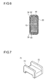
- Fig. 6 illustrates a modified example of the protecting member for the stator.
- the protecting member 60 including the end portions that are not inserted in the slot 38 (refer to Fig. 4 ) at all may be provided.
- the protecting member 60 for the stator does not enter the slot, so that a length of the protecting member 60 for the stator is zero in the area of the slot, and is shorter than the entire length of the tooth part 30.
- a width of the protecting member 60 for the stator is equal to a width of the tooth part 30, so that there are no spaces on the both sides of the tooth part 30, compared with Fig. 5 . Accordingly, the space of the slot 38 can be more effectively used than in the embodiment of Fig. 5 to improve the winding efficiency, and the heat radiation efficiency.
- wall portions 72 are provided at the inner position in the inward direction of the protecting member 70 for the stator and at the outer position in the outer direction thereof.
- the wall portions 72 extend from the protecting member 70 for the stator toward the outer side in the stacking direction.
- Fig. 7 illustrates another modified example 2 of the protecting member for the stator.
- the protecting member 70 for the stator includes the wall portions 72. Providing the wall portions 72 prevents a part of the wound electric wire 50 from being displaced in the inward direction or in the outward direction of the tooth part 30 when the electric wire 50 is wound around the tooth part 30.
Landscapes
- Engineering & Computer Science (AREA)
- Power Engineering (AREA)
- Insulation, Fastening Of Motor, Generator Windings (AREA)
- Iron Core Of Rotating Electric Machines (AREA)
Applications Claiming Priority (1)
| Application Number | Priority Date | Filing Date | Title |
|---|---|---|---|
| JP2011278701A JP2013132108A (ja) | 2011-12-20 | 2011-12-20 | 固定子 |
Publications (2)
| Publication Number | Publication Date |
|---|---|
| EP2608360A2 true EP2608360A2 (de) | 2013-06-26 |
| EP2608360A3 EP2608360A3 (de) | 2015-07-22 |
Family
ID=47355877
Family Applications (1)
| Application Number | Title | Priority Date | Filing Date |
|---|---|---|---|
| EP12196745.9A Withdrawn EP2608360A3 (de) | 2011-12-20 | 2012-12-12 | Stator und Statorschutzteil |
Country Status (4)
| Country | Link |
|---|---|
| US (1) | US9270147B2 (de) |
| EP (1) | EP2608360A3 (de) |
| JP (1) | JP2013132108A (de) |
| CN (1) | CN103178626B (de) |
Families Citing this family (4)
| Publication number | Priority date | Publication date | Assignee | Title |
|---|---|---|---|---|
| JP5727577B2 (ja) | 2013-11-11 | 2015-06-03 | ファナック株式会社 | コイル固定部品を備える電動機の固定子、電動機、及び単位コイルの固定方法 |
| JP6469954B2 (ja) * | 2014-03-07 | 2019-02-13 | オリエンタルモーター株式会社 | ハイブリッド型ステッピングモーター |
| EP3944465A1 (de) * | 2020-07-20 | 2022-01-26 | Siemens Aktiengesellschaft | Stator für eine gehäuselose dynamoelektrische rotatorische maschine |
| KR20240004547A (ko) * | 2021-04-26 | 2024-01-11 | 가부시키가이샤 에바라 세이사꾸쇼 | 모터 펌프 |
Citations (1)
| Publication number | Priority date | Publication date | Assignee | Title |
|---|---|---|---|---|
| JP2010279241A (ja) | 2009-04-30 | 2010-12-09 | Panasonic Corp | 電動機の固定子 |
Family Cites Families (13)
| Publication number | Priority date | Publication date | Assignee | Title |
|---|---|---|---|---|
| JP4501266B2 (ja) * | 2000-09-29 | 2010-07-14 | 株式会社富士通ゼネラル | 電動機 |
| JP3724446B2 (ja) * | 2002-04-01 | 2005-12-07 | 日産自動車株式会社 | モータの電機子構造 |
| DE102004011094A1 (de) * | 2004-03-06 | 2005-09-22 | Robert Bosch Gmbh | Hauptelement für eine elektrische Maschine |
| JP4826718B2 (ja) * | 2004-07-27 | 2011-11-30 | 日本電産株式会社 | モータ用の電機子およびモータ |
| KR20060027704A (ko) * | 2004-09-23 | 2006-03-28 | 엘지전자 주식회사 | 인슐레이터를 구비한 전동모터의 고정자 |
| JPWO2007043224A1 (ja) * | 2005-10-12 | 2009-04-16 | パナソニック株式会社 | 固定子及びこれを適用したモータ、及びこの固定子の製造方法 |
| WO2008027535A2 (en) * | 2006-09-01 | 2008-03-06 | Sears David B | Insulator for stator assembly of brushless dc motor |
| JP2008283730A (ja) * | 2007-05-08 | 2008-11-20 | Sumitomo Electric Ind Ltd | 電動機用分割固定子、この分割固定子を備える電動機用固定子、この電動機用固定子を備える電動機及び電動機用分割固定子の製造方法 |
| JP5151300B2 (ja) * | 2007-08-02 | 2013-02-27 | トヨタ自動車株式会社 | ステータおよび回転電機 |
| JP2010004637A (ja) * | 2008-06-19 | 2010-01-07 | Daikin Ind Ltd | インシュレータ、電機子及びモータ |
| CN201590692U (zh) | 2009-12-24 | 2010-09-22 | 中山大洋电机股份有限公司 | 一种电机拉伸端盖与定子的安装结构 |
| CN201590691U (zh) | 2009-12-24 | 2010-09-22 | 中山大洋电机股份有限公司 | 一种滚筒电机定子结构 |
| JP5626159B2 (ja) * | 2011-08-08 | 2014-11-19 | アイシン精機株式会社 | 車両用回転電機 |
-
2011
- 2011-12-20 JP JP2011278701A patent/JP2013132108A/ja active Pending
-
2012
- 2012-12-12 EP EP12196745.9A patent/EP2608360A3/de not_active Withdrawn
- 2012-12-19 US US13/720,207 patent/US9270147B2/en active Active
- 2012-12-20 CN CN201210557011.0A patent/CN103178626B/zh active Active
Patent Citations (1)
| Publication number | Priority date | Publication date | Assignee | Title |
|---|---|---|---|---|
| JP2010279241A (ja) | 2009-04-30 | 2010-12-09 | Panasonic Corp | 電動機の固定子 |
Also Published As
| Publication number | Publication date |
|---|---|
| CN103178626A (zh) | 2013-06-26 |
| CN103178626B (zh) | 2016-06-22 |
| EP2608360A3 (de) | 2015-07-22 |
| US20130154433A1 (en) | 2013-06-20 |
| US9270147B2 (en) | 2016-02-23 |
| JP2013132108A (ja) | 2013-07-04 |
Similar Documents
| Publication | Publication Date | Title |
|---|---|---|
| EP2320539B1 (de) | Drehmaschinenstator | |
| US20170237304A1 (en) | Stator for rotary electric machine | |
| JP4697545B2 (ja) | ステータ及び回転電機 | |
| JP4609190B2 (ja) | 車両用回転電機 | |
| KR20140115266A (ko) | 코일, 회전 전기 기계 및 회전 전기 기계의 제조 방법 | |
| CN111628593B (zh) | 定子、定子组件、电能与机械能的转换器 | |
| US10818427B2 (en) | Stator assembly including a bobbin having an extension tab and a retention rib | |
| US9270147B2 (en) | Stator and protecting member for stator | |
| CN103825377B (zh) | 定子 | |
| CN107302274B (zh) | 电动机的定子 | |
| CN111628594A (zh) | 电能与机械能的转换器 | |
| JP6469954B2 (ja) | ハイブリッド型ステッピングモーター | |
| JP6589571B2 (ja) | 回転電機のステータ | |
| JP6485548B2 (ja) | ステータおよびステータの製造方法 | |
| CN119213670A (zh) | 定子 | |
| CN112236925A (zh) | 旋转电机的定子以及旋转电机 | |
| JP2012105372A (ja) | 外転型の電動機 | |
| JP2011166859A (ja) | 回転電機 | |
| EP2605369A2 (de) | Stator | |
| JP6245018B2 (ja) | モータ | |
| JP7205454B2 (ja) | ステータ、ステータアッセンブリ、電気エネルギーと力学的エネルギーとの変換器 | |
| US20250219478A1 (en) | Stator and motor | |
| JP2013172479A (ja) | ステーター用インシュレーター | |
| JP2013055776A (ja) | 回転電機のステータ | |
| JP2013208039A (ja) | 回転電機 |
Legal Events
| Date | Code | Title | Description |
|---|---|---|---|
| AK | Designated contracting states |
Kind code of ref document: A2 Designated state(s): AL AT BE BG CH CY CZ DE DK EE ES FI FR GB GR HR HU IE IS IT LI LT LU LV MC MK MT NL NO PL PT RO RS SE SI SK SM TR |
|
| AX | Request for extension of the european patent |
Extension state: BA ME |
|
| PUAI | Public reference made under article 153(3) epc to a published international application that has entered the european phase |
Free format text: ORIGINAL CODE: 0009012 |
|
| PUAL | Search report despatched |
Free format text: ORIGINAL CODE: 0009013 |
|
| AK | Designated contracting states |
Kind code of ref document: A3 Designated state(s): AL AT BE BG CH CY CZ DE DK EE ES FI FR GB GR HR HU IE IS IT LI LT LU LV MC MK MT NL NO PL PT RO RS SE SI SK SM TR |
|
| AX | Request for extension of the european patent |
Extension state: BA ME |
|
| RIC1 | Information provided on ipc code assigned before grant |
Ipc: H02K 3/34 20060101ALN20150615BHEP Ipc: H02K 3/52 20060101ALN20150615BHEP Ipc: H02K 3/32 20060101AFI20150615BHEP |
|
| STAA | Information on the status of an ep patent application or granted ep patent |
Free format text: STATUS: THE APPLICATION IS DEEMED TO BE WITHDRAWN |
|
| 18D | Application deemed to be withdrawn |
Effective date: 20160123 |