EP3944465A1 - Stator für eine gehäuselose dynamoelektrische rotatorische maschine - Google Patents
Stator für eine gehäuselose dynamoelektrische rotatorische maschine Download PDFInfo
- Publication number
- EP3944465A1 EP3944465A1 EP20186687.8A EP20186687A EP3944465A1 EP 3944465 A1 EP3944465 A1 EP 3944465A1 EP 20186687 A EP20186687 A EP 20186687A EP 3944465 A1 EP3944465 A1 EP 3944465A1
- Authority
- EP
- European Patent Office
- Prior art keywords
- stator
- rotary machine
- slot
- caseless
- slot wedge
- Prior art date
- Legal status (The legal status is an assumption and is not a legal conclusion. Google has not performed a legal analysis and makes no representation as to the accuracy of the status listed.)
- Withdrawn
Links
Images


Classifications
-
- H—ELECTRICITY
- H02—GENERATION; CONVERSION OR DISTRIBUTION OF ELECTRIC POWER
- H02K—DYNAMO-ELECTRIC MACHINES
- H02K1/00—Details of the magnetic circuit
- H02K1/06—Details of the magnetic circuit characterised by the shape, form or construction
- H02K1/12—Stationary parts of the magnetic circuit
- H02K1/18—Means for mounting or fastening magnetic stationary parts on to, or to, the stator structures
-
- H—ELECTRICITY
- H02—GENERATION; CONVERSION OR DISTRIBUTION OF ELECTRIC POWER
- H02K—DYNAMO-ELECTRIC MACHINES
- H02K1/00—Details of the magnetic circuit
- H02K1/06—Details of the magnetic circuit characterised by the shape, form or construction
- H02K1/12—Stationary parts of the magnetic circuit
- H02K1/16—Stator cores with slots for windings
-
- H—ELECTRICITY
- H02—GENERATION; CONVERSION OR DISTRIBUTION OF ELECTRIC POWER
- H02K—DYNAMO-ELECTRIC MACHINES
- H02K1/00—Details of the magnetic circuit
- H02K1/06—Details of the magnetic circuit characterised by the shape, form or construction
- H02K1/12—Stationary parts of the magnetic circuit
- H02K1/20—Stationary parts of the magnetic circuit with channels or ducts for flow of cooling medium
-
- H—ELECTRICITY
- H02—GENERATION; CONVERSION OR DISTRIBUTION OF ELECTRIC POWER
- H02K—DYNAMO-ELECTRIC MACHINES
- H02K5/00—Casings; Enclosures; Supports
- H02K5/04—Casings or enclosures characterised by the shape, form or construction thereof
- H02K5/15—Mounting arrangements for bearing-shields or end plates
-
- H—ELECTRICITY
- H02—GENERATION; CONVERSION OR DISTRIBUTION OF ELECTRIC POWER
- H02K—DYNAMO-ELECTRIC MACHINES
- H02K5/00—Casings; Enclosures; Supports
- H02K5/04—Casings or enclosures characterised by the shape, form or construction thereof
- H02K5/18—Casings or enclosures characterised by the shape, form or construction thereof with ribs or fins for improving heat transfer
Definitions
- the invention relates to a stator for a caseless dynamoelectric rotary machine and a caseless dynamoelectric rotary machine.
- a central aspect of new environmental guidelines concerns the repairability of products. Electric motors are also affected.
- the tasks of a housing of an electric motor include, for. B. a cooling of the electric motor.
- a damaged housing is often a reason to dispose of the electric motor, as repairs are sometimes difficult.
- the object of the invention is to improve an electric motor in terms of repairability.
- stator for a caseless dynamoelectric rotary machine, the stator having a material layer structure, the material layer structure having a plurality of material layers, the material layers being lined up along an axis of rotation, the material layer structure having a plurality of thickened areas and a plurality of grooves, wherein one Groove is arranged between two thickenings.
- the material layer structure advantageously has the function of a laminated core and is advantageously designed as a laminated core (also: stator core).
- the material layer advantageously has the function of a preferably stamped individual sheet and is advantageously designed as a single sheet.
- the thickened areas are at least partially designed as cooling fins.
- This increase in surface area allows heat to be dissipated in a simple manner.
- At least one groove is designed in such a way that at least one slot wedge can be accommodated, with at least one thickened portion being designed in such a way that the slot wedge can be fixed.
- a first thickened portion at a radial end of the first thickened portion has a projection directed in the direction of rotation, with a second thickened portion at a radial end of the second thickened portion having a projection directed counter to the direction of rotation.
- the material layers are materially connected, in particular by means of an adhesive.
- the individual laminations are advantageously linked to one another to form a stator iron packet during a stamping process or after stamping. This works particularly well by gluing the individual sheets over the entire surface.
- Full-surface bonding also offers the advantage that the individual sheets are sealed to one another. In this way, good protection against contact, foreign bodies and water is achieved.
- stator is coated with a coating.
- the coating advantageously ensures protection against corrosion, in particular on an outer circumference of the stator.
- the coating is suitable for forming an insulating layer between the winding and the material layer, in particular the stator lamination, in an inner region of the slots.
- a galvanic coating a coating by thermal flame spraying or cold gas spraying as well as a coating by a dipping process (e.g. galvanizing).
- only one type of coating is used, which is suitable for the outer area of the stator as well as for the inner area.
- a resin-based coating which is applied by painting or dipping, for example, is particularly suitable for this purpose.
- Electrostatic powder coating e.g. with subsequent thermal treatment is another option.
- the coating advantageously has a thickness of between 20 ⁇ m and 70 ⁇ m, in particular between 30 ⁇ m and 60 ⁇ m.
- a coating is conceivable that has lacquer and/or resin. These can be based on polyester (unsaturated) and/or epoxy. Silicones are also conceivable.
- stator z. B. Due to the coating of the stator z. B. protected against corrosion and thus rusting. This succeeds z. B. by immersion in an anti-rust substrate and / or by painting with the anti-rust substrate.
- electrical insulation can be generated by the coating. This is done, for example, by fillers in the coating.
- Ceramic fillers are advantageously used here to improve resistance to abrasion, preferably on the outside. Ceramic fillers can also be used to increase insulating ability and heat conduction, especially in a slot area for the winding.
- Thermally conductive particles e.g. quartz sand, or particles resistant to partial discharge, in particular based on silicon, are also suitable as fillers.
- a caseless dynamo-electric rotary machine comprising such a stator, an end element being arranged at at least one axial end of the stator, the end element being connected to the stator by means of at least one connecting element.
- the dynamoelectric rotary machine without a housing can also be referred to as a one-piece stator-housing unit, since a function of the housing is implemented in particular on an outer circumference of the stator.
- a conventional housing is dispensed with.
- the housing is designed to be integrated into the stator, with special contours and ribs being punched into the individual sheet metal during the stamping process.
- one end element each is arranged at a front axial end of the stator and at a rear axial end of the stator.
- the end element is designed as a bearing plate.
- the end shield advantageously has a receptacle for a bearing for supporting a shaft of the rotor.
- the caseless dynamoelectric rotary machine has an end shield on an A side and an end shield on a B side.
- the end element has thickenings, in particular designed as cooling ribs.
- End windings which are preferably positioned axially below the end element, their Dissipate heat thus better. In this way, efficiency can be increased.
- the cooling ribs of the stator and the cooling ribs of the end element are advantageously arranged in alignment.
- the connecting element is a screw element.
- the screw element is preferably a clamping screw.
- At least one slot wedge is arranged in at least one slot of the stator.
- Exactly one slot wedge is advantageously arranged in a slot. However, there can also be several slot wedges per slot.
- the connecting element is connected to at least one slot wedge.
- stator is connected to the end element.
- the end element is advantageously connected to the stator at at least two points. This is advantageously achieved by means of two slot wedges, which are arranged at a distance from an outer circumference of the stator.
- At least one base is connected to at least one slot wedge.
- stator is connected to the base.
- At least two feet are advantageously connected to the stator. This is advantageously achieved by means of two slot wedges which are spaced apart with respect to an outer circumference of the stator are arranged. These are advantageously located on an underside of the stator.
- the feet can z. However, it can also be arranged laterally, for example, in the case of stators to be mounted on a wall.
- a recording of components such as end shields and feet is thus realized by introduced slot wedges.
- the end element has a connection box for supplying electrical energy.
- connection box advantageously has a base and is designed for connection to a terminal box.
- the slot wedge is arranged at a distance from the front axial end of the stator and/or from the rear axial end of the stator.
- a groove base that is free in this way enables the end elements, in particular end shields, to be centered. No further processing is required
- the groove is preferably designed as a keyway.
- the invention offers the advantage that recycling is simplified since there is no housing.
- a winding can e.g. B. removed from the stator core in case of damage and introduced a new winding. It is therefore easy to reuse the stator pack with the integrated housing.
- the invention also offers the advantage that it is not necessary to process the centerings.
- groove bases used in the stator For this purpose, groove bases used in the stator. An accuracy of coaxiality is very high due to the punching of the individual sheets.
- annular surface of the wall can also be used on the active part.
- machine can be designed as short as possible with different, performance-related package lengths within one axle height.
- a machine length is not dependent on a housing.
- the end shield is not attached to a housing surface, but directly to the material layer structure, in particular to the laminated core.
- stator it is possible by the invention to increase an outer diameter of the stator.
- a larger stator outer diameter makes it possible to make a rotor outer diameter just as larger and thus achieve higher performance and higher efficiency.
- the invention allows construction of a compact and efficient motor.
- the invention is suitable for all areas of application of dynamo-electric rotating machines, in particular for industrial applications such as pump, fan, compressor drives and for conveyor systems.
- FIG 1 shows a dynamoelectric rotary machine 1 without a housing.
- the machine 1 comprises a stator 2, a rotor 3 and a shaft 4.
- the stator 2 comprises a material layer structure, in particular a laminated core 8 (also: stator core).
- a laminated core 8 also: stator core
- thickenings in the form of cooling fins 9 are formed on an outer circumference 52 of the stator 2, in particular on an outer circumference of the laminated core 8.
- thickenings in the form of cooling fins 9 are formed on an outer circumference 52 of the stator 2, in particular on an outer circumference of the laminated core 8.
- further thickenings in the form of a groove wedge receiving element 10 are formed on the outer circumference. Lying in between a groove 5 is executed.
- the figure also shows a plurality of slot wedges 12 and a plurality of feet 13.
- a bearing plate 14 is arranged on a front axial end of the stator 50, and a further bearing plate is preferably also formed on a rear axial end 51 (not shown).
- the figure also shows that the end shield 14 also has cooling ribs 141 .
- the bearing plate 14 also includes a terminal box 21.
- the bearing plate 14 also has a wedge receiving element 142. Possible types of attachment of the end shield 14 and the feet 13 is in the figures 5 and 6 explained in more detail.
- the enveloping dimensions are no larger than for a machine with a housing.
- the invention simplifies recycling and processing of engine components.
- FIG 2 shows a contour of a single sheet 6.
- the single sheet 6 has a specific contour.
- the contour has indentations and bulges on its outer circumference, which are used to form cooling fins 9 and grooves 7 , as well as further indentations and further bulges, which are used to form the slot wedge receiving elements 10 and grooves 5 .
- the individual sheet 6 is preferably produced by stamping from, preferably rolled, large sheet.
- FIG. 3 shows a plurality of individual sheets 6, which are lined up to form a laminated core 8.
- the individual sheets are preferably glued to one another over their entire surface.
- the cooling fins 9 are advantageously produced by stamping. Cooling is thus integrated in the stator 2. The heat transfer from the stator 2 to the cooling fins 9 is therefore optimal.
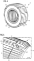
- FIG 4 shows the laminated core 8, having four slot wedge receiving elements 10.
- a slot wedge 12 is arranged in the figure. Only one slot wedge 12 is advantageously arranged per slot wedge receiving element 10 . It is however, it is also possible to arrange a plurality of slot wedges 12 in a slot wedge receiving element 10 .
- the slot wedge 12 has at least one bore 121, 122, 123 or other indentations. This is used, for example, to attach other components.
- a bore 121 is advantageously formed at one axial end, preferably at both axial ends.
- the figure also shows two bores 122, 123 at the radial end of the slot wedge 12.
- the slot wedge 12 is to the front axial end of the stator 50 (see Fig. FIG 1 ) and/or spaced apart from the rear axial end of the stator 51 .
- a groove base 17 that is free in this way enables the end elements, in particular end shields 14, to be centered. No further processing is required for centering.
- FIG. 5 shows an attachment of an end element, designed as a bearing plate 14, on the stator 2.
- a slot wedge 12 is arranged in the slot wedge receiving element 10.
- a fastening 16 is arranged in the slot wedge element 142 of the bearing plate 14 . This serves to fasten the end shield 14 to the stator 2. For example, this is a clamping screw. Fastening the end shields 14 using slot wedges 12 is advantageous since the machine 1 can thus be constructed in a particularly compact manner.
- the slot wedges 12 are advantageously shorter than the stator core 8 .
- This enables axial bracing of the end shields 14 on the end faces of the stator core 8.
- the machine 1 is therefore suitable for protection classes IP54 and IP55.
- a foamed seal can also be introduced into the gap 22 .
- FIG. 6 shows the machine 1, having feet 13.
- the feet 13 are also fastened by the slot wedges 12.
- radial threads are designed in the slot wedge 12 for fastening the foot 13 or for receiving a lifting eyelet.
- the machine 1 stands securely thanks to foot support on cooling fins 9 and bracing with the slot wedge 12 .
- a foot is advantageously fastened to the slot wedges 12.
- the feet 13 are advantageously guided in the slot 5. This means that an embodiment with and without a foot can be easily implemented or retrofitted. Machining is not required due to the accuracy of the stamping process.
- FIG 7 shows the bearing plate 14.
- the bearing plate 14 has a plurality of cooling ribs 141 and four slot wedge receiving elements 142.
- the bearing plate 14 comprises, preferably on an upper side of the bearing plate 14, a terminal box base 21.
- a sealing of a connection point between the bearing plate 14 and the laminated core 8 succeeds for example by means of an O-ring, which is arranged, for example, on an end face of the laminated core 8 .
- the fastening cam 15 is designed, in particular by a notch 18, in such a way that water drainage on the fastening cam 15 in the end shield 14 is optimal.
- the fastening cam 15 protrudes beyond an axial end of the end shield 14 .
- the fastening cam 15 advantageously protrudes into the groove 5 or engages in the groove 5 . This enables centering.
- the 10 shows the machine 1, having a hood 23.
- the machine 1 is preferably self-ventilated and advantageously has a fan (not shown).
- the hood 23 serves to shield the fan.
- the snap connection 20 enables attachment of the hood 23.
- Other types of connection are also conceivable.
Abstract
Die Erfindung betrifft einen Stator (2) für eine gehäuselose dynamoelektrische rotatorische Maschine (1), wobei der Stator (2) ein Materiallagengefüge (8) aufweist, wobei das Materiallagengefüge (8) eine Mehrzahl an Materiallagen (6) aufweist, wobei die Materiallagen (6) entlang einer Rotationsachse aneinandergereiht sind, wobei das Materiallagengefüge (8) eine Mehrzahl an Aufdickungen (9, 10) und eine Mehrzahl an Nuten (5, 7) aufweist, wobei eine Nut (5, 7) zwischen zwei Aufdickungen (9, 10) angeordnet ist. Die Erfindung betrifft überdies eine gehäuselose dynamoelektrische rotatorische Maschine (1), aufweisend einen derartigen Stator (2), wobei an wenigstens einem axialen Ende (50, 51) des Stators (2) ein Endelement (14) angeordnet ist, wobei das Endelement (14) mittels wenigstens eines Verbindungselements (16) mit dem Stator (2) verbunden ist.
Description
- Die Erfindung betrifft einen Stator für eine gehäuselose dynamoelektrische rotatorische Maschine sowie eine gehäuselose dynamoelektrische rotatorische Maschine.
- Ein zentraler Aspekt neuer Umweltrichtlinien betrifft eine Reparierbarkeit von Produkten. Auch Elektromotoren sind hiervon betroffen.
- Zu den Aufgaben eines Gehäuses eines Elektromotors gehört z. B. eine Kühlung des Elektromotors. Jedoch ist ein beschädigtes Gehäuse oftmals ein Grund, den Elektromotor zu entsorgen, da sich eine Reparatur mitunter schwierig gestaltet.
- Der Erfindung liegt die Aufgabe zugrunde, einen Elektromotor hinsichtlich Reparierbarkeit zu verbessern.
- Die Lösung der Aufgabe gelingt durch Anspruch 1, d. h. einen Stator für eine gehäuselose dynamoelektrische rotatorische Maschine, wobei der Stator ein Materiallagengefüge aufweist, wobei das Materiallagengefüge eine Mehrzahl an Materiallagen aufweist, wobei die Materiallagen entlang einer Rotationsachse aneinandergereiht sind, wobei das Materiallagengefüge eine Mehrzahl an Aufdickungen und eine Mehrzahl an Nuten aufweist, wobei eine Nut zwischen zwei Aufdickungen angeordnet ist.
- Das Materiallagengefüge hat vorteilhaft die Funktion eines Blechpakets inne und ist vorteilhaft als Blechpaket (auch: Statorpaket) ausgeführt. Die Materiallage hat vorteilhaft die Funktion eines, vorzugsweise gestanzten, Einzelblechs inne und ist vorteilhaft als Einzelblech ausgeführt.
- In einer vorteilhaften Ausführung sind die Aufdickungen wenigstens teilweise als Kühlrippen ausgebildet.
- Durch diese Oberflächenvergrößerung wird Wärme auf einfache Weise abgeführt.
- In einer vorteilhaften Ausführung ist wenigstens eine Nut derart ausgebildet, dass wenigstens ein Nutkeil aufnehmbar ist, wobei wenigstens eine Aufdickung derart ausgebildet ist, dass der Nutkeil fixierbar ist.
- In einer vorteilhaften Ausführung weist zur Fixierung des Nutkeils eine erste Aufdickung an einem radialen Ende der ersten Aufdickung einen in Rotationsrichtung gerichteten Vorsprung auf, wobei eine zweite Aufdickung an einem radialen Ende der zweiten Aufdickung einen entgegen der Rotationsrichtung gerichteten Vorsprung aufweist.
- In einer vorteilhaften Ausführung sind die Materiallagen stoffschlüssig, insbesondere mittels eines Klebstoffes, verbunden.
- Vorteilhaft werden die Einzelbleche während eines Stanzprozesses oder nach dem Stanzen miteinander zu einem Stator-Eisenpaket verknüpft. Dies gelingt besonders gut durch vollflächiges Verkleben der Einzelbleche.
- Vollflächiges Verkleben bietet zudem den Vorteil, dass die Einzelbleche zueinander abgedichtet sind. Auf diese Weise wird ein guter Schutz gegen Berührung, Fremdköper und Wasser erreicht.
- In einer vorteilhaften Ausführung ist der Stator mit einer Beschichtung beschichtet.
- Die Beschichtung gewährleistet vorteilhaft einen Korrosionsschutz, insbesondere an einem Außenumfang des Stators.
- Ferner ist die Beschichtung geeignet, in einem innenliegenden Bereich der Nuten eine Isolationsschicht zwischen Wicklung und Materiallage, insbesondere Statorblech, zu bilden.
- Am Außenumfang ist z. B. eine Metall aufweisende Beschichtung möglich. Es sind denkbar: Eine galvanische Beschichtung, eine Beschichtung durch thermisches Flammspritzen oder Kaltgasspritzen sowie eine Beschichtung durch ein Tauchverfahren (z.B. Verzinken).
- Vorzugsweise wird nur eine Beschichtungsart angewandt, die für außenliegende Bereich des Stators sowie für innenliegende Bereiche geeignet ist. Besonders gut eignet sich hierfür eine Beschichtung auf Harzbasis, die beispielsweise durch Lackieren oder Tauchen aufgebracht wird. Eine elektrostatisches Pulverbeschichtung (z. B. mit einer anschließenden thermischen Behandlung) stellt eine weitere Möglichkeit dar.
- Die Beschichtung weist vorteilhaft eine Dicke zwischen 20 µm und 70 µm auf, insbesondere zwischen 30 µm und 60 µm.
- Ferner ist eine Beschichtung denkbar, die Lack und/oder Harz aufweist. Diese können auf Polyester- (ungesättigt) und/oder Epoxidbasis sein. Es sind auch Silikone denkbar.
- Durch die Beschichtung ist der Stator z. B. gegen Korrosion und somit Rostbildung geschützt. Dies gelingt z. B. durch Tauchen in ein Rostschutzsubstrat und/oder durch Lackieren mit dem Rostschutzsubstrat.
- Überdies kann eine elektrische Isolation durch die Beschichtung erzeugt werden. Dies erfolgt z.B. durch Füllstoffe in der Beschichtung.
- Vorteilhaft werden hierbei zur Verbesserung gegen Abrieb, vorzugsweise im Außenbereich, keramische Füllstoffe verwendet. Keramische Füllstoffe können auch zur Steigerung einer Isolationsfähigkeit und Wärmeleitung, insbesondere in einem Nutbereich für die Wicklung, verwendet werden.
- Als Füllstoffe eignen sich zudem wärmeleitfähige Partikel, z.B. Quarzsand, oder teilentladungsbeständige Partikel, insbesondere auf Siliziumbasis.
- Die Lösung der oben gestellten Aufgabe gelingt ferner durch Anspruch 7, d. h. eine gehäuselose dynamoelektrische rotatorische Maschine, aufweisend einen derartigen Stator, wobei an wenigstens einem axialen Ende des Stators ein Endelement angeordnet ist, wobei das Endelement mittels wenigstens eines Verbindungselements mit dem Stator verbunden ist.
- Die gehäuselose dynamoelektrische rotatorische Maschine kann auch als einstückige Stator-Gehäuse-Einheit bezeichnet werden, da eine Funktion des Gehäuses insbesondere an einem Außenumfang des Stators realisiert ist.
- Erfindungsgemäß wird auf ein konventionelles Gehäuse verzichtet. Das Gehäuse ist in den Stator integriert ausgeführt, indem spezielle Konturen sowie Rippen in das Einzelblech während des Stanzprozesses gestanzt werden.
- In einer vorteilhaften Ausführung ist an einem vorderen axialen Ende des Stators und an einem hinteren axialen Ende des Stators je ein Endelement angeordnet.
- In einer vorteilhaften Ausführung ist das Endelement als Lagerschild ausgeführt.
- Das Lagerschild weist vorteilhaft eine Aufnahme für ein Lager zur Lagerung einer Welle des Rotors auf. Vorteilhaft weist die gehäuselose dynamoelektrische rotatorische Maschine ein Lagerschild an einer A-Seite und ein Lagerschild an einer B-Seite auf.
- Vorteilhaft weist das Endelement Aufdickungen, insbesondere als Kühlrippen ausgeführt, auf. Wickelköpfe, die vorzugsweise axial unter dem Endelement positioniert sind, können ihre Verlustwärme somit besser abgeben. Auf diese Weise kann ein Wirkungsgrad gesteigert werden.
- Die Kühlrippen des Stators und die Kühlrippen des Endelements sind vorteilhaft in einer Flucht angeordnet.
- In einer vorteilhaften Ausführung ist das Verbindungselement ein Schraubelement. Das Schraubelement ist vorzugsweise eine Spannschraube.
- In einer vorteilhaften Ausführung ist wenigstens ein Nutkeil in wenigstens einer Nut des Stators angeordnet.
- Vorteilhaft ist genau ein Nutkeil in einer Nut angeordnet. Es können jedoch auch mehrere Nutkeile pro Nut vorhanden sein.
- In einer vorteilhaften Ausführung ist das Verbindungselement mit wenigstens einem Nutkeil verbunden.
- So gelingt eine optimale Verspannung zwischen Lagerschild und Stator.
- Auf diese Weise wird der Stator mit dem Endelement verbunden. Vorteilhaft ist das Endelement an wenigstens zwei Stellen mit dem Stator verbunden. Dies gelingt vorteilhaft mittels zweier Nutkeile, welche bezüglich eines Außenumfangs des Stators beabstandet angeordnet sind.
- Aus Zentriergründen sind vier Stellen jedoch bevorzugt.
- In einer vorteilhaften Ausführung ist wenigstens ein Standfuß mit wenigstens einem Nutkeil verbunden.
- Auf diese Weise wird der Stator mit dem Standfuß verbunden. Vorteilhaft sind wenigsten zwei Standfüße mit dem Stator verbunden. Dies gelingt vorteilhaft mittels zweier Nutkeile, welche bezüglich eines Außenumfangs des Stators beabstandet angeordnet sind. Diese befinden sich vorteilhaft an einer Unterseite des Stators.
- Die Standfüße können z. B. bei an einer Wand zu montierenden Statoren jedoch auch seitlich angeordnet sein.
- Eine Aufnahme von Bauteilen wie Lagerschilde und Standfüßen wird somit durch eingebrachte Nutkeile realisiert.
- Da eine Position der Nut für den Nutkeil durch den Stanzprozess sehr genau ist, ist eine Bearbeitung der Standfüße an der Unterseite nicht erforderlich.
- In einer vorteilhaften Ausführung weist das Endelement einen Anschlusskasten zur Versorgung mit elektrischer Energie auf.
- Der Anschlusskasten weist vorteilhaft einen Sockel auf und ist zur Verbindung mit einem Klemmkasten ausgebildet.
- In einer vorteilhaften Ausführung ist der Nutkeil zum vorderen axialen Ende des Stators und/oder zum hinteren axialen Ende des Stators beabstandet angeordnet.
- Eine auf diese Weise freie Nutgrundfläche ermöglicht eine Zentrierung der Endelemente, insbesondere Lagerschilde. Es ist keine weitere Bearbeitung erforderlich
- Die Nut ist hierzu vorzugsweise als Keilnut ausgeführt.
- Die Erfindung bietet den Vorteil, dass ein Recycling vereinfacht wird, da kein Gehäuse vorhanden ist. Eine Wicklung kann z. B. bei Beschädigung aus dem Statorpaket entfernt und eine neue Wicklung eingebracht werden. Eine Wiederverwendung des Statorpakets mit dem integrierten Gehäuse ist somit leicht möglich.
- Die Erfindung bietet zudem den Vorteil, dass eine Bearbeitung von Zentrierungen nicht erforderlich ist. Hierzu werden Nutgrundflächen im Stator genutzt. Eine Genauigkeit einer Koaxialität ist durch das Stanzen der Einzelbleche sehr hoch.
- Durch den Entfall des Gehäuses kann eine Ringfläche der Wandung zusätzlich am Aktivteil genutzt werden.
- Dies ist vorteilhaft, da die Maschine mit verschiedenen, leistungsbezogenen Paketlängen innerhalb einer Achshöhe, möglichst kurz ausgeführt sein kann. Eine Maschinenlänge ist so nicht abhängig von einem Gehäuse.
- Das Lagerschild wird nicht an einer Gehäusefläche befestigt, sondern direkt am Materiallagengefüge, insbesondere am Blechpaket.
- Es ist durch die Erfindung möglich, einen Außendurchmesser des Stators zu vergrößern. Durch einen größeren Stator-Außendurchmesser besteht die Möglichkeit, einen Rotor-Außendurchmesser ebenso größer zu gestalten und somit eine höhere Leistung bzw. einen höheren Wirkungsgrad zu erzielen. Eine optimale Wärmeabfuhr ist zudem gegeben. Da eine Abmessung einer Achshöhe jedoch nicht vergrößert werden muss, erlaubt die Erfindung den Bau eines kompakten und effizienten Motors.
- Die Erfindung eignet sich für sämtliche Anwendungsgebiete von dynamoelektrischen rotatorischen Maschinen, insbesondere für Industrieanwendungen wie Pumpen-, Lüfter-, Kompressor-Antriebe sowie für Förderanlagen.
- Im Folgenden wird die Erfindung anhand der in den Figuren gezeigten Beispielen näher beschrieben und erläutert. Es zeigen:
- FIG 1
- eine gehäuselose dynamoelektrische rotatorische Maschine,
- FIG 2
- eine Kontur eines Einzelblechs,
- FIG 3
- ein Blechpaket,
- FIG 4
- das Blechpaket mit vier Nutkeilaufnahmeelementen,
- FIG 5
- eine Befestigung eines Endelementes, ausgeführt als Lagerschild am Stator,
- FIG 6
- die dynamoelektrische rotatorische Maschine mit Standfüßen,
- FIG 7
- das Lagerschild,
- FIG 8
- einen Ausschnitt des Lagerschilds,
- FIG 9
- einen weiteren Ausschnitt des Lagerschilds,
- FIG 10
- die dynamoelektrische rotatorische Maschine mit einer Haube,
- FIG 11
- eine Schnappverbindung.
-
FIG 1 zeigt eine gehäuselose dynamoelektrische rotatorische Maschine 1. Die Maschine 1 umfasst einen Stator 2, einen Rotor 3 sowie eine Welle 4. Der Stator 2 umfasst ein Materiallagengefüge, insbesondere ein Blechpaket 8 (auch: Statorpaket). An einem Außenumfang 52 des Stators 2, insbesondere an einem Außenumfang des Blechpakets 8, sind Aufdickungen in Form von Kühlrippen 9 ausgebildet. Zwischen zwei Kühlrippen befindet sich eine Nut 7. Zudem sind am Außenumfang weitere Aufdickungen in Form eines Nutkeilaufnahmeelements 10 ausgebildet. Dazwischen liegend ist eine Nut 5 ausgeführt. - Die Figur zeigt zudem eine Mehrzahl an Nutkeilen 12 sowie eine Mehrzahl an Standfüßen 13. An einem vorderen axialen Ende des Stators 50 ist ein Lagerschild 14 angeordnet, vorzugsweise ist zudem an einem hinteren axialen Ende 51 ein weiteres Lagerschild ausgebildet (nicht dargestellt).
- Die Figur zeigt ferner, dass auch das Lagerschild 14 Kühlrippen 141 aufweist. Das Lagerschild 14 umfasst ferner einen Anschlusskasten 21. Das Lagerschild 14 weist zudem ein Nutkeilaufnahmeelement 142 auf. Mögliche Befestigungsarten des Lagerschilds 14 bzw. der Standfüße 13 wird in den
Figuren 5 bzw. 6 näher erläutert. - Durch Vergrößerung der Außendurchmesser am Stator und Rotor ist es möglich, die Maschine kompakter auf die Achshöhe bezogene Leistung zu gestalten. Die Hüllmaße sind dabei nicht größer als bei einer Maschine mit Gehäuse.
- Ein Recycling sowie eine Aufbereitung von Motorbauteilen werden durch die Erfindung vereinfacht.
-
FIG 2 zeigt eine Kontur eines Einzelblechs 6. Das Einzelblech 6 weist eine bestimmte Kontur auf. Die Kontur weist an ihrem Außenumfang Einbuchtungen und Ausbuchtungen auf, welche der Bildung von Kühlrippen 9 und Nuten 7 dienen, sowie weitere Einbuchtungen und weitere Ausbuchtungen, welche der Bildung der Nutkeilaufnahmeelemente 10 und Nuten 5 dienen. - Das Einzelblech 6 ist vorzugsweise mittels Stanzen aus, vorzugsweise gewalztem, Großblech hergestellt.
-
FIG 3 zeigt eine Mehrzahl an Einzelblechen 6, welche zur Bildung eines Blechpakets 8 aneinandergereiht sind. Die Einzelbleche sind vorzugsweise vollflächig miteinander verklebt. - Die Kühlrippen 9 werden vorteilhaft durch Stanzen hergestellt. Eine Kühlung ist somit im Stator 2 integriert. Der Wärmeübergang von Stator 2 zu den Kühlrippen 9 ist somit optimal.
-
FIG 4 zeigt das Blechpaket 8, aufweisend vier Nutkeilaufnahmeelemente 10. In jedem Nutkeilaufnahmeelement 10 ist in der Figur ein Nutkeil 12 angeordnet. Vorteilhaft ist pro Nutkeilaufnahmeelement 10 nur ein Nutkeil 12 angeordnet. Es ist jedoch auch möglich, in einem Nutkeilaufnahmeelement 10 mehrere Nutkeile 12 anzuordnen. Der Nutkeil 12 weist, wie in der Figur gezeigt, wenigstens eine Bohrung 121, 122, 123 oder anderweitige Vertiefungen auf. Dies dient beispielsweise einer Befestigung anderer Bauteile. Vorteilhaft ist eine Bohrung 121 an einem axialen Ende, vorzugsweise an beiden axialen Enden, ausgebildet. Die Figur zeigt ferner zwei Bohrungen 122, 123 am radialen Ende des Nutkeils 12. - Der Nutkeil 12 ist zum vorderen axialen Ende des Stators 50 (s.
FIG 1 ) und/oder zum hinteren axialen Ende des Stators 51 beabstandet angeordnet. Eine auf diese Weise freie Nutgrundfläche 17 ermöglicht eine Zentrierung der Endelemente, insbesondere Lagerschilde 14. Es ist keine weitere Bearbeitung zur Zentrierung erforderlich. -
FIG 5 zeigt eine Befestigung eines Endelementes, ausgeführt als Lagerschild 14, am Stator 2. Im Nutkeilaufnahmeelement 10 ist ein Nutkeil 12 angeordnet. Im Nutkeilelement 142 des Lagerschilds 14 ist eine Befestigung 16 angeordnet. Dies dient einer Befestigung des Lagerschilds 14 am Stator 2. Beispielsweise handelt es sich hierbei um eine Spannschraube. Eine Befestigung der Lagerschilde 14 durch Nutkeile 12 ist vorteilhaft, da die Maschine 1 somit besonders kompakt gebaut werden kann. - Die Nutkeile 12 sind vorteilhaft kürzer als das Statorpaket 8 ausgeführt. Dies ermöglicht beim Befestigen der Lagerschilde 14, insbesondere mittels einer axialen Verschraubung in die Nutkeile 12, eine axiale Verspannung der Lagerschilde 14 an den Stirnseiten des Statorpakets 8.
- Eine Abdichtung von Stator und Lagerschild gelingt besonders gut durch einen O-Ring, der in einen Spalt 22 eingebracht wird. Auf diese Weise ist die Maschine besonders gut gegen Fremdkörper und Berührung sowie Wasser geschützt. Die Maschine 1 weist somit eine Eignung für die Schutzklassen IP54 und IP55 auf.
- Auch eine geschäumte Dichtung kann in den Spalt 22 eingebracht werden.
-
FIG 6 zeigt die Maschine 1, aufweisend Standfüße 13. Auch die Befestigung der Standfüße 13 gelingt durch die Nutkeile 12. Vorteilhaft sind radiale Gewinde im Nutkeil 12 zur Befestigung des Standfußes 13 bzw. zur Aufnahme einer Hebeöse ausgeführt. Durch eine Fußabstützung an Kühlrippen 9 und eine Verspannung mit dem Nutkeil 12 steht die Maschine 1 sicher. - Eine Fußbefestigung erfolgt vorteilhaft an den Nutkeilen 12. Geführt werden die Standfüße 13 vorteilhaft in der Nut 5. Somit ist eine Ausführung mit und ohne Fuß einfach realisierbar, bzw. auch nachrüstbar, Eine Bearbeitung ist aufgrund der vorhandenen Genauigkeit aus dem Stanzprozess nicht erforderlich.
-
FIG 7 zeigt das Lagerschild 14. Das Lagerschild 14 weist eine Mehrzahl an Kühlrippen 141 auf sowie vier Nutkeilaufnahmeelemente 142. Das Lagerschild 14 umfasst, vorzugsweise an einer Oberseite des Lagerschilds 14, einen Anschlusskastensockel 21. Eine Abdichtung einer Verbindungsstelle des zwischen Lagerschild 14 und Blechpaket 8 gelingt, beispielsweise mittels eines O-Rings, der beispielsweise auf einer Stirnseite des Blechpakets 8 angeordnet ist. -
FIG 8 und FIG 9 zeigen einen Ausschnitt des Lagerschilds 14 sowie eine Befestigungsnocke 15 aus verschiedenen Perspektiven. Die Befestigungsnocke 15 ist, insbesondere durch eine Einkerbung 18, derart ausgeführt, dass ein Wasserablauf an der Befestigungsnocke 15 im Lagerschild 14 optimal ist. Die Befestigungsnocke 15 ragt über ein axiales Ende des Lagerschilds 14 hinaus. Beim Zusammenfügen von Lagerschild 14 und Stator 2 ragt vorteilhaft die Befestigungsnocke 15 in die Nut 5 hinein bzw. greift in die Nut 5 ein. Dies ermöglicht eine Zentrierung. -
FIG 10 zeigt die Maschine 1, aufweisend eine Haube 23. Die Maschine 1 ist vorzugsweise eigenbelüftet ausgeführt und weist vorteilhaft einen Lüfter auf (nicht dargestellt). Die Haube 23 dient einer Abschirmung des Lüfters. -
FIG 11 zeigt eine Schnappverbindung 20. Die Schnappverbindung 20 ermöglicht eine Befestigung der Haube 23. Auch andere Verbindungsarten sind denkbar.
Claims (15)
- Stator (2) für eine gehäuselose dynamoelektrische rotatorische Maschine (1), wobei der Stator (2) ein Materiallagengefüge (8) aufweist, wobei das Materiallagengefüge (8) eine Mehrzahl an Materiallagen (6) aufweist, wobei die Materiallagen (6) entlang einer Rotationsachse aneinandergereiht sind, wobei das Materiallagengefüge (8) eine Mehrzahl an Aufdickungen (9, 10) und eine Mehrzahl an Nuten (5, 7) aufweist, wobei eine Nut (5, 7) zwischen zwei Aufdickungen (9, 10) angeordnet ist.
- Stator (2) nach Anspruch 1, wobei die Aufdickungen (9, 10) wenigstens teilweise als Kühlrippen ausgebildet sind.
- Stator (2) nach einem der vorhergehenden Ansprüche, wobei wenigstens eine Nut (5, 7) derart ausgebildet ist, dass wenigstens ein Nutkeil (12) aufnehmbar ist, wobei wenigstens eine Aufdickung (9, 10) derart ausgebildet ist, dass der Nutkeil (12) fixierbar ist.
- Stator (2) nach Anspruch 3, wobei zur Fixierung des Nutkeils (12) eine erste Aufdickung an einem radialen Ende der ersten Aufdickung einen in Rotationsrichtung gerichteten Vorsprung aufweist, wobei eine zweite Aufdickung an einem radialen Ende der zweiten Aufdickung einen entgegen der Rotationsrichtung gerichteten Vorsprung aufweist.
- Stator (2) nach einem der vorhergehenden Ansprüche, wobei die Materiallagen (6) stoffschlüssig, insbesondere mittels eines Klebstoffes, verbunden sind.
- Stator (2) nach einem der vorhergehenden Ansprüche, wobei der Stator (2) mit einer Beschichtung beschichtet ist.
- Gehäuselose dynamoelektrische rotatorische Maschine (1), aufweisend einen Stator (2) nach einem der Ansprüche 1 bis 6, wobei an wenigstens einem axialen Ende (50, 51) des Stators (2) ein Endelement (14) angeordnet ist, wobei das Endelement (14) mittels wenigstens eines Verbindungselements (16) mit dem Stator (2) verbunden ist.
- Gehäuselose dynamoelektrische rotatorische Maschine (1) nach Anspruch 7, wobei an einem vorderen axialen Ende (50) des Stators (2) und an einem hinteren axialen Ende (51) des Stators (2) je ein Endelement (14) angeordnet ist.
- Gehäuselose dynamoelektrische rotatorische Maschine (1) nach einem der Ansprüche 7 oder 8, wobei das Endelement (14) als Lagerschild ausgeführt ist.
- Gehäuselose dynamoelektrische rotatorische Maschine (1) nach einem der Ansprüche 7 bis 9, wobei das Verbindungselement (16) ein Schraubelement ist.
- Gehäuselose dynamoelektrische rotatorische Maschine (1) nach einem der Ansprüche 7 bis 10, wobei wenigstens ein Nutkeil (12) in wenigstens einer Nut des Stators angeordnet ist.
- Gehäuselose dynamoelektrische rotatorische Maschine (1) nach einem der Ansprüche 7 bis 11, wobei das Verbindungselement (16) mit wenigstens einem Nutkeil (12) verbunden ist.
- Gehäuselose dynamoelektrische rotatorische Maschine (1) nach einem der Ansprüche 7 bis 12, wobei wenigstens ein Standfuß (13) mit wenigstens einem Nutkeil (12) verbunden ist
- Gehäuselose dynamoelektrische rotatorische Maschine (1) nach einem der Ansprüche 7 bis 13, wobei das Endelement (14) einen Anschlusskasten (21) zur Versorgung mit elektrischer Energie aufweist.
- Gehäuselose dynamoelektrische rotatorische Maschine (1) nach einem der Ansprüche 7 bis 14, wobei der Nutkeil (12) zum vorderen axialen Ende (50) des Stators (2) und/oder zum hinteren axialen Ende (51) des Stators (2) beabstandet angeordnet ist.
Priority Applications (5)
| Application Number | Priority Date | Filing Date | Title |
|---|---|---|---|
| EP20186687.8A EP3944465A1 (de) | 2020-07-20 | 2020-07-20 | Stator für eine gehäuselose dynamoelektrische rotatorische maschine |
| US18/016,937 US20230275475A1 (en) | 2020-07-20 | 2021-04-01 | Stator for a housing-free dynamoelectric rotary machine |
| CN202180060139.3A CN116210136A (zh) | 2020-07-20 | 2021-04-01 | 用于无壳体的旋转电动机器的定子 |
| EP21718050.4A EP4140017A1 (de) | 2020-07-20 | 2021-04-01 | Stator für eine gehäuselose dynamoelektrische rotatorische maschine |
| PCT/EP2021/058574 WO2022017653A1 (de) | 2020-07-20 | 2021-04-01 | Stator für eine gehäuselose dynamoelektrische rotatorische maschine |
Applications Claiming Priority (1)
| Application Number | Priority Date | Filing Date | Title |
|---|---|---|---|
| EP20186687.8A EP3944465A1 (de) | 2020-07-20 | 2020-07-20 | Stator für eine gehäuselose dynamoelektrische rotatorische maschine |
Publications (1)
| Publication Number | Publication Date |
|---|---|
| EP3944465A1 true EP3944465A1 (de) | 2022-01-26 |
Family
ID=71728616
Family Applications (2)
| Application Number | Title | Priority Date | Filing Date |
|---|---|---|---|
| EP20186687.8A Withdrawn EP3944465A1 (de) | 2020-07-20 | 2020-07-20 | Stator für eine gehäuselose dynamoelektrische rotatorische maschine |
| EP21718050.4A Pending EP4140017A1 (de) | 2020-07-20 | 2021-04-01 | Stator für eine gehäuselose dynamoelektrische rotatorische maschine |
Family Applications After (1)
| Application Number | Title | Priority Date | Filing Date |
|---|---|---|---|
| EP21718050.4A Pending EP4140017A1 (de) | 2020-07-20 | 2021-04-01 | Stator für eine gehäuselose dynamoelektrische rotatorische maschine |
Country Status (4)
| Country | Link |
|---|---|
| US (1) | US20230275475A1 (de) |
| EP (2) | EP3944465A1 (de) |
| CN (1) | CN116210136A (de) |
| WO (1) | WO2022017653A1 (de) |
Cited By (1)
| Publication number | Priority date | Publication date | Assignee | Title |
|---|---|---|---|---|
| EP4307525A1 (de) | 2022-07-13 | 2024-01-17 | Siemens Aktiengesellschaft | Gehäuselose dynamoelektrische rotatorische maschine mit anbauelementen |
Families Citing this family (1)
| Publication number | Priority date | Publication date | Assignee | Title |
|---|---|---|---|---|
| EP4307534A1 (de) * | 2022-07-14 | 2024-01-17 | Siemens Aktiengesellschaft | Anordnung eines stators mit teilweise polymergehäuse für eine dynamoelektrische maschine sowie dessen herstellungsverfahren oder verwendung |
Citations (5)
| Publication number | Priority date | Publication date | Assignee | Title |
|---|---|---|---|---|
| DE2037769A1 (de) * | 1970-07-30 | 1972-02-03 | Licentia Gmbh | Oberflächengekühlter gehäuseloser Elektromotor |
| DE7813179U1 (de) * | 1978-04-29 | 1978-09-14 | G. Bauknecht Gmbh, Elektrotechnische Fabriken, 7000 Stuttgart | Gehaeuselose elektrische maschine |
| US20060284511A1 (en) * | 2005-06-21 | 2006-12-21 | Evon Steve T | Enhanced electrical machine cooling |
| DE102016000985A1 (de) * | 2016-01-29 | 2016-09-29 | Daimler Ag | Verfahren zum Herstellen einer elektrischen Maschine und elektrische Maschine |
| WO2017152944A1 (en) * | 2016-03-08 | 2017-09-14 | Arcelik Anonim Sirketi | Electric motor with improved heat dissipation and assemblage |
Family Cites Families (6)
| Publication number | Priority date | Publication date | Assignee | Title |
|---|---|---|---|---|
| DE69016778T2 (de) * | 1990-04-27 | 1995-08-24 | Sumitomo Heavy Industries | Hebevorrichtung für eine dynamoelektrische Maschine. |
| ITVI20010247A1 (it) * | 2001-11-26 | 2003-05-26 | Sincro Srl | Sistema di fissaggio dello statore alla cassa in una macchinaeketricarotante |
| ITVI20110121A1 (it) * | 2011-05-12 | 2012-11-13 | Lino Soga | Lamierino per pacco statore e pacco statore comprendente tale lamierino |
| JP5798470B2 (ja) * | 2011-12-13 | 2015-10-21 | 住友重機械工業株式会社 | モータのフレーム構造 |
| JP2013132108A (ja) * | 2011-12-20 | 2013-07-04 | Sanyo Denki Co Ltd | 固定子 |
| CN104734442B (zh) * | 2015-03-17 | 2017-08-11 | 清华大学 | 一种适用于短时高速大转矩工况的电励磁同步电机 |
-
2020
- 2020-07-20 EP EP20186687.8A patent/EP3944465A1/de not_active Withdrawn
-
2021
- 2021-04-01 US US18/016,937 patent/US20230275475A1/en active Pending
- 2021-04-01 CN CN202180060139.3A patent/CN116210136A/zh active Pending
- 2021-04-01 EP EP21718050.4A patent/EP4140017A1/de active Pending
- 2021-04-01 WO PCT/EP2021/058574 patent/WO2022017653A1/de active Search and Examination
Patent Citations (5)
| Publication number | Priority date | Publication date | Assignee | Title |
|---|---|---|---|---|
| DE2037769A1 (de) * | 1970-07-30 | 1972-02-03 | Licentia Gmbh | Oberflächengekühlter gehäuseloser Elektromotor |
| DE7813179U1 (de) * | 1978-04-29 | 1978-09-14 | G. Bauknecht Gmbh, Elektrotechnische Fabriken, 7000 Stuttgart | Gehaeuselose elektrische maschine |
| US20060284511A1 (en) * | 2005-06-21 | 2006-12-21 | Evon Steve T | Enhanced electrical machine cooling |
| DE102016000985A1 (de) * | 2016-01-29 | 2016-09-29 | Daimler Ag | Verfahren zum Herstellen einer elektrischen Maschine und elektrische Maschine |
| WO2017152944A1 (en) * | 2016-03-08 | 2017-09-14 | Arcelik Anonim Sirketi | Electric motor with improved heat dissipation and assemblage |
Cited By (2)
| Publication number | Priority date | Publication date | Assignee | Title |
|---|---|---|---|---|
| EP4307525A1 (de) | 2022-07-13 | 2024-01-17 | Siemens Aktiengesellschaft | Gehäuselose dynamoelektrische rotatorische maschine mit anbauelementen |
| WO2024012797A1 (de) | 2022-07-13 | 2024-01-18 | Innomotics Gmbh | Gehäuselose dynamoelektrische rotatorische maschine mit anbauelementen |
Also Published As
| Publication number | Publication date |
|---|---|
| US20230275475A1 (en) | 2023-08-31 |
| CN116210136A (zh) | 2023-06-02 |
| EP4140017A1 (de) | 2023-03-01 |
| WO2022017653A1 (de) | 2022-01-27 |
Similar Documents
| Publication | Publication Date | Title |
|---|---|---|
| EP1432102B1 (de) | Elektrische Maschine mit Heatpipes | |
| DE19757605C2 (de) | Elektromotor mit Kühlung | |
| EP2933902B1 (de) | Entwärmung einer elektrischen Maschine | |
| EP3289669B1 (de) | Gehäuselose elektrische maschine | |
| EP0532526B1 (de) | Verfahren zur herstellung des ständers einer elektrischen maschine, vorzugsweise drehstromgenerator | |
| EP3944465A1 (de) | Stator für eine gehäuselose dynamoelektrische rotatorische maschine | |
| EP3373421B1 (de) | Gehäuseeinheit für eine elektrische maschine | |
| DE102008012680A1 (de) | Elektrische Maschine | |
| WO2018153745A1 (de) | Stator für eine elektrische rotierende maschine | |
| EP3909116A1 (de) | Wickelkopfanordnung für eine elektrische rotierende maschine | |
| DE2135433A1 (de) | Elektromotor | |
| DE102006049866A1 (de) | Elektrische Maschine mit einem auf einem Rotor fixierten Permanentmagneten | |
| DE102011103853B4 (de) | Elektromotor und Verfahren zum Herstellen eines Elektromotors | |
| DE102010024302A1 (de) | Elektromotor und Verfahren zum Herstellen eines Elektromotors | |
| EP1385252B1 (de) | Elektrische Maschine mit Aussenläufer und einer gegossenen Nabe | |
| EP1641104B1 (de) | Wicklungsträger für eine elektrische Maschine | |
| DE102011119603B4 (de) | Elektromotor | |
| EP4307525A1 (de) | Gehäuselose dynamoelektrische rotatorische maschine mit anbauelementen | |
| DE102019105479A1 (de) | Elektrische Maschine mit integrierter Leistungselektronik | |
| DE102013217821A1 (de) | Elektrische Maschine und Verfahren zur Herstellung einer elektrischen Maschine | |
| DE2433805A1 (de) | Gleichrichtersatz zur gleichrichtung von mehrphasen-wechselstrom | |
| WO2018197133A1 (de) | Segmentierter stator für eine elektrische maschine in innenläuferbauart | |
| DE102021130498A1 (de) | Statorblechpaket für einen Stator einer elektrischen Antriebsmaschine | |
| WO2018099728A1 (de) | Stator für eine elektrische maschine, herstellverfahren und elektrische maschine für ein kraftfahrzeug | |
| WO1995020259A1 (de) | Elektromotor |
Legal Events
| Date | Code | Title | Description |
|---|---|---|---|
| PUAI | Public reference made under article 153(3) epc to a published international application that has entered the european phase |
Free format text: ORIGINAL CODE: 0009012 |
|
| STAA | Information on the status of an ep patent application or granted ep patent |
Free format text: STATUS: THE APPLICATION HAS BEEN PUBLISHED |
|
| AK | Designated contracting states |
Kind code of ref document: A1 Designated state(s): AL AT BE BG CH CY CZ DE DK EE ES FI FR GB GR HR HU IE IS IT LI LT LU LV MC MK MT NL NO PL PT RO RS SE SI SK SM TR |
|
| STAA | Information on the status of an ep patent application or granted ep patent |
Free format text: STATUS: THE APPLICATION IS DEEMED TO BE WITHDRAWN |
|
| 18D | Application deemed to be withdrawn |
Effective date: 20220727 |