EP2607545B1 - Blende, insbesondere für Haushaltgeräte - Google Patents
Blende, insbesondere für Haushaltgeräte Download PDFInfo
- Publication number
- EP2607545B1 EP2607545B1 EP11401672.8A EP11401672A EP2607545B1 EP 2607545 B1 EP2607545 B1 EP 2607545B1 EP 11401672 A EP11401672 A EP 11401672A EP 2607545 B1 EP2607545 B1 EP 2607545B1
- Authority
- EP
- European Patent Office
- Prior art keywords
- control panel
- panel
- cover plate
- frame
- frame portion
- Prior art date
- Legal status (The legal status is an assumption and is not a legal conclusion. Google has not performed a legal analysis and makes no representation as to the accuracy of the status listed.)
- Active
Links
Images



Classifications
-
- D—TEXTILES; PAPER
- D06—TREATMENT OF TEXTILES OR THE LIKE; LAUNDERING; FLEXIBLE MATERIALS NOT OTHERWISE PROVIDED FOR
- D06F—LAUNDERING, DRYING, IRONING, PRESSING OR FOLDING TEXTILE ARTICLES
- D06F39/00—Details of washing machines not specific to a single type of machines covered by groups D06F9/00 - D06F27/00
- D06F39/12—Casings; Tubs
-
- A—HUMAN NECESSITIES
- A47—FURNITURE; DOMESTIC ARTICLES OR APPLIANCES; COFFEE MILLS; SPICE MILLS; SUCTION CLEANERS IN GENERAL
- A47L—DOMESTIC WASHING OR CLEANING; SUCTION CLEANERS IN GENERAL
- A47L15/00—Washing or rinsing machines for crockery or tableware
- A47L15/42—Details
- A47L15/4251—Details of the casing
- A47L15/4257—Details of the loading door
-
- A—HUMAN NECESSITIES
- A47—FURNITURE; DOMESTIC ARTICLES OR APPLIANCES; COFFEE MILLS; SPICE MILLS; SUCTION CLEANERS IN GENERAL
- A47L—DOMESTIC WASHING OR CLEANING; SUCTION CLEANERS IN GENERAL
- A47L15/00—Washing or rinsing machines for crockery or tableware
- A47L15/42—Details
- A47L15/4293—Arrangements for programme selection, e.g. control panels; Indication of the selected programme, programme progress or other parameters of the programme, e.g. by using display panels
Definitions
- the invention relates to a panel, in particular for household appliances, with a holding element into which a control panel can be inserted and by means of which the control panel is held positively in the direction of the front panel, wherein the holding element surrounds the control panel like a frame.
- Blends of the type described above are known per se from the prior art, for example from the DE 34 13 194 C2 ,
- Domestic appliances such as washing machines, dryers, dishwashers and / or the like, are typically equipped on the door side with a panel.
- This carries the so-called control panel, which in turn has controls for a user-side operation of the household appliance.
- the panel may also be formed as part of the door of the household appliance.
- the bezel will provide a handle for the purpose of user-side door operation.
- the panel may be formed in the manner of a housing which carries the front panel of the control panel.
- the panel has a holding element.
- the control panel In the final assembled state, the control panel is bordered by the holding element and is held by this form-fitting in the direction of the front panel.
- a support member has become known, which supports the control panel in the final assembled state backwards.
- the support member is provided with a spring element which presses the control panel in the direction of the front panel.
- a securing element may be provided which prevents a pivoting movement of the spring element against the force acting on the control panel spring force.
- control panel with its edge elements opposite the spring elements can then be pivoted into the retaining element of the panel, as a result of which the spring elements displace the control panel in correspondence with the effective direction of the spring force provided by the spring elements, so that the edge of the control panel opposite to the spring elements engages comes in a designated groove of the retaining element.
- the control panel is permanently spring-loaded in a groove provided by the spring elements, on the one hand, and a groove lying opposite this groove and provided by the retaining element of the panel, on the other hand.
- a diaphragm of the type mentioned is proposed with the invention, which is characterized in that the holding element has a first and a second frame portion, wherein one of the two frame sections in the height direction of the control panel resiliently deformable and from a locking position into a release position and conversely formed convertible.
- the holding element of the panel which encloses the control panel in the final assembled state like a frame, according to the invention has a first and a second frame portion. These frame sections are formed opposite each other and support the control panel in the final assembled state, preferably on a top edge in the vertical direction on the one hand and a lower peripheral edge on the other.
- One of the two frame portions is formed elastically deformable, in the height direction, which allows to transfer the frame portion from a locking position to a release position and vice versa.
- the frame portion is elastically deformed during a transfer from the locking position into the release position against the spring force provided by the frame portion.
- the embodiment according to the invention does not provide any spring elements which are present as separate components. It can be dispensed with in particular on the previously used according to the prior art spring elements made of steel.
- the frame portion of the holding member provided by the bezel and receiving the operation panel in the final assembled state that allows resilient deformation so that a control panel is easily mounted and securely held in the final assembled state.
- the frame portion for the purpose of assembly from its locked position to transfer to its release position.
- the elastically deformable frame section is an assembly, d. H. an insertion of the control panel in the holding element of the aperture possible.
- the frame section can be transferred from its release position back into its locking position, which due to the elastic deformation of the control panel in an automatic manner, d. H. without the addition of additional assembly forces.
- the locking position the control panel is held by the frame portions of the support member positively and securely in position relative to the panel.
- the construction according to the invention proves to be particularly easy both in production and in operation. Not least because the design of spring elements in the form of separate components is completely eliminated. For the purpose of assembly or disassembly, it only requires a resilient deformation of a frame portion. This is transferred as a result of its deformation from a locking position into a release position, which then allows a simple way assembly or disassembly of the control panel.
- Another advantage of the construction according to the invention results from the fact that a gap-free arrangement of the control panel is permitted on the panel.
- This gap-free arrangement of the control panel in contrast to the prior art, is achieved in that, for lack of corresponding spring elements, a spring travel to be provided for the purpose of mounting is not required.
- this allows an embodiment of a holding element, which is matched in its dimensions to the male from the holding panel in such a way that after proper insertion of the control panel in the holding element a gap-free recording of the control panel is ensured by the holding element.
- the mounting space for a proper insertion of the control panel in the holding element is realized with the inventive design by the resiliently deformable frame portion.
- the frame sections support the control panel in a form-fitting manner by means of an undercut design.
- an assembly space is provided by an elastic deformation of the at least one of the two frame portions of the support member, which makes it possible, the control panel in case of mounting in engagement with the support provided by the undercut or at a Disassembly out of engagement with the support provided by the undercut to bring.
- the construction according to the invention does not provide for fixing the control panel under constant action of spring force relative to the diaphragm. Rather, there is a gap-free arrangement of the control panel, so that due to a position-safe arrangement of the control panel is ensured relative to the panel.
- one of the two frame portions of the holding element is resiliently deformable, so that it can be transferred from a locking position to a release position and vice versa, being provided in the release position of the frame portion of the necessary for mounting or dismounting of the control panel mounting space ,
- the panel has according to a further feature of the invention on a support surface for rearward support of the control panel.
- a support surface for rearward support of the control panel.
- the support surface is structurally provided according to a further feature of the invention by wall sections which are formed integrally with the holding element. Thereafter, the holding element, d. H. the frame sections forming the retaining element, on the one hand, and the wall sections which provide the supporting surface, on the other hand, form a common, integrally formed structural unit. A simple and in particular cost-effective production is achieved in an advantageous manner.
- a spring element acting on the resiliently deformable frame section is provided.
- the spring element By this spring element, the elastic deformability of the frame section is supported.
- the spring element is used, in particular, to keep the frame section dimensionally accurate in its locking position.
- the spring element is designed as a wall section. Accordingly, the spring element is not only the spring-elastic support the frame portion, it also provides a rear support surface for the control panel.
- the spring element may have an L-shaped contour in front view.
- This embodiment is on the one hand advantageous because it supports the elastic deformability of the spring element and thus the action of the spring force on the resiliently deformable frame portion of the retaining element.
- this contour configuration is comparatively space-saving, so that the rear of the control panel provided installation space for receiving z. B. electronic components is maximized.
- the control panel has, in accordance with a further feature of the invention, a peripheral edge cooperating with the respective frame section and respectively providing a shoulder.
- the paragraph design is used in particular to form an undercut between the control panel on the one hand and provided by the diaphragm for receiving the control panel holding member on the other hand in the final assembled state of the panel and panel.
- the frame sections each have a cooperating with the shoulder of the respective peripheral edge of the control panel groove. In the final assembled state, the respective marginal edges of the control panel engage in this groove.
- the shoulder of the peripheral edge of the control panel which peripheral edge is assigned to the elastically deformable edge portion of the holding element, has a wavy contour.
- This embodiment provides the advantage of simplified assembly. This is because a deformation of the resiliently deformable frame portion for the purpose of panel mounting is only to be made in those areas in which the panel has a provided for forming an undercut paragraph. Consequently, this embodiment makes it possible to support the resiliently deformable edge section, so that a dimensionally accurate locking position is ensured. In the support points, an elastic deformation of the frame portion is not possible. This circumstance is taken into account by the wave-shaped contour design of the associated paragraph of the peripheral edge of the control panel.
- FIG. 1 can be seen in a schematic front view of a household appliance in the form of a dishwasher 1.
- the dishwasher 1 provides a washing compartment for items to be cleaned in a manner known per se.
- About a pivotally arranged door 2 is the in FIG. 1 Dishwasher not shown in detail accessible.
- the door 2 of the dishwasher 1 is equipped with a panel 3 according to the invention.
- the panel 3 a recessed grip 4 and a control panel 5 ready.
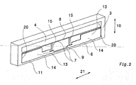
- FIG. 2 lets the panel 3 in a schematic perspective view recognize.
- the panel 3 is preferably formed as a one-piece plastic part and provides a holding element 7 ready, the position-safe recording of in FIG. 2 not shown in detail panel 5 is used. When fully assembled, the holding element 7 grips the control panel 5 like a frame.
- the holding member 7 has a first frame portion 8 and a second frame portion 9.
- the first frame portion 8 may be referred to as the upper frame portion and the second frame portion 9 as the lower frame portion.
- the holding element 7 furthermore has two stops 20, which move with respect to the image plane FIG. 2 left and right sides of the frame sections 8 and 9 are formed. In the final assembled state, these stops 20 serve for lateral support of a control panel 5 received by the retaining element 7 of the panel 3, ie a support of a control panel 5 in the width direction 21.
- a ready-mounted panel 3 is in a schematic side sectional view in FIG. 3 shown.
- the diaphragm 3 has a This provides the recessed grip 4 and provided for receiving the control panel 5 retaining element 7 ready.
- the control panel 5 is inserted into the holding element 7 and it is held by the retaining element 7 in the direction 23 of the front panel 11 form fit. In this case, close the front panel 11 and the front of the panel 5 flush, which in particular the representation after FIG. 3 lets recognize.
- the holding element 7 receives the control panel 5 without gaps. In particular, there are no gaps at the in FIG. 3 Arranged by arrows, ie formed between the control panel 5 and the first frame section 8 on the one hand and the control panel 5 and the second frame section 9 on the other.
- the holding member 7 surrounds the control panel 5 with its frame sections 8 and 9 and with its stops 20 rather accurately, ie without a gap.
- the panel 3 provides wall sections 14. These may be formed partially as spring elements 15.
- the wall sections 14 in turn provide a supporting surface 13, on which the control panel 5 is supported rearwardly in the final assembled state. In a front-side application of force to the control panel 5 is a force-absorbing support of the same through the wall sections 14, whereby a force transmission is ensured in the base body 12 of the panel 3.
- control panel 5 In the height direction 10, the control panel 5 is supported by the first frame section 8 and the second frame section 9.
- the supports 20 provided by the holding element 7 provide support for the control panel 5 in the direction of thickness 23 the wall sections 14 results in particular from the illustration FIG. 3 ,
- the frame sections 8 and 9 ensure that form an undercut with the upper peripheral edge 16 and the lower peripheral edge 17 of the control panel 5 and thus hold the control panel 5 positively, as can be seen in particular from the illustrations after Figures 3 and 4 results.
- control panel 5 has an upper peripheral edge 16 and a lower peripheral edge 17.
- the upper peripheral edge 16 cooperates with the first frame portion 8 of the support member 7 and the lower peripheral edge 17 with the second frame portion 9 of the support member 7 together.
- the two marginal edges 16 and 17 each provide a paragraph 18 or 19 ready.
- the shoulder 18 of the upper peripheral edge 16 in the width direction 21 is preferably wave-shaped, as seen from FIG. 5 seen.
- the first frame section 8 and the second frame section 9 each provide a groove 22 which cooperates with the respective shoulder 18 or 19 of the peripheral edge 16 or 17.
- the paragraph 19 of the lower peripheral edge 17 engages in the corresponding groove 22 of the second frame portion 9, whereby the undercut of the control panel 5 and aperture 3 is formed.
- the first frame section 8 that is, with respect to the drawing plane to FIG. 2
- Upper frame portion 8 of the support member 7 formed elastically deformable. It can be deflected for the purpose of assembly or disassembly in the height direction 10 upwards, that is elastically deformed.
- the frame portion In the deformed position, the frame portion is in its so-called release position, in which the first frame portion 8 and the second frame portion 9 due to the elastic deformation of the first frame portion 8 in the height direction 10 are far apart from each other so that the control panel 5 are inserted into the holding member 7 can.
- the elastic deformation of the first frame portion 8 can then be canceled again, causing a deformation of the first frame portion 8 in the locked position.
- This locking position is in FIG. 3 shown. In this position of the frame section 8, the paragraphs 18 and 19 of the marginal edges 16 and 17 of the control panel 5 in the grooves 22 of the frame sections 8 and 9, whereby the already above-described positive fixing of the control panel 5 relative to the panel 3 is reached.
- spring elements 15 are provided. These are L-shaped in front view and support the first frame section 8 optionally with the interposition of further wall sections 14 relative to the second frame section 9, as can be seen in particular from the illustration FIG. 2 results.
- the first frame section 8 associated paragraph 16 of the peripheral edge 18 of the control panel 5 is wave-shaped, with a trough with a pivot point, d. H. a connection point between frame portion 8 and spring element 15 coincides.
- the above-described embodiment provides the significant advantage that a gap-free arrangement of the control panel 5 is allowed on the panel 3. Incidentally, can be completely dispensed with spring elements in the form of separate components, which simplifies the manufacture and assembly and designed more cost-effective.
Landscapes
- Engineering & Computer Science (AREA)
- Textile Engineering (AREA)
- Casings For Electric Apparatus (AREA)
Priority Applications (2)
| Application Number | Priority Date | Filing Date | Title |
|---|---|---|---|
| PL11401672T PL2607545T3 (pl) | 2011-12-20 | 2011-12-20 | Osłona, zwłaszcza do urządzeń gospodarstwa domowego |
| EP11401672.8A EP2607545B1 (de) | 2011-12-20 | 2011-12-20 | Blende, insbesondere für Haushaltgeräte |
Applications Claiming Priority (1)
| Application Number | Priority Date | Filing Date | Title |
|---|---|---|---|
| EP11401672.8A EP2607545B1 (de) | 2011-12-20 | 2011-12-20 | Blende, insbesondere für Haushaltgeräte |
Publications (2)
| Publication Number | Publication Date |
|---|---|
| EP2607545A1 EP2607545A1 (de) | 2013-06-26 |
| EP2607545B1 true EP2607545B1 (de) | 2014-02-26 |
Family
ID=45497785
Family Applications (1)
| Application Number | Title | Priority Date | Filing Date |
|---|---|---|---|
| EP11401672.8A Active EP2607545B1 (de) | 2011-12-20 | 2011-12-20 | Blende, insbesondere für Haushaltgeräte |
Country Status (2)
| Country | Link |
|---|---|
| EP (1) | EP2607545B1 (pl) |
| PL (1) | PL2607545T3 (pl) |
Family Cites Families (3)
| Publication number | Priority date | Publication date | Assignee | Title |
|---|---|---|---|---|
| DE8332205U1 (de) * | 1983-11-09 | 1986-04-24 | Bosch-Siemens Hausgeräte GmbH, 7000 Stuttgart | Haushaltgerät mit einem Bedienungsfeld |
| DE3413194A1 (de) * | 1984-04-07 | 1985-10-17 | Miele & Cie GmbH & Co, 4830 Gütersloh | Schalterblende |
| KR20050123428A (ko) * | 2004-06-25 | 2005-12-29 | 엘지전자 주식회사 | 컨트롤 패널과 메탈 시트의 결합구조 |
-
2011
- 2011-12-20 PL PL11401672T patent/PL2607545T3/pl unknown
- 2011-12-20 EP EP11401672.8A patent/EP2607545B1/de active Active
Also Published As
| Publication number | Publication date |
|---|---|
| PL2607545T3 (pl) | 2014-06-30 |
| EP2607545A1 (de) | 2013-06-26 |
Similar Documents
| Publication | Publication Date | Title |
|---|---|---|
| EP2611331B1 (de) | Möbelauszugsteil | |
| EP2084339B1 (de) | Abdeckrost | |
| DE102006019959B4 (de) | Tankklappe für Automobile | |
| EP3727093B1 (de) | Schubladenanordnung | |
| EP3535822B1 (de) | Schaltschrank mit einer montageplattenanordnung | |
| EP2704604B1 (de) | Schubkasten | |
| DE202009002972U1 (de) | Längseinsteller mit mindestens einem Endanschlag | |
| DE102017108518B4 (de) | Montageplattenanordnung und ein entsprechendes Verfahren | |
| DE102008049864A1 (de) | Steuerkastenanordnung | |
| DE102009015463A1 (de) | Neigungsverstellvorrichtung für einen Fahrzeugsitz | |
| DE102007057513A1 (de) | Haushaltsgerät, insbesondere Geschirrspülmaschine | |
| DE102013106385B4 (de) | Scharniervorrichtung | |
| DE102016224743A1 (de) | Haushaltsgargerät | |
| DE19510119B4 (de) | Schnellmontage-Befestigungsbeschlag für Schubladen-Frontblenden | |
| DE202011100696U1 (de) | Toleranzausgleichseinrichtung | |
| EP3763908A1 (de) | Vorrichtung zur bewegung eines möbelteils und möbel | |
| DE202009014882U1 (de) | Beschlaggarnitur für zwei Schiebetürflügel | |
| EP3491967A1 (de) | Vorrichtung zum verbinden eines schubelements mit einer führungsschiene, führungssystem und möbel oder haushaltsgerät | |
| DE202015100485U1 (de) | Bausatz für den Einbau eines Positionierungsrahmens in einen Möbelauszug | |
| EP4275550B1 (de) | Anordnung aus einem auflagesteg für einen schubladenboden und einer haltevorrichtung | |
| DE102012104457A1 (de) | Fixierungsanordnung und Schubkasten | |
| EP2607545A1 (de) | Blende, insbesondere für Haushaltgeräte | |
| DE202008004145U1 (de) | Möbelkorpus | |
| EP2484998A2 (de) | Haushaltsgerät | |
| DE102018209343B3 (de) | Kraftfahrzeug |
Legal Events
| Date | Code | Title | Description |
|---|---|---|---|
| AK | Designated contracting states |
Kind code of ref document: A1 Designated state(s): AL AT BE BG CH CY CZ DE DK EE ES FI FR GB GR HR HU IE IS IT LI LT LU LV MC MK MT NL NO PL PT RO RS SE SI SK SM TR |
|
| AX | Request for extension of the european patent |
Extension state: BA ME |
|
| PUAI | Public reference made under article 153(3) epc to a published international application that has entered the european phase |
Free format text: ORIGINAL CODE: 0009012 |
|
| 17P | Request for examination filed |
Effective date: 20130613 |
|
| RBV | Designated contracting states (corrected) |
Designated state(s): AL AT BE BG CH CY CZ DE DK EE ES FI FR GB GR HR HU IE IS IT LI LT LU LV MC MK MT NL NO PL PT RO RS SE SI SK SM TR |
|
| RIC1 | Information provided on ipc code assigned before grant |
Ipc: D06F 39/12 20060101AFI20130827BHEP Ipc: A47L 15/42 20060101ALI20130827BHEP |
|
| GRAP | Despatch of communication of intention to grant a patent |
Free format text: ORIGINAL CODE: EPIDOSNIGR1 |
|
| INTG | Intention to grant announced |
Effective date: 20131009 |
|
| GRAS | Grant fee paid |
Free format text: ORIGINAL CODE: EPIDOSNIGR3 |
|
| GRAA | (expected) grant |
Free format text: ORIGINAL CODE: 0009210 |
|
| AK | Designated contracting states |
Kind code of ref document: B1 Designated state(s): AL AT BE BG CH CY CZ DE DK EE ES FI FR GB GR HR HU IE IS IT LI LT LU LV MC MK MT NL NO PL PT RO RS SE SI SK SM TR |
|
| REG | Reference to a national code |
Ref country code: GB Ref legal event code: FG4D Free format text: NOT ENGLISH |
|
| REG | Reference to a national code |
Ref country code: CH Ref legal event code: EP |
|
| REG | Reference to a national code |
Ref country code: AT Ref legal event code: REF Ref document number: 653683 Country of ref document: AT Kind code of ref document: T Effective date: 20140315 |
|
| REG | Reference to a national code |
Ref country code: IE Ref legal event code: FG4D Free format text: LANGUAGE OF EP DOCUMENT: GERMAN |
|
| REG | Reference to a national code |
Ref country code: DE Ref legal event code: R096 Ref document number: 502011002224 Country of ref document: DE Effective date: 20140417 |
|
| REG | Reference to a national code |
Ref country code: DE Ref legal event code: R084 Ref document number: 502011002224 Country of ref document: DE Effective date: 20140318 |
|
| REG | Reference to a national code |
Ref country code: PL Ref legal event code: LICE Effective date: 20140414 Ref country code: PL Ref legal event code: T3 |
|
| REG | Reference to a national code |
Ref country code: NL Ref legal event code: VDEP Effective date: 20140226 |
|
| REG | Reference to a national code |
Ref country code: LT Ref legal event code: MG4D |
|
| PG25 | Lapsed in a contracting state [announced via postgrant information from national office to epo] |
Ref country code: IS Free format text: LAPSE BECAUSE OF FAILURE TO SUBMIT A TRANSLATION OF THE DESCRIPTION OR TO PAY THE FEE WITHIN THE PRESCRIBED TIME-LIMIT Effective date: 20140626 Ref country code: LT Free format text: LAPSE BECAUSE OF FAILURE TO SUBMIT A TRANSLATION OF THE DESCRIPTION OR TO PAY THE FEE WITHIN THE PRESCRIBED TIME-LIMIT Effective date: 20140226 Ref country code: NO Free format text: LAPSE BECAUSE OF FAILURE TO SUBMIT A TRANSLATION OF THE DESCRIPTION OR TO PAY THE FEE WITHIN THE PRESCRIBED TIME-LIMIT Effective date: 20140526 |
|
| PG25 | Lapsed in a contracting state [announced via postgrant information from national office to epo] |
Ref country code: PT Free format text: LAPSE BECAUSE OF FAILURE TO SUBMIT A TRANSLATION OF THE DESCRIPTION OR TO PAY THE FEE WITHIN THE PRESCRIBED TIME-LIMIT Effective date: 20140626 Ref country code: FI Free format text: LAPSE BECAUSE OF FAILURE TO SUBMIT A TRANSLATION OF THE DESCRIPTION OR TO PAY THE FEE WITHIN THE PRESCRIBED TIME-LIMIT Effective date: 20140226 Ref country code: NL Free format text: LAPSE BECAUSE OF FAILURE TO SUBMIT A TRANSLATION OF THE DESCRIPTION OR TO PAY THE FEE WITHIN THE PRESCRIBED TIME-LIMIT Effective date: 20140226 Ref country code: CY Free format text: LAPSE BECAUSE OF FAILURE TO SUBMIT A TRANSLATION OF THE DESCRIPTION OR TO PAY THE FEE WITHIN THE PRESCRIBED TIME-LIMIT Effective date: 20140226 Ref country code: SE Free format text: LAPSE BECAUSE OF FAILURE TO SUBMIT A TRANSLATION OF THE DESCRIPTION OR TO PAY THE FEE WITHIN THE PRESCRIBED TIME-LIMIT Effective date: 20140226 |
|
| PG25 | Lapsed in a contracting state [announced via postgrant information from national office to epo] |
Ref country code: LV Free format text: LAPSE BECAUSE OF FAILURE TO SUBMIT A TRANSLATION OF THE DESCRIPTION OR TO PAY THE FEE WITHIN THE PRESCRIBED TIME-LIMIT Effective date: 20140226 Ref country code: HR Free format text: LAPSE BECAUSE OF FAILURE TO SUBMIT A TRANSLATION OF THE DESCRIPTION OR TO PAY THE FEE WITHIN THE PRESCRIBED TIME-LIMIT Effective date: 20140226 |
|
| PG25 | Lapsed in a contracting state [announced via postgrant information from national office to epo] |
Ref country code: EE Free format text: LAPSE BECAUSE OF FAILURE TO SUBMIT A TRANSLATION OF THE DESCRIPTION OR TO PAY THE FEE WITHIN THE PRESCRIBED TIME-LIMIT Effective date: 20140226 Ref country code: CZ Free format text: LAPSE BECAUSE OF FAILURE TO SUBMIT A TRANSLATION OF THE DESCRIPTION OR TO PAY THE FEE WITHIN THE PRESCRIBED TIME-LIMIT Effective date: 20140226 Ref country code: DK Free format text: LAPSE BECAUSE OF FAILURE TO SUBMIT A TRANSLATION OF THE DESCRIPTION OR TO PAY THE FEE WITHIN THE PRESCRIBED TIME-LIMIT Effective date: 20140226 Ref country code: RO Free format text: LAPSE BECAUSE OF FAILURE TO SUBMIT A TRANSLATION OF THE DESCRIPTION OR TO PAY THE FEE WITHIN THE PRESCRIBED TIME-LIMIT Effective date: 20140226 |
|
| REG | Reference to a national code |
Ref country code: DE Ref legal event code: R097 Ref document number: 502011002224 Country of ref document: DE |
|
| PG25 | Lapsed in a contracting state [announced via postgrant information from national office to epo] |
Ref country code: ES Free format text: LAPSE BECAUSE OF FAILURE TO SUBMIT A TRANSLATION OF THE DESCRIPTION OR TO PAY THE FEE WITHIN THE PRESCRIBED TIME-LIMIT Effective date: 20140226 Ref country code: SK Free format text: LAPSE BECAUSE OF FAILURE TO SUBMIT A TRANSLATION OF THE DESCRIPTION OR TO PAY THE FEE WITHIN THE PRESCRIBED TIME-LIMIT Effective date: 20140226 |
|
| PLBE | No opposition filed within time limit |
Free format text: ORIGINAL CODE: 0009261 |
|
| STAA | Information on the status of an ep patent application or granted ep patent |
Free format text: STATUS: NO OPPOSITION FILED WITHIN TIME LIMIT |
|
| 26N | No opposition filed |
Effective date: 20141127 |
|
| REG | Reference to a national code |
Ref country code: DE Ref legal event code: R097 Ref document number: 502011002224 Country of ref document: DE Effective date: 20141127 |
|
| PG25 | Lapsed in a contracting state [announced via postgrant information from national office to epo] |
Ref country code: SI Free format text: LAPSE BECAUSE OF FAILURE TO SUBMIT A TRANSLATION OF THE DESCRIPTION OR TO PAY THE FEE WITHIN THE PRESCRIBED TIME-LIMIT Effective date: 20140226 |
|
| PG25 | Lapsed in a contracting state [announced via postgrant information from national office to epo] |
Ref country code: BE Free format text: LAPSE BECAUSE OF NON-PAYMENT OF DUE FEES Effective date: 20141231 |
|
| PG25 | Lapsed in a contracting state [announced via postgrant information from national office to epo] |
Ref country code: LU Free format text: LAPSE BECAUSE OF FAILURE TO SUBMIT A TRANSLATION OF THE DESCRIPTION OR TO PAY THE FEE WITHIN THE PRESCRIBED TIME-LIMIT Effective date: 20141220 |
|
| REG | Reference to a national code |
Ref country code: CH Ref legal event code: PL |
|
| REG | Reference to a national code |
Ref country code: IE Ref legal event code: MM4A |
|
| PG25 | Lapsed in a contracting state [announced via postgrant information from national office to epo] |
Ref country code: IE Free format text: LAPSE BECAUSE OF NON-PAYMENT OF DUE FEES Effective date: 20141220 Ref country code: LI Free format text: LAPSE BECAUSE OF NON-PAYMENT OF DUE FEES Effective date: 20141231 Ref country code: CH Free format text: LAPSE BECAUSE OF NON-PAYMENT OF DUE FEES Effective date: 20141231 |
|
| REG | Reference to a national code |
Ref country code: FR Ref legal event code: PLFP Year of fee payment: 5 |
|
| PG25 | Lapsed in a contracting state [announced via postgrant information from national office to epo] |
Ref country code: SM Free format text: LAPSE BECAUSE OF FAILURE TO SUBMIT A TRANSLATION OF THE DESCRIPTION OR TO PAY THE FEE WITHIN THE PRESCRIBED TIME-LIMIT Effective date: 20140226 |
|
| PG25 | Lapsed in a contracting state [announced via postgrant information from national office to epo] |
Ref country code: MC Free format text: LAPSE BECAUSE OF FAILURE TO SUBMIT A TRANSLATION OF THE DESCRIPTION OR TO PAY THE FEE WITHIN THE PRESCRIBED TIME-LIMIT Effective date: 20140226 |
|
| PG25 | Lapsed in a contracting state [announced via postgrant information from national office to epo] |
Ref country code: BG Free format text: LAPSE BECAUSE OF FAILURE TO SUBMIT A TRANSLATION OF THE DESCRIPTION OR TO PAY THE FEE WITHIN THE PRESCRIBED TIME-LIMIT Effective date: 20140226 Ref country code: RS Free format text: LAPSE BECAUSE OF NON-PAYMENT OF DUE FEES Effective date: 20140226 Ref country code: GR Free format text: LAPSE BECAUSE OF FAILURE TO SUBMIT A TRANSLATION OF THE DESCRIPTION OR TO PAY THE FEE WITHIN THE PRESCRIBED TIME-LIMIT Effective date: 20140527 |
|
| PG25 | Lapsed in a contracting state [announced via postgrant information from national office to epo] |
Ref country code: HU Free format text: LAPSE BECAUSE OF FAILURE TO SUBMIT A TRANSLATION OF THE DESCRIPTION OR TO PAY THE FEE WITHIN THE PRESCRIBED TIME-LIMIT; INVALID AB INITIO Effective date: 20111220 Ref country code: MT Free format text: LAPSE BECAUSE OF FAILURE TO SUBMIT A TRANSLATION OF THE DESCRIPTION OR TO PAY THE FEE WITHIN THE PRESCRIBED TIME-LIMIT Effective date: 20140226 |
|
| GBPC | Gb: european patent ceased through non-payment of renewal fee |
Effective date: 20151220 |
|
| PG25 | Lapsed in a contracting state [announced via postgrant information from national office to epo] |
Ref country code: GB Free format text: LAPSE BECAUSE OF NON-PAYMENT OF DUE FEES Effective date: 20151220 |
|
| REG | Reference to a national code |
Ref country code: FR Ref legal event code: PLFP Year of fee payment: 6 |
|
| REG | Reference to a national code |
Ref country code: FR Ref legal event code: PLFP Year of fee payment: 7 |
|
| REG | Reference to a national code |
Ref country code: AT Ref legal event code: MM01 Ref document number: 653683 Country of ref document: AT Kind code of ref document: T Effective date: 20161220 |
|
| PG25 | Lapsed in a contracting state [announced via postgrant information from national office to epo] |
Ref country code: AT Free format text: LAPSE BECAUSE OF NON-PAYMENT OF DUE FEES Effective date: 20161220 |
|
| PG25 | Lapsed in a contracting state [announced via postgrant information from national office to epo] |
Ref country code: MK Free format text: LAPSE BECAUSE OF FAILURE TO SUBMIT A TRANSLATION OF THE DESCRIPTION OR TO PAY THE FEE WITHIN THE PRESCRIBED TIME-LIMIT Effective date: 20140226 |
|
| PG25 | Lapsed in a contracting state [announced via postgrant information from national office to epo] |
Ref country code: AL Free format text: LAPSE BECAUSE OF FAILURE TO SUBMIT A TRANSLATION OF THE DESCRIPTION OR TO PAY THE FEE WITHIN THE PRESCRIBED TIME-LIMIT Effective date: 20140226 |
|
| PGFP | Annual fee paid to national office [announced via postgrant information from national office to epo] |
Ref country code: PL Payment date: 20221110 Year of fee payment: 12 |
|
| PGFP | Annual fee paid to national office [announced via postgrant information from national office to epo] |
Ref country code: IT Payment date: 20221222 Year of fee payment: 12 |
|
| P01 | Opt-out of the competence of the unified patent court (upc) registered |
Effective date: 20230529 |
|
| PG25 | Lapsed in a contracting state [announced via postgrant information from national office to epo] |
Ref country code: PL Free format text: LAPSE BECAUSE OF NON-PAYMENT OF DUE FEES Effective date: 20231220 |
|
| PG25 | Lapsed in a contracting state [announced via postgrant information from national office to epo] |
Ref country code: IT Free format text: LAPSE BECAUSE OF NON-PAYMENT OF DUE FEES Effective date: 20231220 |
|
| PGFP | Annual fee paid to national office [announced via postgrant information from national office to epo] |
Ref country code: FR Payment date: 20251230 Year of fee payment: 15 |
|
| PGFP | Annual fee paid to national office [announced via postgrant information from national office to epo] |
Ref country code: TR Payment date: 20251209 Year of fee payment: 15 |
|
| PGFP | Annual fee paid to national office [announced via postgrant information from national office to epo] |
Ref country code: DE Payment date: 20251231 Year of fee payment: 15 |