EP2607019B1 - Polierkissen für ein poliersystem - Google Patents
Polierkissen für ein poliersystem Download PDFInfo
- Publication number
- EP2607019B1 EP2607019B1 EP11818418.3A EP11818418A EP2607019B1 EP 2607019 B1 EP2607019 B1 EP 2607019B1 EP 11818418 A EP11818418 A EP 11818418A EP 2607019 B1 EP2607019 B1 EP 2607019B1
- Authority
- EP
- European Patent Office
- Prior art keywords
- polishing
- region
- polishing pad
- supplier
- channels
- Prior art date
- Legal status (The legal status is an assumption and is not a legal conclusion. Google has not performed a legal analysis and makes no representation as to the accuracy of the status listed.)
- Active
Links
Images




Classifications
-
- B—PERFORMING OPERATIONS; TRANSPORTING
- B24—GRINDING; POLISHING
- B24B—MACHINES, DEVICES, OR PROCESSES FOR GRINDING OR POLISHING; DRESSING OR CONDITIONING OF ABRADING SURFACES; FEEDING OF GRINDING, POLISHING, OR LAPPING AGENTS
- B24B37/00—Lapping machines or devices; Accessories
- B24B37/11—Lapping tools
- B24B37/20—Lapping pads for working plane surfaces
- B24B37/26—Lapping pads for working plane surfaces characterised by the shape of the lapping pad surface, e.g. grooved
Definitions
- the present disclosure relates to a polishing pad, and more particularly, to a polishing pad of a polishing system for polishing a sheet glass used for a liquid crystal display.
- a sheet glass or, a glass pane
- the sheet glass is prepared by a fusion method or a float method. Most existing sheet glasses (about 95% or more) are prepared by the float method.
- a glass produced by the float method (or, a float glass) is processed into a ribbon shape in a float bath and then cut into a predetermined size during a cutting process.
- a polishing process for removing fine unevenness or impurities present at the surface of the float glasses is performed.
- the polishing process of a glass substrate may be classified into a so-called 'Oscar' method where individual glass substrates are polished one by one and a so-called 'inline' method where a series of glass substrates are polished successively.
- the conventional polishing process may also be classified into a 'single surface polishing' where only one surface of a glass substrate is polished and a 'both surface polishing' where both surfaces of a glass substrate are polished.
- the conventional sheet glass polishing device polishes a sheet glass by using a polishing liquid supplied onto the polishing plate while rotating a lower unit, in a state where the sheet glass is located on the lower unit (or, the lower plate) and a polishing pad of the polishing plate (or, an upper plate) is in contact with the sheet glass.
- the polishing pad for polishing the sheet glass in contact with a surface of the sheet glass to be polished is attached to the polishing plate of the sheet glass polishing device.
- FIG. 1 is a plane view schematically showing a conventional polishing pad.
- a conventional polishing pad 1 has an overall disk shape and includes a central supply hole 2 prepared at the center thereof and six radial supply holes 3 arranged radially at a predetermined radius.
- the supply holes 2 and 3 are used for receiving a polishing liquid from the outside toward a polishing surface of the polishing pad 1.
- a channel for regularly dispersing a polishing liquid, supplied from the polishing liquid supply holes 2 and 3, to the entire polishing surface is provided at the polishing surface of the polishing pad 1.
- This channel has a channel pattern with a straight form (a rectangular lattice).
- the polishing pad 1 rotates (in the clockwise direction or in the counterclockwise direction) in contact with a sheet glass (not shown), the polishing liquid flowing through the channel formed at the polishing surface of the polishing pad 1 is influenced by a centrifugal force. Therefore, in the conventional polishing pad 1, the rotating direction of the polishing pad 1 is not in agreement with the direction of the straight lattice-type channel pattern of the polishing surface. This causes a flux difference or irregular flow of the polishing liquid which flows through the channel formed at the polishing pad 1. Meanwhile, in case of the polishing pad 1 having such a channel pattern, if a polishing rate is high or an amount of supplied polishing liquid is great, a hydroplaning phenomenon may occur during the polishing process.
- FIG. 2 is a graph showing a measured speed distribution of a polishing liquid which flows through the channel of the conventional polishing pad of FIG. 1 .
- the X axis of the graph represents an arbitrary location of the polishing pad 1, which means a direction expressed by the Roman alphabet
- the Y axis represents a flow rate (kg/m 2 s) of the polishing liquid.
- a speed deviation of the polishing liquid generated from the entire polishing surface of the polishing pad 1 is 0.6 m/s, which is very great. In other words, the flux difference of the polishing liquid is remarkable near the edge of the polishing pad 1.
- JP 2001 071256 discloses a polishing pad according to the preamble of claim 1.
- the present disclosure is designed to solve the problems of the prior art, and therefore it is an object of the present disclosure to provide a polishing pad of a polishing system with an improved structure, which may uniformly distribute a polishing liquid over the entire polishing surface by optimizing a channel pattern formed at the polishing pad.
- the present disclosure provides a polishing pad of a polishing system according to the claim 1, which is mountable to a polishing plate and has a predetermined channel pattern so as to allow a polishing liquid supplied from a polishing liquid supplier to move on a polishing surface.
- the polishing pattern may include: a first channel pattern formed in a first region containing the center of the polishing pad; and a second channel pattern formed in a second region divided to surround the first region from the center toward the outside.
- the first channel pattern may be a conventional straight lattice pattern or not.
- the second channel pattern is more influenced by a centrifugal force of the polishing pad, the second channel pattern is preferably configured with a non-straight form (for example, a radial form, a curved form, a secondary curve or the like), and its direction may be identical to or opposite to the rotating direction of the polishing pad, as understood by those skilled in the art.
- the second channel pattern may include: at least two circular channels concentrically arranged from the center and spaced apart from each other by a predetermined interval; and a plurality of radial channels arranged extending radially from the center to intersect the circular channels.
- each radial channel may be provided to be in agreement with a centrifugal direction of the polishing pad.
- each radial channel is preferably disposed in a straight form, but as an alternative, the radial channels may have a non-straight form in order to give an effect corresponding to the centrifugal force of the polishing pad, as apparent to those skilled in the art.
- the second region may include an inner region disposed adjacent to the first region and an outer region disposed at an outer side of the inner region, and, in the second channel pattern, channels of the outer region may be disposed more densely than channels of the inner region.
- channels of the inner region may be disposed more densely than channels of the outer region.
- the second channel pattern may further include a second radial channel formed between neighboring radial channels in the outer region.
- the second radial channel is used to arrange the channels more densely and may be configured with a curved shape, without being a straight shape, as apparent to those skilled in the art.
- the polishing pad may be circular.
- the polishing pad preferably has a disk shape whose diameter is about 200 mm.
- the first channel pattern may include a plurality of lattice-type channels substantially orthogonal to each other.
- the channel may have a width of about 1 to 30 mm, and an interval between neighboring channels may be about 10 to 100 mm.
- the polishing pad is used for polishing a float glass prepared by means of a float method.
- the polishing pad may also be applied to a sheet glass prepared by means of a fusion method or other parts which need precise polishing to maintain predetermined flatness, as apparent to those skilled in the art.
- the polishing pad of a polishing system may minimize a flux difference or deviation of a polishing liquid flowing through channels of a polishing surface by forming so-called radial channels having a radial pattern in a direction substantially in agreement with the direction of a centrifugal force caused by the rotation of the polishing pad based on the center of the polishing surface. Therefore, during the polishing process of the polishing system, polishing uniformity and wide process range may be ensured.
- FIG. 3 is a schematic view showing a sheet glass polishing system to which a polishing pad according to a preferred embodiment of the present disclosure may be installed.
- a sheet glass polishing system 100 is used for polishing a sheet glass so that the flatness of a large sheet glass G having, for example, a size over 1000 mm and a thickness of about 0.3 mm to 1.1 mm may be maintained to a level required for a liquid crystal display.
- the polishing system 100 includes, for example, a lower unit 110 having a turn table 112 capable of rotating a sheet glass G to be polished with a predetermined rotating number in a state where the sheet glass G is fixed; an upper unit 120 installed at the upper side of the lower unit 110 and movable in a horizontal direction and a vertical direction so that a polishing pad 200 contactable to the upper surface, namely a surface to be polished, of the sheet glass G supported by the lower unit 110 is attached thereto, and a polishing liquid supply unit 130 for supplying a polishing liquid between the polishing surface of the polishing pad 200 and a surface of the sheet glass G to be polished.
- a lower unit 110 having a turn table 112 capable of rotating a sheet glass G to be polished with a predetermined rotating number in a state where the sheet glass G is fixed
- an upper unit 120 installed at the upper side of the lower unit 110 and movable in a horizontal direction and a vertical direction so that a polishing pad 200 contactable to the upper surface, namely a surface
- a dimension of a rectangular sheet glass G to be polished (the smallest dimension between a length and a width) is greater than dimensions of the upper unit 120 and/or the polishing pad 200 attached thereto.
- a rotary shaft 114 of the lower unit 110 and a spindle of the upper unit 120 are not located on the same straight line but preferably relatively move in an offset state.
- the entire surface of the sheet glass G to be polished is uniformly polished by, for example, a polishing liquid supplied from the polishing liquid supply unit 130 while the upper unit 120 is rotated by the rotation of the lower unit 110.
- Reference symbol 140 represents a carrier for supporting the sheet glass G to the lower unit 110.
- the upper unit 120 and the polishing liquid supply unit 130 may employ an upper unit and a polishing liquid supply unit disclosed in Korean Patent Application Nos. 10-2009-192290 , 10-2009-192292 and 10-2009-192293, filed on March 6, 2009 by the same applicant as this application and entitled 'a sheet glass polishing system', and an upper unit disclosed in Korean Patent Application No. 10-2010-0007100, filed on January 19, 2010 by the same applicant as this application and entitled "a lower unit for a 'sheet glass polishing system and a polishing method using the same' , as well understood by those skilled in the art.
- the sheet glass G of this embodiment is prepared by means of a float method and refers to a so-called float glass obtained by cutting a ribbon-type glass, processed into predetermined thickness and width in a float bath, by a predetermined length.
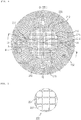
- FIG. 4 is a plane view showing a polishing pad according to a preferred embodiment of the present disclosure
- FIG. 5 is an enlarged view showing the portion "A" of FIG. 4
- FIG. 6 is an enlarged view showing the portion "B" of FIG. 4
- FIG. 7 is a cross-sectional view taken along the line 7-7 of FIG. 4 .
- the polishing pad 200 has a polishing surface 202 installed at the lower end of the upper unit 120 of the polishing system 100 of FIG. 3 and contactable with the sheet glass G, and the polishing pad 200 has a disk structure whose diameter is about 200 mm.
- the polishing pad 200 has two kinds of predetermined channel patterns, namely a first channel pattern 220 and a second channel pattern 230, so that a polishing liquid supplied from a polishing liquid supplier 210 formed through the polishing pad 200 may move on the polishing surface 202.
- each channel 201 has a width W of about 1 to 30 mm, and an interval D between neighboring channels 201 is about 10 to 100 mm.
- the polishing pad 200 includes a first region 204 containing the center C and a second region 206 divided to surround the first region.
- the first channel pattern 220 is formed in the first region 204
- the second channel pattern 230 is formed in the second region 206.
- the second region 206 includes an inner region 205 disposed adjacent to the first region 204 and an outer region 207 extending from the outer side of the inner region 205 to the outermost side of the polishing pad 200.
- the first channel pattern 220 has a conventional straight lattice pattern.
- the first channel pattern 220 is formed so that the channels 201 are substantially orthogonal to each other, similar to the conventional polishing pad 1.
- the second channel pattern 230 includes a plurality of circular channels 232 concentrically arranged from the center C and spaced apart from each other by a predetermined interval and a plurality of radial channels 234 extending radially from the center C to intersect the circular channels 232.
- Each radial channel 234 is provided to be in agreement with a centrifugal direction of the polishing pad 200 and is disposed in a straight form.
- the radial channel 234 may also be configured with a non-straight form, as apparent to those skilled in the art.
- the pattern of channels formed in the outer region 207 is denser than the pattern of channels formed in the inner region 205.
- channels of the inner region 205 may be disposed more densely than channels of the outer region.
- the second channel pattern 230 further includes a second radial channel 236 formed between neighboring radial channels 234 in the outer region 207.
- the second radial channel 236 allows the radial channels 234 to be arranged more densely.
- the second radial channel 236 may have a curved form, without being limited to a straight form.
- the second channel pattern 230 is more influenced by a centrifugal force of the polishing pad 200
- the second channel pattern 230 is preferably configured with a non-straight form (for example, a radial form, a curved form, a secondary curve or the like), and its direction may be identical to or opposite to the rotating direction of the polishing pad 200.
- the polishing liquid supplier 210 provided at the polishing pad 200 includes a first supplier 212 for supplying a polishing liquid to the first region 204 and a second supplier 214 for supplying a polishing liquid to the second region 206.
- the polishing liquid supplier 210 preferably has a width of 10 to 20 mm.
- the first supplier 212 includes a first hole 213 formed through the polishing pad 200 to be in agreement with the center C and a straight supply path 215 disposed across the first region 204 to communicate with the first hole 213 and the second supplier 214 on the polishing surface.
- the second supplier 214 includes a plurality of second holes formed through the second supplier 214 on a border line of the first region 204 and the second region 206, a circular supply path 217 provided on the border line to communicate with the second holes and a curved radial supply path 219 formed to curve outwards with a radial shape from each second hole.
- the circular supply path 217 also plays a role of separating and dividing the first region 204 and the second region 206 from each other. For this, the width of the circular supply path 217 may be greater than widths of other suppliers 210.
- the polishing pad 200 configured as above may reduce the flow or flux deviation of the polishing liquid since the radial channel pattern is formed in a direction identical to the direction of the centrifugal force generated by the rotation of the polishing pad 200.
- FIG. 8 is a graph showing a measurement result of a flow rate deviation of a polishing liquid, which is measured at the polishing pad according to a preferred embodiment of the present disclosure, shown in FIG. 4 .
- the X axis of the graph represents an arbitrary location of the polishing pad 200, which means a direction expressed by the Roman alphabet in FIG. 8
- the Y axis represents a flow rate (kg/m 2 s) of the polishing liquid.
- the deviation of a flow rate is small over the entire area thereof.
- the range of a speed deviation of a polishing liquid was 0.1 m/s to 0.6 m/s in a case where a conventional polishing pad was used, if the polishing pad 200 according to the present disclosure is used, the range of a speed deviation is 0.15 m/s to 0.4 m/s, which is reduced than the conventional one.
- the speed deviation of the polishing liquid is reduced, an unnecessary hydroplaning phenomenon may be prevented, and the polishing flatness of the sheet glass G may be ensured.
- the polishing work may be uniformly performed near the edge of the polishing pad 200, a wide processing range is ensured.
Landscapes
- Engineering & Computer Science (AREA)
- Mechanical Engineering (AREA)
- Finish Polishing, Edge Sharpening, And Grinding By Specific Grinding Devices (AREA)
- Surface Treatment Of Glass (AREA)
Claims (9)
- Polierkissen eines Poliersystems, das an eine Polierplatte montierbar ist und ein vorbestimmtes Kanalmuster aufweist, um einer Polierflüssigkeit, die von einer Zufuhr für Polierflüssigkeit zugeführt wird, zu ermöglichen, sich auf eine Polieroberfläche zu bewegen,
wobei das Kanalmuster zumindest zwei Arten von Mustern aufweist,
wobei die Zufuhr für Polierflüssigkeit eine erste Zuführung (212) zum Liefern der Polierflüssigkeit in einen ersten Bereich (204) und eine zweite Zuführung (214) zum Liefern der Polierflüssigkeit in einen zweiten Bereich (206) einschließt,
wobei die erste Zuführung (212) einen geraden Zufuhrweg (215) einschließt, der über den ersten Bereich angeordnet ist, um mit dem ersten Loch zu kommunizieren, dadurch gekennzeichnet, dass die erste Zuführung (212) ein erstes Loch einschließt, das durch die erste Zuführung (212) geformt ist, um mit der Mitte (C) des Polierkissens übereinzustimmen, und der gerade Zufuhrweg (215) über dem ersten Bereich angeordnet ist, um mit dem ersten Loch und der zweiten Zuführung (214) zu kommunizieren, und
wobei die zweite Zuführung (214) eine Vielzahl von zweiten Löchern (215) einschließt, die durch die zweite Zuführung (214) hindurch an einer Grenzlinie des ersten Bereichs (204) und des zweiten Bereichs (206) geformt sind, wobei ein kreisförmiger Zufuhrweg (217) an der Grenzlinie bereitgestellt ist, um mit den zweiten Löchern (215) und einem gekrümmten, radialen Zufuhrweg (219) zu kommunizieren, der geformt ist, sich nach außen gerichtet mit einer radialen Form ab jedem zweiten Loch zu krümmen. - Polierkissen eines Poliersystems nach Anspruch 1, wobei das Poliermuster einschließt:Ein erstes Kanalmuster (220), das im ersten Bereich (204) geformt ist, der die Mitte des Polierkissens enthält; undein zweites Kanalmuster (230), das im zweiten Bereich (206) geformt ist, das unterteilt ist, den ersten Bereich (204) von der Mitte in Richtung der Außenseite zu umgeben.
- Polierkissen eines Poliersystems nach Anspruch 2, wobei das zweite Kanalmuster (230) einschließt:Zumindest zwei kreisförmige Kanäle (232), die konzentrisch ab der Mitte (C) angeordnet und um ein vorbestimmtes Intervall voneinander beabstandet sind; undeine Vielzahl radialer Kanäle (234), die sich radial ab der Mitte (C) erstrecken, um die kreisförmigen Kanäle (232) zu schneiden.
- Polierkissen eines Poliersystems nach Anspruch 3, wobei jeder radiale Kanal bereitgestellt ist, in Übereinstimmung mit einer zentrifugalen Richtung des Polierkissens zu sein.
- Polierkissen eines Poliersystems nach Anspruch 2,
wobei der zweite Bereich (206) einen inneren Bereich (205), der angrenzend an den ersten Bereich (204) angeordnet ist und einen äußeren Bereich (207) einschließt, der an einer Außenseite des inneren Bereichs (205) angeordnet ist, und
wobei, im zweiten Kanalmuster (230), Kanäle des äußeren Bereichs (207) dichter als Kanäle im inneren Bereich (205) angeordnet sind. - Polierkissen eines Poliersystems nach Anspruch 5, wobei das zweite Kanalmuster (230) ferner einen zweiten radialen Kanal (236) einschließt, der zwischen benachbarten radialen Kanälen (234) im äußeren Bereich (207) geformt ist.
- Polierkissen eines Poliersystems nach Anspruch 1, wobei das Polierkissen kreisförmig ist.
- Polierkissen eines Poliersystems nach Anspruch 2, wobei das erste Kanalmuster (220) eine Vielzahl von gitterartigen Kanälen einschließt, die im Wesentlichen orthogonal zueinander sind.
- Polierkissen eines Poliersystems nach Anspruch 1, wobei der Kanal eine Breite von ca. 1 bis 30 mm aufweist, und ein Intervall zwischen benachbarten Kanälen ca. 10 bis 100 mm beträgt.
Applications Claiming Priority (2)
| Application Number | Priority Date | Filing Date | Title |
|---|---|---|---|
| KR1020100079882A KR101232787B1 (ko) | 2010-08-18 | 2010-08-18 | 연마 시스템용 연마 패드 |
| PCT/KR2011/006088 WO2012023818A2 (ko) | 2010-08-18 | 2011-08-18 | 연마 시스템용 연마 패드 |
Publications (3)
| Publication Number | Publication Date |
|---|---|
| EP2607019A2 EP2607019A2 (de) | 2013-06-26 |
| EP2607019A4 EP2607019A4 (de) | 2017-08-16 |
| EP2607019B1 true EP2607019B1 (de) | 2020-01-08 |
Family
ID=45605574
Family Applications (1)
| Application Number | Title | Priority Date | Filing Date |
|---|---|---|---|
| EP11818418.3A Active EP2607019B1 (de) | 2010-08-18 | 2011-08-18 | Polierkissen für ein poliersystem |
Country Status (6)
| Country | Link |
|---|---|
| US (1) | US8647178B2 (de) |
| EP (1) | EP2607019B1 (de) |
| JP (1) | JP5924596B2 (de) |
| KR (1) | KR101232787B1 (de) |
| CN (1) | CN103079767B (de) |
| WO (1) | WO2012023818A2 (de) |
Families Citing this family (16)
| Publication number | Priority date | Publication date | Assignee | Title |
|---|---|---|---|---|
| CN103317430B (zh) * | 2013-05-22 | 2015-08-19 | 浙江工业大学 | 防碰撞悬浮抛光装置 |
| CN105881246B (zh) * | 2014-12-19 | 2018-06-08 | 浙江金徕镀膜有限公司 | 基板处理装置 |
| JP2017001111A (ja) * | 2015-06-05 | 2017-01-05 | 株式会社ディスコ | 研磨パッド及びcmp研磨方法 |
| US10875146B2 (en) * | 2016-03-24 | 2020-12-29 | Rohm And Haas Electronic Materials Cmp Holdings | Debris-removal groove for CMP polishing pad |
| CN106392820B (zh) * | 2016-09-27 | 2019-05-17 | 中国科学院上海光学精密机械研究所 | 一种环形抛光机 |
| US10586708B2 (en) | 2017-06-14 | 2020-03-10 | Rohm And Haas Electronic Materials Cmp Holdings, Inc. | Uniform CMP polishing method |
| US10861702B2 (en) | 2017-06-14 | 2020-12-08 | Rohm And Haas Electronic Materials Cmp Holdings | Controlled residence CMP polishing method |
| US10857647B2 (en) | 2017-06-14 | 2020-12-08 | Rohm And Haas Electronic Materials Cmp Holdings | High-rate CMP polishing method |
| US10777418B2 (en) * | 2017-06-14 | 2020-09-15 | Rohm And Haas Electronic Materials Cmp Holdings, I | Biased pulse CMP groove pattern |
| US10857648B2 (en) * | 2017-06-14 | 2020-12-08 | Rohm And Haas Electronic Materials Cmp Holdings | Trapezoidal CMP groove pattern |
| CN108747721B (zh) * | 2018-05-29 | 2019-11-01 | 江苏锡沂高新区科技发展有限公司 | 一种半导体晶圆半精磨、精磨设备 |
| KR102256204B1 (ko) * | 2018-06-29 | 2021-05-26 | 주식회사 엘지화학 | 유리기판 연마 패드 |
| KR102656242B1 (ko) * | 2019-04-16 | 2024-04-09 | 주식회사 엘지화학 | 화학기계연마용 연마패드 |
| US12186855B2 (en) * | 2019-06-19 | 2025-01-07 | Kuraray Co., Ltd. | Polishing pad, method for manufacturing polishing pad, and polishing method |
| CN110722467A (zh) * | 2019-09-27 | 2020-01-24 | 台山市远鹏研磨科技有限公司 | 一种圆盘形抛光皮 |
| CN116061085A (zh) * | 2023-02-13 | 2023-05-05 | 上海芯谦集成电路有限公司 | 一种利于散热的抛光垫 |
Family Cites Families (23)
| Publication number | Priority date | Publication date | Assignee | Title |
|---|---|---|---|---|
| US5020283A (en) * | 1990-01-22 | 1991-06-04 | Micron Technology, Inc. | Polishing pad with uniform abrasion |
| JPH10329012A (ja) * | 1997-03-21 | 1998-12-15 | Canon Inc | 研磨装置および研磨方法 |
| JPH11216663A (ja) * | 1998-02-03 | 1999-08-10 | Sony Corp | 研磨パッド、研磨装置および研磨方法 |
| JP3821947B2 (ja) * | 1998-03-31 | 2006-09-13 | 信越半導体株式会社 | ウェーハ研磨装置及びウェーハ研磨方法 |
| GB2345255B (en) * | 1998-12-29 | 2000-12-27 | United Microelectronics Corp | Chemical-Mechanical Polishing Pad |
| JP2001071256A (ja) * | 1999-08-31 | 2001-03-21 | Shinozaki Seisakusho:Kk | 研磨パッドの溝形成方法及び装置並びに研磨パッド |
| KR100325614B1 (ko) * | 1999-10-25 | 2002-02-25 | 황인길 | 화학 기계적 연마용 연마 패드 |
| JP2003145402A (ja) | 2001-11-09 | 2003-05-20 | Nippon Electric Glass Co Ltd | ガラス物品用研磨具 |
| JP4478859B2 (ja) | 2003-04-23 | 2010-06-09 | ニッタ・ハース株式会社 | 研磨パッド |
| US6783436B1 (en) * | 2003-04-29 | 2004-08-31 | Rohm And Haas Electronic Materials Cmp Holdings, Inc. | Polishing pad with optimized grooves and method of forming same |
| JP2005177897A (ja) * | 2003-12-17 | 2005-07-07 | Nec Electronics Corp | 研磨方法および研磨装置と半導体装置製造方法 |
| US6955587B2 (en) * | 2004-01-30 | 2005-10-18 | Rohm And Haas Electronic Materials Cmp Holdings, Inc | Grooved polishing pad and method |
| US7329174B2 (en) * | 2004-05-20 | 2008-02-12 | Jsr Corporation | Method of manufacturing chemical mechanical polishing pad |
| KR100568258B1 (ko) | 2004-07-01 | 2006-04-07 | 삼성전자주식회사 | 화학적 기계적 연마용 연마 패드 및 이를 이용하는 화학적기계적 연마 장치 |
| JP2006068870A (ja) * | 2004-09-03 | 2006-03-16 | Hoya Corp | 磁気ディスク用ガラス基板の製造方法、磁気ディスクの製造方法及び研磨布 |
| US7131895B2 (en) * | 2005-01-13 | 2006-11-07 | Rohm And Haas Electronic Materials Cmp Holdings, Inc. | CMP pad having a radially alternating groove segment configuration |
| CN100526017C (zh) * | 2005-09-16 | 2009-08-12 | 联华电子股份有限公司 | 化学机械研磨装置及其研磨垫的调节方法 |
| KR20070070094A (ko) * | 2005-12-28 | 2007-07-03 | 제이에스알 가부시끼가이샤 | 화학 기계 연마 패드 및 화학 기계 연마 방법 |
| JP2007201449A (ja) * | 2005-12-28 | 2007-08-09 | Jsr Corp | 化学機械研磨パッドおよび化学機械研磨方法 |
| US7311590B1 (en) | 2007-01-31 | 2007-12-25 | Rohm And Haas Electronic Materials Cmp Holdings, Inc. | Polishing pad with grooves to retain slurry on the pad texture |
| JP5093650B2 (ja) * | 2007-06-07 | 2012-12-12 | 株式会社ニコン | 研磨装置及び研磨方法 |
| KR100987213B1 (ko) | 2008-07-11 | 2010-10-12 | 삼성전자주식회사 | 바이오 키를 이용하여 VoIP을 기반으로 한 통신을수행하는 방법 및 장치 |
| CN201287300Y (zh) * | 2008-10-30 | 2009-08-12 | 贝达先进材料股份有限公司 | 抛光垫 |
-
2010
- 2010-08-18 KR KR1020100079882A patent/KR101232787B1/ko active Active
-
2011
- 2011-08-18 CN CN201180039962.2A patent/CN103079767B/zh active Active
- 2011-08-18 EP EP11818418.3A patent/EP2607019B1/de active Active
- 2011-08-18 WO PCT/KR2011/006088 patent/WO2012023818A2/ko not_active Ceased
- 2011-08-18 JP JP2013524796A patent/JP5924596B2/ja active Active
-
2013
- 2013-02-15 US US13/769,029 patent/US8647178B2/en active Active
Non-Patent Citations (1)
| Title |
|---|
| None * |
Also Published As
| Publication number | Publication date |
|---|---|
| EP2607019A4 (de) | 2017-08-16 |
| WO2012023818A2 (ko) | 2012-02-23 |
| US20130196580A1 (en) | 2013-08-01 |
| KR20120017280A (ko) | 2012-02-28 |
| JP5924596B2 (ja) | 2016-05-25 |
| JP2013535350A (ja) | 2013-09-12 |
| US8647178B2 (en) | 2014-02-11 |
| CN103079767A (zh) | 2013-05-01 |
| CN103079767B (zh) | 2016-01-20 |
| WO2012023818A3 (ko) | 2012-05-10 |
| EP2607019A2 (de) | 2013-06-26 |
| KR101232787B1 (ko) | 2013-02-13 |
Similar Documents
| Publication | Publication Date | Title |
|---|---|---|
| US8647178B2 (en) | Polishing pad of polishing system | |
| KR101394947B1 (ko) | 취성재료용 스크라이빙 휠, 및 이를 이용한 스크라이브 방법, 스크라이브 장치 및 스크라이브 공구 | |
| KR20110022563A (ko) | 양두 연삭 장치 및 웨이퍼의 제조 방법 | |
| WO2011126028A1 (ja) | ガラス板の製造方法及び製造装置 | |
| JP2025019299A (ja) | 炭化珪素単結晶インゴットの切断方法、炭化珪素単結晶基板の製造方法及び炭化珪素単結晶基板 | |
| WO2017163565A1 (ja) | 研磨材 | |
| KR101273729B1 (ko) | 판상체의 연마 방법 및 그 장치 | |
| US20190321932A1 (en) | Quartz glass member with increased exposed area, method for manufacturing same, and blade with multiple peripheral cutting edges | |
| CN109454548B (zh) | 两面研磨装置用的被研磨物保持用游星轮 | |
| TWI566289B (zh) | Tray and workpiece double-sided grinding device | |
| EP3573783A1 (de) | Verfahren und vorrichtung zur endbearbeitung von kanten von glasscheiben | |
| JP2014229910A (ja) | ウエハーまたは平板ガラス露光装置のステッパーチャック | |
| US20200376628A1 (en) | Grinding material | |
| CN213561898U (zh) | 研磨垫及研磨系统 | |
| JP4992306B2 (ja) | ワークキャリアとその製造方法及び両面研磨機 | |
| JP3224896U (ja) | 研磨パッド | |
| KR101455919B1 (ko) | 웨이퍼 양면 연마 장치의 정반 구조 | |
| KR102481107B1 (ko) | 복수의 연마헤드를 이용한 유리기판 연마방법 | |
| WO2018008551A1 (ja) | 研磨材 | |
| KR20200006386A (ko) | 와이어 쏘우 정렬 유닛과 그를 구비한 와이어 쏘잉 장치 및 그를 이용한 정렬 방법 | |
| JP2005177954A (ja) | 半導体基板の形成装置 | |
| JPH08174541A (ja) | ドレッサ及びドレッシング方法 |
Legal Events
| Date | Code | Title | Description |
|---|---|---|---|
| PUAI | Public reference made under article 153(3) epc to a published international application that has entered the european phase |
Free format text: ORIGINAL CODE: 0009012 |
|
| 17P | Request for examination filed |
Effective date: 20130129 |
|
| AK | Designated contracting states |
Kind code of ref document: A2 Designated state(s): AL AT BE BG CH CY CZ DE DK EE ES FI FR GB GR HR HU IE IS IT LI LT LU LV MC MK MT NL NO PL PT RO RS SE SI SK SM TR |
|
| RIN1 | Information on inventor provided before grant (corrected) |
Inventor name: SONG, JAE-IK Inventor name: IM, YE-HOON Inventor name: LEE, DAE-YEON Inventor name: PARK, SU-CHAN Inventor name: MIN, KYOUNG-HOON |
|
| DAX | Request for extension of the european patent (deleted) | ||
| REG | Reference to a national code |
Ref country code: DE Ref legal event code: R079 Ref document number: 602011064538 Country of ref document: DE Free format text: PREVIOUS MAIN CLASS: B24D0011000000 Ipc: B24B0037260000 |
|
| A4 | Supplementary search report drawn up and despatched |
Effective date: 20170719 |
|
| RIC1 | Information provided on ipc code assigned before grant |
Ipc: B24B 37/26 20120101AFI20170713BHEP |
|
| RAP1 | Party data changed (applicant data changed or rights of an application transferred) |
Owner name: LG CHEM, LTD. |
|
| GRAP | Despatch of communication of intention to grant a patent |
Free format text: ORIGINAL CODE: EPIDOSNIGR1 |
|
| STAA | Information on the status of an ep patent application or granted ep patent |
Free format text: STATUS: GRANT OF PATENT IS INTENDED |
|
| INTG | Intention to grant announced |
Effective date: 20191004 |
|
| GRAS | Grant fee paid |
Free format text: ORIGINAL CODE: EPIDOSNIGR3 |
|
| GRAA | (expected) grant |
Free format text: ORIGINAL CODE: 0009210 |
|
| STAA | Information on the status of an ep patent application or granted ep patent |
Free format text: STATUS: THE PATENT HAS BEEN GRANTED |
|
| AK | Designated contracting states |
Kind code of ref document: B1 Designated state(s): AL AT BE BG CH CY CZ DE DK EE ES FI FR GB GR HR HU IE IS IT LI LT LU LV MC MK MT NL NO PL PT RO RS SE SI SK SM TR |
|
| REG | Reference to a national code |
Ref country code: GB Ref legal event code: FG4D |
|
| REG | Reference to a national code |
Ref country code: CH Ref legal event code: EP |
|
| REG | Reference to a national code |
Ref country code: DE Ref legal event code: R096 Ref document number: 602011064538 Country of ref document: DE |
|
| REG | Reference to a national code |
Ref country code: IE Ref legal event code: FG4D |
|
| REG | Reference to a national code |
Ref country code: AT Ref legal event code: REF Ref document number: 1222102 Country of ref document: AT Kind code of ref document: T Effective date: 20200215 |
|
| REG | Reference to a national code |
Ref country code: NL Ref legal event code: MP Effective date: 20200108 |
|
| REG | Reference to a national code |
Ref country code: LT Ref legal event code: MG4D |
|
| PG25 | Lapsed in a contracting state [announced via postgrant information from national office to epo] |
Ref country code: NO Free format text: LAPSE BECAUSE OF FAILURE TO SUBMIT A TRANSLATION OF THE DESCRIPTION OR TO PAY THE FEE WITHIN THE PRESCRIBED TIME-LIMIT Effective date: 20200408 Ref country code: NL Free format text: LAPSE BECAUSE OF FAILURE TO SUBMIT A TRANSLATION OF THE DESCRIPTION OR TO PAY THE FEE WITHIN THE PRESCRIBED TIME-LIMIT Effective date: 20200108 Ref country code: LT Free format text: LAPSE BECAUSE OF FAILURE TO SUBMIT A TRANSLATION OF THE DESCRIPTION OR TO PAY THE FEE WITHIN THE PRESCRIBED TIME-LIMIT Effective date: 20200108 Ref country code: PT Free format text: LAPSE BECAUSE OF FAILURE TO SUBMIT A TRANSLATION OF THE DESCRIPTION OR TO PAY THE FEE WITHIN THE PRESCRIBED TIME-LIMIT Effective date: 20200531 Ref country code: RS Free format text: LAPSE BECAUSE OF FAILURE TO SUBMIT A TRANSLATION OF THE DESCRIPTION OR TO PAY THE FEE WITHIN THE PRESCRIBED TIME-LIMIT Effective date: 20200108 Ref country code: FI Free format text: LAPSE BECAUSE OF FAILURE TO SUBMIT A TRANSLATION OF THE DESCRIPTION OR TO PAY THE FEE WITHIN THE PRESCRIBED TIME-LIMIT Effective date: 20200108 |
|
| PG25 | Lapsed in a contracting state [announced via postgrant information from national office to epo] |
Ref country code: HR Free format text: LAPSE BECAUSE OF FAILURE TO SUBMIT A TRANSLATION OF THE DESCRIPTION OR TO PAY THE FEE WITHIN THE PRESCRIBED TIME-LIMIT Effective date: 20200108 Ref country code: GR Free format text: LAPSE BECAUSE OF FAILURE TO SUBMIT A TRANSLATION OF THE DESCRIPTION OR TO PAY THE FEE WITHIN THE PRESCRIBED TIME-LIMIT Effective date: 20200409 Ref country code: SE Free format text: LAPSE BECAUSE OF FAILURE TO SUBMIT A TRANSLATION OF THE DESCRIPTION OR TO PAY THE FEE WITHIN THE PRESCRIBED TIME-LIMIT Effective date: 20200108 Ref country code: LV Free format text: LAPSE BECAUSE OF FAILURE TO SUBMIT A TRANSLATION OF THE DESCRIPTION OR TO PAY THE FEE WITHIN THE PRESCRIBED TIME-LIMIT Effective date: 20200108 Ref country code: IS Free format text: LAPSE BECAUSE OF FAILURE TO SUBMIT A TRANSLATION OF THE DESCRIPTION OR TO PAY THE FEE WITHIN THE PRESCRIBED TIME-LIMIT Effective date: 20200508 Ref country code: BG Free format text: LAPSE BECAUSE OF FAILURE TO SUBMIT A TRANSLATION OF THE DESCRIPTION OR TO PAY THE FEE WITHIN THE PRESCRIBED TIME-LIMIT Effective date: 20200408 |
|
| REG | Reference to a national code |
Ref country code: DE Ref legal event code: R097 Ref document number: 602011064538 Country of ref document: DE |
|
| PG25 | Lapsed in a contracting state [announced via postgrant information from national office to epo] |
Ref country code: CZ Free format text: LAPSE BECAUSE OF FAILURE TO SUBMIT A TRANSLATION OF THE DESCRIPTION OR TO PAY THE FEE WITHIN THE PRESCRIBED TIME-LIMIT Effective date: 20200108 Ref country code: ES Free format text: LAPSE BECAUSE OF FAILURE TO SUBMIT A TRANSLATION OF THE DESCRIPTION OR TO PAY THE FEE WITHIN THE PRESCRIBED TIME-LIMIT Effective date: 20200108 Ref country code: RO Free format text: LAPSE BECAUSE OF FAILURE TO SUBMIT A TRANSLATION OF THE DESCRIPTION OR TO PAY THE FEE WITHIN THE PRESCRIBED TIME-LIMIT Effective date: 20200108 Ref country code: EE Free format text: LAPSE BECAUSE OF FAILURE TO SUBMIT A TRANSLATION OF THE DESCRIPTION OR TO PAY THE FEE WITHIN THE PRESCRIBED TIME-LIMIT Effective date: 20200108 Ref country code: SM Free format text: LAPSE BECAUSE OF FAILURE TO SUBMIT A TRANSLATION OF THE DESCRIPTION OR TO PAY THE FEE WITHIN THE PRESCRIBED TIME-LIMIT Effective date: 20200108 Ref country code: DK Free format text: LAPSE BECAUSE OF FAILURE TO SUBMIT A TRANSLATION OF THE DESCRIPTION OR TO PAY THE FEE WITHIN THE PRESCRIBED TIME-LIMIT Effective date: 20200108 Ref country code: SK Free format text: LAPSE BECAUSE OF FAILURE TO SUBMIT A TRANSLATION OF THE DESCRIPTION OR TO PAY THE FEE WITHIN THE PRESCRIBED TIME-LIMIT Effective date: 20200108 |
|
| PLBE | No opposition filed within time limit |
Free format text: ORIGINAL CODE: 0009261 |
|
| STAA | Information on the status of an ep patent application or granted ep patent |
Free format text: STATUS: NO OPPOSITION FILED WITHIN TIME LIMIT |
|
| REG | Reference to a national code |
Ref country code: AT Ref legal event code: MK05 Ref document number: 1222102 Country of ref document: AT Kind code of ref document: T Effective date: 20200108 |
|
| 26N | No opposition filed |
Effective date: 20201009 |
|
| PG25 | Lapsed in a contracting state [announced via postgrant information from national office to epo] |
Ref country code: IT Free format text: LAPSE BECAUSE OF FAILURE TO SUBMIT A TRANSLATION OF THE DESCRIPTION OR TO PAY THE FEE WITHIN THE PRESCRIBED TIME-LIMIT Effective date: 20200108 Ref country code: AT Free format text: LAPSE BECAUSE OF FAILURE TO SUBMIT A TRANSLATION OF THE DESCRIPTION OR TO PAY THE FEE WITHIN THE PRESCRIBED TIME-LIMIT Effective date: 20200108 |
|
| PG25 | Lapsed in a contracting state [announced via postgrant information from national office to epo] |
Ref country code: PL Free format text: LAPSE BECAUSE OF FAILURE TO SUBMIT A TRANSLATION OF THE DESCRIPTION OR TO PAY THE FEE WITHIN THE PRESCRIBED TIME-LIMIT Effective date: 20200108 Ref country code: SI Free format text: LAPSE BECAUSE OF FAILURE TO SUBMIT A TRANSLATION OF THE DESCRIPTION OR TO PAY THE FEE WITHIN THE PRESCRIBED TIME-LIMIT Effective date: 20200108 |
|
| PG25 | Lapsed in a contracting state [announced via postgrant information from national office to epo] |
Ref country code: MC Free format text: LAPSE BECAUSE OF FAILURE TO SUBMIT A TRANSLATION OF THE DESCRIPTION OR TO PAY THE FEE WITHIN THE PRESCRIBED TIME-LIMIT Effective date: 20200108 |
|
| REG | Reference to a national code |
Ref country code: CH Ref legal event code: PL |
|
| PG25 | Lapsed in a contracting state [announced via postgrant information from national office to epo] |
Ref country code: CH Free format text: LAPSE BECAUSE OF NON-PAYMENT OF DUE FEES Effective date: 20200831 Ref country code: LI Free format text: LAPSE BECAUSE OF NON-PAYMENT OF DUE FEES Effective date: 20200831 Ref country code: LU Free format text: LAPSE BECAUSE OF NON-PAYMENT OF DUE FEES Effective date: 20200818 |
|
| REG | Reference to a national code |
Ref country code: BE Ref legal event code: MM Effective date: 20200831 |
|
| PG25 | Lapsed in a contracting state [announced via postgrant information from national office to epo] |
Ref country code: BE Free format text: LAPSE BECAUSE OF NON-PAYMENT OF DUE FEES Effective date: 20200831 Ref country code: IE Free format text: LAPSE BECAUSE OF NON-PAYMENT OF DUE FEES Effective date: 20200818 |
|
| PG25 | Lapsed in a contracting state [announced via postgrant information from national office to epo] |
Ref country code: TR Free format text: LAPSE BECAUSE OF FAILURE TO SUBMIT A TRANSLATION OF THE DESCRIPTION OR TO PAY THE FEE WITHIN THE PRESCRIBED TIME-LIMIT Effective date: 20200108 Ref country code: MT Free format text: LAPSE BECAUSE OF FAILURE TO SUBMIT A TRANSLATION OF THE DESCRIPTION OR TO PAY THE FEE WITHIN THE PRESCRIBED TIME-LIMIT Effective date: 20200108 Ref country code: CY Free format text: LAPSE BECAUSE OF FAILURE TO SUBMIT A TRANSLATION OF THE DESCRIPTION OR TO PAY THE FEE WITHIN THE PRESCRIBED TIME-LIMIT Effective date: 20200108 |
|
| PG25 | Lapsed in a contracting state [announced via postgrant information from national office to epo] |
Ref country code: MK Free format text: LAPSE BECAUSE OF FAILURE TO SUBMIT A TRANSLATION OF THE DESCRIPTION OR TO PAY THE FEE WITHIN THE PRESCRIBED TIME-LIMIT Effective date: 20200108 Ref country code: AL Free format text: LAPSE BECAUSE OF FAILURE TO SUBMIT A TRANSLATION OF THE DESCRIPTION OR TO PAY THE FEE WITHIN THE PRESCRIBED TIME-LIMIT Effective date: 20200108 |
|
| PGFP | Annual fee paid to national office [announced via postgrant information from national office to epo] |
Ref country code: DE Payment date: 20250721 Year of fee payment: 15 |
|
| PGFP | Annual fee paid to national office [announced via postgrant information from national office to epo] |
Ref country code: GB Payment date: 20250722 Year of fee payment: 15 |
|
| PGFP | Annual fee paid to national office [announced via postgrant information from national office to epo] |
Ref country code: FR Payment date: 20250725 Year of fee payment: 15 |