EP2605694B1 - Verfahren für den nachweis von amyloidproteinen - Google Patents
Verfahren für den nachweis von amyloidproteinen Download PDFInfo
- Publication number
- EP2605694B1 EP2605694B1 EP11745903.2A EP11745903A EP2605694B1 EP 2605694 B1 EP2605694 B1 EP 2605694B1 EP 11745903 A EP11745903 A EP 11745903A EP 2605694 B1 EP2605694 B1 EP 2605694B1
- Authority
- EP
- European Patent Office
- Prior art keywords
- amyloid
- eye
- fluorescence
- binding compound
- compound
- Prior art date
- Legal status (The legal status is an assumption and is not a legal conclusion. Google has not performed a legal analysis and makes no representation as to the accuracy of the status listed.)
- Active
Links
- 102000009091 Amyloidogenic Proteins Human genes 0.000 title claims description 122
- 108010048112 Amyloidogenic Proteins Proteins 0.000 title claims description 122
- 238000000034 method Methods 0.000 title claims description 72
- 150000001875 compounds Chemical class 0.000 claims description 162
- 230000003942 amyloidogenic effect Effects 0.000 claims description 26
- 238000000295 emission spectrum Methods 0.000 claims description 25
- 238000000695 excitation spectrum Methods 0.000 claims description 22
- 238000009826 distribution Methods 0.000 claims description 17
- 241000124008 Mammalia Species 0.000 claims description 14
- 230000010287 polarization Effects 0.000 claims description 10
- NIXOWILDQLNWCW-UHFFFAOYSA-M Acrylate Chemical compound [O-]C(=O)C=C NIXOWILDQLNWCW-UHFFFAOYSA-M 0.000 claims description 4
- 210000000695 crystalline len Anatomy 0.000 description 80
- NRZNTGUFHSJBTD-HKOYGPOVSA-N 2-[2-(2-methoxyethoxy)ethoxy]ethyl (e)-2-cyano-3-(6-piperidin-1-ylnaphthalen-2-yl)prop-2-enoate Chemical compound C1=CC2=CC(/C=C(C(=O)OCCOCCOCCOC)\C#N)=CC=C2C=C1N1CCCCC1 NRZNTGUFHSJBTD-HKOYGPOVSA-N 0.000 description 59
- 230000003287 optical effect Effects 0.000 description 47
- 238000005259 measurement Methods 0.000 description 42
- 208000037265 diseases, disorders, signs and symptoms Diseases 0.000 description 35
- 208000035475 disorder Diseases 0.000 description 27
- 238000001514 detection method Methods 0.000 description 26
- 208000024827 Alzheimer disease Diseases 0.000 description 23
- 210000003484 anatomy Anatomy 0.000 description 23
- 108090000765 processed proteins & peptides Proteins 0.000 description 20
- 241001465754 Metazoa Species 0.000 description 18
- 241000283973 Oryctolagus cuniculus Species 0.000 description 18
- 239000000523 sample Substances 0.000 description 18
- 238000005070 sampling Methods 0.000 description 17
- 230000005284 excitation Effects 0.000 description 16
- 210000001519 tissue Anatomy 0.000 description 16
- 230000006870 function Effects 0.000 description 15
- 238000005286 illumination Methods 0.000 description 12
- 108010090849 Amyloid beta-Peptides Proteins 0.000 description 11
- 102000013455 Amyloid beta-Peptides Human genes 0.000 description 11
- 210000004087 cornea Anatomy 0.000 description 11
- 102000004169 proteins and genes Human genes 0.000 description 11
- 108090000623 proteins and genes Proteins 0.000 description 11
- 239000002775 capsule Substances 0.000 description 10
- 238000002474 experimental method Methods 0.000 description 10
- 229910052594 sapphire Inorganic materials 0.000 description 10
- 239000010980 sapphire Substances 0.000 description 10
- 108010064539 amyloid beta-protein (1-42) Proteins 0.000 description 9
- 210000001742 aqueous humor Anatomy 0.000 description 9
- AZOPGDOIOXKJRA-UHFFFAOYSA-L chembl1817788 Chemical compound [Na+].[Na+].C1=C(C([O-])=O)C(O)=CC=C1N=NC1=CC=C(C=2C=CC(=CC=2)N=NC=2C=C(C(O)=CC=2)C([O-])=O)C=C1 AZOPGDOIOXKJRA-UHFFFAOYSA-L 0.000 description 9
- -1 e.g. Proteins 0.000 description 9
- 238000013519 translation Methods 0.000 description 9
- 238000004422 calculation algorithm Methods 0.000 description 8
- 201000010099 disease Diseases 0.000 description 8
- 239000007850 fluorescent dye Substances 0.000 description 8
- 210000004940 nucleus Anatomy 0.000 description 8
- 239000002674 ointment Substances 0.000 description 8
- 238000012360 testing method Methods 0.000 description 8
- 101710137189 Amyloid-beta A4 protein Proteins 0.000 description 7
- 101710151993 Amyloid-beta precursor protein Proteins 0.000 description 7
- 102100022704 Amyloid-beta precursor protein Human genes 0.000 description 7
- DZHSAHHDTRWUTF-SIQRNXPUSA-N amyloid-beta polypeptide 42 Chemical compound C([C@@H](C(=O)N[C@@H](C)C(=O)N[C@@H](CCC(O)=O)C(=O)N[C@@H](CC(O)=O)C(=O)N[C@H](C(=O)NCC(=O)N[C@@H](CO)C(=O)N[C@@H](CC(N)=O)C(=O)N[C@@H](CCCCN)C(=O)NCC(=O)N[C@@H](C)C(=O)N[C@H](C(=O)N[C@@H]([C@@H](C)CC)C(=O)NCC(=O)N[C@@H](CC(C)C)C(=O)N[C@@H](CCSC)C(=O)N[C@@H](C(C)C)C(=O)NCC(=O)NCC(=O)N[C@@H](C(C)C)C(=O)N[C@@H](C(C)C)C(=O)N[C@@H]([C@@H](C)CC)C(=O)N[C@@H](C)C(O)=O)[C@@H](C)CC)C(C)C)NC(=O)[C@H](CC=1C=CC=CC=1)NC(=O)[C@@H](NC(=O)[C@H](CC(C)C)NC(=O)[C@H](CCCCN)NC(=O)[C@H](CCC(N)=O)NC(=O)[C@H](CC=1N=CNC=1)NC(=O)[C@H](CC=1N=CNC=1)NC(=O)[C@@H](NC(=O)[C@H](CCC(O)=O)NC(=O)[C@H](CC=1C=CC(O)=CC=1)NC(=O)CNC(=O)[C@H](CO)NC(=O)[C@H](CC(O)=O)NC(=O)[C@H](CC=1N=CNC=1)NC(=O)[C@H](CCCNC(N)=N)NC(=O)[C@H](CC=1C=CC=CC=1)NC(=O)[C@H](CCC(O)=O)NC(=O)[C@H](C)NC(=O)[C@@H](N)CC(O)=O)C(C)C)C(C)C)C1=CC=CC=C1 DZHSAHHDTRWUTF-SIQRNXPUSA-N 0.000 description 7
- 238000010586 diagram Methods 0.000 description 7
- 238000000338 in vitro Methods 0.000 description 7
- 102000004196 processed proteins & peptides Human genes 0.000 description 7
- 102000014824 Crystallins Human genes 0.000 description 6
- 108010064003 Crystallins Proteins 0.000 description 6
- 230000008859 change Effects 0.000 description 6
- 230000001360 synchronised effect Effects 0.000 description 6
- 208000010859 Creutzfeldt-Jakob disease Diseases 0.000 description 5
- 238000004364 calculation method Methods 0.000 description 5
- IQFVPQOLBLOTPF-HKXUKFGYSA-L congo red Chemical compound [Na+].[Na+].C1=CC=CC2=C(N)C(/N=N/C3=CC=C(C=C3)C3=CC=C(C=C3)/N=N/C3=C(C4=CC=CC=C4C(=C3)S([O-])(=O)=O)N)=CC(S([O-])(=O)=O)=C21 IQFVPQOLBLOTPF-HKXUKFGYSA-L 0.000 description 5
- 238000003745 diagnosis Methods 0.000 description 5
- 239000003885 eye ointment Substances 0.000 description 5
- 229940069265 ophthalmic ointment Drugs 0.000 description 5
- 230000004845 protein aggregation Effects 0.000 description 5
- JADVWWSKYZXRGX-UHFFFAOYSA-M thioflavine T Chemical compound [Cl-].C1=CC(N(C)C)=CC=C1C1=[N+](C)C2=CC=C(C)C=C2S1 JADVWWSKYZXRGX-UHFFFAOYSA-M 0.000 description 5
- 208000002177 Cataract Diseases 0.000 description 4
- 201000011240 Frontotemporal dementia Diseases 0.000 description 4
- XFFSCOOTVXBLCK-QAVVBOBSSA-N OC(=O)c1cc(ccc1O)\N=N\c1ccc(cc1)-c1ccc(cc1)\N=N\c1ccc(O)c(c1)C(O)=O Chemical compound OC(=O)c1cc(ccc1O)\N=N\c1ccc(cc1)-c1ccc(cc1)\N=N\c1ccc(O)c(c1)C(O)=O XFFSCOOTVXBLCK-QAVVBOBSSA-N 0.000 description 4
- 208000024777 Prion disease Diseases 0.000 description 4
- 238000001727 in vivo Methods 0.000 description 4
- 230000003252 repetitive effect Effects 0.000 description 4
- 239000000243 solution Substances 0.000 description 4
- 230000002123 temporal effect Effects 0.000 description 4
- 208000018756 Variant Creutzfeldt-Jakob disease Diseases 0.000 description 3
- 230000015572 biosynthetic process Effects 0.000 description 3
- 208000005881 bovine spongiform encephalopathy Diseases 0.000 description 3
- 210000004556 brain Anatomy 0.000 description 3
- 239000003795 chemical substances by application Substances 0.000 description 3
- 238000002405 diagnostic procedure Methods 0.000 description 3
- 230000004069 differentiation Effects 0.000 description 3
- 238000001857 fluorescence decay curve Methods 0.000 description 3
- 238000004519 manufacturing process Methods 0.000 description 3
- 230000007246 mechanism Effects 0.000 description 3
- 230000015654 memory Effects 0.000 description 3
- 239000002245 particle Substances 0.000 description 3
- 238000002360 preparation method Methods 0.000 description 3
- 230000008569 process Effects 0.000 description 3
- 241000894007 species Species 0.000 description 3
- 238000004611 spectroscopical analysis Methods 0.000 description 3
- 238000011200 topical administration Methods 0.000 description 3
- 238000012935 Averaging Methods 0.000 description 2
- 241000283690 Bos taurus Species 0.000 description 2
- 241000282465 Canis Species 0.000 description 2
- 206010007748 Cataract cortical Diseases 0.000 description 2
- 206010012289 Dementia Diseases 0.000 description 2
- 201000010374 Down Syndrome Diseases 0.000 description 2
- 241000282324 Felis Species 0.000 description 2
- 201000002832 Lewy body dementia Diseases 0.000 description 2
- 208000018737 Parkinson disease Diseases 0.000 description 2
- 208000027089 Parkinsonian disease Diseases 0.000 description 2
- 206010034010 Parkinsonism Diseases 0.000 description 2
- 208000000609 Pick Disease of the Brain Diseases 0.000 description 2
- 241000288906 Primates Species 0.000 description 2
- 102000029797 Prion Human genes 0.000 description 2
- 108091000054 Prion Proteins 0.000 description 2
- 206010044688 Trisomy 21 Diseases 0.000 description 2
- 230000002776 aggregation Effects 0.000 description 2
- 238000004220 aggregation Methods 0.000 description 2
- 102000013640 alpha-Crystallin B Chain Human genes 0.000 description 2
- 108010051585 alpha-Crystallin B Chain Proteins 0.000 description 2
- 230000006933 amyloid-beta aggregation Effects 0.000 description 2
- 206010002026 amyotrophic lateral sclerosis Diseases 0.000 description 2
- 239000011230 binding agent Substances 0.000 description 2
- 208000017580 chronic wasting disease Diseases 0.000 description 2
- 238000004590 computer program Methods 0.000 description 2
- 208000029511 cortical cataract Diseases 0.000 description 2
- 230000001054 cortical effect Effects 0.000 description 2
- 230000001086 cytosolic effect Effects 0.000 description 2
- 238000006073 displacement reaction Methods 0.000 description 2
- 238000009510 drug design Methods 0.000 description 2
- 239000000835 fiber Substances 0.000 description 2
- 238000002189 fluorescence spectrum Methods 0.000 description 2
- 239000012216 imaging agent Substances 0.000 description 2
- 230000001939 inductive effect Effects 0.000 description 2
- 230000003834 intracellular effect Effects 0.000 description 2
- 238000011835 investigation Methods 0.000 description 2
- 230000001404 mediated effect Effects 0.000 description 2
- BDAGIHXWWSANSR-UHFFFAOYSA-N methanoic acid Natural products OC=O BDAGIHXWWSANSR-UHFFFAOYSA-N 0.000 description 2
- 125000000956 methoxy group Chemical group [H]C([H])([H])O* 0.000 description 2
- 230000004770 neurodegeneration Effects 0.000 description 2
- 238000012634 optical imaging Methods 0.000 description 2
- 238000012545 processing Methods 0.000 description 2
- 208000008864 scrapie Diseases 0.000 description 2
- 230000035945 sensitivity Effects 0.000 description 2
- 238000003860 storage Methods 0.000 description 2
- 239000000126 substance Substances 0.000 description 2
- 230000000699 topical effect Effects 0.000 description 2
- OSWFIVFLDKOXQC-UHFFFAOYSA-N 4-(3-methoxyphenyl)aniline Chemical compound COC1=CC=CC(C=2C=CC(N)=CC=2)=C1 OSWFIVFLDKOXQC-UHFFFAOYSA-N 0.000 description 1
- 208000023434 Alpers-Huttenlocher syndrome Diseases 0.000 description 1
- 208000037259 Amyloid Plaque Diseases 0.000 description 1
- 208000011990 Corticobasal Degeneration Diseases 0.000 description 1
- 206010067889 Dementia with Lewy bodies Diseases 0.000 description 1
- 208000004986 Diffuse Cerebral Sclerosis of Schilder Diseases 0.000 description 1
- 241000282412 Homo Species 0.000 description 1
- 208000023105 Huntington disease Diseases 0.000 description 1
- YQEZLKZALYSWHR-UHFFFAOYSA-N Ketamine Chemical compound C=1C=CC=C(Cl)C=1C1(NC)CCCCC1=O YQEZLKZALYSWHR-UHFFFAOYSA-N 0.000 description 1
- 208000009829 Lewy Body Disease Diseases 0.000 description 1
- 102000010750 Metalloproteins Human genes 0.000 description 1
- 108010063312 Metalloproteins Proteins 0.000 description 1
- 208000001089 Multiple system atrophy Diseases 0.000 description 1
- 241000699670 Mus sp. Species 0.000 description 1
- 206010029306 Neurological signs and symptoms Diseases 0.000 description 1
- 239000004264 Petrolatum Substances 0.000 description 1
- 208000032023 Signs and Symptoms Diseases 0.000 description 1
- 101710172711 Structural protein Proteins 0.000 description 1
- 208000032859 Synucleinopathies Diseases 0.000 description 1
- 208000034799 Tauopathies Diseases 0.000 description 1
- 230000032683 aging Effects 0.000 description 1
- 108010064397 amyloid beta-protein (1-40) Proteins 0.000 description 1
- 238000004458 analytical method Methods 0.000 description 1
- 238000003491 array Methods 0.000 description 1
- 230000004397 blinking Effects 0.000 description 1
- 210000005013 brain tissue Anatomy 0.000 description 1
- 210000004027 cell Anatomy 0.000 description 1
- 238000012512 characterization method Methods 0.000 description 1
- 230000009920 chelation Effects 0.000 description 1
- 238000006243 chemical reaction Methods 0.000 description 1
- 238000003776 cleavage reaction Methods 0.000 description 1
- 239000003086 colorant Substances 0.000 description 1
- 238000004891 communication Methods 0.000 description 1
- 230000001186 cumulative effect Effects 0.000 description 1
- 210000000172 cytosol Anatomy 0.000 description 1
- 238000007405 data analysis Methods 0.000 description 1
- 230000001419 dependent effect Effects 0.000 description 1
- 230000008021 deposition Effects 0.000 description 1
- 229940006919 dexdomitor Drugs 0.000 description 1
- VPNGEIHDPSLNMU-MERQFXBCSA-N dexmedetomidine hydrochloride Chemical compound Cl.C1([C@@H](C)C=2C(=C(C)C=CC=2)C)=CNC=N1 VPNGEIHDPSLNMU-MERQFXBCSA-N 0.000 description 1
- 230000010339 dilation Effects 0.000 description 1
- 239000000539 dimer Substances 0.000 description 1
- 231100000673 dose–response relationship Toxicity 0.000 description 1
- 239000000975 dye Substances 0.000 description 1
- 238000005516 engineering process Methods 0.000 description 1
- 238000013401 experimental design Methods 0.000 description 1
- 210000000744 eyelid Anatomy 0.000 description 1
- 201000006061 fatal familial insomnia Diseases 0.000 description 1
- 238000000799 fluorescence microscopy Methods 0.000 description 1
- 235000019253 formic acid Nutrition 0.000 description 1
- 239000012634 fragment Substances 0.000 description 1
- 208000010544 human prion disease Diseases 0.000 description 1
- 238000002347 injection Methods 0.000 description 1
- 239000007924 injection Substances 0.000 description 1
- 230000003993 interaction Effects 0.000 description 1
- 229960003299 ketamine Drugs 0.000 description 1
- 206010023497 kuru Diseases 0.000 description 1
- 210000003644 lens cell Anatomy 0.000 description 1
- 239000003446 ligand Substances 0.000 description 1
- 239000007788 liquid Substances 0.000 description 1
- 239000003550 marker Substances 0.000 description 1
- 239000002184 metal Substances 0.000 description 1
- 229910052751 metal Inorganic materials 0.000 description 1
- UZKWTJUDCOPSNM-UHFFFAOYSA-N methoxybenzene Substances CCCCOC=C UZKWTJUDCOPSNM-UHFFFAOYSA-N 0.000 description 1
- 239000002480 mineral oil Substances 0.000 description 1
- 235000010446 mineral oil Nutrition 0.000 description 1
- 201000011540 mitochondrial DNA depletion syndrome 4a Diseases 0.000 description 1
- 239000003068 molecular probe Substances 0.000 description 1
- 230000002969 morbid Effects 0.000 description 1
- 201000007601 neurodegeneration with brain iron accumulation Diseases 0.000 description 1
- 208000015122 neurodegenerative disease Diseases 0.000 description 1
- 230000000626 neurodegenerative effect Effects 0.000 description 1
- 208000021629 neuronal intranuclear inclusion disease Diseases 0.000 description 1
- 239000002773 nucleotide Substances 0.000 description 1
- 125000003729 nucleotide group Chemical group 0.000 description 1
- 208000002593 pantothenate kinase-associated neurodegeneration Diseases 0.000 description 1
- 230000001717 pathogenic effect Effects 0.000 description 1
- 230000001575 pathological effect Effects 0.000 description 1
- 230000007310 pathophysiology Effects 0.000 description 1
- 229940066842 petrolatum Drugs 0.000 description 1
- 235000019271 petrolatum Nutrition 0.000 description 1
- 230000003389 potentiating effect Effects 0.000 description 1
- 230000003244 pro-oxidative effect Effects 0.000 description 1
- 201000002212 progressive supranuclear palsy Diseases 0.000 description 1
- 230000006337 proteolytic cleavage Effects 0.000 description 1
- NGVDGCNFYWLIFO-UHFFFAOYSA-N pyridoxal 5'-phosphate Chemical class CC1=NC=C(COP(O)(O)=O)C(C=O)=C1O NGVDGCNFYWLIFO-UHFFFAOYSA-N 0.000 description 1
- 239000003642 reactive oxygen metabolite Substances 0.000 description 1
- 239000001044 red dye Substances 0.000 description 1
- 238000006479 redox reaction Methods 0.000 description 1
- 230000007017 scission Effects 0.000 description 1
- 239000004065 semiconductor Substances 0.000 description 1
- 238000000926 separation method Methods 0.000 description 1
- 239000007787 solid Substances 0.000 description 1
- 230000003595 spectral effect Effects 0.000 description 1
- 238000007619 statistical method Methods 0.000 description 1
- 239000011550 stock solution Substances 0.000 description 1
- 238000010254 subcutaneous injection Methods 0.000 description 1
- 239000007929 subcutaneous injection Substances 0.000 description 1
- 208000011580 syndromic disease Diseases 0.000 description 1
- 239000013638 trimer Substances 0.000 description 1
- 230000000007 visual effect Effects 0.000 description 1
Images


Classifications
-
- A—HUMAN NECESSITIES
- A61—MEDICAL OR VETERINARY SCIENCE; HYGIENE
- A61B—DIAGNOSIS; SURGERY; IDENTIFICATION
- A61B5/00—Measuring for diagnostic purposes; Identification of persons
- A61B5/145—Measuring characteristics of blood in vivo, e.g. gas concentration, pH value; Measuring characteristics of body fluids or tissues, e.g. interstitial fluid, cerebral tissue
- A61B5/14546—Measuring characteristics of blood in vivo, e.g. gas concentration, pH value; Measuring characteristics of body fluids or tissues, e.g. interstitial fluid, cerebral tissue for measuring analytes not otherwise provided for, e.g. ions, cytochromes
-
- A—HUMAN NECESSITIES
- A61—MEDICAL OR VETERINARY SCIENCE; HYGIENE
- A61B—DIAGNOSIS; SURGERY; IDENTIFICATION
- A61B3/00—Apparatus for testing the eyes; Instruments for examining the eyes
-
- A—HUMAN NECESSITIES
- A61—MEDICAL OR VETERINARY SCIENCE; HYGIENE
- A61B—DIAGNOSIS; SURGERY; IDENTIFICATION
- A61B3/00—Apparatus for testing the eyes; Instruments for examining the eyes
- A61B3/0008—Apparatus for testing the eyes; Instruments for examining the eyes provided with illuminating means
-
- A—HUMAN NECESSITIES
- A61—MEDICAL OR VETERINARY SCIENCE; HYGIENE
- A61B—DIAGNOSIS; SURGERY; IDENTIFICATION
- A61B3/00—Apparatus for testing the eyes; Instruments for examining the eyes
- A61B3/10—Objective types, i.e. instruments for examining the eyes independent of the patients' perceptions or reactions
- A61B3/1005—Objective types, i.e. instruments for examining the eyes independent of the patients' perceptions or reactions for measuring distances inside the eye, e.g. thickness of the cornea
-
- A—HUMAN NECESSITIES
- A61—MEDICAL OR VETERINARY SCIENCE; HYGIENE
- A61B—DIAGNOSIS; SURGERY; IDENTIFICATION
- A61B3/00—Apparatus for testing the eyes; Instruments for examining the eyes
- A61B3/10—Objective types, i.e. instruments for examining the eyes independent of the patients' perceptions or reactions
- A61B3/107—Objective types, i.e. instruments for examining the eyes independent of the patients' perceptions or reactions for determining the shape or measuring the curvature of the cornea
-
- A—HUMAN NECESSITIES
- A61—MEDICAL OR VETERINARY SCIENCE; HYGIENE
- A61B—DIAGNOSIS; SURGERY; IDENTIFICATION
- A61B3/00—Apparatus for testing the eyes; Instruments for examining the eyes
- A61B3/10—Objective types, i.e. instruments for examining the eyes independent of the patients' perceptions or reactions
- A61B3/11—Objective types, i.e. instruments for examining the eyes independent of the patients' perceptions or reactions for measuring interpupillary distance or diameter of pupils
- A61B3/111—Objective types, i.e. instruments for examining the eyes independent of the patients' perceptions or reactions for measuring interpupillary distance or diameter of pupils for measuring interpupillary distance
-
- A—HUMAN NECESSITIES
- A61—MEDICAL OR VETERINARY SCIENCE; HYGIENE
- A61B—DIAGNOSIS; SURGERY; IDENTIFICATION
- A61B3/00—Apparatus for testing the eyes; Instruments for examining the eyes
- A61B3/10—Objective types, i.e. instruments for examining the eyes independent of the patients' perceptions or reactions
- A61B3/117—Objective types, i.e. instruments for examining the eyes independent of the patients' perceptions or reactions for examining the anterior chamber or the anterior chamber angle, e.g. gonioscopes
- A61B3/1173—Objective types, i.e. instruments for examining the eyes independent of the patients' perceptions or reactions for examining the anterior chamber or the anterior chamber angle, e.g. gonioscopes for examining the eye lens
-
- A—HUMAN NECESSITIES
- A61—MEDICAL OR VETERINARY SCIENCE; HYGIENE
- A61B—DIAGNOSIS; SURGERY; IDENTIFICATION
- A61B5/00—Measuring for diagnostic purposes; Identification of persons
-
- A—HUMAN NECESSITIES
- A61—MEDICAL OR VETERINARY SCIENCE; HYGIENE
- A61B—DIAGNOSIS; SURGERY; IDENTIFICATION
- A61B5/00—Measuring for diagnostic purposes; Identification of persons
- A61B5/0059—Measuring for diagnostic purposes; Identification of persons using light, e.g. diagnosis by transillumination, diascopy, fluorescence
- A61B5/0062—Arrangements for scanning
- A61B5/0068—Confocal scanning
-
- A—HUMAN NECESSITIES
- A61—MEDICAL OR VETERINARY SCIENCE; HYGIENE
- A61B—DIAGNOSIS; SURGERY; IDENTIFICATION
- A61B5/00—Measuring for diagnostic purposes; Identification of persons
- A61B5/0059—Measuring for diagnostic purposes; Identification of persons using light, e.g. diagnosis by transillumination, diascopy, fluorescence
- A61B5/0071—Measuring for diagnostic purposes; Identification of persons using light, e.g. diagnosis by transillumination, diascopy, fluorescence by measuring fluorescence emission
-
- A—HUMAN NECESSITIES
- A61—MEDICAL OR VETERINARY SCIENCE; HYGIENE
- A61B—DIAGNOSIS; SURGERY; IDENTIFICATION
- A61B5/00—Measuring for diagnostic purposes; Identification of persons
- A61B5/145—Measuring characteristics of blood in vivo, e.g. gas concentration, pH value; Measuring characteristics of body fluids or tissues, e.g. interstitial fluid, cerebral tissue
- A61B5/1455—Measuring characteristics of blood in vivo, e.g. gas concentration, pH value; Measuring characteristics of body fluids or tissues, e.g. interstitial fluid, cerebral tissue using optical sensors, e.g. spectral photometrical oximeters
-
- A—HUMAN NECESSITIES
- A61—MEDICAL OR VETERINARY SCIENCE; HYGIENE
- A61B—DIAGNOSIS; SURGERY; IDENTIFICATION
- A61B5/00—Measuring for diagnostic purposes; Identification of persons
- A61B5/40—Detecting, measuring or recording for evaluating the nervous system
- A61B5/4076—Diagnosing or monitoring particular conditions of the nervous system
- A61B5/4088—Diagnosing of monitoring cognitive diseases, e.g. Alzheimer, prion diseases or dementia
-
- A—HUMAN NECESSITIES
- A61—MEDICAL OR VETERINARY SCIENCE; HYGIENE
- A61B—DIAGNOSIS; SURGERY; IDENTIFICATION
- A61B5/00—Measuring for diagnostic purposes; Identification of persons
- A61B5/68—Arrangements of detecting, measuring or recording means, e.g. sensors, in relation to patient
- A61B5/6801—Arrangements of detecting, measuring or recording means, e.g. sensors, in relation to patient specially adapted to be attached to or worn on the body surface
- A61B5/6813—Specially adapted to be attached to a specific body part
- A61B5/6814—Head
- A61B5/6821—Eye
-
- A—HUMAN NECESSITIES
- A61—MEDICAL OR VETERINARY SCIENCE; HYGIENE
- A61B—DIAGNOSIS; SURGERY; IDENTIFICATION
- A61B2562/00—Details of sensors; Constructional details of sensor housings or probes; Accessories for sensors
- A61B2562/02—Details of sensors specially adapted for in-vivo measurements
- A61B2562/0233—Special features of optical sensors or probes classified in A61B5/00
- A61B2562/0238—Optical sensor arrangements for performing transmission measurements on body tissue
-
- A—HUMAN NECESSITIES
- A61—MEDICAL OR VETERINARY SCIENCE; HYGIENE
- A61B—DIAGNOSIS; SURGERY; IDENTIFICATION
- A61B2562/00—Details of sensors; Constructional details of sensor housings or probes; Accessories for sensors
- A61B2562/02—Details of sensors specially adapted for in-vivo measurements
- A61B2562/0233—Special features of optical sensors or probes classified in A61B5/00
- A61B2562/0242—Special features of optical sensors or probes classified in A61B5/00 for varying or adjusting the optical path length in the tissue
-
- A—HUMAN NECESSITIES
- A61—MEDICAL OR VETERINARY SCIENCE; HYGIENE
- A61B—DIAGNOSIS; SURGERY; IDENTIFICATION
- A61B3/00—Apparatus for testing the eyes; Instruments for examining the eyes
- A61B3/10—Objective types, i.e. instruments for examining the eyes independent of the patients' perceptions or reactions
- A61B3/13—Ophthalmic microscopes
- A61B3/135—Slit-lamp microscopes
Definitions
- German patent application DE 10 2007 061 987 describes a device for detection of molecules in the eye.
- Systems for optical imaging are also disclosed by WO 01/82756 .
- a system and a method determining fluorescent emissions from various target tissues is further described in US patent 6,088,606 .
- researchers have found ⁇ -amyloid peptides and aggregates thereof in the supranucleus of the lens of the eyes of Alzheimer's disease [AD] victims. See U.S. Patent No.
- the invention provides a method for detecting an amyloid protein in an eye of a mammal, the method comprising: illuminating the eye with a light source (406) having at least one of a wavelength property, a polarization property or a combination thereof, each appropriate to produce fluorescence in at least an amyloid-binding compound when the amyloid-binding compound is bound to the amyloid protein, the amyloid-binding compound having been introduced to the eye and specifically binding to the amyloid protein indicative of the amyloidogenic disorder; receiving light including fluorescence produced as a result of the illuminating the eye; and determining a time decay rate of fluorescence for at least the fluorescence produced by the amyloid-binding compound bound to the amyloid protein, the determining permitting distinguishing of the presence of the amyloid-binding compound bound to the amyloid protein in the eye based on at least the time decay rate; wherein the method further comprises detecting fluorescence produced by the eye using a photodetector device; performing
- the method may further comprise determining an intensity of fluorescence for at least the fluorescence produced by the amyloid-binding compound bound to the amyloid protein.
- a quantity of the amyloid-binding compound bound to the amyloid protein may be determined, based on at least one of the intensity and the time decay rate.
- the method may further comprise determining a location of an ocular interface such as a lens capsule of the eye based on an increase in a fluorescent signal due to natural fluorescence emitted from tissues of the eye.
- At least one region of the eye may be sampled using illumination by the light source, the sampling comprising performing at least one of a measure of the entire region or a sampling of different locations within the region or regions using illumination by the light source, the sampling of different locations comprising illuminating at least one point, plane and/or volume within the eye.
- the sampling may comprise sampling different locations across more than one region of the eye. For example, planar scans of the eye may be performed using the light source, in successive planes along a perpendicular axis extending depthwise into the eye.
- a location of a supranucleus of the eye may be determined based on (i) a distance away from a specific anatomical structure such as an interface of the lens capsule of the eye or corneal interface or (ii) a detection of a change (slope) in intensity measurement.
- the distinguishing the presence of the amyloid-binding compound bound to the amyloid protein may comprise distinguishing the amyloid-binding compound bound to the amyloid protein from background autofluorescence of eye tissues and autofluorescence of other non-specific particles as well as unbound imaging agent.
- the method may comprise distinguishing at least one of a presence and a quantity of more than one of the following: the amyloid-binding compound; the amyloid-binding compound bound to the amyloid protein; and the amyloid protein.
- the amyloid protein may comprise an aggregate or a pre-amyloid protein aggregate (including dimers, trimers or higher order oligomers of the peptides A ⁇ 1-42 and/or A ⁇ 1-40 ).
- the amyloid protein may comprise beta-amyloid.
- the amyloidogenic disorder may comprise Alzheimer's disease.
- the amyloid-binding compound is [(E)-2-(2-(2-methoxyethoxy)ethoxy)ethyl-2-cyano-3-(6-(piperidin-1-yl)naphthalen-2-yl)acrylate].
- the amyloid-binding compound may comprise a molecular rotor, Chrysamine and/or a Chrysamine derivative, a Congo red and/or Congo red derivative amyloid-binding compound; a Chrysamine G or Chyrsamine G derivative amyloid-binding compound; a Thioflavin T or Thioflavin T derivative amyloid-binding compound; and a Thioflavin S or Thioflavin S derivative amyloid-binding compound.
- the method may comprise distinguishing at least the presence of the amyloid protein based only on detection of fluorescence.
- the method may further comprise determining the average number of photons with a specific decay rate in a certain area of the eye.
- a rate of delivery of the amyloid-binding compound to the eye, a spatial distribution of amyloid-binding compound delivered to the eye, and/or a gradient of concentration of the amyloid-binding compound at an interface of the cornea of the eye may be determined based on detected fluorescence. Further, a spatial distribution of the amyloid-binding compound and/or a temporal distribution of the amyloid-binding compound in the aqueous humor of the eye may be determined based on detected fluorescence.
- the method may further comprise detecting fluorescence produced by the eye using a photodetector device, such as at least one of a photodiode, a photomultiplier, a charge-coupled device (CCD) and an intensified charge-coupled device (ICCD); for example a fast avalanche photodiode detector.
- a photodetector device such as at least one of a photodiode, a photomultiplier, a charge-coupled device (CCD) and an intensified charge-coupled device (ICCD); for example a fast avalanche photodiode detector.
- the method comprises performing a time correlation single photon counting of fluorescence produced by the eye.
- the time correlation single photon counting comprises pulsing the light source and determining the time decay rate of fluorescence based on a distribution of photon counts as a function of time channel units.
- the method may comprise scanning within the eye to determine excited natural fluorescence and thereby to determine at least one region of interest in the eye; and sampling the at least one region of interest in the eye using illumination by the light source, the sampling comprising performing at least one of a measure of at least one entire region of the at least one region or a sampling of different locations within the at least one region using illumination by the light source, the sampling of different locations comprising illuminating at least one of a point, a plane or a volume within the at least one region; where the sampling is to determine an intensity of fluorescence and a time decay rate of fluorescence for at least the fluorescence produced by the amyloid-binding compound bound to the amyloid protein within the at least one sampled region.
- the method may comprise performing an axial scan (z-scan) depthwise into the eye to determine excited natural fluorescence along each point of the axial scan and thereby to determine at least one location of interest in the eye; and performing planar scans of the eye using the light source, in successive planes perpendicular to the direction of the axial scan, to determine an intensity of fluorescence and a time decay rate of fluorescence for at least the fluorescence produced by the amyloid-binding compound bound to the amyloid protein at each point of each of the planar scans.
- the method may enable a real time search within the eye for the amyloid protein indicative of the amyloidogenic disorder.
- the method further comprises illuminating the eye with light of an appropriate wavelength for a peak region of a fluorescent excitation spectrum for the amyloid-binding compound bound to the amyloid protein in the eye; and detecting light received from the eye of an appropriate wavelength for a peak region of a fluorescent emission spectrum for the amyloid-binding compound bound to the amyloid protein in the eye.
- the amyloid-binding compound is Compound #11.
- the excitation spectrum has a peak of about 470 nm, the illuminating of the eye being at a wavelength within plus or minus about 20 nm of the peak of the excitation spectrum, and the emission spectrum has a peak of about 580 nm, the detecting of light received from the eye being at a wavelength within plus or minus about 20 nm of the peak of the emission spectrum.
- a device for detecting an amyloid protein in an eye of a mammal comprises light source configured to emit light to illuminate the eye with at least one of a wavelength of light, a polarization of light or a combination thereof, each appropriate to produce fluorescence in at least an amyloid-binding compound when the amyloid-binding compound is bound to the amyloid protein, the amyloid-binding compound having been introduced to the eye and specifically binding to the amyloid protein indicative of the amyloidogenic disorder; and an optical unit configured to receive light including fluorescence produced as a result of the illumination of the eye and to determine a time decay rate of fluorescence for at least the fluorescence produced by the amyloid-binding compound bound to the amyloid protein, the determining permitting distinguishing of the presence of the amyloid-binding compound bound to the amyloid protein in the eye based at least on the time decay rate.
- the optical unit may be configured to determine the time decay rate for at least one of: a molecular rotor amyloid-binding compound; a Congo red or Congo red derivative amyloid-binding compound; a Chrysamine amyloid-binding compound; a Chrysamine derivative amyloid-binding compound; a Chrysamine G or Chyrsamine G derivative amyloid-binding compound; a Thioflavin T or Thioflavin T derivative amyloid-binding compound; and a Thioflavin S or Thioflavin S derivative amyloid-binding compound.
- the optical unit may determine an intensity of fluorescence for at least the fluorescence produced by the amyloid-binding compound bound to the amyloid protein.
- the optical unit may be configured to determine a quantity of the amyloid-binding compound bound to the amyloid protein, based on at least one of the intensity and the time decay rate.
- the optical unit may be configured to determine an average number of photons with a specific decay rate in a certain area of the eye.
- the light source may comprise a pulsed laser.
- the device may further comprise an optical scanning unit configured to scan light from the light source over locations in the eye.
- the optical scanning unit may comprise an objective lens mounted on a translation stage and a scanner comprising a galvanometric mirror.
- the optical scanning unit may be arranged to sample at least one region of the eye using illumination by the light source, the sampling comprising performing at least one of a measure of at least one entire region of the at least one region or a sampling of different locations within the at least one region using illumination by the light source, the sampling of different locations comprising illuminating at least one of a point, a plane or a volume within the at least one region.
- the optical scanning unit may be arranged to sample different locations across more than one region of the eye. In one example, the optical scanning unit may be arranged to perform planar scans of the eye using the light source, in successive planes along a perpendicular axis extending depthwise into the eye.
- the device may further comprise a photodetector unit for detecting fluorescence emitted from the eye, such as at least one of a photodiode, a photomultiplier, a charge-coupled device (CCD), and an intensified charge-coupled device (ICCD); for example an avalanche photodetector.
- a photodetector unit for detecting fluorescence emitted from the eye, such as at least one of a photodiode, a photomultiplier, a charge-coupled device (CCD), and an intensified charge-coupled device (ICCD); for example an avalanche photodetector.
- the device may further comprise a time correlation single photon count module receiving electrical signals from the photodetector unit indicative of photon counts of fluoresced light from the eye.
- the device may comprise at least one processor module configured to determine the time decay rate of fluorescence based on a distribution of photon counts as a function of time channel units.
- the optical unit may be configured to distinguish the amyloid-binding compound bound to the amyloid protein from background autofluorescence of eye tissues and autofluorescence of other non-specific particles as well as unbound amyloid-binding compound.
- the optical unit may be configured to distinguish at least one of a presence and a quantity of more than one of the following: the amyloid-binding compound; the amyloid-binding compound bound to the amyloid protein; and the amyloid protein.
- the amyloid protein may comprise an aggregate or a pre-amyloid protein aggregate.
- the amyloid protein may comprise beta-amyloid.
- the amyloidogenic disorder may comprise Alzheimer's disease.
- the optical unit may be configured to distinguish at least the presence of the amyloid protein based only on detection of fluorescence.
- the optical unit may be configured to determine a rate of delivery of the amyloid-binding compound to the eye, a spatial distribution of amyloid-binding compound delivered to the eye, and/or a gradient of concentration of the amyloid-binding compound at an interface of the cornea of the eye, based on detected fluorescence.
- the optical unit may be configured to determine at least one of a spatial distribution and a temporal distribution of the amyloid-binding compound in the aqueous humor of the eye based on detected fluorescence.
- the optical unit may be configured to determine a location of an ocular interface such as a lens capsule of the eye based on an increase in a fluorescent signal due to natural fluorescence emitted from tissues of the eye.
- the optical unit may be configured to determine a location of a supranucleus of the eye based on (i) a distance away from a specific anatomical structure such as an interface of the lens capsule of the eye or corneal interface or (ii) a detection of a change (slope) in intensity measurement.
- the optical unit may be configured to determine at least one dimension of an anatomical structure or substructure of the eye based on natural fluorescence excitation of at least a portion of the anatomical structure or substructure, where determining the at least one dimension may comprise at least one of determining a thickness of the structure or substructure, determining a shape of the structure or substructure, and determining a distance between one or more structure or substructures of the eye.
- the optical unit may be configured to scan within the eye to determine excited natural fluorescence and thereby to determine at least one region of interest in the eye; and to sample the at least one region of interest in the eye using illumination by the light source, the sampling comprising performing at least one of a measure of at least one entire region of the at least one region or a sampling of different locations within the at least one regions using illumination by the light source, the sampling of different locations comprising illuminating at least one of a point, a plane or a volume within the at least one region; where the sampling is to determine an intensity of fluorescence and a time decay rate of fluorescence for at least the fluorescence produced by the amyloid-binding compound bound to the amyloid protein within the at least one sampled region.
- the optical unit may be configured to determine excited natural fluorescence along each point of an axial scan depthwise (z-scan) into the eye and thereby to determine at least one location of interest in the eye; and to determine an intensity of fluorescence and a time decay rate of fluorescence for at least the fluorescence produced by the amyloid-binding compound bound to the amyloid protein at each point of each of a set of planar scans (xy-scans) of the eye using the light source, in successive planes perpendicular to the direction of the z-scan.
- the device may be configured to enable a real time search within the eye for the amyloid protein indicative of the amyloidogenic disorder.
- the light source may be configured to emit light of an appropriate wavelength for a peak region of a fluorescent excitation spectrum for the amyloid-binding compound bound to the amyloid protein in the eye
- the optical unit may be configured to detect light of an appropriate wavelength for a peak region of a fluorescent emission spectrum for the amyloid-binding compound bound to the amyloid protein in the eye.
- the amyloid-binding compound may be Compound #11.
- the excitation spectrum may have a peak of about 470 nm, the light source being configured to emit light within plus or minus about 20 nm of the peak of the excitation spectrum, and the emission spectrum may have a peak of about 580 nm, the optical unit being configured to detect light within plus or minus about 20 nm of the peak of the emission spectrum.
- the amyloid protein may be indicative of an amyloidogenic disorder.
- a method of diagnosing an amyloidogenic disorder or a predisposition thereto in a mammal e.g., a primate (such as a human), canine, feline, ovine, bovine and the like (not claimed).
- the method comprises illuminating an eye of the mammal with a light source having at least one of a wavelength property, a polarization property or a combination thereof, each appropriate to produce fluorescence in at least an amyloid-binding compound when the amyloid-binding compound is bound to an amyloid protein indicative of the amyloidogenic disorder, the amyloid-binding compound having been introduced to the eye and specifically binding to the amyloid protein indicative of the amyloidogenic disorder; receiving light including fluorescence produced as a result of the illuminating the eye; and determining a time decay rate of fluorescence for at least the fluorescence produced by the amyloid-binding compound bound to the amyloid protein, the determining permitting distinguishing of the presence of the amyloid-binding compound bound to the amyloid protein in the eye based on at least the time decay rate.
- An increase in binding of the amyloid-binding compound to the amyloid protein in the eye compared to a normal control level of binding indicates a diagnosis of an amyloidogenic disorder, or a risk of developing an amyloidogenic disorder in the mammal.
- the amyloidogenic disorder may be Alzheimer's disease.
- a method for identifying an anatomical structure of an eye of a mammal comprises illuminating the eye with a light source having at least one of a wavelength property, a polarization property or a combination thereof, each appropriate to produce natural fluorescence in the anatomical structure of the eye; and determining a location within the eye of greatest change in intensity of the natural fluorescence produced by the illuminating with the light source, the determining permitting identifying of the anatomical structure based on the location of greatest change in intensity of the natural fluorescence.
- a device described herein in accordance with an embodiment disclosed herein is used in such a method.
- the anatomical structure may comprise an anatomical structure of the anterior segment of the eye.
- the identifying of the anatomical structure may comprise determining the location of an anatomical interface, such as determining the location of an interface of the lens capsule of the eye based on determining a location of the greatest increase in intensity of the natural fluorescence.
- the identifying of the anatomical structure may comprise determining at least one of a corneal thickness, corneal shape, aqueous humor depth, lens shape, lens thickness, and thickness and/or shape of substructures of the lens (e.g., lens capsule, cortex, supranucleus, nucleus) of the eye based on natural fluorescence produced by the light source in the eye; and may comprise determining an intra-ocular distance between at least two anatomical structures of the eye.
- the method may further comprise using the light source to detect in the eye of the mammal an amyloid protein indicative of an amyloidogenic disorder.
- the method may comprise illuminating the eye of the mammal with the light source, the light source further comprising at least one of a wavelength property, a polarization property or a combination thereof, each appropriate to produce fluorescence in at least an amyloid-binding compound when the amyloid-binding compound is bound to the amyloid protein indicative of the amyloidogenic disorder, the amyloid-binding compound having been introduced to the eye and specifically binding to the amyloid protein indicative of the amyloidogenic disorder; receiving light including fluorescence produced as a result of the illuminating the eye; and determining a time decay rate of fluorescence for at least the fluorescence produced by the amyloid-binding compound bound to the amyloid protein, the determining permitting distinguishing of the presence of the amyloid-binding compound bound to the amyloid protein in the eye based on at least the time decay rate.
- the distinguishing the presence of the amyloid-binding compound bound to the amyloid protein may comprise distinguishing the amyloid-binding compound bound to the amyloid protein from background autofluorescence of eye tissues and autofluorescence of other non-specific particles as well as unbound amyloid-binding compound.
- the method may enable a real time search within the eye for the amyloid protein indicative of the amyloidogenic disorder.
- the method may further comprise illuminating the eye with light of an appropriate wavelength for a peak region of a fluorescent excitation spectrum for the amyloid-binding compound bound to the amyloid protein in the eye; and detecting light received from the eye of an appropriate wavelength for a peak region of a fluorescent emission spectrum for the amyloid-binding compound bound to the amyloid protein in the eye.
- the amyloid-binding compound may be Compound #11.
- the excitation spectrum may have a peak of about 470 nm, the illuminating of the eye being at a wavelength within plus or minus about 20 nm of the peak of the excitation spectrum, and the emission spectrum may have a peak of about 580 nm, the detecting of light received from the eye being at a wavelength within plus or minus about 20 nm of the peak of the emission spectrum.
- a method may permit distinguishing between at least two different fluorophores with similar fluorescence spectra in an eye based on at least the time decay rate, the similar fluorescence spectra comprising at least one of a significant overlap in emission spectra and excitation spectra.
- a method may further comprise representing a distribution of at least one of a fluorescent intensity and a lifetime decay of at least one fluorophore in two dimensions.
- a method may comprise determining a number of photons bound and a number of photons unbound in an eye based on at least one of a fluorescent intensity and a lifetime decay of at least one fluorophore.
- a method may comprise representing in two dimensions a distribution of fluorescent intensity and lifetime decay of bound amyloid-binding compound to protein and unbound amyloid-binding compound to protein.
- the representing in two dimensions may be synchronized with at least one of a scanner and a laser.
- the method may further comprise determining a parameter by averaging a fluorescent intensity, associated with a specific lifetime decay, over a specific area of the eye.
- the method may further comprise aligning an alignment light source with the eye along a confocal path to determine a reference point within the eye.
- a method for determining bound fluorophores on a protein in an ocular tissue comprises illuminating the ocular tissue with a light source having at least one of a wavelength property, a polarization property or a combination thereof, each appropriate to produce fluorescence in at least an amyloid-binding compound when the amyloid-binding compound is bound to the protein, the amyloid-binding compound having been introduced to the ocular tissue and specifically binding to the protein; receiving light including fluorescence produced as a result of the illuminating the eye; and determining a time decay rate of fluorescence for at least the fluorescence produced by the amyloid-binding compound bound to the protein, the determining permitting distinguishing of the presence of the amyloid-binding compound bound to the protein in the ocular tissue based on at least the time decay rate.
- Amyloidogenic disorders include AD, Familial AD, Sporadic AD, Creutzfeld-Jakob disease, variant Creutzfeld-Jakob disease, spongiform encephalopathies, Prion diseases (including scrapie, bovine spongiform encephalopathy, and other veterinary prionopathies), Parkinson's disease, Huntington's disease (and trinucleotide repeat diseases), amyotrophic lateral sclerosis, Down's Syndrome (Trisomy 21), Pick's Disease (Frontotemporal Dementia), Lewy Body Disease, neurodegeneration with brain iron accumulation (Hallervorden-Spatz Disease), synucleinopathies (including Parkinson's disease, multiple system atrophy, dementia with Lewy Bodies, and others), neuronal intranuclear inclusion disease, tauopathies (including progressive supranuclear palsy, Pick's disease, corticobasal degeneration, hereditary frontotemporal dementia (with or without Parkinsonism), a pre-morbid neurode
- TSEs Transmissible Spongiform Encephalopathies
- CJD Creutzfeld-Jacob Disease
- nv-CJD new variant, Creutzfeld-Jacob Disease
- Gertsmann-Straussler-Scheinker syndrome fatal familial insomnia
- Kuru Kuru
- Alpers Syndrome Bovine Spongiform Encephalopathy
- scrapie and chronic wasting disease (CWD).
- the diagnostic methods may be carried out for ocular tissues of mammals, for example a primate (such as a human), canine, feline, ovine, bovine and the like.
- a primate such as a human
- feline feline
- ovine bovine
- Individuals (e.g., human subjects) to be tested include those suspected of suffering from such disorders (patients) or who are at risk of developing such disorders.
- individuals with a family history of AD or other risk factors such as advanced age are tested using the techniques described herein. Persons who are not known to be suffering or at risk of developing such disorders may also be tested.
- the diagnostic methods are carried out by contacting an ocular tissue of a mammal (e.g., a human subject) with a fluorophore compound that binds to an amyloid protein, e.g., ⁇ -amyloid (A ⁇ ).
- a mammal e.g., a human subject
- a fluorophore compound that binds to an amyloid protein, e.g., ⁇ -amyloid (A ⁇ ).
- a ⁇ amyloid protein
- amyloid precursor protein APP
- an (e.g., naturally-occurring) proteolytic cleavage product of APP such as A ⁇ .
- APP cleavage products include A ⁇ 1-40, A ⁇ 2-40, A ⁇ 1-42, as well as oxidized or crosslinked A ⁇ .
- the fluorophore compounds may also bind to naturally-occurring variants of APP and A ⁇ , including single nucleotide polymorphic (SNP) variants.
- SNP single nucleotide polymorphic
- the fluorophore compounds may, but need not necessarily, bind to ⁇ -amyloid aggregate.
- a discussion of fluorophore binding to ⁇ -amyloid aggregates may be found in Goldstein et al., "Cytosolic ⁇ -amyloid deposition and supranuclear cataracts in lenses from people with Alzheimer's disease," Lancet 2003; 361: 1258-65 .
- a ⁇ the pathogenic protein which accumulates in AD
- a ⁇ deposits collect as intracellular aggregates within the cytosol of lens cortical fiber cells. It has been shown that lens A ⁇ exists as soluble apparent monomeric and dimeric species within the adult human lens at levels comparable to those in normal adult brain. A substantial proportion of lens A ⁇ is bound to other lens proteins, including the abundant lens structural protein ⁇ B-crystallin.
- a ⁇ and ⁇ B-crystallin exhibited nanomolar intermolecular binding affinity in vitro and co-immunoprecipitated from formic acid-treated human lens homogenates, indicating strong protein-protein association.
- Human A ⁇ 1-42 promotes lens protein aggregation with increased ⁇ -sheet content.
- a ⁇ -potentiated lens protein aggregation was blocked by metal chelation or reactive oxygen species scavengers, thus demonstrating that metalloprotein redox reactions are involved in this lens protein aggregation process and supranuclear cataract formation in AD.
- an increase in binding of the fluorophore compound to an ocular tissue e.g., an intracellular compartment of a lens cell
- a fluorophore or “fluorophore compound” is any substance having desirable fluorescent characteristics when illuminated with light of a certain wavelength and/or polarization property.
- the fluorophore is an "amyloid-binding compound," which as used herein means a compound that binds to an amyloid protein, where "amyloid protein" is as defined above.
- Such a fluorophore may be an amyloid-binding compound that naturally fluoresces when exposed to light of a certain wavelength and/or polarization property.
- the fluorophore may be a compound that includes a fluorescent tag portion in combination with an amyloid-binding compound portion, where the amyloid-binding compound portion would generally not exhibit the desired fluorescence characteristics in the absence of the fluorescent tag.
- the fluorophore has the following properties: exhibits good solubility in any medium in which the fluorophore is used; penetrates the cornea of the eye; and binds to amyloid protein.
- the fluorophore may have different fluorescent characteristics when bound to amyloid and when unbound.
- the spectral intensity and time decay rate of fluorescence of the fluorophore may change when the fluorophore is bound to amyloid as compared to when it is unbound.
- Compound #11 (discussed further below in connection with FIG. 5 ) is such a fluorophore, in which the time decay rate changes when the compound is bound to amyloid as compared to when it is unbound. Further discussion of such properties of fluorophores, in particular Compound #11, may be found in J. Sutharsan et al., "Rational Design of Amyloid Binding Agents Based on the Molecular Rotor Motif," ChemMedChem 2010, 5, 56-60 , the entire disclosure of which is hereby incorporated herein by reference.
- the fluorophore compound binds to A ⁇ 1-42 or another fragment of an amyloid precursor protein (APP).
- the fluorophore compounds may preferentially bind to amyloid proteins compared to other ⁇ -pleated sheet containing proteins.
- the fluorophore compound may contain a fluorescent probe or may act as a fluorophore without the addition of a fluorescent probe.
- the fluorescent probe or fluorophore may be, for example, a Chrysamine or Chrysamine derivative compound such as ⁇ (trans, trans), -1-bromo-2,5-bis-(3-hydroxycarbonyl-4-hydroxy)styrlbenzene (BSB) ⁇ .
- the fluorophore is Compound #11 (discussed further below in connection with FIG. 5 ), which is a fluorescent compound designed according to the molecular rotor motif.
- the amyloid-binding compound may be a molecular rotor, Chrysamine and/or a Chrysamine derivative.
- Exemplary fluorophores are discussed in U.S. Patent No. 6,849,249 (herein incorporated by reference in its entirety), and include Chrysamine or Chrysamine derivative compounds such as ⁇ ( trans , trans ), -1-bromo-2,5- bis -(3-hydroxycarbonyl-4-hydroxy) styrlbenzene (BSB) ⁇ .
- Chrysamine G and derivatives thereof are known in the art (e.g., U.S. Patent Nos. 6,133,259 ; 6,168,776 ; 6,114,175 ). These compounds bind to A ⁇ peptides, but are not fluorescent.
- the diagnostic methods may utilize a fluorescent amyloid-binding Chrysamine G derivative to detect A ⁇ peptides in the eye. Bioavailable fluorescent probes may also be used. Such fluorophores and probes are commercially-available, e.g, from Molecular Probes, Inc., Eugene, OR, U.S.A.
- Some dyes e.g., X-34 or ⁇ ( trans , trans ), -1-bromo-2,5- bis -(3-hydroxycarbonyl-4-hydroxy) styrlbenzene (BSB) ⁇ ( Styren et al., 2000, J. Histochem. 48:1223-1232 ; Link et al., 2001, Neurobiol. Aging 22:217-226 ; and Skrovonsksy et al., 2000, Proc. Natl. Acad. Sci. U.S.A. 97:7609-7614 ) have been used to analyze brain tissue (but not eye tissue).
- BBB -1-bromo-2,5- bis -(3-hydroxycarbonyl-4-hydroxy) styrlbenzene
- Other useful compounds include a detectable methoxy agent such as Me-X04 (1,4-bis (4'-hydroxystyrl)-2-methoxybenzene).
- Other methoxy agents include, e.g., Chrysamine or Chrysamine derivative compounds such as ⁇ ( trans , trans), -1-bromo-2,5- bis -(3-hydroxycarbonyl-4-hydroxy) styrlbenzene (BSB) ⁇ .
- BBSB -1-bromo-2,5- bis -(3-hydroxycarbonyl-4-hydroxy) styrlbenzene
- the methods provided herein can further comprise comparing the test patient lens fluorescence after fluorophore administration to a suitable control.
- a suitable control include the endogenous autofluorescence of a non-AD subject (or population of individuals) or to the level of fluorescence of a non-AD subject (or population of non-AD subjects) after fluorophore administration.
- a quantity of amyloid protein found to be present in the eye may be compared with statistical analyses that indicate the quantity of amyloid protein that signifies a disease condition, or the risk of developing a disease condition.
- a disease condition or the risk of developing a disease condition.
- healthy adults typically have at least some minimal level of amyloid protein in the supranucleus region of the lens of the eye. Techniques disclosed herein may therefore be used to determine whether an individual has a quantity of amyloid protein in the eye that is a statistically significant level above a normal, control level of amyloid protein in the eye.
- results in Experiment #1 have been shown to be able to distinguish between amyloid-binding compound when bound to amyloid protein, as opposed to unbound amyloid-binding compound.
- results in Experiment #1 have found a time decay rate of, for example, 1.4 nsec for the unbound fluorescent amyloid-binding compound ⁇ here, Compound #11; and a time decay rate of, for example, 2.25 nsec for the amyloid-binding compound when bound to amyloid protein - here, aggregated beta-amyloid (A ⁇ ) peptide.
- the detection of unbound amyloid-binding compound Compound #11 may be indicated by time decay rates of 1.4 nsec plus or minus 0.3 nsec, whereas the detection of bound amyloid-binding compound Compound #11 bound to amyloid protein may be indicated by time decay rates of 2.25 nsec plus or minus 0.3 nsec. Other decay rates and confidence levels for distinguishing amyloid-binding compound from amyloid protein may be used.
- a fluorescence imaging method and device for detection of amyloid-binding compound-tagged beta-amyloid (A ⁇ ) proteins in the lens of the eye and uses thereof.
- a device provided herein is an optical imaging device that employs a fluorescence scanning mechanism combined with lifetime spectroscopy to enable the detection of fluorescent molecules and to provide information on their spatial distribution, as well on the nature of their surroundings.
- the device e.g ., a multi-functional optical scanning fluorescent system, enables the identification of the anatomical structures of the anterior segments of the eye based on their natural fluorescence excitation; and can provide spatial information on the anterior segments of the eye, such as corneal thickness and lens shape, and can provide intra-ocular distances.
- a multi-functional optical scanning system herein provides an in vivo ocular pharmacokinetics investigation tool for exogenous fluorescent amyloid-binding compounds in the eye, without being bound to amyloid protein.
- the system can determine the gradient concentration of amyloid-binding compounds at the corneal interfaces, such as the tear film/corneal epithelial interface. Further, the system can determine spatial and temporal information regarding the bioavailability of amyloid-binding compounds in the aqueous humor.
- a multi-functional optical scanning system disclosed herein permits detection of fluorescent molecules and differentiation between them based on their optical signatures, such as fluorescence decay time ( ⁇ ).
- the system permits detection of tagged fluorescent amyloid-binding compound bound to A ⁇ in the lens of the eye; detection of natural fluorescence in the eye; and discrimination between (i) tagged fluorescent amyloid-binding compound bound to A ⁇ in the lens of the eye and (ii) natural fluorescence in the eye.
- natural fluorescence signifies natural fluorescence in the eye that can occur independently of an introduced imaging agent.
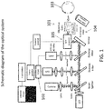
- FIG. 1 is a schematic diagram of an optical device. Fluorescence excitation is achieved by a pulsed laser beam that is focused by a high numerical aperture objective lens 101 into the eye. Fluorescence is detected using a time correlation single photon counting (TCSPC) technique through a confocal configuration with a fast avalanche photodiode detector (APD) 102. TCSPC is performed by using a short pulse of light to excite the sample (eye) 103 repetitively, and recording the subsequent fluorescence emission as a function of time. This usually occurs on the nanosecond timescale.
- TCSPC time correlation single photon counting
- identification of the anatomical structures of the lens is performed by scanning the objective lens 101 on axis using a translation stage 104.
- the signal is measured at every point along the scan in order to reveal the anatomical structures of the anterior segments such as the cornea, lens capsule and supranucleus region of the lens.
- the scan provides information about the pharmaco-kinetics of exogenous amyloid-binding compounds applied to the eye. Such information provides not only spatial and temporal information of the amyloid-binding compound, but also the concentration of the amyloid-binding compound that penetrates through the cornea and into the aqueous humor.
- one or more modules may be implemented using dedicated, specialized hardware modules and/or using a general purpose computer specially-programmed to perform the modules' functionality, including, for example, the Frame Grabber module, TCSPC module, ⁇ Calculation module and scanner control module.
- a general purpose computer and/or one or more specialized hardware modules may receive data from each other via data cables and data ports appropriate for the modules' functionality.
- the decay curve of the autofluorescence is registered for each scanned location of the lens and thus a two-dimensional representation of the fluorophores' distributions can be evaluated and analyzed based on their fluorescence decay time as well as on their intensity.
- the image of the calculated decay times can be encoded by false colors and can be superimposed on the intensity image for better clinical interpretation. Since the fluorescence decay time is a characteristic for each fluorescence molecule, one can determine and separate the fluorophores (amyloid-binding compound from natural fluorescence of the lens) being excited in the sample volume. By combining fluorescence intensity and lifetime measurements, an extra dimension of information is obtained to discriminate among several fluorescent labels.
- a device disclosed herein may comprise a light source.
- a "light source” may be any light source that can be configured to emit light to illuminate the eye with at least one of a wavelength and a polarization of light appropriate to produce fluorescence in at least an amyloid-binding compound when the amyloid-binding compound is bound to the amyloid protein, in a fashion such that the time decay rate of fluorescence may subsequently be determined based on the fluorescence that is received as a result of the illumination.
- the light source may be configured to emit light of an appropriate wavelength for a peak region of a fluorescent excitation spectrum for the amyloid-binding compound bound to the amyloid protein in the eye
- the optical unit may be configured to detect light of an appropriate wavelength for a peak region of a fluorescent emission spectrum for the amyloid-binding compound bound to the amyloid protein in the eye.
- the excitation spectrum has a peak of about 470 nm
- the light source may be configured to emit light within plus or minus about 20 nm of the peak of about 470 nm, such as within plus or minus 5 nm, plus or minus 10 nm, plus or minus 15 nm or plus or minus 20 nm of 470 nm.
- the emission spectrum for Compound #11 has a peak of about 580 nm
- the optical unit may be configured to detect light within plus or minus about 20 nm of the peak of about 580 nm, such as within plus or minus 5 nm, plus or minus 10 nm, plus or minus 15 nm or plus or minus 20 nm of 580 nm.
- an emission spectrum having a peak greater than about 500 nm is advantageous for distinguishing from the natural autofluorescence of the eye.
- Compound #11 proves useful for such a purpose, having an emission spectrum with a peak of about 580 nm, shifted significantly from the excitation spectrum with a peak of about 470 nm.
- FIG. 12 is an emission spectrum of the fluorescent amyloid-binding compound Compound # 11 when excited at 470nm, in accordance with an embodiment of the invention.
- Other excitation and emission spectra that may be used will be apparent to those of skill in the art based on the foregoing.
- the device disclosed herein may use an "optical unit,” which as used herein means any unit that can be configured to receive light including fluorescence produced as a result of the illumination of the eye and to determine a time decay rate of fluorescence for at least the fluorescence produced by the amyloid-binding compound bound to the amyloid protein, the determining permitting distinguishing of the presence of the amyloid-binding compound bound to the amyloid protein in the eye based at least on the time decay rate.
- an optical unit which as used herein means any unit that can be configured to receive light including fluorescence produced as a result of the illumination of the eye and to determine a time decay rate of fluorescence for at least the fluorescence produced by the amyloid-binding compound bound to the amyloid protein, the determining permitting distinguishing of the presence of the amyloid-binding compound bound to the amyloid protein in the eye based at least on the time decay rate.
- the optical unit may include one or more of the objective lens 101, translation stage 104, scanner 105, photodetector 102, a camera, an LED, the various lenses, apertures, beam splitters, dichroic filters, the time decay calculation module, the frame grabber module, the TCSPC module, and the scanner control module. Portions of the functionality of the optical unit may be implemented by a specially-programmed general purpose computer, or by dedicated hardware, for example for performing time decay calculations.
- optical scanning unit may refer to any device or collection of devices that perform the equivalent function of scanning a light beam over desired regions of interest in the eye, including for the purpose of determining reference points within the eye and for the purpose of analyzing fluorophores within the eye.
- Such an optical scanning unit may perform the functions of inducing translation motion of a lens, or motion of lens along a multi-dimensional path of motion; and may perform the functions of scanning the light over regions of interest, for example performing a point, planar, volumetric or other type of scan of the light beam over regions of interest, for example by inducing motion in a mirror or other optical device in the optical path of a light beam.
- a confocal arrangement means that a dilation agent need not be used, as may be required in systems in which light needs to enter the eye off-axis, for example, at a 45-degree angle. This is of convenience to patients.
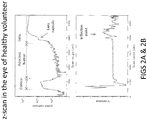
- FIG. 2A is a graph of natural fluorescence intensity versus displacement, measured during performance of an algorithm for detecting a lens interface in a scan along the illumination path (z-scan) of the eye
- FIG. 2B is a graph of the first derivative of the graph of FIG. 2A .
- the algorithm determines the distance from the z-scan start point that corresponds to the maximum inflection point in the fluorescence intensity.
- the algorithm proceeds as follows, and may run in real time:
- a location of the lens capsule may be determined using the above technique. Further, the locations of, and distances between, anatomical structures such as the cornea, aqueous humor and lens may also be determined. An offset may be applied to specify a distance of a measurement from a specific datum along any axis.
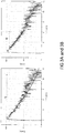
- FIGS. 3A and 3B are graphs illustrating determination of fluorescence decay time.
- Fluorescence decay time may be calculated by a single or double fit exponential ( FIG. 3A ) to a curve of intensity (here, in photons/sec), versus time (here, in nanoseconds). It can be also obtained by a linear fit to the slope ( FIG. 3B ).
- a "time decay rate of fluorescence” signifies a characteristic time constant of a decay curve of fluorescence intensity; for example, an exponential time constant or a slope fitted to the fluorescence decay curve.
- FIGS. 2A, 2B and 3A, 3B may, for example, be implemented using dedicated, specialized hardware modules and/or using a general purpose computer specially-programmed to perform the above algorithms.
- Such modules may, for example, use or receive data from the TCSPC module, Frame Grabber module, ⁇ -calculation module of the embodiment of FIG. 1 .
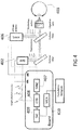
- FIG. 4 is a schematic diagram illustrating the use of time-correlation single photon counting.
- a pulsed light source 406 excites the sample 403 repetitively.
- the sample emission is observed by a detector unit avalanche photodiode (APD) 402, while the excitation flashes are detected by a synchronization module (SYNC) 407.
- a constant fraction discriminator (CFD) 408 responds to only the first photon detected - independent of its amplitude - from the detector 402. This first photon from sample emission is the stop signal for the Time-to- Amplitude Converter (TAC) 409.
- TAC Time-to- Amplitude Converter
- the excitation pulses trigger the start signals.
- the Multi- Channel Analyzer (MCA) 410 records repetitive start-stop signals of the single-photon events from the TAC 409, to generate a histogram of photon counts as a function of time channel units. The lifetime is calculated from this histogram.
- the MCA may be implemented using a dedicated, specialized hardware module and/or using a general purpose computer specially-programmed to perform such tasks
- a system comprising a fluorescent amyloid-binding compound and a device is intended to aid in the diagnosis of probable Alzheimer's disease in patients who have symptoms and signs consistent with Alzheimer's-type dementia following an adequate clinical examination.
- the device employs a confocal scanning mechanism combined with a fluorescence lifetime spectroscopy technique.
- the device enables identification of the anatomical structures of the anterior segments of the eye and discrimination of fluorescent fluorophores based on their optical signatures.
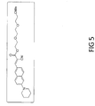
- FIG. 5 shows the structure of Compound #11, which is used as a fluorescent amyloid-binding compound in accordance with the invention.
- Compound #11 is a fluorescent compound designed according to the molecular rotor motif, and has been shown to bind to the aggregated beta-amyloid (A ⁇ ) peptide. This, combined with native fluorescence, suggests that Compound #11 is a good candidate for an in vivo marker for A ⁇ aggregates which have been found in the lens tissue of Alzheimer's patients.
- the chemical name for Compound #11 is [(E)-2-(2-(2-methoxyethoxy)ethoxy)ethyl-2-cyano-3-(6-(piperidin-1-yl)naphthalen-2-yl)acrylate].
- Compound #11 has been formulated into an ophthalmic ointment (Compound #11 Ophthalmic Ointment) containing approximately 5 mg/g of Compound #11, 80% petrolatum and 20% mineral oil.
- a fluorophore amyloid-binding compound may be applied to an eye of an individual to be tested in any of a variety of different possible forms.
- the fluorophore amyloid-binding compound may be applied as an ointment, a solution, using a contact lens, by injection, in liquid form, in solid form, by iontophoresis, or by other techniques.
- a device disclosed herein is designed to detect fluorescence in the time domain with high sensitivity and speed in a confocal detection scheme.
- the device has two main functionalities: 1) delivery and scanning of the optical beam to locations in the anterior segments of the eye, such as the supranucleus of the lens, using a translation stage and a galvanometer scanner; and 2) identification and discrimination of fluorescent fluorophores based on fluorescence lifetime measurements.
- a device identifies ocular anatomical structures using an axial scan or z-scan, which is based on the laser excitation of natural fluorescence of ocular tissues along the optic axis of the eye to obtain information on intraocular distances.
- the z-scan reveals a plot of natural fluorescence intensity as a function of depth that provides information about the location where lifetime measurements are to be performed.
- the targeted location may, for example, be the supranucleus of the lens in the human eye.
- the scanning may be completed in seconds, for example in 2 seconds or less, such as in about 0.2 seconds, 0.3 seconds, 0.4 seconds, 0.5 seconds, 0.6 seconds, 0.7 seconds, 0.8 seconds, 0.9 seconds, 1.0 seconds, 1.2.
- the device may be used in conjunction with eye-motion tracking to reduce motion artifacts. Piezo drives, linear motors and other controlled motion devices may be used for such a purpose.
- the axial scan may also allow measurement of the gradient concentration of amyloid-binding compound at ocular interfaces such as tear film/corneal epithelial interface, as well as amyloid-binding compound bioavailability in the aqueous humor.
- a device identifies fluorescent molecules by performing an xy-scan, in which the sample is raster-scanned with a galvanometer-driven device.
- the fluorescence lifetime is registered for each location scanned of the human lens and thus a two-dimensional representation of the fluorophore distribution can be evaluated and analyzed based on fluorescence decay rate as well as intensity.
- a two-dimensional representation of fluorophore distribution based on decay lifetime which may also, but need not necessarily, include a two-dimensional representation based on fluorescence intensity, is referred to herein as a "fluorescence lifetime image.”
- fluorescence lifetime measurements are based on repetitively exciting the eye with short laser pulses and recording the subsequent fluorescence emission as a function of time. Since the fluorescence decay time is a characteristic of each fluorescence molecule, one can determine and separate the amyloid-binding compound from natural fluorescence of the lens that is being excited in the sample volume.
- fluorescence lifetime measurements may be obtained by a time correlation single photon counting technique (TCSPC).
- TCSPC time correlation single photon counting technique
- the scanning speed and data acquisition may be synchronized and executed, for example, in 0.5 seconds to reduce any eye motion artifacts, or another amount of time appropriate to reduce eye motion artifacts.
- the TCSPC principle is based on the detection of single photons emitted by a pulsed laser and recording of the detection times of the arriving individual photons. When a photon is detected, the time of the corresponding detector pulse is measured. The events are collected in memory for many detected photons. Fluorescence decay lifetimes can be calculated by constructing a histogram from the individual time measurements.
- a device operating in TCSPC mode can achieve, for example, count rates of about 10 7 photons per second. Therefore, 10 4 photons can be collected in less than 1 ms. Such count rates are important where high speed is necessary to acquire fast scanning information in the lens of the human eye. Other count rates may be used.
- a device may be designed to obtain specific information from a particular location in the lens of the human eye. Examples of such locations include the supranucleus, lens capsule, nucleus, cornea and aqueous humor.
- Fluorescence excitation is achieved by a pulsed laser beam that is focused by a high numerical aperture objective lens 101 into the eye 103.
- the laser may, for example, be pulsed at a repetition rate of about 40MHz and produce pulses of about 200 picoseconds wide, although other repetition rate and pulse widths may be used. For example, repetition rates from as low as about 1 MHz up to about 240 MHz may be used, and pulse widths of from about 40 picoseconds to about 400 picoseconds may be used.
- the optical beam then is reflected off a pair of galvanometer scanners and is focused by a high numerical objective lens 101 which is mounted on a translation stage 104.
- the fluorescence measurements in the supranucleus of the eye are obtained by first aligning the subject eye to the device and performing 1) a z-scan to determine the location of the region of interest (ROI) and 2) an xy-scan to obtain specific information over an area within the supranucleus.
- ROI region of interest
- Subject alignment consists of identifying the focal plane of the objective lens as a reference starting point of the measurement.
- a light emitting diode (LED) which is used also as a fixation target, is focused by the objective lens 101 onto the cornea of the eye 103 in the shape of a ring.
- a camera is used to visualize the reflection of the ring off the surface of the cornea. Once this is achieved, the scanning of the eye can be performed to obtain the necessary information.
- Identification of the anatomical structures of the lens is performed by scanning the objective lens 101 along the optical axis (on axis) using a translation stage 104.
- the z-scan involves the excitation of the natural fluorescence with the laser source and identification of the anatomical structures of the anterior segments such as the cornea, lens capsule and supranucleus region of the lens and their relative distances.
- the scan can provide information about the pharmacokinetics of exogenous amyloid-binding compound applied to the eye.
- a planar scan in the plane perpendicular to the axial scan is performed using the galvanometer mirrors.
- the galvanometer mirrors are synchronized with the data acquisition board for TCSPC measurements.
- An xy-scan may entail, for example, scanning a region 50 by 50 ⁇ m in the supranucleus of a human eye in 0.5 seconds and extracting lifetime decay values. It will be appreciated that regions of other sizes and locations, and times of scans, may be used.
- Detection is achieved with TCSPC through a confocal configuration with a fast avalanche photodiode detector (APD) 102. Fluorescence from the excited molecules is collected with the same objective lens 101 as the excitation laser, filtered after the dichroic mirror with an additional band-pass filter to reject remaining scattered laser light and passed through a small aperture to enable confocal detection.
- the APD 102 may, for example, provide timing resolution better than 50 picoseconds Full Width Half Maximum with photon detection efficiency of 49% at 550 nm, although other timing resolutions and photon detection efficiencies may be used.
- the pulsed light source 406 excites the sample 403 repetitively at (for example) a 40MHz repetition rate while the excitation pulses are detected by a synchronization (SYNC) module 407 which is set (for example) also at 40MHz.
- the excitation pulses trigger the start signals.
- a constant fraction discriminator (CFD) 408 responds to only the first photon detected from the detector, independent of its amplitude. This first photon from sample emission is the stop signal for the Time-to-Amplitude Converter (TAC) 409.
- TAC Time-to-Amplitude Converter
- the pulse is "cleaned” by the CFD 408 and enters the TAC 409 as a "stop” pulse.
- the stop pulse i.e., the first arriving photon
- the voltage ramp is stopped and the voltage value (equivalent to the time difference between the start and stop pulses) is transmitted to the Multi-Channel Analyzer (MCA) 410.
- MCA Multi-Channel Analyzer
- the MCA 410 records repetitive start-stop signals of the single-photon events from the TAC 409 and increments the counts in the channel in correspondence with the detected voltage (time). This process is repeated with each pulse and eventually, after many cycles, a histogram of photon counts as a function of time channel units is generated.
- the histogram represents the fluorescence intensity as a function of time, from which the fluorescence decay lifetime is obtained.
- the data acquisition may be performed using the PicoHarp 300 TCSPC (PicoQuant, GmbH, Berlin, Germany) PC-board working in the special Time-Tagged Time-Resolved Mode, which stores all relevant information for every detected photon for further data analysis.
- every photon arrival time is recorded at the detector in synchronization with the laser excitation pulse and the position of the sample and the number of the detection channel.
- the sync rate of the acquisition board may, for example, be set at 40 MHz with a time resolution of 4 picoseconds and channel count depth of 16 bit (other sync rates, time resolutions and channel count depths may be used).
- the software acquisition which may be performed using SymPhoTime, (PicoQuant, GmbH, Berlin, Germany), may be controlled via a TCP/IP network and synchronized with both the galvanometer scanner and the acquisition board through TTL signals to define the line and the frame of the image.
- SymPhoTime in LSM command mode may, for example, record and display the fluorescence lifetime and intensity images.
- the fluorescence lifetime may be registered for each location scanned within the human lens, and thus a two-dimensional representation of the fluorophore distribution can be evaluated and analyzed based on fluorescence decay rate and intensity.
- a constructed color coded image based on fluorescence lifetime decay can be superimposed on the intensity image to facilitate clinical interpretation.
- the calculation of a fluorescence lifetime image may be done by sorting all photons which correspond to one pixel into a histogram, which is then fitted to an exponential decay function to extract the lifetime information. This procedure is then repeated for every pixel in the image.
- the software algorithm may fit the data to multi-exponential decay functions using tail-fitting as well as numerical re-convolution.
- frequency count of photons of specific decay rates that is indicative of specific fluorophores over an area scan can be extracted directly from the image.
- the foregoing algorithms may be implemented by computer, and may involve displaying data on a two-dimensional display such as a computer monitor.
- An average intensity associated with a specific lifetime decay may be used as a measure of aggregation of amyloid proteins. That is, a parameter can be created by averaging a fluorescent intensity, associated with a specific lifetime decay, over a specific area. This parameter can be used as a measure of aggregation, for example to monitor progression of a disease in an individual based on changes in the parameter. Such a parameter may be determined by computer or other specialized hardware.
- a fluorescent histogram of the fluorescent amyloid-binding compound Compound #11 is shown in FIG. 6 , obtained by a device. Single exponential fitting results in a lifetime decay rate of 2 nsec.
- FIG. 7 shows a fluorescence lifetime image of Compound #11 and its corresponding intensity image, obtained in accordance with an embodiment of the invention.
- the images are 100 X 100 pixels obtained in 0.5 seconds and represent a scanning area of 50 X 50 microns.
- An embodiment according to the invention uses a fluorescence time domain technique to detect and resolve fluorophores based on their lifetime signature. By combining fluorescence intensity and lifetime measurements, an extra dimension of information is obtained to discriminate among fluorescent labels.
- In vitro studies discussed in Experiment #1 demonstrate the capability of an embodiment according to the invention in differentiating fluorescent fluorophores based on their lifetime decay signature.
- the pharmacokinetics studies on rabbit eyes discussed in Experiment #2 show detectable fluorescence signal of the fluorescent amyloid-binding compound Compound #11 in the supranucleus of the lens. More important, the signal detected in the lens of the rabbit eye was easily identified and assigned to the amyloid-binding compound itself.
- any method presented herein (as well as individual steps thereof and combinations of several subsequent steps of these methods), in particular the technical steps involving the collection and optionally processing of relevant data, the comparison of the data thus obtained with the normal control values and/or the finding of any significant deviation during that comparison, may be performed ahead of, independent thereof and in preparation of a subsequent, separate diagnosis step, i.e., prior to attributing a potential deviation between the values obtained and the normal control value(s) to a particular amyloidogenic disorder such as Alzheimer's disease (the actual diagnosis).
- These methods (including individual steps as well as combinations of several subsequent steps of these methods) performed ahead of, independent thereof and in preparation of a subsequent, separate diagnosis are specifically contemplated as individual embodiments not forming part of the current invention.
- excitation sources may be the Picosecond Pulsed Laser, LDH series, sold by PicoQuant of Berlin, Germany; the Picosecond Diode Laser, BDL series, sold by Becker & Hickl of Berlin, Germany; or the Picosecond Light Pulser, PLP series, sold by Hamamatsu Photonics of Hamamatsu, Japan.
- Data acquisition may be performed using the TCSPC module, PicoHarp 300, sold by PicoQuant, Berlin, Germany; the TCSPC module, SPC series, sold by Becker & Hickl, Berlin, Germany; or the Synchronous Delay Generator, C10647 sold by Hamamatsu Photonics, Hamamatsu, Japan.
- Photon Counting Detectors may be the Detector Unit, PMA series, sold by PicoQuant, Berlin, Germany; the Detector Unit, ID-100 Series, sold by Becker & Hickl, Berlin, Germany; or the Streakscope (C10627 series, sold by Hamamatsu Photonics, Hamamatsu, Japan). It will be appreciated that other excitation sources, data acquisition modules and photon counting detectors may be used.
- Portions of the above-described embodiments not forming part of the invention disclosed herein can be implemented using one or more computer systems.
- the embodiments may be implemented using hardware, software or a combination thereof.
- the software code can be executed on any suitable processor or collection of processors, whether provided in a single computer or distributed among multiple computers.
- a computer may be embodied in any of a number of forms, such as a rack-mounted computer, a desktop computer, a laptop computer, a tablet computer, a single circuit board computer or a system on a chip. Additionally, a computer may be embedded in a device not generally regarded as a computer but with suitable processing capabilities, including a Personal Digital Assistant (PDA), a smart phone or any other suitable portable or fixed electronic device.
- PDA Personal Digital Assistant
- a computer may have one or more input and output devices. These devices can be used, among other things, to present a user interface. Examples of output devices that can be used to provide a user interface include printers or display screens for visual presentation of output and speakers or other sound generating devices for audible presentation of output. Examples of input devices that can be used for a user interface include keyboards, and pointing devices, such as mice, touch pads, touch screens and digitizing tablets. As another example, a computer may receive input information through speech recognition or in other audible format.
- Such computers may be interconnected by one or more networks in any suitable form, including as a local area network or a wide area network, such as an enterprise network or the Internet.
- networks may be based on any suitable technology and may operate according to any suitable protocol and may include wireless networks, wired networks or fiber optic networks.
- the various methods or processes outlined herein may be coded as software that is executable on one or more processors that employ any one of a variety of operating systems or platforms. Additionally, such software may be written using any of a number of suitable programming languages and/or programming or scripting tools, and also may be compiled as executable machine language code or intermediate code that is executed on a framework or virtual machine.
- At least a portion of the present disclosure may be embodied as a computer readable medium (or multiple computer readable media) (e.g., a computer memory, one or more floppy discs, compact discs, optical discs, magnetic tapes, flash memories, circuit configurations in Field Programmable Gate Arrays or other semiconductor devices, or other tangible computer storage medium) encoded with one or more programs that, when executed on one or more computers or other processors, perform methods that implement at least a portion of the various embodiments discussed above.
- the computer readable medium or media can be transportable, such that the program or programs stored thereon can be loaded onto one or more different computers or other processors to implement various aspects as discussed above.
- one implementation of at least a portion of the above-described embodiments comprises at least one computer-readable medium encoded with a computer program (e.g., a plurality of instructions), which, when executed on a processor, performs some or all of the above-discussed functions of these embodiments.
- a computer program e.g., a plurality of instructions
- the term "computer-readable medium” encompasses only a computer-readable medium that can be considered to be a machine or a manufacture (i.e., article of manufacture).
- a computer-readable medium may be, for example, a tangible medium on which computer-readable information may be encoded or stored, a storage medium on which computer-readable information may be encoded or stored, and/or a non-transitory medium on which computer-readable information may be encoded or stored.
- Other non-exhaustive examples of computer-readable media include a computer memory (e.g., a ROM, a RAM, a flash memory, or other type of computer memory), a magnetic disc or tape, an optical disc, and/or other types of computer-readable media that can be considered to be a machine or a manufacture.
- program or “software” are used herein in a generic sense to refer to any type of computer code or set of computer-executable instructions that can be employed to program a computer or other processor to implement various aspects of the present invention as discussed above. Additionally, it should be appreciated that according to one aspect of this embodiment, one or more computer programs that when executed perform methods of the present invention need not reside on a single computer or processor, but may be distributed in a modular fashion amongst a number of different computers or processors to implement various aspects of the present invention.
- Computer-executable instructions may be in many forms, such as program modules, executed by one or more computers or other devices.
- program modules include routines, programs, objects, components, data structures, etc. that perform particular tasks or implement particular abstract data types.
- functionality of the program modules may be combined or distributed as desired in various embodiments.
- FIG 8A is a fluorescence lifetime image showing Compound #11 and Compound #11 bound to aggregated A ⁇ peptide, with their corresponding fluorescence lifetime histograms shown in FIG. 8B . By fitting the lifetime histograms, the decay rates are determined.
- the results demonstrate the superior performance of an embodiment in accordance with the invention that is capable of differentiating between fluorophores of lifetime difference of as little as 0.85 nsec with low level of photon detection.
- the purpose of this in vitro study was to identify the optical signature of the Compound #11 amyloid-binding compound, and to characterize its fluorescence properties when bound to aggregated A ⁇ peptide.
- the objectives of the study were: 1) characterization of Compound #11 lifetime decay rates; and 2) ability to detect and differentiate between Compound #11 bound and un-bound to beta amyloid (A ⁇ ) peptides.
- the Neuroptix SAPPHIRE II device (Neuroptix Corporation, Acton, MA, U.S.A.) is a purpose built device for clinical studies in humans, which was adapted for in vitro measurements for this experiment. It employs a confocal scanning mechanism combined with fluorescence lifetime spectroscopy that allows differentiation of fluorophores.
- the device allows 1) scanning of the optical beam to specific locations in the anterior segments of the eye, such as the supranucleus and 2) identification of fluorescent fluorophores based on fluorescence lifetime measurements.
- Aggregated A ⁇ peptide was prepared by dissolving A ⁇ (1-42) in PBS pH 7.4 to a final concentration of 100 ⁇ M. This solution was magnetically stirred at 1200 rpm for 3 days at room temperature. The 100 ⁇ M A ⁇ (1-42) stock solution in PBS was aliquoted and frozen at -80 °C for up to 4 weeks without noticeable change in its property. 150 ⁇ L of pre-aggregated A ⁇ (1-42) was added to 2.85 mL of Compound #11 to attain a final concentration of 5 ⁇ M A ⁇ (1-42) and 4 ⁇ M of Compound #11. The solution was transferred to 5 mL vial and the fluorescence measurements were performed at 25 °C.
- FIG. 8A shows an image (200 ⁇ 200 pixels) with a scan range of 100 ⁇ m ⁇ 100 ⁇ m obtained in 1 second acquisition time.
- the image is shaded to represent lifetime decays.
- the shading that makes up most of the image background represents a lifetime decay of 1.4 nsec, which corresponds to that of the fluorescence amyloid-binding compound.
- the spot detected in the image is that of the aggregated A ⁇ peptide representing a lifetime decay of 2.25 nsec.
- the plot in FIG. 8B shows the fluorescence decay rates calculated for both the Compound #11 and that of the Compound #11 bound to aggregated A ⁇ peptide.
- FIG. 9A is a plot of the frequency count of photons of specific decay rates measured on two rabbits dosed with the amyloid-binding compound along with a controlled rabbit.
- the frequency count of photons of specific decay rates that pertained to the fluorescent amyloid-binding compound (Compound#11) was calculated from the fluorescence histogram ( FIG. 9B ).
- the results demonstrate the capability of the amyloid-binding compound to penetrate the cornea and be detected by the device in the lens of rabbit eyes.
- the study was staggered over four days and performed in a single location and on asingle instrument. Tests were performed in a dimly lit room dedicated to the study.
- Fluorescence lifetime and intensity measurements were performed in the eye at the beginning and at the end of each day.
- the measurements entailed scanning the rabbit eye axially (z-scan) to obtain inter-ocular information and a planar scan (xy-scan) to perform lifetime decay measurements in a certain region of the eye, which is the lens nucleus in this case.
- Time Correlation Single Photon Counting was initiated while performing the xy-scan.
- the fluorescence lifetime images were then obtained where the decay lifetime histogram was obtained for each pixel location.
- the calculated decay times were color coded in the fluorescence lifetime image.
- Each measurement was performed three times.
- the frequency count of photons of specific decay rates were calculated from the decay rates frequency that of the Compound #11 signature obtained in the xy-scan and averaged over the three measurements.
- Calibration measurements were taken once a day on a fluorescence dye and showed repeatable performance with no apparent drift throughout the study.
- the device was specifically designed for human use but the platform was slightly modified for holding the rabbits.
- Dosing was performed by Toxikon staff via topical ocular application into the right eye of each animal.
- Group 1 Animals were anesthetized with subcutaneous injection of Dexdomitor (0.5mg/kg), Ketamine (5mg/kg). A ribbon of ointment approximately 1 ⁇ 2 inch long was then applied to the lower right eyelid of each animal in the test group three times a day for four days.
- Control For the control group, one animal was handled in the same way as the animals in the test groups except no ointment or solution was administered to the eye.
- FIGS. 10A and 10B are plots showing the frequency count of photons of specific decay rates that pertain to Compound #11 measured in the morning for baseline and at the end of the day after being dosed during the four day study period in the lens nucleus of the five rabbits.
- FIG. 10A is a plot for the morning measurements
- FIG. 10B is a plot for the evening measurements, both being on rabbits dosed with Compound #11 Ophthalmic Ointment.
- FIGS. 10A and 10B show that after three dosages each day with three hours separation, a cumulative fluorescence signal is measured along the 4 day study period.
- FIGS. 11A and 11B are two fluorescence lifetime images taken at baseline and after the end of the fourth day of the study with animal 1003.
- the baseline measurement exhibited a black image indicative of no presence of Compound #11 in the lens of the eye.
- an xy-scan revealed a lifetime image with a decay rate of 2 nsec (displayed in gray) which is a signature of the fluorescence lifetime.
- the difference in signal collected between the two rabbits can be attributed to the dosing variation by the technician and blinking by the animal.
- Compound #11 Ophthalmic Ointment at a concentration of 5 mg/g. Repetitive topical administration of Compound #11 tended to accumulate in the nucleus after several hours of application and tended to stay there for at least 12 hours.
Claims (4)
- Verfahren zum Nachweis eines Amyloidproteins in einem Auge eines Säugetiers, wobei das Verfahren umfasst:Beleuchten des Auges mit einer Lichtquelle (406), die mindestens eine Wellenlängeneigenschaft, eine Polarisationseigenschaft oder eine Kombination davon aufweist, die jeweils geeignet sind, Fluoreszenz in mindestens einer Amyloid-bindenden Verbindung zu erzeugen, wenn die Amyloid-bindende Verbindung an das Amyloid-Protein gebunden ist, wobei die Amyloid-bindende Verbindung in das Auge eingeführt wurde und spezifisch an das Amyloid-Protein bindet, das auf die amyloidogene Störung hinweist;
Empfangen von Licht einschließlich Fluoreszenz, die als Ergebnis des Beleuchtens des Auges erzeugt wird; undBestimmen einer zeitlichen Abklingrate der Fluoreszenz für mindestens die Fluoreszenz, die von der an das Amyloidprotein gebundenen Amyloid-bindenden Verbindung erzeugt wird, wobei das Bestimmen die Unterscheidung des Vorhandenseins der an das Amyloidprotein gebundenen Amyloid-bindenden Verbindung in dem Auge auf der Grundlage von mindestens der zeitlichen Abklingrate erlaubt;wobei das Verfahren ferner umfasstErfassen der vom Auge erzeugten Fluoreszenz unter Verwendung einer Photodetektorvorrichtung;Durchführen einer zeitkorrelierten Einzelphotonenzählung der von dem Auge erzeugten Fluoreszenz, was das Pulsen der Lichtquelle und das Bestimmen der zeitlichen Abklingrate der Fluoreszenz auf der Grundlage einer Verteilung der Photonenzahlen als eine Funktion der Zeitkanaleinheiten umfasst;Beleuchten des Auges mit Licht einer geeigneten Wellenlänge für einen Spitzenbereich eines Fluoreszenzanregungsspektrums für die an das Amyloidprotein im Auge gebundene Amyloid-bindende Verbindung und Erfassen des vom Auge empfangenen Lichts einer Wellenlänge, die geeignet ist für einen Spitzenbereich eines Fluoreszenzemissionsspektrums für die an das Amyloidprotein im Auge gebundene Amyloid-bindende Verbindung; undwobei die Amyloid-bindende Verbindung [(E)-2-(2-(2-Methoxyethoxy)ethoxy)ethyl-2-cyano-3-(6-(piperidin-1-yl)naphthalen-2-yl)acrylat] ist, das Anregungsspektrum einen Peak von 470 nm aufweist, das Beleuchten des Auges bei einer Wellenlänge innerhalb von plus oder minus 20 nm des Peaks des Anregungsspektrums liegt, und das Emissionsspektrum einen Peak von 580 nm aufweist, das Erfassen des vom Auge empfangenen Lichts bei einer Wellenlänge innerhalb von plus oder minus 20 nm des Peaks des Emissionsspektrums liegt. - Verfahren nach Anspruch 1, wobei die Photodetektorvorrichtung mindestens eine Photodiode, einen Photomultiplier, eine ladungsgekoppelte Vorrichtung oder eine verstärkte ladungsgekoppelte Vorrichtung umfasst.
- Verfahren nach Anspruch 2, wobei die Photodetektorvorrichtung einen schnellen Avalanche-Photodiodendetektor umfasst.
- Verfahren nach einem der Ansprüche 1 bis 3, wobei das Verfahren eine Echtzeitsuche innerhalb des Auges nach dem Amyloidprotein ermöglicht, das auf die amyloidogene Störung hinweist.
Priority Applications (1)
| Application Number | Priority Date | Filing Date | Title |
|---|---|---|---|
| EP11745903.2A EP2605694B1 (de) | 2010-08-16 | 2011-08-12 | Verfahren für den nachweis von amyloidproteinen |
Applications Claiming Priority (5)
| Application Number | Priority Date | Filing Date | Title |
|---|---|---|---|
| US37413110P | 2010-08-16 | 2010-08-16 | |
| US201061425490P | 2010-12-21 | 2010-12-21 | |
| EP11001148 | 2011-02-11 | ||
| EP11745903.2A EP2605694B1 (de) | 2010-08-16 | 2011-08-12 | Verfahren für den nachweis von amyloidproteinen |
| PCT/US2011/047628 WO2012024188A1 (en) | 2010-08-16 | 2011-08-12 | System and method for detecting amyloid proteins |
Publications (2)
| Publication Number | Publication Date |
|---|---|
| EP2605694A1 EP2605694A1 (de) | 2013-06-26 |
| EP2605694B1 true EP2605694B1 (de) | 2021-10-27 |
Family
ID=44168199
Family Applications (2)
| Application Number | Title | Priority Date | Filing Date |
|---|---|---|---|
| EP11006656.0A Active EP2420179B1 (de) | 2010-08-16 | 2011-08-12 | System und Verfahren zum Nachweis von Amyloidproteinen |
| EP11745903.2A Active EP2605694B1 (de) | 2010-08-16 | 2011-08-12 | Verfahren für den nachweis von amyloidproteinen |
Family Applications Before (1)
| Application Number | Title | Priority Date | Filing Date |
|---|---|---|---|
| EP11006656.0A Active EP2420179B1 (de) | 2010-08-16 | 2011-08-12 | System und Verfahren zum Nachweis von Amyloidproteinen |
Country Status (15)
| Country | Link |
|---|---|
| US (2) | US9220403B2 (de) |
| EP (2) | EP2420179B1 (de) |
| JP (2) | JP5863797B2 (de) |
| KR (1) | KR101905436B1 (de) |
| CN (1) | CN103153168B (de) |
| AR (1) | AR082707A1 (de) |
| AU (1) | AU2011292233B2 (de) |
| BR (1) | BR112013003754B1 (de) |
| CA (1) | CA2807683C (de) |
| MX (1) | MX357628B (de) |
| NZ (1) | NZ607257A (de) |
| RU (1) | RU2577810C2 (de) |
| SG (1) | SG188227A1 (de) |
| TW (1) | TWI476392B (de) |
| WO (1) | WO2012024188A1 (de) |
Families Citing this family (33)
| Publication number | Priority date | Publication date | Assignee | Title |
|---|---|---|---|---|
| BRPI0909519B8 (pt) * | 2008-03-27 | 2021-06-22 | Cognoptix Inc | sistema para realizar a difusão de luz quase-elástica e a varredura de ligante fluorescente em um olho do indivíduo |
| RU2577810C2 (ru) | 2010-08-16 | 2016-03-20 | Когноптикс, Инк. | Система и способ для обнаружения амилоидных белков |
| CA2834056A1 (en) * | 2011-04-27 | 2012-11-01 | Adlyfe, Inc. | Ocular detection of amyloid proteins |
| US9585558B2 (en) | 2011-12-09 | 2017-03-07 | Regents Of The University Of Minnesota | Hyperspectral imaging for early detection of Alzheimer'S Disease |
| US20130330711A1 (en) * | 2012-06-06 | 2013-12-12 | National Taiwan University | Sensor for detection of a target of interest |
| JP6133053B2 (ja) * | 2012-12-21 | 2017-05-24 | 浜松ホトニクス株式会社 | アミロイドの凝集体の定量方法及びその定量装置 |
| US20150042954A1 (en) * | 2013-08-08 | 2015-02-12 | University Of Rochester | System and Method for Fluorescence Lifetime Imaging Aided by Adaptive Optics |
| US20150065824A1 (en) * | 2013-08-28 | 2015-03-05 | Johnson & Johnson Vision Care, Inc. | Methods and apparatus to form ophthalmic devices incorporating fluorescence detectors |
| TW201609183A (zh) * | 2013-10-31 | 2016-03-16 | 康諾普堤克斯公司 | 眼用調配物之製備方法及其用途 |
| WO2015072964A1 (en) * | 2013-11-12 | 2015-05-21 | Cognoptix, Inc. | Method for measuring fluorescence in ocular tissue |
| CN103709069B (zh) * | 2014-01-07 | 2015-03-18 | 南方医科大学 | 一种6’-羟基萘基-2-氰基丙烯酸酯及其用途 |
| CN106573880B (zh) | 2014-03-19 | 2019-07-30 | 阿米达斯公司 | 淀粉样蛋白靶向剂及其使用方法 |
| JP2016014074A (ja) * | 2014-06-19 | 2016-01-28 | 国立研究開発法人物質・材料研究機構 | プログラム可能なナノロボットに添付されたセンサ、分子機械及びコントローラ |
| JP6550673B2 (ja) * | 2015-04-03 | 2019-07-31 | 国立大学法人 東京大学 | フォトルミネセンス寿命測定装置及び測定方法 |
| US11402328B2 (en) | 2015-09-29 | 2022-08-02 | Hamamatsu Photonics K.K. | Amyloid β oligomer detection method, amyloid β oligomer detection device, and amyloid β oligomer detection program |
| CN109073461B (zh) | 2016-03-10 | 2021-08-17 | 明尼苏达大学董事会 | 光谱-空间成像装置和方法以及成像系统 |
| EP3491391A4 (de) * | 2016-08-01 | 2020-04-29 | Cognoptix, Inc. | System und verfahren zur erkennung von tau-protein in augengewebe |
| US10405785B2 (en) * | 2016-08-04 | 2019-09-10 | City University Of Hong Kong | Determination of a concentration of an analyte in a subject |
| CA3031392A1 (en) * | 2016-09-16 | 2018-03-22 | Novartis Ag | Subtractive en face optical coherence tomography imaging |
| US9950189B1 (en) * | 2016-10-20 | 2018-04-24 | Neuro-Laser Foundation Inc. | Treatment methodologies using light therapy |
| US10905897B2 (en) * | 2016-10-20 | 2021-02-02 | Neuro-Laser Foundation, Inc. | Synergistic treatment methodologies using light therapy |
| KR101835815B1 (ko) * | 2016-12-16 | 2018-03-07 | (주) 인텍플러스 | 형광수명 측정장치 및 측정방법 |
| JP7035081B2 (ja) * | 2017-01-11 | 2022-03-14 | アヴェドロ・インコーポレーテッド | 角膜におけるクロスリンキング分布及び/又は角膜の構造的特徴を決定するためのシステム及び方法 |
| WO2018136910A1 (en) * | 2017-01-23 | 2018-07-26 | Rensselaer Polytechnic Institute | Systems and methods for binding amyloid fibrils using fluorescent protein |
| JP7007132B2 (ja) * | 2017-08-09 | 2022-01-24 | 浜松ホトニクス株式会社 | アミロイド凝集体の検出方法、アミロイド凝集体検出装置、及びアミロイド凝集体検出プログラム |
| CN111565624A (zh) | 2017-11-27 | 2020-08-21 | 雷蒂斯派克股份有限公司 | 用于阿尔茨海默氏病病理的高光谱图像指导的raman眼科成像仪 |
| CN108489941B (zh) * | 2018-01-31 | 2021-07-27 | 吉林大学 | 溴酚蓝在作为检测牛胰岛素淀粉样纤维探针和作为牛胰岛素淀粉样纤维抑制剂方面的应用 |
| MA52796A (fr) * | 2018-05-31 | 2021-04-14 | Amydis Inc | Compositions et procédés de détection d'une lésion cérébrale traumatique |
| US10746596B2 (en) * | 2018-06-18 | 2020-08-18 | Harry Owen | Probe optic light shields |
| JP7380013B2 (ja) * | 2019-09-26 | 2023-11-15 | 株式会社ニコン | 眼科装置、眼科装置の制御方法及びプログラム |
| JPWO2021192910A1 (de) * | 2020-03-23 | 2021-09-30 | ||
| GB2603006A (en) * | 2021-01-26 | 2022-07-27 | Edinburgh Biosciences Ltd | Apparatus and systems for monitoring and treating cataracts |
| US20240090763A1 (en) * | 2021-01-26 | 2024-03-21 | Edinburgh Biosciences Ltd | Apparatus and systems for monitoring and treating cataracts |
Family Cites Families (74)
| Publication number | Priority date | Publication date | Assignee | Title |
|---|---|---|---|---|
| JPS5836969B2 (ja) | 1978-01-23 | 1983-08-12 | 株式会社甲南カメラ研究所 | 眼球顕微鏡 |
| US4529556A (en) | 1983-08-19 | 1985-07-16 | The Dow Chemical Company | Bis((aryl)vinyl)benzenes |
| US4761071A (en) | 1984-11-06 | 1988-08-02 | Baron William S | Apparatus and method for determining corneal and scleral topography |
| US4702576A (en) | 1985-09-27 | 1987-10-27 | Cambridge Instruments Inc. | Ocular scattering analyzer |
| US5183044A (en) | 1987-06-30 | 1993-02-02 | Kabushiki Kaisha Topcon | Noncontact type tonometer |
| US4806004A (en) | 1987-07-10 | 1989-02-21 | California Institute Of Technology | Scanning microscopy |
| US4993827A (en) | 1987-09-01 | 1991-02-19 | Massachusetts Institute Of Technology | Method for detecting cataractogenesis |
| US4957113A (en) | 1987-09-01 | 1990-09-18 | Massachusetts Institute Of Technology | Method for detecting cataractogenesis using quasi-elastic light scattering |
| JPH0277228A (ja) | 1988-09-14 | 1990-03-16 | Kowa Co | 眼科測定装置 |
| JP2931325B2 (ja) | 1989-06-29 | 1999-08-09 | 興和株式会社 | 眼科測定装置 |
| US5048946A (en) | 1990-05-15 | 1991-09-17 | Phoenix Laser Systems, Inc. | Spectral division of reflected light in complex optical diagnostic and therapeutic systems |
| US5279296A (en) | 1991-01-04 | 1994-01-18 | Oculon Corporation | Method and apparatus for detecting cataractogenesis |
| US6198532B1 (en) | 1991-02-22 | 2001-03-06 | Applied Spectral Imaging Ltd. | Spectral bio-imaging of the eye |
| US5303709A (en) | 1991-12-16 | 1994-04-19 | Dreher Andreas W | Retinal eye disease diagnostic system |
| JPH05261068A (ja) | 1992-03-19 | 1993-10-12 | Topcon Corp | 眼科装置 |
| US5392776A (en) | 1992-09-21 | 1995-02-28 | Oculon Corporation | Method and apparatus for detecting cataractogenesis |
| US5548354A (en) | 1993-06-10 | 1996-08-20 | Konan Common Co., Ltd. | Method for observing and photographing a cornea and apparatus for the same |
| PT101290B (pt) | 1993-06-18 | 2000-10-31 | Fernandes Jose Guilherme Da Cu | Fluorometro para medicao da concentracao de fluoroforos de localizacao ocular |
| US5427094A (en) | 1993-11-08 | 1995-06-27 | Oculon Corporation | Method and apparatus for detecting cataractogenesis |
| US5427095A (en) | 1993-11-09 | 1995-06-27 | Massachusetts Institute of Technology Oculon Corporation | Method and apparatus for detecting cataractogenesis |
| US6417178B1 (en) | 1994-07-19 | 2002-07-09 | University Of Pittsburgh | Amyloid binding nitrogen-linked compounds for the antemortem diagnosis of alzheimer's disease, in vivo imaging and prevention of amyloid deposits |
| US6168776B1 (en) | 1994-07-19 | 2001-01-02 | University Of Pittsburgh | Alkyl, alkenyl and alkynyl Chrysamine G derivatives for the antemortem diagnosis of Alzheimer's disease and in vivo imaging and prevention of amyloid deposition |
| US5894340A (en) | 1995-02-17 | 1999-04-13 | The Regents Of The University Of California | Method for quantifying optical properties of the human lens |
| US6096510A (en) | 1995-10-04 | 2000-08-01 | Cytoscan Sciences, Llc | Methods and systems for assessing biological materials using optical detection techniques |
| US5973779A (en) | 1996-03-29 | 1999-10-26 | Ansari; Rafat R. | Fiber-optic imaging probe |
| JP3499093B2 (ja) | 1996-07-25 | 2004-02-23 | 株式会社ニデック | 前眼部断面解析装置 |
| DE19649971A1 (de) | 1996-11-19 | 1998-05-28 | Diagnostikforschung Inst | Optische Diagnostika zur Diagnostik neurodegenerativer Krankheiten mittels Nahinfrarot-Strahlung (NIR-Strahlung) |
| US5751395A (en) | 1997-01-10 | 1998-05-12 | Thall; Edmond H. | Retinal diagnostic device |
| US6144754A (en) | 1997-03-28 | 2000-11-07 | Oki Electric Industry Co., Ltd. | Method and apparatus for identifying individuals |
| US6302876B1 (en) | 1997-05-27 | 2001-10-16 | Visx Corporation | Systems and methods for imaging corneal profiles |
| US6280386B1 (en) | 1997-06-16 | 2001-08-28 | The Research Foundation Of The City University Of New York | Apparatus for enhancing the visibility of a luminous object inside tissue and methods for same |
| US6299307B1 (en) | 1997-10-10 | 2001-10-09 | Visx, Incorporated | Eye tracking device for laser eye surgery using corneal margin detection |
| WO1999055216A2 (en) | 1998-04-27 | 1999-11-04 | Ming Lai | Optical tracking device |
| IL125614A (en) | 1998-07-31 | 2003-01-12 | Amiram Grinvald | System and method for non-invasive imaging of retinal function |
| JP3848492B2 (ja) | 1998-09-04 | 2006-11-22 | 株式会社ニデック | 角膜手術装置 |
| US7303281B2 (en) | 1998-10-07 | 2007-12-04 | Tracey Technologies, Llc | Method and device for determining refractive components and visual function of the eye for vision correction |
| US6045503A (en) | 1999-01-20 | 2000-04-04 | Kamilllo Eisner-Stiftung | Method of and apparatus for determining the topology of a cornea |
| JP3699853B2 (ja) | 1999-02-18 | 2005-09-28 | 株式会社ニデック | 眼科装置 |
| US6088606A (en) * | 1999-03-22 | 2000-07-11 | Spectrx, Inc. | Method and apparatus for determining a duration of a medical condition |
| US6275718B1 (en) | 1999-03-23 | 2001-08-14 | Philip Lempert | Method and apparatus for imaging and analysis of ocular tissue |
| US7060793B2 (en) * | 1999-05-21 | 2006-06-13 | The Regents Of The University Of California | Circularly permuted fluorescent protein indicators |
| US6562836B1 (en) * | 1999-05-24 | 2003-05-13 | Queen's University Of Kingston | Methods and compounds for inhibiting amyloid deposits |
| US6889075B2 (en) * | 2000-05-03 | 2005-05-03 | Rocky Mountain Biosystems, Inc. | Optical imaging of subsurface anatomical structures and biomolecules |
| AU2001261728A1 (en) * | 2000-05-17 | 2001-11-26 | Bristol-Myers Squibb Pharma Company | Use of small molecule radioligands for diagnostic imaging |
| US7297326B2 (en) * | 2000-08-21 | 2007-11-20 | The General Hospital Corporation | Ocular diagnosis of Alzheimer's disease |
| JP4853936B2 (ja) * | 2000-08-21 | 2012-01-11 | ザ ジェネラル ホスピタル コーポレイション | 神経変性状態の診断方法 |
| EP1913866A1 (de) | 2000-08-21 | 2008-04-23 | The General Hospital Corporation | Verfahren zur Diagnose eines neurodegenerativen Leidens |
| US7350522B2 (en) | 2000-10-17 | 2008-04-01 | Sony Corporation | Scanning method for applying ultrasonic acoustic data to the human neural cortex |
| AU2002233323A1 (en) | 2001-02-09 | 2002-08-28 | Sensomotoric Instruments Gmbh | Multidimensional eye tracking and position measurement system |
| US6600947B2 (en) * | 2001-03-16 | 2003-07-29 | Nymox Corporation | Method of detecting amyloid-containing lesions by autofluorescence |
| DK1420830T3 (da) | 2001-04-27 | 2011-05-09 | Gen Hospital Corp | Okular diagnose af Alzheimer-sygdom |
| EP1435832B1 (de) | 2001-10-17 | 2014-03-26 | Carl Zeiss Meditec AG | Verfahren und gerät zur messung eines hornhautprofils eines auges |
| DE10155464A1 (de) | 2001-11-12 | 2003-05-22 | Zeiss Carl Jena Gmbh | Beleuchtungseinheit zur Erzeugung von optischen Schnittbildern in transparenten Medien, insbesondere im Auge |
| US6854847B2 (en) | 2001-11-13 | 2005-02-15 | Ming Lai | Optical tracking device employing scanning beams on symmetric reference |
| JP3756127B2 (ja) | 2002-04-19 | 2006-03-15 | 株式会社トプコン | 眼科撮影装置 |
| US7330305B2 (en) | 2002-04-26 | 2008-02-12 | Optiscan Pty Ltd | Laser scanning confocal microscope with fibre bundle return |
| WO2004011903A2 (en) * | 2002-07-25 | 2004-02-05 | The Regents Of The University Of California | Monitoring molecular interactions using photon arrival-time interval distribution analysis |
| US7154111B2 (en) | 2002-10-16 | 2006-12-26 | Campbell Science Group, Inc. | Cornea characteristics measuring device |
| WO2004036182A2 (en) | 2002-10-17 | 2004-04-29 | Control Delivery Systems, Inc. | Methods for monitoring treatment of disease |
| GB2407378B (en) | 2003-10-24 | 2006-09-06 | Lein Applied Diagnostics Ltd | Ocular property measuring apparatus and method therefor |
| US7575321B2 (en) | 2003-10-30 | 2009-08-18 | Welch Allyn, Inc. | Apparatus and method of diagnosis of optically identifiable ophthalmic conditions |
| GB2409033B (en) | 2003-12-12 | 2006-05-24 | Lein Applied Diagnostics Ltd | Extended focal region measuring apparatus and method |
| JP5085858B2 (ja) | 2005-09-27 | 2012-11-28 | 株式会社ニデック | 眼屈折力測定装置 |
| US7445335B2 (en) | 2006-01-20 | 2008-11-04 | Clarity Medical Systems, Inc. | Sequential wavefront sensor |
| CA2647147C (en) | 2006-04-11 | 2016-10-04 | Neuroptix Corporation | Ocular imaging |
| DE102006030382A1 (de) | 2006-06-29 | 2008-01-03 | Carl Zeiss Meditec Ag | Verfahren und Vorrichtung zur optischen Detektion am Auge |
| WO2008076351A2 (en) * | 2006-12-15 | 2008-06-26 | The Regents Of The University Of California | Dissolution of amyloid fibrils by flavonoids and other compounds |
| US20090041666A1 (en) | 2007-05-21 | 2009-02-12 | Goldstein Lee E | Ophthalmic formulations of Amyloid-beta contrast agent and methods of use thereof |
| DE102007061987A1 (de) * | 2007-12-21 | 2009-06-25 | Carl Zeiss Meditec Ag | Vorrichtung und Verfahren zum Nachweisen von Molekülen im Auge |
| EP2268647B1 (de) * | 2008-03-21 | 2017-01-25 | The General Hospital Corporation | Verbindungen und zusammensetzungen für den nachweis und die behandlung von morbus alzheimer und verwandten erkrankungen |
| BRPI0909519B8 (pt) * | 2008-03-27 | 2021-06-22 | Cognoptix Inc | sistema para realizar a difusão de luz quase-elástica e a varredura de ligante fluorescente em um olho do indivíduo |
| JP2009264787A (ja) * | 2008-04-22 | 2009-11-12 | Topcon Corp | 光画像計測装置 |
| GB0903274D0 (en) | 2009-02-26 | 2009-04-08 | Edinburgh Instr | Fluoreence method and system |
| RU2577810C2 (ru) * | 2010-08-16 | 2016-03-20 | Когноптикс, Инк. | Система и способ для обнаружения амилоидных белков |
-
2011
- 2011-08-12 RU RU2013110796/14A patent/RU2577810C2/ru not_active IP Right Cessation
- 2011-08-12 AU AU2011292233A patent/AU2011292233B2/en not_active Ceased
- 2011-08-12 BR BR112013003754-7A patent/BR112013003754B1/pt not_active IP Right Cessation
- 2011-08-12 US US13/814,677 patent/US9220403B2/en not_active Expired - Fee Related
- 2011-08-12 EP EP11006656.0A patent/EP2420179B1/de active Active
- 2011-08-12 KR KR1020137006889A patent/KR101905436B1/ko active IP Right Grant
- 2011-08-12 CN CN201180045350.4A patent/CN103153168B/zh not_active Expired - Fee Related
- 2011-08-12 WO PCT/US2011/047628 patent/WO2012024188A1/en active Application Filing
- 2011-08-12 CA CA2807683A patent/CA2807683C/en not_active Expired - Fee Related
- 2011-08-12 EP EP11745903.2A patent/EP2605694B1/de active Active
- 2011-08-12 SG SG2013011531A patent/SG188227A1/en unknown
- 2011-08-12 NZ NZ607257A patent/NZ607257A/en not_active IP Right Cessation
- 2011-08-12 JP JP2013524895A patent/JP5863797B2/ja not_active Expired - Fee Related
- 2011-08-12 MX MX2013001537A patent/MX357628B/es active IP Right Grant
- 2011-08-16 AR ARP110102977A patent/AR082707A1/es not_active Application Discontinuation
- 2011-08-16 TW TW100129191A patent/TWI476392B/zh not_active IP Right Cessation
-
2015
- 2015-06-30 JP JP2015130669A patent/JP2015166749A/ja not_active Withdrawn
- 2015-12-01 US US14/955,853 patent/US9451909B2/en active Active
Non-Patent Citations (1)
| Title |
|---|
| None * |
Also Published As
| Publication number | Publication date |
|---|---|
| TWI476392B (zh) | 2015-03-11 |
| JP2013534171A (ja) | 2013-09-02 |
| CN103153168A (zh) | 2013-06-12 |
| NZ607257A (en) | 2015-02-27 |
| US9220403B2 (en) | 2015-12-29 |
| EP2420179A3 (de) | 2012-03-21 |
| AU2011292233B2 (en) | 2015-05-21 |
| BR112013003754B1 (pt) | 2021-11-09 |
| EP2420179A2 (de) | 2012-02-22 |
| RU2577810C2 (ru) | 2016-03-20 |
| SG188227A1 (en) | 2013-04-30 |
| EP2605694A1 (de) | 2013-06-26 |
| MX357628B (es) | 2018-07-17 |
| CA2807683A1 (en) | 2012-02-23 |
| AU2011292233A1 (en) | 2013-03-07 |
| US9451909B2 (en) | 2016-09-27 |
| RU2013110796A (ru) | 2014-09-27 |
| JP2015166749A (ja) | 2015-09-24 |
| US20160183859A1 (en) | 2016-06-30 |
| KR101905436B1 (ko) | 2018-10-08 |
| US20130135580A1 (en) | 2013-05-30 |
| MX2013001537A (es) | 2013-06-05 |
| BR112013003754A2 (pt) | 2016-05-31 |
| JP5863797B2 (ja) | 2016-02-17 |
| CA2807683C (en) | 2020-02-18 |
| WO2012024188A1 (en) | 2012-02-23 |
| KR20130138211A (ko) | 2013-12-18 |
| TW201215876A (en) | 2012-04-16 |
| EP2420179B1 (de) | 2020-10-07 |
| CN103153168B (zh) | 2016-03-09 |
| AR082707A1 (es) | 2012-12-26 |
Similar Documents
| Publication | Publication Date | Title |
|---|---|---|
| US9451909B2 (en) | System and method for detecting amyloid proteins | |
| AU2013405234B2 (en) | Method for measuring fluorescence in ocular tissue | |
| US9289128B2 (en) | In vivo flow cytometry based on cellular autofluorescence | |
| KR101603184B1 (ko) | 눈 이미징 | |
| US20210282643A1 (en) | System And Method For Detecting Tau Protein In Ocular Tissue | |
| US20150042954A1 (en) | System and Method for Fluorescence Lifetime Imaging Aided by Adaptive Optics | |
| WO2008115197A2 (en) | Methods of identifying disease biomarkers in the lense of the eye |
Legal Events
| Date | Code | Title | Description |
|---|---|---|---|
| PUAI | Public reference made under article 153(3) epc to a published international application that has entered the european phase |
Free format text: ORIGINAL CODE: 0009012 |
|
| 17P | Request for examination filed |
Effective date: 20130220 |
|
| AK | Designated contracting states |
Kind code of ref document: A1 Designated state(s): AL AT BE BG CH CY CZ DE DK EE ES FI FR GB GR HR HU IE IS IT LI LT LU LV MC MK MT NL NO PL PT RO RS SE SI SK SM TR |
|
| AX | Request for extension of the european patent |
Extension state: BA ME |
|
| REG | Reference to a national code |
Ref country code: HK Ref legal event code: DE Ref document number: 1186369 Country of ref document: HK |
|
| 17Q | First examination report despatched |
Effective date: 20160219 |
|
| STAA | Information on the status of an ep patent application or granted ep patent |
Free format text: STATUS: EXAMINATION IS IN PROGRESS |
|
| STAA | Information on the status of an ep patent application or granted ep patent |
Free format text: STATUS: EXAMINATION IS IN PROGRESS |
|
| GRAP | Despatch of communication of intention to grant a patent |
Free format text: ORIGINAL CODE: EPIDOSNIGR1 |
|
| STAA | Information on the status of an ep patent application or granted ep patent |
Free format text: STATUS: GRANT OF PATENT IS INTENDED |
|
| INTG | Intention to grant announced |
Effective date: 20210525 |
|
| GRAS | Grant fee paid |
Free format text: ORIGINAL CODE: EPIDOSNIGR3 |
|
| GRAA | (expected) grant |
Free format text: ORIGINAL CODE: 0009210 |
|
| STAA | Information on the status of an ep patent application or granted ep patent |
Free format text: STATUS: THE PATENT HAS BEEN GRANTED |
|
| AK | Designated contracting states |
Kind code of ref document: B1 Designated state(s): AL AT BE BG CH CY CZ DE DK EE ES FI FR GB GR HR HU IE IS IT LI LT LU LV MC MK MT NL NO PL PT RO RS SE SI SK SM TR |
|
| REG | Reference to a national code |
Ref country code: GB Ref legal event code: FG4D |
|
| REG | Reference to a national code |
Ref country code: CH Ref legal event code: EP |
|
| REG | Reference to a national code |
Ref country code: DE Ref legal event code: R096 Ref document number: 602011072003 Country of ref document: DE |
|
| REG | Reference to a national code |
Ref country code: AT Ref legal event code: REF Ref document number: 1441084 Country of ref document: AT Kind code of ref document: T Effective date: 20211115 |
|
| REG | Reference to a national code |
Ref country code: IE Ref legal event code: FG4D |
|
| REG | Reference to a national code |
Ref country code: SE Ref legal event code: TRGR |
|
| REG | Reference to a national code |
Ref country code: NL Ref legal event code: FP |
|
| REG | Reference to a national code |
Ref country code: LT Ref legal event code: MG9D |
|
| REG | Reference to a national code |
Ref country code: AT Ref legal event code: MK05 Ref document number: 1441084 Country of ref document: AT Kind code of ref document: T Effective date: 20211027 |
|
| PG25 | Lapsed in a contracting state [announced via postgrant information from national office to epo] |
Ref country code: RS Free format text: LAPSE BECAUSE OF FAILURE TO SUBMIT A TRANSLATION OF THE DESCRIPTION OR TO PAY THE FEE WITHIN THE PRESCRIBED TIME-LIMIT Effective date: 20211027 Ref country code: LT Free format text: LAPSE BECAUSE OF FAILURE TO SUBMIT A TRANSLATION OF THE DESCRIPTION OR TO PAY THE FEE WITHIN THE PRESCRIBED TIME-LIMIT Effective date: 20211027 Ref country code: FI Free format text: LAPSE BECAUSE OF FAILURE TO SUBMIT A TRANSLATION OF THE DESCRIPTION OR TO PAY THE FEE WITHIN THE PRESCRIBED TIME-LIMIT Effective date: 20211027 Ref country code: BG Free format text: LAPSE BECAUSE OF FAILURE TO SUBMIT A TRANSLATION OF THE DESCRIPTION OR TO PAY THE FEE WITHIN THE PRESCRIBED TIME-LIMIT Effective date: 20220127 Ref country code: AT Free format text: LAPSE BECAUSE OF FAILURE TO SUBMIT A TRANSLATION OF THE DESCRIPTION OR TO PAY THE FEE WITHIN THE PRESCRIBED TIME-LIMIT Effective date: 20211027 |
|
| PG25 | Lapsed in a contracting state [announced via postgrant information from national office to epo] |
Ref country code: IS Free format text: LAPSE BECAUSE OF FAILURE TO SUBMIT A TRANSLATION OF THE DESCRIPTION OR TO PAY THE FEE WITHIN THE PRESCRIBED TIME-LIMIT Effective date: 20220227 Ref country code: PT Free format text: LAPSE BECAUSE OF FAILURE TO SUBMIT A TRANSLATION OF THE DESCRIPTION OR TO PAY THE FEE WITHIN THE PRESCRIBED TIME-LIMIT Effective date: 20220228 Ref country code: PL Free format text: LAPSE BECAUSE OF FAILURE TO SUBMIT A TRANSLATION OF THE DESCRIPTION OR TO PAY THE FEE WITHIN THE PRESCRIBED TIME-LIMIT Effective date: 20211027 Ref country code: NO Free format text: LAPSE BECAUSE OF FAILURE TO SUBMIT A TRANSLATION OF THE DESCRIPTION OR TO PAY THE FEE WITHIN THE PRESCRIBED TIME-LIMIT Effective date: 20220127 Ref country code: LV Free format text: LAPSE BECAUSE OF FAILURE TO SUBMIT A TRANSLATION OF THE DESCRIPTION OR TO PAY THE FEE WITHIN THE PRESCRIBED TIME-LIMIT Effective date: 20211027 Ref country code: HR Free format text: LAPSE BECAUSE OF FAILURE TO SUBMIT A TRANSLATION OF THE DESCRIPTION OR TO PAY THE FEE WITHIN THE PRESCRIBED TIME-LIMIT Effective date: 20211027 Ref country code: GR Free format text: LAPSE BECAUSE OF FAILURE TO SUBMIT A TRANSLATION OF THE DESCRIPTION OR TO PAY THE FEE WITHIN THE PRESCRIBED TIME-LIMIT Effective date: 20220128 Ref country code: ES Free format text: LAPSE BECAUSE OF FAILURE TO SUBMIT A TRANSLATION OF THE DESCRIPTION OR TO PAY THE FEE WITHIN THE PRESCRIBED TIME-LIMIT Effective date: 20211027 |
|
| REG | Reference to a national code |
Ref country code: DE Ref legal event code: R097 Ref document number: 602011072003 Country of ref document: DE |
|
| PG25 | Lapsed in a contracting state [announced via postgrant information from national office to epo] |
Ref country code: SM Free format text: LAPSE BECAUSE OF FAILURE TO SUBMIT A TRANSLATION OF THE DESCRIPTION OR TO PAY THE FEE WITHIN THE PRESCRIBED TIME-LIMIT Effective date: 20211027 Ref country code: SK Free format text: LAPSE BECAUSE OF FAILURE TO SUBMIT A TRANSLATION OF THE DESCRIPTION OR TO PAY THE FEE WITHIN THE PRESCRIBED TIME-LIMIT Effective date: 20211027 Ref country code: RO Free format text: LAPSE BECAUSE OF FAILURE TO SUBMIT A TRANSLATION OF THE DESCRIPTION OR TO PAY THE FEE WITHIN THE PRESCRIBED TIME-LIMIT Effective date: 20211027 Ref country code: EE Free format text: LAPSE BECAUSE OF FAILURE TO SUBMIT A TRANSLATION OF THE DESCRIPTION OR TO PAY THE FEE WITHIN THE PRESCRIBED TIME-LIMIT Effective date: 20211027 Ref country code: DK Free format text: LAPSE BECAUSE OF FAILURE TO SUBMIT A TRANSLATION OF THE DESCRIPTION OR TO PAY THE FEE WITHIN THE PRESCRIBED TIME-LIMIT Effective date: 20211027 Ref country code: CZ Free format text: LAPSE BECAUSE OF FAILURE TO SUBMIT A TRANSLATION OF THE DESCRIPTION OR TO PAY THE FEE WITHIN THE PRESCRIBED TIME-LIMIT Effective date: 20211027 |
|
| PLBE | No opposition filed within time limit |
Free format text: ORIGINAL CODE: 0009261 |
|
| STAA | Information on the status of an ep patent application or granted ep patent |
Free format text: STATUS: NO OPPOSITION FILED WITHIN TIME LIMIT |
|
| 26N | No opposition filed |
Effective date: 20220728 |
|
| PG25 | Lapsed in a contracting state [announced via postgrant information from national office to epo] |
Ref country code: AL Free format text: LAPSE BECAUSE OF FAILURE TO SUBMIT A TRANSLATION OF THE DESCRIPTION OR TO PAY THE FEE WITHIN THE PRESCRIBED TIME-LIMIT Effective date: 20211027 |
|
| PG25 | Lapsed in a contracting state [announced via postgrant information from national office to epo] |
Ref country code: SI Free format text: LAPSE BECAUSE OF FAILURE TO SUBMIT A TRANSLATION OF THE DESCRIPTION OR TO PAY THE FEE WITHIN THE PRESCRIBED TIME-LIMIT Effective date: 20211027 |
|
| REG | Reference to a national code |
Ref country code: DE Ref legal event code: R119 Ref document number: 602011072003 Country of ref document: DE |
|
| REG | Reference to a national code |
Ref country code: HK Ref legal event code: WD Ref document number: 1186369 Country of ref document: HK |
|
| REG | Reference to a national code |
Ref country code: SE Ref legal event code: EUG |
|
| PG25 | Lapsed in a contracting state [announced via postgrant information from national office to epo] |
Ref country code: MC Free format text: LAPSE BECAUSE OF FAILURE TO SUBMIT A TRANSLATION OF THE DESCRIPTION OR TO PAY THE FEE WITHIN THE PRESCRIBED TIME-LIMIT Effective date: 20211027 |
|
| REG | Reference to a national code |
Ref country code: CH Ref legal event code: PL |
|
| REG | Reference to a national code |
Ref country code: NL Ref legal event code: MM Effective date: 20220901 |
|
| GBPC | Gb: european patent ceased through non-payment of renewal fee |
Effective date: 20220812 |
|
| PG25 | Lapsed in a contracting state [announced via postgrant information from national office to epo] |
Ref country code: SE Free format text: LAPSE BECAUSE OF NON-PAYMENT OF DUE FEES Effective date: 20220813 Ref country code: LU Free format text: LAPSE BECAUSE OF NON-PAYMENT OF DUE FEES Effective date: 20220812 Ref country code: LI Free format text: LAPSE BECAUSE OF NON-PAYMENT OF DUE FEES Effective date: 20220831 Ref country code: CH Free format text: LAPSE BECAUSE OF NON-PAYMENT OF DUE FEES Effective date: 20220831 |
|
| REG | Reference to a national code |
Ref country code: BE Ref legal event code: MM Effective date: 20220831 |
|
| PG25 | Lapsed in a contracting state [announced via postgrant information from national office to epo] |
Ref country code: IT Free format text: LAPSE BECAUSE OF FAILURE TO SUBMIT A TRANSLATION OF THE DESCRIPTION OR TO PAY THE FEE WITHIN THE PRESCRIBED TIME-LIMIT Effective date: 20211027 |
|
| PG25 | Lapsed in a contracting state [announced via postgrant information from national office to epo] |
Ref country code: NL Free format text: LAPSE BECAUSE OF NON-PAYMENT OF DUE FEES Effective date: 20220901 |
|
| PG25 | Lapsed in a contracting state [announced via postgrant information from national office to epo] |
Ref country code: IE Free format text: LAPSE BECAUSE OF NON-PAYMENT OF DUE FEES Effective date: 20220812 Ref country code: FR Free format text: LAPSE BECAUSE OF NON-PAYMENT OF DUE FEES Effective date: 20220831 Ref country code: DE Free format text: LAPSE BECAUSE OF NON-PAYMENT OF DUE FEES Effective date: 20230301 |
|
| PG25 | Lapsed in a contracting state [announced via postgrant information from national office to epo] |
Ref country code: BE Free format text: LAPSE BECAUSE OF NON-PAYMENT OF DUE FEES Effective date: 20220831 |
|
| PG25 | Lapsed in a contracting state [announced via postgrant information from national office to epo] |
Ref country code: GB Free format text: LAPSE BECAUSE OF NON-PAYMENT OF DUE FEES Effective date: 20220812 |
|
| PG25 | Lapsed in a contracting state [announced via postgrant information from national office to epo] |
Ref country code: HU Free format text: LAPSE BECAUSE OF FAILURE TO SUBMIT A TRANSLATION OF THE DESCRIPTION OR TO PAY THE FEE WITHIN THE PRESCRIBED TIME-LIMIT; INVALID AB INITIO Effective date: 20110812 |
|
| PG25 | Lapsed in a contracting state [announced via postgrant information from national office to epo] |
Ref country code: CY Free format text: LAPSE BECAUSE OF FAILURE TO SUBMIT A TRANSLATION OF THE DESCRIPTION OR TO PAY THE FEE WITHIN THE PRESCRIBED TIME-LIMIT Effective date: 20211027 |