EP2605063B1 - Dome-type camera and aperture control method - Google Patents
Dome-type camera and aperture control method Download PDFInfo
- Publication number
- EP2605063B1 EP2605063B1 EP11830332.0A EP11830332A EP2605063B1 EP 2605063 B1 EP2605063 B1 EP 2605063B1 EP 11830332 A EP11830332 A EP 11830332A EP 2605063 B1 EP2605063 B1 EP 2605063B1
- Authority
- EP
- European Patent Office
- Prior art keywords
- aperture
- amount
- reference value
- dome
- value
- Prior art date
- Legal status (The legal status is an assumption and is not a legal conclusion. Google has not performed a legal analysis and makes no representation as to the accuracy of the status listed.)
- Not-in-force
Links
- 238000000034 method Methods 0.000 title claims description 8
- 230000003287 optical effect Effects 0.000 claims description 20
- 230000007246 mechanism Effects 0.000 claims description 17
- 230000007423 decrease Effects 0.000 claims description 13
- 238000005259 measurement Methods 0.000 claims description 6
- 238000010586 diagram Methods 0.000 description 13
- 238000012544 monitoring process Methods 0.000 description 8
- 230000004075 alteration Effects 0.000 description 7
- 230000006870 function Effects 0.000 description 7
- 230000003247 decreasing effect Effects 0.000 description 4
- 238000012886 linear function Methods 0.000 description 4
- 238000005516 engineering process Methods 0.000 description 2
- 238000005286 illumination Methods 0.000 description 2
- 238000003384 imaging method Methods 0.000 description 2
- 230000005540 biological transmission Effects 0.000 description 1
- 230000015572 biosynthetic process Effects 0.000 description 1
- 230000001419 dependent effect Effects 0.000 description 1
- 230000006866 deterioration Effects 0.000 description 1
- 238000011161 development Methods 0.000 description 1
- 230000000694 effects Effects 0.000 description 1
- 230000004048 modification Effects 0.000 description 1
- 238000012986 modification Methods 0.000 description 1
- 229920003023 plastic Polymers 0.000 description 1
- 239000004417 polycarbonate Substances 0.000 description 1
- 229920000515 polycarbonate Polymers 0.000 description 1
- 230000009467 reduction Effects 0.000 description 1
Images


Classifications
-
- G—PHYSICS
- G03—PHOTOGRAPHY; CINEMATOGRAPHY; ANALOGOUS TECHNIQUES USING WAVES OTHER THAN OPTICAL WAVES; ELECTROGRAPHY; HOLOGRAPHY
- G03B—APPARATUS OR ARRANGEMENTS FOR TAKING PHOTOGRAPHS OR FOR PROJECTING OR VIEWING THEM; APPARATUS OR ARRANGEMENTS EMPLOYING ANALOGOUS TECHNIQUES USING WAVES OTHER THAN OPTICAL WAVES; ACCESSORIES THEREFOR
- G03B7/00—Control of exposure by setting shutters, diaphragms or filters, separately or conjointly
- G03B7/08—Control effected solely on the basis of the response, to the intensity of the light received by the camera, of a built-in light-sensitive device
- G03B7/091—Digital circuits
- G03B7/095—Digital circuits for control of aperture
-
- G—PHYSICS
- G03—PHOTOGRAPHY; CINEMATOGRAPHY; ANALOGOUS TECHNIQUES USING WAVES OTHER THAN OPTICAL WAVES; ELECTROGRAPHY; HOLOGRAPHY
- G03B—APPARATUS OR ARRANGEMENTS FOR TAKING PHOTOGRAPHS OR FOR PROJECTING OR VIEWING THEM; APPARATUS OR ARRANGEMENTS EMPLOYING ANALOGOUS TECHNIQUES USING WAVES OTHER THAN OPTICAL WAVES; ACCESSORIES THEREFOR
- G03B37/00—Panoramic or wide-screen photography; Photographing extended surfaces, e.g. for surveying; Photographing internal surfaces, e.g. of pipe
- G03B37/02—Panoramic or wide-screen photography; Photographing extended surfaces, e.g. for surveying; Photographing internal surfaces, e.g. of pipe with scanning movement of lens or cameras
-
- H—ELECTRICITY
- H04—ELECTRIC COMMUNICATION TECHNIQUE
- H04N—PICTORIAL COMMUNICATION, e.g. TELEVISION
- H04N23/00—Cameras or camera modules comprising electronic image sensors; Control thereof
- H04N23/50—Constructional details
-
- H—ELECTRICITY
- H04—ELECTRIC COMMUNICATION TECHNIQUE
- H04N—PICTORIAL COMMUNICATION, e.g. TELEVISION
- H04N23/00—Cameras or camera modules comprising electronic image sensors; Control thereof
- H04N23/60—Control of cameras or camera modules
- H04N23/695—Control of camera direction for changing a field of view, e.g. pan, tilt or based on tracking of objects
-
- H—ELECTRICITY
- H04—ELECTRIC COMMUNICATION TECHNIQUE
- H04N—PICTORIAL COMMUNICATION, e.g. TELEVISION
- H04N23/00—Cameras or camera modules comprising electronic image sensors; Control thereof
- H04N23/70—Circuitry for compensating brightness variation in the scene
- H04N23/75—Circuitry for compensating brightness variation in the scene by influencing optical camera components
Definitions
- the present invention relates to a technology for improving the image quality of a dome-type camera.
- a dome-type camera of an image quality of a megapixel (1280 x 960 pixels) class (also referred to as a megapixel dome camera) is being developed.
- a slight blur which would not be a problem with a conventional VGA dome camera, is an issue of image quality deterioration.
- development of a technology for improving the image quality of a megapixel dome camera is desired.
- Patent Literature 1 Japanese Patent Application Laid-Open No. 2005-300659
- JP 2005-300659 proposes that a lens is housed in the dome cover.
- the optical axis of the lens is offset to the zenith side of a dome from the center of the dome.
- the dome cover is constituted so that the thickness of the cover may be larger according as the tilt angle from the zenith direction of the dome becomes larger.
- the outside surface and the inside surface of the dome cover are spherical, and the center of the inside surface is offset to the zenith side of the dome from the center of the outside surface. Since the thickness of the dome is changed, the difference of an optical path at the cover part between the upper light beam and the lower light beam of the lens is reduced.
- JP 2010-107772 in the tilt mechanism of the monitoring camera apparatus where a camera is stored tiltably in a hemispherical dome cover having optical transmission, tilting shafts supported on right and left side plates of camera support frames tilted integrally with the camera are attached to the positions of the right and left side plates of a frame that are offset on the top side of the center point of the dome cover.
- the tilt mechanism includes a camera moving mechanism for moving the camera in the direction of the optical axis so as to move the distance between a tilting turning center and the vertex of a photographing lens in cooperation with the operation of tilting the camera about the right and left tilting shafts integrally with the camera support frames. Therefore, variation in clearance caused between the inner wall surface of the dome cover and the photographing lens decreases.
- a tilt turning mechanism makes a lens turn centering on a main tilt shaft.
- the rear turning arm of the tilt turning mechanism makes the rear part of the lens turn centering on the tilt shaft.
- the tilt angle of the lens is equal to or above a prescribed offset start tilt angle, the turning of the front part of the lens is restricted.
- the rear turning arm is linked with the tilt shaft so as to be turnable, and also linked with the rear part of the lens so as to be slidable.
- a front turning bracket is turnably linked with the tilt shaft and the front part of the lens.
- JP 2004-320526 suggests that an optical image regarding an originally adjacent object shifts a little and is formed on the image formation surface of a CCD resulting from a part where optical power becomes uneven.
- the photographed image becomes an image in which a shift area corresponding to light from the object which passes through the part where the optical power is uneven shifts by shift amount to a non-shift area corresponding to light from an object which passes hrough a part where the optical power is even.
- the distortion of the photographed image is corrected by inversely shifting the shift area to the non-shift area by the shift amount on the basis of pan and tilt angles, shif data where positions of boundary lines are associated with the shift amount, and the present pan and tilt angles to be detected.
- a domed monitoring camera apparatus allowing reduction of a shift in focus dependent on a variation in optical path length caused by a dome cover.
- the domed monitoring camera apparatus includes a monitoring camera, a dome cover which co vers tke monitoring camera, and a camera controller.
- the camera controller functions as an adjustment unit which, when the dome cover is attached, adjusts the focus of the monitoring camera with the cover attached to correct a variation in optical path length caused by the dome cover.
- the camera controller adjusts the focus of the monitoring camera with the cover attached according to an optical path length affecting cover parameter which represents a dome cover character relative to increase or decrease of the optical path length of the monitoring camera.
- the present invention is made in view of the background described above, and the object of the present invention is to provide a dome-type camera capable of obtaining a high-quality image even with a megapixel dome camera.
- One aspect of the present invention is a dome-type camera as defined in claim 1.
- Another aspect of the present invention is an aperture control method as defined in claim 3.
- the present invention includes other aspects.
- the disclosure of the invention intends to provide an aspect of a part of the present invention, and does not intend to limit the scope of the invention described and claimed herein.
- a dome-type camera includes aperture control, but this function may be realized by a program stored in a memory or the like of the dome-type camera.
- the dome-type camera of the present invention is a dome-type camera including a camera lens rotatable in a tilt direction, a dome cover for covering the camera lens, and an aperture control unit for controlling the amount of aperture of the camera lens, and is structured such that a first reference value used as a reference for the amount of aperture is set to become smaller from an open value toward a closed value in accordance with the angle of the camera lens in the tilt direction becoming smaller from a zenith direction of the dome cover toward a horizontal direction.
- control is performed such that when the angle of the camera lens of the dometype camera in the tilt direction (the tilt angle) becomes small, the amount of aperture of the camera lens also becomes small.
- the tilt angle becomes small, a blur due to the unevenness in the thickness of the dome cover becomes more noticeable, but in this case, the blur can be reduced by reducing the amount of aperture of the camera lens to reduce the aberration. In this manner, a desirable low tilt angle image with a reduced blur may be obtained even with a megapixel dome camera.
- the dome-type camera of the present invention further includes a zoom control unit for controlling the zoom factor of the camera lens, and is structured such that a second reference value used as a reference for the amount of aperture is set to become smaller from an open value toward a closed value in accordance with the increase in the zoom factor, and such that the amount of aperture is set using the first reference value and the second reference value.
- control is performed such that when the zoom factor of the camera lens of the dome-type camera is increased, the amount of aperture of the camera lens is accordingly reduced.
- the zoom factor is increased, a blur due to the unevenness in the thickness of the dome cover becomes more noticeable, but in this case, the blur can be reduced by reducing the amount of aperture of the camera lens to reduce the aberration.
- the amount of aperture can be prevented from becoming excessively small by setting the amount of aperture of the camera lens to the smaller of the first reference value set based on the tilt angle and the second reference value set based on the zoom factor.
- the dome-type camera of the present invention further includes an illuminance measurement unit for measuring the illuminance of light entering the camera lens, and is structured such that a third reference value used as a reference for the amount of aperture is set to become greater from the closed value toward the open value in accordance with a decrease in the illuminance, and such that a value set using the first reference value and the second reference value is compared with the third reference value, and the amount of aperture is set to the greater of the values.
- control is performed such that when the illuminance of light entering the camera lens becomes low, the amount of aperture of the camera lens is accordingly increased.
- the amount of aperture can thereby be prevented from becoming excessively small. Accordingly, a high-sensitivity image can be obtained even in a low-illumination image-capturing environment (a dark image-capturing environment) .
- the optical axis of the camera lens may be enabled to be offset from the center position of the dome cover in the zenith direction, and the amount of offset of the camera lens may be set to become greater from the center position of the dome cover toward the zenith direction in accordance with the angle in the tilt direction becoming smaller from the zenith direction of the dome cover toward the horizontal direction.
- the tilt angle when the angle of the camera lens of the dome-type camera in the tilt direction (the tilt angle) becomes small, the amount of offset of the camera lens accordingly becomes small. Therefore, a low tilt angle image whose perimeter is not darkened can be obtained.
- An aperture control method of the present invention is an aperture control method used by a dome-type camera including a camera lens capable of rotation in a tilt direction, a dome cover for covering the camera lens, and an aperture control unit for controlling the amount of aperture of the camera lens, the aperture control method detecting the angle of the camera lens in the tilt direction, and controlling the amount of aperture to become smaller from an open value toward a closed value in accordance with the angle in the tilt direction becoming smaller from a zenith direction of the dome cover toward a horizontal direction.
- the blur can be reduced by reducing the amount of aperture of the camera lens and reducing the aberration. Accordingly, a desirable low tilt angle image with a reduced blur may be obtained even with a megapixel dome camera.
- a desirable low tilt angle image with a reduced blur may be obtained even with a megapixel dome camera.
- dome-type camera of an embodiment of the present invention will be described using the drawings.
- a dome-type camera which is of a high image quality of a megapixel (1280 x 960 pixels) class and which is used as a surveillance camera or the like will be described as an example.
- FIG. 1 is a block diagram showing main structures of the dome-type camera of the present embodiment.
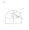
- Figures 2 and 3 are schematic diagrams showing the dome-type camera in a simplified manner.
- a dome-type camera 1 includes a lens unit 2 capable of rotating in a pan direction and a tilt direction, a dome cover 3 covering the lens unit 2, and a control unit 4 configured from a CPU, a microcontroller or the like.
- the lens unit 2 includes an image sensor 5 such as a CCD or a CMOS, a camera lens 6 arranged on the front side (on the left side in Figure 1 ) of the image sensor 5, and an aperture mechanism 7 arranged on the optical path of the camera lens 6. Also, although not shown in the drawing, the lens unit 2 includes a pan tilt mechanism for rotating the lens unit 2 in the pan direction and the tilt direction, and an offset mechanism for offsetting the lens unit 2 in the zenith direction of the dome cover 3.
- an image sensor 5 such as a CCD or a CMOS
- a camera lens 6 arranged on the front side (on the left side in Figure 1 ) of the image sensor 5
- an aperture mechanism 7 arranged on the optical path of the camera lens 6.
- the lens unit 2 includes a pan tilt mechanism for rotating the lens unit 2 in the pan direction and the tilt direction, and an offset mechanism for offsetting the lens unit 2 in the zenith direction of the dome cover 3.
- the dome cover 3 is attached to a base portion 8 while covering the lens unit 2.
- the dome cover 3 is made of transparent plastic such as polycarbonate, and has sufficient strength and light resistance.
- the form of the dome cover 3 is a hemisphere, and the center (the spherical center) of the dome cover 3 and the optical axis are coincident.
- the lens unit 2 is arranged at the center of the dome cover 3 (see Figure 2 ).
- the lens unit 2 is shifted from the center position of the dome cover 3 in the zenith direction (see Figure 3 ).
- the amount of shift (the amount of shift from the center position) is called the amount of offset.
- the angle of the camera lens 6 in the tilt direction is the angle formed by the horizontal direction of the dome cover 3 and the optical axis of the camera lens 6. Accordingly, when the lens unit 2 (the camera lens 6) is pointed in the horizontal direction, the tilt angle is 0 degrees, and when the lens unit 2 (the camera lens 6) is pointed in the zenith direction, the tilt angle is 90 degrees (see Figure 2 ).
- the control unit 4 includes an aperture control unit 9 for controlling the amount of aperture of the camera lens 6, a zoom control unit 10 for controlling the zoom factor of the camera lens 6, and an illuminance measurement unit 11 for measuring the illuminance of light entering the camera lens 6.
- the aperture control unit 9 serves the function of controlling the amount of aperture of the camera lens 6 by adjusting the amount of aperture of the aperture mechanism 7.
- the zoom control unit 10 serves the function of controlling the zoom factor of the camera lens 6 by moving the camera lens 6 to the front or the back along the optical axis direction.
- the illuminance measurement unit 11 serves the function of measuring illuminance based on an output signal from the image sensor 5.
- control unit 4 includes a tilt control unit 12 for controlling the rotation of the lens unit 2 in the tilt direction, and an offset control unit 13 for controlling the offset movement of the lens unit 2 in the zenith direction.
- the tilt control unit 12 serves the function of rotating the lens unit 2 in the tilt direction by controlling the pan tilt mechanism.
- the offset control unit 13 serves the function of offsetting the lens unit 2 in the zenith direction of the dome cover 3 by controlling the offset mechanism.
- control of the amount of aperture which is a characteristic operation of the dome-type camera 1 of the present embodiment will be described.
- Setting of the amount of aperture is performed based on three reference values (a first reference value, a second reference value and a third reference value).
- the first reference value for the amount of aperture is set based on the tilt angle of the lens unit 2 (the tilt angle of the camera lens 6).
- the tilt angle is detected by the tilt control unit 12.
- Figure 4 is a diagram showing a relationship between the tilt angle and the first reference value for the amount of aperture.
- the first reference value for the amount of aperture is set to become smaller from an open value (100%) toward a closed value (0%) as the tilt angle becomes smaller.
- the amount of aperture is set to 100% when the tilt angle is between 90 degrees and 45 degrees
- the amount of aperture is set to gradually decrease from 100% to 50% when the tilt angle is between 45 degrees and 0 degrees
- the amount of aperture is set to 50% when the tilt angle is smaller than 0 degrees.
- the amount of aperture decreases in a range where the tilt angle is between 45 degrees and 0 degrees, but the range of the tilt angle (the range of the tilt angle where the amount of aperture is decreased) is not limited thereto. Also, in the example in Figure 4 , a case is shown where the amount of aperture linearly (in a linear function manner) changes from 100% to 50% between 45 degrees and 0 degrees of the tilt angle, but the way the amount of aperture changes is not limited thereto.
- the second reference value for the amount of aperture is set based on the zoom factor of the camera lens 6.
- the zoom factor is detected by the zoom control unit 10.
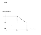
- Figure 5 is a diagram showing a relationship between the zoom factor and the second reference value for the amount of aperture.
- the second reference value for the amount of aperture is set to become smaller from an open value (100%) toward a closed value (0%) as the zoom factor increases.
- the amount of aperture is set to 100% when the zoom factor is between 1 and 9
- the amount of aperture is set to gradually decrease from 100% to 50% when the zoom factor is between 9 and 15, and the amount of aperture is set to 50% when the zoom factor is greater than 15.
- the amount of aperture decreases in a range where the zoom factor is between 1 and 9, but the range of the zoom factor (the range of the zoom factor where the amount of aperture is decreased) is not limited thereto. Also, in the example in Figure 5 , a case is shown where the amount of aperture linearly (in a linear function manner) changes from 100% to 50% when the zoom factor is between 1 and 9, but the way the amount of aperture changes is not limited thereto.
- the third reference value for the amount of aperture is set based on the illuminance of light entering the camera lens 6.
- the illuminance is measured by the illuminance measurement unit 11.
- Figure 6 is a diagram showing a relationship between the illuminance and the third reference value for the amount of aperture.
- the third reference value for the amount of aperture is set to become greater from a closed value (0%) toward an open value (100%) as the illuminance decreases.
- the amount of aperture is set to 50% when the illuminance is between 10 lux and 1 lux, and the amount of aperture is set to gradually increase from 50% to 100% when the illuminance is between 1 lux and 0.1 lux.
- the amount of aperture decreases in a range where the illuminance is between 1 lux and 0.1 lux, but the range of the illuminance (the range of the illuminance where the amount of aperture is decreased) is not limited thereto. Also, in the example in Figure 6 , a case is shown where the amount of aperture linearly (in a linear function manner) changes from 50% to 100% when the illuminance is between 1 lux and 0.1 lux, but the way the amount of aperture changes is not limited thereto.
- the amount of aperture is set based on the three reference values (the first reference value, the second reference value and the third reference value). Specifically, it is set to a greater value after comparing the third reference value with the smaller of the first reference value and the second reference value. For example, in the case that the first reference value is 75%, the second reference value is 50% and the third reference value is 90%, the third reference value (90%) is compared with the smaller of the first reference value and the second reference value (50%), and the amount of aperture is set to the greater (90%) of the values.
- the amount of aperture may be set based on two reference values (for example, the first reference value and the second reference value). In this case, it is set to a smaller value after comparing the first reference value with the second reference value. For example, in the case that the first reference value is 50% and the second reference value is 80%, the first reference value is compared with the second reference value, and the amount of aperture is set to the smaller (50%) of the values.
- the amount of aperture may be set based on one reference value (for example, based only on the first reference value).
- the amount of offset is set based on the tilt angle of the lens unit 2 (the tilt angle of the camera lens 6).
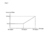
- Figure 7 is a diagram showing a relationship between the tilt angle and the amount of offset.
- the amount of offset is set to increase from the center position (0 mm) of the dome cover 3 toward the zenith direction as the tilt angle becomes smaller.
- the amount of offset is set to 0 mm when the tilt angle is between 90 degrees and 30 degrees, and the amount of offset is set to gradually increase from 0 mm to 30 mm when the tilt angle is between 30 degrees and -30 degrees.
- the amount of offset is increased in a range where the tilt angle is between 30 degrees and -30 degrees, but the range of the tilt angle (the range of the tilt angle where the amount of offset is decreased) is not limited thereto. Also, in the example in Figure 7 , a case is described where the amount of offset linearly (in a linear function manner) changes from 0 mm to 30 mm when the tilt angle is between 30 degrees and -30 degrees, but the way the amount of offset changes is not limited thereto.
- a desirable low tilt angle image with a reduced blur may be obtained even with a megapixel dome camera.
- the amount of aperture of the camera lens 6 is controlled to accordingly become small.
- the tilt angle becomes small
- the blur due to the unevenness in the thickness of the dome cover 3 becomes more noticeable, but in this case, the blur can be reduced by reducing the amount of aperture of the camera lens 6 and reducing the aberration. In this manner, a desirable low tilt angle image with a reduced blur may be obtained even with a megapixel dome camera.
- the amount of aperture of the camera lens 6 is controlled so as to accordingly become small.
- the zoom factor is increased, the blur due to the unevenness in the thickness of the dome cover 3 becomes more noticeable, but in this case, the blur can be reduced by reducing the amount of aperture of the camera lens 6 and reducing the aberration. In this manner, a desirable low tilt angle image with a reduced blur may be obtained even with a megapixel dome camera.
- the amount of aperture of the camera lens 6 is set to the smaller of the first reference value set based on the tilt angle and the second reference value set based on the zoom factor, the amount of aperture can be prevented from becoming excessively small.
- the amount of aperture of the camera lens 6 is controlled so as to accordingly become great.
- the amount of aperture can thereby be prevented from becoming excessively small. Accordingly, a high-sensitivity image can be obtained even in a low-illumination image-capturing environment (a dark image-capturing environment) .
- the angle of the camera lens 6 of the dome-type camera 1 in the tilt direction becomes small
- the amount of aperture is set to a smaller value of the first reference value and the second reference value, but in the case a negative impact on the tilt angle of the dome cover and the resolution at the zoom factor of the zoom lens is great, the amount of aperture may be set to the greater of the first reference value and the second reference value.
- the dome-type camera according to the present invention is useful as a surveillance camera or the like in that an effect is achieved that a desirable low tilt angle image with a reduced blur may be obtained even with a megapixel dome camera.
Landscapes
- Engineering & Computer Science (AREA)
- Multimedia (AREA)
- Signal Processing (AREA)
- Physics & Mathematics (AREA)
- General Physics & Mathematics (AREA)
- Studio Devices (AREA)
- Accessories Of Cameras (AREA)
- Exposure Control For Cameras (AREA)
Applications Claiming Priority (2)
| Application Number | Priority Date | Filing Date | Title |
|---|---|---|---|
| JP2010228306A JP5834170B2 (ja) | 2010-10-08 | 2010-10-08 | ドーム型カメラおよび絞り制御方法 |
| PCT/JP2011/005275 WO2012046398A1 (ja) | 2010-10-08 | 2011-09-20 | ドーム型カメラおよび絞り制御方法 |
Publications (3)
| Publication Number | Publication Date |
|---|---|
| EP2605063A1 EP2605063A1 (en) | 2013-06-19 |
| EP2605063A4 EP2605063A4 (en) | 2013-09-25 |
| EP2605063B1 true EP2605063B1 (en) | 2015-04-01 |
Family
ID=45927406
Family Applications (1)
| Application Number | Title | Priority Date | Filing Date |
|---|---|---|---|
| EP11830332.0A Not-in-force EP2605063B1 (en) | 2010-10-08 | 2011-09-20 | Dome-type camera and aperture control method |
Country Status (5)
| Country | Link |
|---|---|
| US (1) | US9014549B2 (enExample) |
| EP (1) | EP2605063B1 (enExample) |
| JP (1) | JP5834170B2 (enExample) |
| CN (1) | CN203241687U (enExample) |
| WO (1) | WO2012046398A1 (enExample) |
Families Citing this family (7)
| Publication number | Priority date | Publication date | Assignee | Title |
|---|---|---|---|---|
| US9291880B2 (en) * | 2013-01-30 | 2016-03-22 | Spark Facter Design | Mobile device light meter attachment |
| JP6283909B2 (ja) * | 2013-03-01 | 2018-02-28 | パナソニックIpマネジメント株式会社 | カメラ装置及びカメラ装置の制御方法 |
| JP6211417B2 (ja) | 2013-12-27 | 2017-10-11 | 株式会社エーエスシー | 監視カメラ装置 |
| JP2015180044A (ja) * | 2014-02-28 | 2015-10-08 | パナソニックIpマネジメント株式会社 | ドームカメラ |
| JP6468744B2 (ja) | 2014-07-23 | 2019-02-13 | キヤノン株式会社 | 撮像装置、画像処理装置、撮像装置の画像処理方法、並びにプログラム |
| US10044932B2 (en) * | 2015-03-13 | 2018-08-07 | Sensormatic Electronics, LLC | Wide angle fisheye security camera having offset lens and image sensor |
| JP6080065B1 (ja) * | 2016-03-07 | 2017-02-15 | パナソニックIpマネジメント株式会社 | カメラ装置 |
Family Cites Families (15)
| Publication number | Priority date | Publication date | Assignee | Title |
|---|---|---|---|---|
| US4833534A (en) * | 1988-02-19 | 1989-05-23 | Sensormatic Electronics Corporation | Surveillance assembly having enhanced shielding and reduced size |
| JP3610113B2 (ja) * | 1995-03-17 | 2005-01-12 | キヤノン株式会社 | 撮像装置 |
| US6707500B1 (en) | 1995-03-17 | 2004-03-16 | Canon Kabushiki Kaisha | Image pickup apparatus with correction of held exposure parameters and lens spherical aberration correction |
| JPH0983841A (ja) * | 1995-09-06 | 1997-03-28 | Nisca Corp | テレビカメラ用の雲台構造、及び、パンチルトカメラ |
| JP2004320526A (ja) * | 2003-04-17 | 2004-11-11 | Minolta Co Ltd | 撮像装置、撮像システム、及びプログラム |
| JP4284208B2 (ja) * | 2004-02-23 | 2009-06-24 | パナソニック株式会社 | チルト式カメラ装置 |
| JP4284223B2 (ja) * | 2004-04-07 | 2009-06-24 | パナソニック株式会社 | ドーム型カメラおよびドームカバー |
| KR100760544B1 (ko) * | 2005-04-18 | 2007-09-20 | 엘지전자 주식회사 | 기계적 조리개 및 셔터를 구비한 초소형 카메라 모듈 |
| JP4979285B2 (ja) * | 2006-07-07 | 2012-07-18 | パナソニック株式会社 | ドーム型監視カメラ装置 |
| JP2009003010A (ja) * | 2007-06-19 | 2009-01-08 | Canon Inc | 雲台式カメラ装置 |
| JP4845931B2 (ja) * | 2008-06-13 | 2011-12-28 | 三菱電機株式会社 | ドーム型カメラ及びドームカバーの製造方法 |
| JP2010008498A (ja) * | 2008-06-24 | 2010-01-14 | Canon Inc | 撮像装置 |
| JP5307474B2 (ja) * | 2008-08-19 | 2013-10-02 | オリンパス株式会社 | 顕微鏡対物レンズおよび拡大撮像装置 |
| JP5223597B2 (ja) * | 2008-10-30 | 2013-06-26 | 株式会社Jvcケンウッド | 監視カメラ装置のチルト機構 |
| JP5431293B2 (ja) * | 2010-11-10 | 2014-03-05 | パナソニック株式会社 | ドーム型カメラ |
-
2010
- 2010-10-08 JP JP2010228306A patent/JP5834170B2/ja active Active
-
2011
- 2011-09-20 CN CN2011900007782U patent/CN203241687U/zh not_active Expired - Fee Related
- 2011-09-20 US US13/821,336 patent/US9014549B2/en active Active
- 2011-09-20 WO PCT/JP2011/005275 patent/WO2012046398A1/ja not_active Ceased
- 2011-09-20 EP EP11830332.0A patent/EP2605063B1/en not_active Not-in-force
Also Published As
| Publication number | Publication date |
|---|---|
| EP2605063A1 (en) | 2013-06-19 |
| JP5834170B2 (ja) | 2015-12-16 |
| WO2012046398A1 (ja) | 2012-04-12 |
| US20130272690A1 (en) | 2013-10-17 |
| JP2012083464A (ja) | 2012-04-26 |
| CN203241687U (zh) | 2013-10-16 |
| US9014549B2 (en) | 2015-04-21 |
| EP2605063A4 (en) | 2013-09-25 |
Similar Documents
| Publication | Publication Date | Title |
|---|---|---|
| EP2605063B1 (en) | Dome-type camera and aperture control method | |
| US8899849B2 (en) | Camera apparatus and method of controlling camera apparatus | |
| US8218039B2 (en) | Electronic camera and control program of same | |
| US10136064B2 (en) | Image processing apparatus and method of controlling image processing apparatus | |
| JP5541016B2 (ja) | 撮像システムおよび画素信号読出し方法 | |
| US10694109B2 (en) | Imaging apparatus | |
| US11146734B2 (en) | Image capturing apparatus and image monitoring system | |
| WO2014171304A1 (ja) | 撮像装置、撮像装置駆動方法、撮像装置制御プログラム | |
| US20150070561A1 (en) | Transmitted light volume adjusting apparatus and transmitted light volume adjusting method | |
| JP6463190B2 (ja) | 撮像装置及びその制御方法並びにプログラム | |
| JP2014021491A (ja) | レンズ手ブレ補正システム及びその方法 | |
| CN102244727B (zh) | 摄像设备 | |
| JP6910841B2 (ja) | 撮像装置及びその調整方法 | |
| US8264550B2 (en) | Shake correction apparatus, image pickup apparatus, and method for controlling shake correction apparatus | |
| JP7352891B2 (ja) | 撮像装置 | |
| WO2009067121A1 (en) | Camera sensor system self-calibration | |
| JP2005148265A (ja) | カメラ装置 | |
| JP4229053B2 (ja) | 撮像装置、撮像方法及び撮像処理のためのプログラム | |
| JP2009031337A (ja) | 映像表示装置 | |
| JP2012244243A (ja) | 撮像装置および撮像装置の制御方法 | |
| JP5384173B2 (ja) | オートフォーカスシステム | |
| JP2017044816A (ja) | 撮像装置、その制御方法およびプログラム | |
| JP2005136859A (ja) | 撮像装置 | |
| KR20140124431A (ko) | 촬영 장치의 제어 방법 | |
| JP2020056854A (ja) | 撮像システムにおける防振時の絞り制御手段 |
Legal Events
| Date | Code | Title | Description |
|---|---|---|---|
| PUAI | Public reference made under article 153(3) epc to a published international application that has entered the european phase |
Free format text: ORIGINAL CODE: 0009012 |
|
| 17P | Request for examination filed |
Effective date: 20130313 |
|
| AK | Designated contracting states |
Kind code of ref document: A1 Designated state(s): AL AT BE BG CH CY CZ DE DK EE ES FI FR GB GR HR HU IE IS IT LI LT LU LV MC MK MT NL NO PL PT RO RS SE SI SK SM TR |
|
| A4 | Supplementary search report drawn up and despatched |
Effective date: 20130828 |
|
| RIC1 | Information provided on ipc code assigned before grant |
Ipc: G03B 17/56 20060101AFI20130822BHEP Ipc: H04N 5/238 20060101ALI20130822BHEP Ipc: G03B 17/00 20060101ALI20130822BHEP Ipc: G03B 7/095 20060101ALI20130822BHEP Ipc: G08B 13/196 20060101ALI20130822BHEP Ipc: G03B 15/00 20060101ALI20130822BHEP Ipc: H04N 5/225 20060101ALI20130822BHEP Ipc: H04N 5/232 20060101ALI20130822BHEP |
|
| DAX | Request for extension of the european patent (deleted) | ||
| 17Q | First examination report despatched |
Effective date: 20140513 |
|
| GRAP | Despatch of communication of intention to grant a patent |
Free format text: ORIGINAL CODE: EPIDOSNIGR1 |
|
| INTG | Intention to grant announced |
Effective date: 20141027 |
|
| GRAS | Grant fee paid |
Free format text: ORIGINAL CODE: EPIDOSNIGR3 |
|
| GRAA | (expected) grant |
Free format text: ORIGINAL CODE: 0009210 |
|
| AK | Designated contracting states |
Kind code of ref document: B1 Designated state(s): AL AT BE BG CH CY CZ DE DK EE ES FI FR GB GR HR HU IE IS IT LI LT LU LV MC MK MT NL NO PL PT RO RS SE SI SK SM TR |
|
| REG | Reference to a national code |
Ref country code: GB Ref legal event code: FG4D |
|
| REG | Reference to a national code |
Ref country code: CH Ref legal event code: EP |
|
| REG | Reference to a national code |
Ref country code: IE Ref legal event code: FG4D |
|
| REG | Reference to a national code |
Ref country code: DE Ref legal event code: R096 Ref document number: 602011015342 Country of ref document: DE Effective date: 20150513 |
|
| REG | Reference to a national code |
Ref country code: AT Ref legal event code: REF Ref document number: 719414 Country of ref document: AT Kind code of ref document: T Effective date: 20150515 |
|
| REG | Reference to a national code |
Ref country code: NL Ref legal event code: VDEP Effective date: 20150401 |
|
| REG | Reference to a national code |
Ref country code: AT Ref legal event code: MK05 Ref document number: 719414 Country of ref document: AT Kind code of ref document: T Effective date: 20150401 |
|
| REG | Reference to a national code |
Ref country code: LT Ref legal event code: MG4D |
|
| PG25 | Lapsed in a contracting state [announced via postgrant information from national office to epo] |
Ref country code: NL Free format text: LAPSE BECAUSE OF FAILURE TO SUBMIT A TRANSLATION OF THE DESCRIPTION OR TO PAY THE FEE WITHIN THE PRESCRIBED TIME-LIMIT Effective date: 20150401 |
|
| PG25 | Lapsed in a contracting state [announced via postgrant information from national office to epo] |
Ref country code: FI Free format text: LAPSE BECAUSE OF FAILURE TO SUBMIT A TRANSLATION OF THE DESCRIPTION OR TO PAY THE FEE WITHIN THE PRESCRIBED TIME-LIMIT Effective date: 20150401 Ref country code: NO Free format text: LAPSE BECAUSE OF FAILURE TO SUBMIT A TRANSLATION OF THE DESCRIPTION OR TO PAY THE FEE WITHIN THE PRESCRIBED TIME-LIMIT Effective date: 20150701 Ref country code: HR Free format text: LAPSE BECAUSE OF FAILURE TO SUBMIT A TRANSLATION OF THE DESCRIPTION OR TO PAY THE FEE WITHIN THE PRESCRIBED TIME-LIMIT Effective date: 20150401 Ref country code: LT Free format text: LAPSE BECAUSE OF FAILURE TO SUBMIT A TRANSLATION OF THE DESCRIPTION OR TO PAY THE FEE WITHIN THE PRESCRIBED TIME-LIMIT Effective date: 20150401 Ref country code: CZ Free format text: LAPSE BECAUSE OF FAILURE TO SUBMIT A TRANSLATION OF THE DESCRIPTION OR TO PAY THE FEE WITHIN THE PRESCRIBED TIME-LIMIT Effective date: 20150401 Ref country code: PT Free format text: LAPSE BECAUSE OF FAILURE TO SUBMIT A TRANSLATION OF THE DESCRIPTION OR TO PAY THE FEE WITHIN THE PRESCRIBED TIME-LIMIT Effective date: 20150803 Ref country code: ES Free format text: LAPSE BECAUSE OF FAILURE TO SUBMIT A TRANSLATION OF THE DESCRIPTION OR TO PAY THE FEE WITHIN THE PRESCRIBED TIME-LIMIT Effective date: 20150401 |
|
| PG25 | Lapsed in a contracting state [announced via postgrant information from national office to epo] |
Ref country code: GR Free format text: LAPSE BECAUSE OF FAILURE TO SUBMIT A TRANSLATION OF THE DESCRIPTION OR TO PAY THE FEE WITHIN THE PRESCRIBED TIME-LIMIT Effective date: 20150702 Ref country code: RS Free format text: LAPSE BECAUSE OF FAILURE TO SUBMIT A TRANSLATION OF THE DESCRIPTION OR TO PAY THE FEE WITHIN THE PRESCRIBED TIME-LIMIT Effective date: 20150401 Ref country code: LV Free format text: LAPSE BECAUSE OF FAILURE TO SUBMIT A TRANSLATION OF THE DESCRIPTION OR TO PAY THE FEE WITHIN THE PRESCRIBED TIME-LIMIT Effective date: 20150401 Ref country code: IS Free format text: LAPSE BECAUSE OF FAILURE TO SUBMIT A TRANSLATION OF THE DESCRIPTION OR TO PAY THE FEE WITHIN THE PRESCRIBED TIME-LIMIT Effective date: 20150801 Ref country code: AT Free format text: LAPSE BECAUSE OF FAILURE TO SUBMIT A TRANSLATION OF THE DESCRIPTION OR TO PAY THE FEE WITHIN THE PRESCRIBED TIME-LIMIT Effective date: 20150401 |
|
| REG | Reference to a national code |
Ref country code: DE Ref legal event code: R097 Ref document number: 602011015342 Country of ref document: DE |
|
| REG | Reference to a national code |
Ref country code: DE Ref legal event code: R084 Ref document number: 602011015342 Country of ref document: DE |
|
| PG25 | Lapsed in a contracting state [announced via postgrant information from national office to epo] |
Ref country code: EE Free format text: LAPSE BECAUSE OF FAILURE TO SUBMIT A TRANSLATION OF THE DESCRIPTION OR TO PAY THE FEE WITHIN THE PRESCRIBED TIME-LIMIT Effective date: 20150401 Ref country code: DK Free format text: LAPSE BECAUSE OF FAILURE TO SUBMIT A TRANSLATION OF THE DESCRIPTION OR TO PAY THE FEE WITHIN THE PRESCRIBED TIME-LIMIT Effective date: 20150401 |
|
| PLBE | No opposition filed within time limit |
Free format text: ORIGINAL CODE: 0009261 |
|
| STAA | Information on the status of an ep patent application or granted ep patent |
Free format text: STATUS: NO OPPOSITION FILED WITHIN TIME LIMIT |
|
| REG | Reference to a national code |
Ref country code: GB Ref legal event code: 746 Effective date: 20160120 |
|
| PG25 | Lapsed in a contracting state [announced via postgrant information from national office to epo] |
Ref country code: RO Free format text: LAPSE BECAUSE OF NON-PAYMENT OF DUE FEES Effective date: 20150401 Ref country code: PL Free format text: LAPSE BECAUSE OF FAILURE TO SUBMIT A TRANSLATION OF THE DESCRIPTION OR TO PAY THE FEE WITHIN THE PRESCRIBED TIME-LIMIT Effective date: 20150401 Ref country code: SK Free format text: LAPSE BECAUSE OF FAILURE TO SUBMIT A TRANSLATION OF THE DESCRIPTION OR TO PAY THE FEE WITHIN THE PRESCRIBED TIME-LIMIT Effective date: 20150401 |
|
| 26N | No opposition filed |
Effective date: 20160105 |
|
| PG25 | Lapsed in a contracting state [announced via postgrant information from national office to epo] |
Ref country code: MC Free format text: LAPSE BECAUSE OF FAILURE TO SUBMIT A TRANSLATION OF THE DESCRIPTION OR TO PAY THE FEE WITHIN THE PRESCRIBED TIME-LIMIT Effective date: 20150401 Ref country code: LU Free format text: LAPSE BECAUSE OF FAILURE TO SUBMIT A TRANSLATION OF THE DESCRIPTION OR TO PAY THE FEE WITHIN THE PRESCRIBED TIME-LIMIT Effective date: 20150920 Ref country code: IT Free format text: LAPSE BECAUSE OF FAILURE TO SUBMIT A TRANSLATION OF THE DESCRIPTION OR TO PAY THE FEE WITHIN THE PRESCRIBED TIME-LIMIT Effective date: 20150401 |
|
| REG | Reference to a national code |
Ref country code: CH Ref legal event code: PL |
|
| PG25 | Lapsed in a contracting state [announced via postgrant information from national office to epo] |
Ref country code: SI Free format text: LAPSE BECAUSE OF FAILURE TO SUBMIT A TRANSLATION OF THE DESCRIPTION OR TO PAY THE FEE WITHIN THE PRESCRIBED TIME-LIMIT Effective date: 20150401 |
|
| REG | Reference to a national code |
Ref country code: IE Ref legal event code: MM4A |
|
| REG | Reference to a national code |
Ref country code: FR Ref legal event code: ST Effective date: 20160531 |
|
| PG25 | Lapsed in a contracting state [announced via postgrant information from national office to epo] |
Ref country code: IE Free format text: LAPSE BECAUSE OF NON-PAYMENT OF DUE FEES Effective date: 20150920 Ref country code: LI Free format text: LAPSE BECAUSE OF NON-PAYMENT OF DUE FEES Effective date: 20150930 Ref country code: CH Free format text: LAPSE BECAUSE OF NON-PAYMENT OF DUE FEES Effective date: 20150930 |
|
| PG25 | Lapsed in a contracting state [announced via postgrant information from national office to epo] |
Ref country code: BE Free format text: LAPSE BECAUSE OF FAILURE TO SUBMIT A TRANSLATION OF THE DESCRIPTION OR TO PAY THE FEE WITHIN THE PRESCRIBED TIME-LIMIT Effective date: 20150401 Ref country code: FR Free format text: LAPSE BECAUSE OF NON-PAYMENT OF DUE FEES Effective date: 20150930 |
|
| PG25 | Lapsed in a contracting state [announced via postgrant information from national office to epo] |
Ref country code: MT Free format text: LAPSE BECAUSE OF FAILURE TO SUBMIT A TRANSLATION OF THE DESCRIPTION OR TO PAY THE FEE WITHIN THE PRESCRIBED TIME-LIMIT Effective date: 20150401 |
|
| PG25 | Lapsed in a contracting state [announced via postgrant information from national office to epo] |
Ref country code: SM Free format text: LAPSE BECAUSE OF FAILURE TO SUBMIT A TRANSLATION OF THE DESCRIPTION OR TO PAY THE FEE WITHIN THE PRESCRIBED TIME-LIMIT Effective date: 20150401 Ref country code: HU Free format text: LAPSE BECAUSE OF FAILURE TO SUBMIT A TRANSLATION OF THE DESCRIPTION OR TO PAY THE FEE WITHIN THE PRESCRIBED TIME-LIMIT; INVALID AB INITIO Effective date: 20110920 Ref country code: BG Free format text: LAPSE BECAUSE OF FAILURE TO SUBMIT A TRANSLATION OF THE DESCRIPTION OR TO PAY THE FEE WITHIN THE PRESCRIBED TIME-LIMIT Effective date: 20150401 |
|
| PG25 | Lapsed in a contracting state [announced via postgrant information from national office to epo] |
Ref country code: SE Free format text: LAPSE BECAUSE OF FAILURE TO SUBMIT A TRANSLATION OF THE DESCRIPTION OR TO PAY THE FEE WITHIN THE PRESCRIBED TIME-LIMIT Effective date: 20150401 Ref country code: CY Free format text: LAPSE BECAUSE OF FAILURE TO SUBMIT A TRANSLATION OF THE DESCRIPTION OR TO PAY THE FEE WITHIN THE PRESCRIBED TIME-LIMIT Effective date: 20150401 |
|
| PG25 | Lapsed in a contracting state [announced via postgrant information from national office to epo] |
Ref country code: MK Free format text: LAPSE BECAUSE OF FAILURE TO SUBMIT A TRANSLATION OF THE DESCRIPTION OR TO PAY THE FEE WITHIN THE PRESCRIBED TIME-LIMIT Effective date: 20150401 Ref country code: TR Free format text: LAPSE BECAUSE OF FAILURE TO SUBMIT A TRANSLATION OF THE DESCRIPTION OR TO PAY THE FEE WITHIN THE PRESCRIBED TIME-LIMIT Effective date: 20150401 |
|
| PG25 | Lapsed in a contracting state [announced via postgrant information from national office to epo] |
Ref country code: AL Free format text: LAPSE BECAUSE OF FAILURE TO SUBMIT A TRANSLATION OF THE DESCRIPTION OR TO PAY THE FEE WITHIN THE PRESCRIBED TIME-LIMIT Effective date: 20150401 |
|
| REG | Reference to a national code |
Ref country code: DE Ref legal event code: R082 Ref document number: 602011015342 Country of ref document: DE Representative=s name: DENNEMEYER & ASSOCIATES S.A., DE Ref country code: DE Ref legal event code: R081 Ref document number: 602011015342 Country of ref document: DE Owner name: PANASONIC I-PRO SENSING SOLUTIONS CO., LTD., JP Free format text: FORMER OWNER: PANASONIC CORPORATION, KADOMA-SHI, OSAKA, JP |
|
| REG | Reference to a national code |
Ref country code: GB Ref legal event code: 732E Free format text: REGISTERED BETWEEN 20200109 AND 20200115 |
|
| REG | Reference to a national code |
Ref country code: DE Ref legal event code: R082 Ref document number: 602011015342 Country of ref document: DE Representative=s name: DENNEMEYER & ASSOCIATES S.A., DE Ref country code: DE Ref legal event code: R081 Ref document number: 602011015342 Country of ref document: DE Owner name: PANASONIC I-PRO SENSING SOLUTIONS CO., LTD., JP Free format text: FORMER OWNER: PANASONIC I-PRO SENSING SOLUTIONS CO., LTD., FUKUOKA, JP |
|
| REG | Reference to a national code |
Ref country code: GB Ref legal event code: 732E Free format text: REGISTERED BETWEEN 20210304 AND 20210310 |
|
| PGFP | Annual fee paid to national office [announced via postgrant information from national office to epo] |
Ref country code: DE Payment date: 20210810 Year of fee payment: 11 Ref country code: GB Payment date: 20210811 Year of fee payment: 11 |
|
| REG | Reference to a national code |
Ref country code: DE Ref legal event code: R119 Ref document number: 602011015342 Country of ref document: DE |
|
| GBPC | Gb: european patent ceased through non-payment of renewal fee |
Effective date: 20220920 |
|
| PG25 | Lapsed in a contracting state [announced via postgrant information from national office to epo] |
Ref country code: DE Free format text: LAPSE BECAUSE OF NON-PAYMENT OF DUE FEES Effective date: 20230401 |
|
| PG25 | Lapsed in a contracting state [announced via postgrant information from national office to epo] |
Ref country code: GB Free format text: LAPSE BECAUSE OF NON-PAYMENT OF DUE FEES Effective date: 20220920 |