EP2602647A1 - Polariseur réfléchissant à nombre réduit de couches et à gain optimisé - Google Patents
Polariseur réfléchissant à nombre réduit de couches et à gain optimisé Download PDFInfo
- Publication number
- EP2602647A1 EP2602647A1 EP13158137.3A EP13158137A EP2602647A1 EP 2602647 A1 EP2602647 A1 EP 2602647A1 EP 13158137 A EP13158137 A EP 13158137A EP 2602647 A1 EP2602647 A1 EP 2602647A1
- Authority
- EP
- European Patent Office
- Prior art keywords
- axis
- reflectivity
- polarizer
- microlayers
- light
- Prior art date
- Legal status (The legal status is an assumption and is not a legal conclusion. Google has not performed a legal analysis and makes no representation as to the accuracy of the status listed.)
- Withdrawn
Links
Images

Classifications
-
- G—PHYSICS
- G02—OPTICS
- G02B—OPTICAL ELEMENTS, SYSTEMS OR APPARATUS
- G02B5/00—Optical elements other than lenses
- G02B5/30—Polarising elements
- G02B5/3025—Polarisers, i.e. arrangements capable of producing a definite output polarisation state from an unpolarised input state
- G02B5/3066—Polarisers, i.e. arrangements capable of producing a definite output polarisation state from an unpolarised input state involving the reflection of light at a particular angle of incidence, e.g. Brewster's angle
-
- G—PHYSICS
- G02—OPTICS
- G02B—OPTICAL ELEMENTS, SYSTEMS OR APPARATUS
- G02B27/00—Optical systems or apparatus not provided for by any of the groups G02B1/00 - G02B26/00, G02B30/00
- G02B27/28—Optical systems or apparatus not provided for by any of the groups G02B1/00 - G02B26/00, G02B30/00 for polarising
- G02B27/283—Optical systems or apparatus not provided for by any of the groups G02B1/00 - G02B26/00, G02B30/00 for polarising used for beam splitting or combining
-
- G—PHYSICS
- G02—OPTICS
- G02B—OPTICAL ELEMENTS, SYSTEMS OR APPARATUS
- G02B5/00—Optical elements other than lenses
- G02B5/30—Polarising elements
- G02B5/3025—Polarisers, i.e. arrangements capable of producing a definite output polarisation state from an unpolarised input state
- G02B5/3033—Polarisers, i.e. arrangements capable of producing a definite output polarisation state from an unpolarised input state in the form of a thin sheet or foil, e.g. Polaroid
- G02B5/3041—Polarisers, i.e. arrangements capable of producing a definite output polarisation state from an unpolarised input state in the form of a thin sheet or foil, e.g. Polaroid comprising multiple thin layers, e.g. multilayer stacks
- G02B5/305—Polarisers, i.e. arrangements capable of producing a definite output polarisation state from an unpolarised input state in the form of a thin sheet or foil, e.g. Polaroid comprising multiple thin layers, e.g. multilayer stacks including organic materials, e.g. polymeric layers
-
- G—PHYSICS
- G02—OPTICS
- G02B—OPTICAL ELEMENTS, SYSTEMS OR APPARATUS
- G02B5/00—Optical elements other than lenses
- G02B5/30—Polarising elements
- G02B5/3083—Birefringent or phase retarding elements
Definitions
- This invention relates generally to multilayer optical films, with particular application to such films configured as polarizers that are suitable for use in backlights for visual display systems.
- Multilayer optical films i.e., films that provide desirable transmission and/or reflection properties at least partially by an arrangement of microlayers of differing refractive index. It has been known to make such multilayer optical films by depositing a sequence of inorganic materials in optically thin layers ("microlayers") on a substrate in a vacuum chamber. Inorganic multilayer optical films are described, for example, in textbooks by H. A. Macleod, Thin-Film Optical Filters, 2nd Ed., Macmillan Publishing Co. (1986 ) and by A. Thelan, Design of Optical Interference Filters, McGraw-Hill, Inc. (1989 ).
- Multilayer optical films have also been demonstrated by coextrusion of alternating polymer layers. See, e.g., U.S. Patents 3,610,729 (Rogers ), 4,446,305 (Rogers et al. ), 4,540,623 (Im et al. ), 5,448,404 (Schrenk et al. ), and 5,882,774 (Jonza et al. ).
- polymer materials are used predominantly or exclusively in the makeup of the individual layers. Such films are compatible with high volume manufacturing processes and can be made in large sheets and roll goods.
- a multilayer optical film includes individual microlayers having different refractive index characteristics so that some light is reflected at interfaces between adjacent microlayers.
- the microlayers are sufficiently thin so that light reflected at a plurality of the interfaces undergoes constructive or destructive interference in order to give the multilayer optical film the desired reflective or transmissive properties.
- each microlayer For multilayer optical films designed to reflect light at ultraviolet, visible, or near-infrared wavelengths, each microlayer generally has an optical thickness (a physical thickness multiplied by refractive index) of less than about 1 ⁇ m.
- Thicker layers are also typically included, such as skin layers at the outer surfaces of the multilayer optical film, or protective boundary layers (PBLs) disposed within the multilayer optical films, that separate coherent groupings (referred to herein as "packets") of microlayers.
- PBLs protective boundary layers
- birefringent polymers for polarizing applications, e.g., reflective polarizers, at least some of the optical layers are formed using birefringent polymers, in which the polymer's index of refraction has differing values along orthogonal Cartesian axes of the polymer.
- birefringent polymer microlayers have their orthogonal Cartesian axes defined by the normal to the layer plane (z-axis), with the x-axis and y-axis lying within the layer plane. Birefringent polymers can also be used in non-polarizing applications.
- Other layer arrangements such as multilayer optical films having 2-microlayer optical repeat units whose f-ratio is different from 50%, or films whose optical repeat units include more than two microlayers, are also known.
- These optical repeat unit designs can be configured to reduce or to increase certain higher-order reflections. See , e.g., U.S. Patent Nos.
- Thickness gradients along a thickness axis of the film can be used to provide a widened reflection band, such as a reflection band that extends over the entire human visible region and into the near infrared so that as the band shifts to shorter wavelengths at oblique incidence angles the microlayer stack continues to reflect over the entire visible spectrum.
- Thickness gradients tailored to sharpen band edges, i.e., the wavelength transition between high reflection and high transmission, are discussed in U.S. Patent 6,157,490 (Wheatley et al. ).
- multilayer optical films and related designs and constructions are discussed in U.S. Patents 5,882,774 (Jonza et al. ) and 6,531,230 (Weber et al. ), PCT Publications WO 95/17303 (Ouderkirk et al. ) and WO 99/39224 (Ouderkirk et al. ), and the publication entitled " Giant Birefringent Optics in Multilayer Polymer Mirrors", Science, Vol. 287, March 2000 (Weber et al.).
- the multilayer optical films and related articles can include additional layers and coatings selected for their optical, mechanical, and/or chemical properties.
- a UV absorbing layer can be added at the incident side of the film to protect components from degradation caused by UV light.
- the multilayer optical films can be attached to mechanically reinforcing layers using a UV-curable acrylate adhesive or other suitable material.
- Such reinforcing layers may comprise polymers such as PET or polycarbonate, and may also include structured surfaces that provide optical function such as light diffusion or collimation, e.g. by the use of beads or prisms. Additional layers and coatings can also include scratch resistant layers, tear resistant layers, and stiffening agents. See e.g. U.S. Patent 6,368,699 (Gilbert et al. ). Methods and devices for making multilayer optical films are discussed in U.S. Patent 6,783,349 (Neavin et al. ).
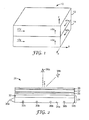
- FIG. 1 depicts one layer pair of a multilayer optical film 10.
- the film 10 includes a large number of alternating microlayers 12, 14, only two of which are shown for simplicity.
- the microlayers have different refractive index characteristics so that some light is reflected at the interfaces between adjacent microlayers.
- the microlayers are thin enough so that light reflected at a plurality of the interfaces undergoes constructive or destructive interference to give the film the desired reflective or transmissive properties.
- each microlayer generally has an optical thickness (i.e., a physical thickness multiplied by refractive index) of less than about 1 ⁇ m.
- Thicker layers are also typically included, such as skin layers at the outer surfaces of the film, or protective boundary layers disposed within the film that separate packets of microlayers.
- the reflective and transmissive properties of multilayer optical film 10 are a function of the refractive indices of the respective microlayers and the thicknesses and thickness distribution of the microlayers.
- Each microlayer can be characterized at least in localized positions in the film by in-plane refractive indices n x , n y , and a refractive index n z associated with a thickness axis of the film. These indices represent the refractive index of the subject material for light polarized along mutually orthogonal x-, y-, and z-axes, respectively.
- n1x, n1y, n1z for layer 12 these indices are labeled n1x, n1y, n1z for layer 12, and n2x, n2y, n2z for layer 14, their respective layer-to-layer differences being ⁇ n x , ⁇ n y , ⁇ n z .
- the x-, y-, and z- axes are assumed to be local Cartesian coordinates applicable to any point of interest on a multilayer optical film, in which the microlayers extend parallel to the x-y plane, and wherein the x-axis is oriented within the plane of the film to maximize the magnitude of ⁇ n x .
- the magnitude of ⁇ n y can be equal to or less than-but not greater than-the magnitude of ⁇ n x .
- the selection of which material layer to begin with in calculating the differences ⁇ n x , ⁇ n y , ⁇ n z is dictated by requiring that ⁇ n x be non-negative.
- Film 10 is made by co-extrusion of a large number, e.g. tens or hundreds of layers of two alternating polymers A, B, typically followed by passing the multilayer extrudate through one or more multiplication die, and then stretching or otherwise orienting the extrudate to form a final film.
- the resulting film is typically composed of many hundreds of individual microlayers whose thicknesses and refractive indices are tailored to provide one or more reflection bands in desired region(s) of the spectrum, such as in the visible or near infrared.
- adjacent microlayers typically exhibit a difference in refractive index ( ⁇ n x ) for light polarized along the x-axis of at least 0.05. If the high reflectivity is desired for two orthogonal polarizations, then the adjacent microlayers also can be made to exhibit a difference in refractive index (Any) for light polarized along the y-axis of at least 0.05.
- the '774 (Jonza et al.) patent referenced above describes, among other things, how the refractive index difference ( ⁇ n z ) between adjacent microlayers for light polarized along the z-axis can be tailored to achieve desirable reflectivity properties for the p-polarization component of obliquely incident light.
- the z-index mismatch ⁇ n z between microlayers can be controlled to be substantially less than the maximum in-plane refractive index difference ⁇ n x , such that ⁇ n z ⁇ 0.5* ⁇ n x , or ⁇ n z ⁇ 0.25 * ⁇ n x .
- a zero or near zero magnitude z-index mismatch yields interfaces between microlayers whose reflectivity for p-polarized light is constant or near constant as a function of incidence angle.
- the z-index mismatch ⁇ n z can be controlled to have the opposite polarity compared to the in-plane index difference ⁇ n x , i.e. ⁇ n z ⁇ 0. This condition yields interfaces whose reflectivity for p-polarized light increases with increasing angles of incidence, as is the case for s-polarized light.
- the '774 (Jonza et al.) patent also discusses certain design considerations relating to multilayer optical films configured as polarizers, referred to as multilayer reflecting or reflective polarizers.
- the ideal reflecting polarizer has high reflectance along one axis (the "extinction” or “block” axis, corresponding to the x-direction) and zero reflectance along the other axis (the “transmission” or “pass” axis, corresponding to the y-direction). If some reflectivity occurs along the transmission axis, the efficiency of the polarizer at off-normal angles may be reduced, and if the reflectivity is different for various wavelengths, color may be introduced into the transmitted light.
- Reflective polarizers are often used in visual display systems such as liquid crystal displays. These systems-now found in a wide variety of electronic devices such as mobile phones, computers, and some flat panel TVs-use a liquid crystal (LC) panel illuminated from behind with an extended area backlight.
- the reflective polarizer is placed over or otherwise incorporated into the backlight to transmit light of a polarization state useable by the LC panel from the backlight to the LC panel.
- a representative visual display system 20 is shown in schematic side view in FIG. 2 .
- the system 20 includes an LC panel 22 and an illumination assembly or backlight 24 positioned to provide light to the LC panel 22.
- the LC panel 22 includes a layer of liquid crystal disposed between glass panel plates.
- the LC panel 22 is positioned between an upper absorbing polarizer 26 and a lower absorbing polarizer 28.
- the absorbing polarizers 26, 28 and the LC panel 22 in combination control the transmission of light from the backlight 24 through the display system 20 to the viewer.
- Selective activation of different pixels of the liquid crystal layer by an electronic display controller results in the light passing out of the display system 20 at the selected pixels, thus forming an image seen by the viewer.
- the backlight 24 includes light sources, whether disposed in an edge-lit configuration (light source 30a ) or a direct-lit configuration (light sources 30b ) , and distributes light from the sources over an output area that matches the viewable area of the LC panel 22.
- the light sources may be cold cathode fluorescent lamps (CCFLs) or light emitting diodes (LEDs), for example, and either individually or in combination they produce white light.
- the backlight 24 also includes a film stack generically depicted at 32, which may include various optical components such as a diffuser plate, prismatic brightness enhancement film (BEF), and the multilayer reflective polarizer discussed above.
- the backlight includes an enclosure whose inner bottom surface 34a and inner side surfaces 34b can be reflective to promote light recycling and enhance system efficiency. In some cases the backlight may also incorporate a solid light guide to transport light from edge-mounted light sources (light source 30a ) evenly over the output area.
- the backlight provides an extended light source that the LC panel 22 uses to produce an image that can be perceived by the viewer, who may be observing from on-axis (normal or near-normal) viewing directions (viewer 36a, positioned along the z-axis which is perpendicular to the multilayer reflective polarizer and to the other extended optical components of the system 20 ) , or from off-axis or oblique viewing directions (viewer 36b ) .
- on-axis normal or near-normal
- viewing directions viewer 36a, positioned along the z-axis which is perpendicular to the multilayer reflective polarizer and to the other extended optical components of the system 20
- viewer 36b off-axis or oblique viewing directions
- the gain of a reflective polarizer or other optical film is a measure of how much brighter the display appears to the viewer with the optical film compared to the display without the optical film. More specifically, the gain of an optical film is the ratio of the luminance of the display system (or of a portion thereof, such as the backlight) with the optical film to the luminance of the display system without the optical film. Since luminance is in general a function of viewing orientation (see e.g. viewers 36a, 36b in FIG. 2 ), gain is also a function of viewing orientation. If gain is referred to without any indication of orientation, on-axis performance is ordinarily presumed.
- High gains are normally associated with reflective polarizers that have very high reflectivity for the block axis and very high transmissivity (very low reflectivity) for the pass axis, for both normally and obliquely incident light. This is because a very high block axis reflectivity maximizes the chance that a light ray of the non-useable polarization will be reflected back into the backlight so that it can be converted to the useable polarization; and a very low pass axis reflectivity maximizes the chance that a light ray of the useable polarization will pass out of the backlight towards the LC panel, with minimal loss.
- a polarizer reflects and transmits uniformly over the entire visible spectrum from about 400 to 700 nm so that it introduces no significant perceived color into the display, either on-axis or off-axis. This is most easily achieved if, again, the block axis reflectivity is as high as possible and the pass axis reflectivity is as small as possible, or more precisely, if the portion of the pass axis reflectivity due to interference effects from the microlayers is as small as possible.
- both of these commercial reflective polarizers exhibit off-axis gain peaks for p-polarized light.
- These off-axis gain peaks are relatively small, but can detract from the on-axis gain or brightness to an extent that may be significant in some applications.
- the gain peaks are related to the very small pass axis reflectivity component associated with the microlayers, in combination with Fresnel surface reflectivity associated with the outer surfaces of the polarizer and the dependence of that Fresnel reflectivity on incidence angle.
- multilayer reflective polarizers that utilize new combinations of design features to provide exemplary gain and color performance while substantially avoiding the off-axis gain peaks.
- new selection criteria for the polymer materials used in the reflective polarizer that increase the in-plane index differences ⁇ n x , ⁇ n y (while providing a suitable out-of-plane index difference ⁇ n z ) to an extent that the pass axis reflectivity component associated with the microlayers, while still much smaller than the block axis reflectivity, is large enough to overcome the angular dependence of the Fresnel surface reflectivity of the outer surfaces so as to avoid the off-axis gain peaks.
- the selection criteria are also fortuitously compatible with low layer count films.
- a reflective polarizer has a block (x) axis and a pass (y) axis, and first and second opposed major surfaces exposed to air and therefore exhibiting Brewster angle reflection minima, the major surfaces being disposed perpendicular to a z-axis.
- a stack of N microlayers is disposed between the major surfaces and arranged into pairs of adjacent microlayers that exhibit refractive index differences along the x-, y-, and z-axes of ⁇ n x , ⁇ n y , and ⁇ n z respectively, where ⁇ n x > ⁇ n y > 0 > ⁇ n z .
- the number N and the index difference ⁇ n x in combination are large enough to provide the polarizer with a high reflectivity for normally incident light polarized along the x-axis of Rblocknormal, Rblocknormal being at least 80%.
- the number N and the index difference ⁇ n y in combination are small enough to provide the polarizer with a low reflectivity for normally incident light polarized along the y-axis of Rpassnormal, Rpassnormal being 25% or less.
- the number N and the index difference ⁇ n y in combination are large enough so that the reflective polarizer exhibits a reflectivity greater than Rpassnormal for p-polarized light incident in the y-z plane at the Brewster angle of the first major surface.
- ⁇ n y is responsible for an incremental portion Rpassinc of Rpassnormal, and a corresponding portion of ⁇ n x equal to ⁇ n y is responsible for an incremental portion Rblockinc of Rblocknormal, and the number N is small enough so that Rblockinc is comparable to Rpassinc.
- Rblockinc is at least half of Rpassinc, or is at least equal to Rpassinc.
- the microlayers are arranged into optical repeat units each of which has an optical thickness, the optical repeat units being arranged to provide a substantially monotonically or smoothly increasing optical thickness profile.
- At least some of the N microlayers comprise polyethylene naphthlate or a copolymer thereof, and N is 350 or less, or 300 or less, or in a range from 250 to 350, or in a range from 275 to 375.
- at least some of the N microlayers comprise polyethylene terephthalate or a copolymer thereof, and N is 800 or less, or 650 or less, or in a range from 300 to 650, or in a range from 500 to 650.
- the reflective polarizer has a high reflectivity Rblocknormal for normally incident light polarized along the x-axis, and a low reflectivity Rpassnormal for normally incident light polarized along the y-axis, Rblocknormal being at least 80%.
- Rpassnormal is preferably less than 30% or 25% but is preferably at least 2% more than a combined normal incidence reflectivity of the major surfaces.
- the reflective polarizer preferably exhibits a reflectivity greater than Rpassnormal for p-polarized light incident in the y-z plane at the Brewster angle of the first major surface.
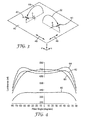
- FIG. 3 a perspective view of an optical film 40 in relation to a global x-y-z Cartesian coordinate system.
- the film 40 may be a multilayer reflective polarizer, in which case the x-, y-, and z-axes can be identical to the local x-, y-, and z- axes discussed above.
- the film 40 may be another optical film or surface, e.g., the front surface of a display system. As shown, film 40 is laid flat, parallel to the x-y plane.
- light can be considered to be polarized in two orthogonal planes, where the electric vector of the light, which is transverse to the propagation direction of the light, lies within a particular plane of polarization.
- the polarization state of a given light ray can be resolved into two orthogonal polarization states: p-polarized and s-polarized light.
- P-polarized (“p-pol”) light is light that is polarized in the plane of incidence, the plane of incidence being a plane containing both the local surface normal vector and the light ray propagation direction or vector.
- plane of incidence illustrates a light ray 42 that is incident on or emerging from optical film 40 at an oblique angle ⁇ relative to the surface normal (z-axis), thereby forming a "plane of incidence" 44.
- plane of incidence will be used herein to refer to the plane containing the surface normal direction and the light propagation direction, both in cases where the light is incident on the film, and in cases where light is not incident on the film but instead is emerging from the film.
- incidence angle may be used to refer to the angle between the surface normal direction and the light propagation direction, both for light incident on the film and for light emerging from the film.
- the film 40 is a polarizer, it includes a pass axis 46 parallel to the y-axis and a block axis 48 parallel to the x-axis.
- the plane of incidence 44 of ray 42 is parallel to the block axis 48.
- Ray 42 has a p-polarized component that is in the plane of incidence 44, and an s-polarized component that is orthogonal to the plane of incidence 44.
- FIG. 3 also shows another light ray 50 that is incident on or emerging from optical film 40 at the same oblique angle ⁇ but in a plane of incidence 52 that is parallel to the pass axis 46.
- the p-pol component of ray 50 is perpendicular to the block axis 48 and partially aligned with the pass axis 46, while the s-pol component of ray 50 is parallel to the block axis 48.
- p-polarized light can be perpendicular to the pass axis in some cases and perpendicular to the block axis in others, and s-polarized light can be parallel to the pass axis in some cases and parallel to the block axis in others.
- Any arbitrary plane of incidence can be resolved into the component incidence planes 44, 52.
- a complete discussion of the behavior of s-or p-polarized light for anisotropic systems should include not only the angle of incidence (or e.g. the angle of emergence or angle of observation) of the light, but also the plane of incidence (or e.g. the plane of emergence or plane of observation) of the light.
- the first product referred to herein as RP1 utilizes polyethylene naphthalate (“PEN”) for one of the polymers and a copolymer or blend based upon naphthalene dicarboxylic acid (“coPEN”), in particular a 55/45 copolymer blend that included hexane diol to avoid crystallization, for the other polymer.
- PEN polyethylene naphthalate
- coPEN naphthalene dicarboxylic acid
- These polymers are coextruded in an alternating layer arrangement having 275 total layers, and the extrudate is sent through a 1x3 layer multiplier that divides the extrudate and stacks the three extrudate components atop each other, the result being further processed and stretched to produce a finished reflective polarizing film with 825 total microlayers separated into three distinct microlayer packets (275 layers each) with optically thick protective boundary layers (PBLs) therebetween, and optically thick skin layers at the outer major surfaces.
- PBLs protective boundary layers
- the microlayers composed of PEN are birefringent while the microlayers composed of coPEN are substantially isotropic.
- the second product utilizes a 90/10 copolymer blend based on naphthalene dicarboxylic acid (“coPEN”) for one of the polymers and a copolyester (SA115, available from Eastman Chemical Co.) for the other polymer.
- coPEN naphthalene dicarboxylic acid
- SA115 copolyester
- These polymers are coextruded in an alternating layer arrangement with 275 total layers, and the extrudate is further processed and stretched with a parabolic tenter to produce a finished reflective polarizing film with 275 total microlayers arranged in a single microlayer packet with optically thick skin layers at the outer major surfaces.
- the microlayers composed of coPEN are birefringent while the microlayers composed of copolyester are substantially isotropic.
- Optical properties of these products are approximately as follows: RP1 RP2 n1x 1.80 1.82 n1y 1.621 1.57 n1z 1.56 1.555 n2x,n2y,n2z 1.612 1.57 ⁇ n x 0.188 0.256 ⁇ n y 0.009 (greater than 0 but less than 0.01) ⁇ n z -0.052 -0.015 N 825 275 Rpassnormal 12% 10% RpassnormalFresnel 11% 10% Rblocknormal 94% 98%
- n1x, n1y, n1z, n2x, n2y, n2z, ⁇ n x , ⁇ n y , and ⁇ n z are as described above.
- the value "N" is the total number of microlayers in the polarizer.
- Rpassnormal is the average reflectivity of the film (including both reflectivity from the front and back air/polymer interfaces and reflectivity from the microlayers) over visible wavelengths, e.g., from 400 to 700 nm, for light normally incident on the polarizer and polarized along the pass (y) axis.
- RpassnormalFresnel is the portion of Rpassnormal attributable to the Fresnel reflectivity of the front and back major surfaces exposed to air.
- Rblocknormal is the average reflectivity over visible wavelengths, e.g., from 400 to 700 nm, for light normally incident on the polarizer and polarized along the block (x) axis.
- RP2 achieves a higher block axis index difference ( ⁇ n x ) than RP1 through a combination of a higher birefringent index n1x and a lower isotropic index n2x.
- a higher ⁇ n x allows fewer layers to be used for the same block axis reflectivity, with other factors being equal, since normal incidence reflective power increases quadratically with the respective in-plane refractive index difference.
- RP1 and RP2 both have very low pass axis index differences ( ⁇ n y ), and low normal incidence pass axis reflectivities. Lower still, however, is the component of the normal incidence pass axis reflectivities attributable to the microlayers, which equals Rpassnormal - RpassnormalFresnel, or about 1% for RP1 and 0% for RP2.
- the films were placed on top of a diffusely transmissive hollow light box (a backlight).
- the diffuse transmission and reflection of the light box can be described as Lambertian.
- the hollow light box had a diffuse reflectivity of ⁇ 83%.
- the box was illuminated from within using a stabilized broadband light source.
- a standard linear absorbing polarizer i.e. an analyzer was placed between the sample box and the camera detector.
- the camera detector system was a conoscope made by Autronic-Melchers GmbH (Karlsruhe, Germany). Initially, after allowing the backlight output to stabilize, the luminance of the backlight by itself was measured over a range of observation angles in the horizontal plane. This is the plane that contains the surface normal and the p-polarized pass axis light of the output polarizer, as with plane 52 of FIG. 3 . The result is plotted as luminance curve 60 in FIG. 4 , where the horizontal axis of the graph is the polar angle in degrees from the surface normal ( ⁇ in FIG. 3 ), and the vertical axis is the measured luminance in nits (nt). As can be seen, the luminance was relatively symmetric with respect to the surface normal, and was relatively constant with angle until ⁇ reached about ⁇ 50 degrees, beyond which a drop in luminance was observed.
- the sheet of RP1 was then removed and replaced with a flat sheet of RP2, oriented in the same manner as RP1, and the measurement repeated.
- the result is plotted as luminance curve 64.
- Note again the overall luminance increase relative to the backlight alone.
- the polarizer RP2 can also be seen to exhibit a gain peak at the polar angles of about ⁇ 50 to 60 degrees by comparing curve 64 to curve 60 .
- the reflectivity for p-polarized light is close to but less than R 0 at small angles ⁇ , decreasing steadily with increasing angle ⁇ until at the Brewster angle ⁇ B the p-pol reflectivity is zero.
- the incidence angle ⁇ continues to increase beyond ⁇ B , the p-pol reflectivity increases rapidly with increasing ⁇ .
- these conditions can be replaced with a rule-of-thumb that specifies that Rpassnormal is at least 2% more than the combined normal incidence reflectivity of the major surfaces, or that the portion of Rpassnormal attributable to the microlayers is at least 2%.
- the out-of-plane index difference ⁇ n z should be negative and the in-plane index difference ⁇ n y should be positive, but less than the block axis index difference ⁇ n x .
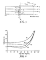
- FIG. 5 is provided to demonstrate one approach for increasing the in-plane index differences ⁇ n x , ⁇ n y .
- axes are shown for refractive indices n x , n y , and n z .
- the axes are separated vertically for clarity but otherwise have the same scale, and a refractive index scale starting at 1.0 (air) is also provided for general reference.
- Points 70, 72, 74 represent the refractive indices of microlayers composed of the first polymer material, i.e., n1x, n1y, n1z, respectively.
- the first polymer material is plainly birefringent.
- a dashed vertical line labeled n2 represents the refractive index of microlayers composed of the second polymer material.
- the intersection of that line with the n x , n y , and n z axes yield intersection points (not labeled) that represent n2x, n2y, n2z, respectively, all equal to each other.
- the second polymer material is isotropic.
- the combination of points 70, 72, 74 and the line n2 represent a multilayer reflective film comprising alternating birefringent and isotropic microlayers.
- the first and second polymer materials have been selected and the film has been processed so that the refractive index of the isotropic material matches the y-index of the birefringent material, and so that ⁇ ⁇ n x > ⁇ ⁇ n y > 0 > ⁇ ⁇ n z .
- This combination represents a reflective polarizer with no reflectivity provided by the microlayers at normal incidence for light polarized along the pass axis.
- Such a film will likely exhibit off-axis gain peaks because the pass axis reflectivity provided by the microlayers will likely not offset the Brewster angle effects of the front and back major surfaces of the polarizer exposed to air.
- the new isotropic material preferably of course has material properties that enable it to be coextruded with the polymer material that will
- this technique for increasing the index difference in the y-direction also has the effect of increasing the index differences in the other directions by the same amount.
- the original y-index difference ⁇ n y (which equals zero and thus is not shown in FIG. 5 ) increased by ⁇ n y ' to yield a new y-index difference now equal to ⁇ n y ';
- the original x-index difference ⁇ n x is increased by the same amount ⁇ n y ' to yield ⁇ n x '
- the original z-index difference ⁇ n z is increased by the same amount ⁇ n y ' to yield a smaller negative value ⁇ n z ' .
- the final y-index difference ⁇ n y ' in the new construction can in this way be associated with equal refractive index adjustments along all three axes.
- An added benefit of increasing the x-index difference by the same amount as the y-index difference is increasing the reflective power of the microlayers for the block axis, which can be used to reduce the number of layers required in the microlayer stack for a given block axis target reflectivity.
- our approach to eliminating the off-axis gain peaks by increasing the pass axis reflectivity can also help achieve a film with lower overall layer count and simpler design.
- FIG. 5 is described for a birefringent/isotropic material combination in which alternative isotropic materials are selected, this is not meant to be limiting.
- the in-plane indices can be increased by keeping the same isotropic material but substituting a different birefringent material, or keeping the same birefringent material but changing the processing conditions (stretch amount, stretch profile, temperature, dwell time, and so forth).
- constructions that use two different birefringent materials for the first and second polymer materials are also possible.
- each curve is the calculated reflectivity for particular multilayer reflective polarizer constructions for p-polarized light incident in the y-z plane (see plane 52 of FIG. 3 ) as a function of incidence angle in air (see ⁇ in FIG. 3 ).
- Each modeled polarizer construction assumed N total microlayers arranged in a single stack and exposed to air at the outer surface of the first and last microlayer. The N microlayers were arranged in an alternating arrangement of a first and second polymer, with adjacent pairs of the first and second polymer forming optical repeat units with an f-ratio of 50%.
- the optical repeat units assumed a linear optical thickness profile ranging from 200 nm for the first layer pair (corresponding to a normal incidence reflection peak at 400 nm) to 462 nm for the last layer pair (corresponding to a normal incidence reflection peak at 925 nm).
- RP6.1, RP6.2, RP6.3, and RP6.4 had the following additional properties: RP6.1 RP6.2 RP6.3 RP6.4 n1y 1.61 1.61 1.61 1.61 n1z 1.505 1.505 1.505 1.505 n2 1.61 1.595 1.564 1.564 ⁇ n y 0 0.015 0.046 0.046 ⁇ n z .105 .09 .059 .059 N 275 275 275 175
- the refractive indices in the x-direction have no effect on the modeling and are not listed.
- the birefringent refractive indices n1y, n1z that were used are representative of 90/10 coPEN oriented at ⁇ 145 °C at a stretch ratio of about 5:1 at a strain rate of about 5m/min.
- the isotropic refractive indices n2 that were used are representative of coPEN 55/45 (for RP6.1), a blend of 46% 90/10 coPEN and 54% PETG (for RP6.2), and PETG (for RP6.3 and 6.4).
- the modeling result of curve 84 was confirmed by fabricating a film having substantially the characteristics described above for the RP6.3 construction.
- a 90/10 coPEN (the birefringent material in the fmished film) and PETG (the isotropic material in the finished film) were coextruded using a 275 layer feedblock and film-making equipment similar to that described in U.S. Patent 6,783,349 (Neavin et al. ), except that no layer multiplier device was used.
- the layer thickness profile of the 275 layers was controlled to substantially match a target monotonic optical thickness profile using an axial rod heater disposed in the feedblock, whose temperature profile was dynamically adjusted along its length during coextrusion to maintain the target layer thickness profile with little deviation.
- the finished polarizing film, referred to herein as RP6.3A included an optically thick skin layer composed of PETG at both the front and back of the microlayer packet, the skin layers forming the outermost layers of the film exposed to air.
- a sheet of the RP6.3A film was placed atop the backlight referred to in connection with FIG. 4 in the same manner as films RP1 and RP2, and the resulting luminance was measured in the same way.
- the measured luminance is shown in curve 66 of FIG. 4 .
- curve 66 has no off-axis gain peaks and has a maximum gain at substantially normal incidence.
- the normal incidence gain is greater for RP6.3A than for the commercial products RP1 and RP2, despite the increased normal incidence pass axis reflectivity.
- the RP6.3A film was also inspected for on-axis and off-axis color, and it was found to be within acceptable limits due to the careful layer thickness control during fabrication.
- the polarizer film RP6.3A was fabricated without the use of a layer multiplier.
- layer multipliers can simplify the generation of a large number of optical layers, they may impart small distortions to each resultant packet of layers that are not identical for each packet. For this reason, any adjustment in the layer thickness profile of the layers generated in the feedblock is not the same for each packet, i.e., all packets produced by the multiplier cannot be simultaneously optimized to produce a uniform smooth spectrum free of spectral disruptions.
- an optimum profile and low transmission color polarizer can be difficult to make using multi-packet films manufactured using multipliers.
- the reflectivity obtained by adhering two multilayer packets together is less desirable than the reflectivity obtained by a single packet of N microlayers, as demonstrated in FIG. 7 below.
- the physical separation of the two packets in the former design results in the incoherent summation of the individual reflectivities of the packets, even though each packet individually is coherent.
- the single packet design can provide a higher block axis reflectivity for a given pass axis reflectivity, or can provide a lower pass axis reflectivity for a given block axis reflectivity, than the two packet design.
- film fabrication techniques including axial rod heater control, can be found in U.S. Patent Application No 60/939,079 (Attorney Docket No. 63274US002), filed May 20, 2007 and incorporated herein by reference.
- N the number of microlayers (N) used in the reflective polarizer design, and to the distribution of those microlayers within the film (e.g., single coherent packet, versus multiple packets separated by optically thick protective boundary layers).
- N the distribution of those microlayers within the film
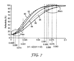
- FIG. 7 plots calculated reflectivity at normal incidence for various modeled multilayer film designs as a function of the refractive index difference between alternating microlayers.
- the model is not concerned with 2-dimensional film characteristics, and thus the refractive indices n1, n2 used in the model can represent any in-plane refractive index of the alternating layers, whether the x-axis or the y-axis refractive indices.
- the z-axis refractive indices are unimportant because they have no effect on normal-incidence behavior.
- On-axis reflectivity is plotted on the vertical axis and normalized refractive index difference (nl - n2)/(n1 + n2) is plotted on the horizontal axis.
- Each design incorporated a front and back surface of the overall construction exposed to air, producing Fresnel reflectivity.
- Each design also assumes a monotonic layer thickness gradient tailored to produce a normal incidence reflection band from 400 to 925 nm. Dispersion and absorption were neglected, and the calculated reflectivities represent averages from 400 to 700 nm, and they also represent averages from 400 to 925 nm.
- n1 and n2 were both set equal to 1.610.
- the value n1 was then increased up to 1.82 and beyond, and the reflectivity calculated for each layer design/refractive index combination.
- the curves 90, 92, 94, 96, 98 are the calculated reflectivities for the film designs SD1, SD2, SD3, SD4, SD5 respectively.
- Small refractive index differences yield small values of normalized index difference, representative of pass-axis behavior and labeled as a "Pass" region in the figure. Larger refractive index differences yield larger values of normalized index difference, representative of block-axis behavior and labeled as a "Block" region.
- each of the curves 90-96 has an individual datapoint at a normalized index difference value ((n1-n2)/(n1+n2)) of 0.022, corresponding to the index difference along the pass axis for the material combination 90/10 coPEN and coPET-f
- each of the curves 90-98 also has an individual datapoint at a normalized index difference value of 0.083, corresponding to the index difference along the block axis for the same 90/10 coPEN - coPET-f material combination.
- FIG. 7 thus shows how normal incidence reflectivity increases with changes in the in-plane index difference, for both the pass (y) and block (x) axes, and for different microlayer stack designs.
- the highest slope for the pass axis increase in reflectivity occurs for SD1, the 2-packet system with individual coherent packets of 275 layers laminated and reflecting in a non-constructive interference arrangement.
- This 2-packet construction also has the smallest increase in block axis reflectivity for a given in-plane index difference, similar to the 375 layer coherent stack design of SD2.
- the smallest slope for the pass axis increase in reflectivity occurs for SD4, and this stack design also has the highest increase in slope for the block axis, i.e., most improvement for a given in-plane index difference.
- curves 94, 96, 98 are instructive with respect to the desirability of distributing the available microlayers in a single coherent packet rather than separating them into multiple packets.
- a single packet design can provide a higher block axis reflectivity for a given pass axis reflectivity, or can provide a lower pass axis reflectivity for a given block axis reflectivity, than a two packet design.
- PETG as the low index isotropic material has the effect of increasing the in-plane index differences (both pass axis and block axis) by 0.046 relative to a construction having a perfect index match along the pass axis (using 55/45 coPEN as the low index isotropic material).
- These increased in-plane index differences produce a 10% increase in pass axis reflectivity and a 6.6% increase in block axis reflectivity for stack design SD3 (275 layers, single stack - curve 94 ) , but they produce a smaller 6.5% increase in pass axis reflectivity and a larger 11.7% increase in block axis reflectivity for stack design SD4 (175 layers, single stack - curve 96 ) .
- the smaller increase in pass axis reflectivity is beneficial for a polarizing film in maintaining a higher pass axis throughput, and the larger increase in block axis reflectivity is beneficial in keeping the loss/leakage of useable polarization low.
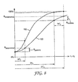
- FIG. 8 is a graph that summarizes the lessons of FIG. 7 in a similar but simplified format, and that graphically depicts the parameters Rpassnormal, Rblocknormal, Rpassinc, and Rblockinc.
- Normal incidence reflectivity is plotted against in-plane index difference n1-n2, where small values of the index difference represent the pass axis and larger values represent the block axis.
- Two curves are shown, a lower curve 100 and an upper curve 102, the features of which are intended to demonstrate general trends.
- the lower curve 100 can represent a microlayer stack design with relatively fewer microlayers N than an alternative stack design for curve 102, each of the stack designs being single packet designs that reflect over the same wavelength band.
- lower curve 100 can represent a microlayer stack design having the same number of microlayers N as that of curve 102, but the stack for curve 100 has the microlayers configured as a single coherent packet whereas the stack for curve 102 has the microlayers divided into two packets separated by an optically thick index matching material (and again each of the stack designs have a thickness gradient causing them to reflect over the same wavelength band).
- the resulting new reflectivity for the pass axis is smaller than Rpassnormal by an amount Rpassinc, and the resulting new reflectivity for the block axis is smaller than Rblocknormal by an amount Rblockinc.
- Rblockinc is comparable to Rpassinc.
- Rblockinc may be at least half of Rpassinc, or Rblockinc may be at least equal to Rpassinc.
- FIGS. 7 and 8 help to illustrate the physics of pass and block axis reflectivity increases and demonstrate that coherent multilayer stacks are advantageous, but it is also useful to calculate the expected gain for the different cases in a typical high efficiency commercial backlight. This was done and the results plotted in FIGS. 9a and 9b .
- a recycling model was used in which all reflected light was assumed to be randomized in the backlight, both in polarization and in angle of propagation. This is a good approximation for backlights that are constructed with voided polyester reflectors that are commonly used in existing commercial backlights.
- a baseline design for comparison purposes used a low index isotropic polymer material of index equal to 1.61 to drive the y-index mismatch ⁇ n y to zero.
- we include this embodiment but then we also model a range of alternative embodiments for which the isotropic index ranges from 1.61 to 1.51, and we calculate both the on-axis gain and the total (hemispheric integrated) gain for polarized light delivered to an LCD panel.
- the model assumed an absorption loss of 1% for all the films, and a backlight cavity efficiency of 90% (10% average total loss for rays entering the backlight cavity).
- the film stacks that were modeled were the stack designs SD1 (two packets of 275 layers each), SD2 (one packet of 375 layers), SD3 (one packet of 275 layers), SD4 (one packet of 175 layers), and a packet design ("SD5") having two packets of 138 microlayers each, separated by an index matching optically thick medium.
- the SD5 packet design like the others, included a layer thickness profile causing it to reflect over the wavelength band from 400 to 925 nm). Results for the SD5 design thus can be compared to results for the SD3 design to ascertain the effect of arranging substantially the same number of microlayers into a single coherent packet versus into two packets that are individually coherent but mutually incoherent.
- FIGS. 9a for modeled on-axis gain
- 9b for modeled hemispheric gain
- the horizontal axis for each graph is the pass axis refractive index difference ⁇ n y , but it is to be understood that as ⁇ n y varies from 0 to 0.1, the block axis difference varies in a corresponding fashion from 0.21 to 0.31, and the out-of-plane (z-axis) difference varies correspondingly from -0.105 to -0.005.
- the gain per layer is higher for the single packet coherent stacks compared to the 2-packet laminates of individual coherent stacks.
- the overall maximum gain is generally achieved with highest layer count, but this requires the greatest amount of PEN resin content and complexity of the feedblock needed to control the layer profiles to avoid perceived color.
- the gain is seen to reach a maximum at a certain value of ⁇ n y (or of ⁇ n) and then decrease.
- Any (or ⁇ n) is selected, via appropriate material selection and processing conditions, to maximize or substantially maximize the gain for the stack design chosen.
- ⁇ n y or ⁇ n is preferably selected sufficiently close to that particular value to achieve a gain that is at least 90% or 95% of such maximum gain.
- hemispheric or on-axis gain is maximized for ⁇ n y in a range from 0.01 to 0.06, or from 0.01 to 0.05.
- an optimum number of layers can be chosen to maximize gain with respect to cost, for example.
- the optimization procedure can also be applied to films having birefringent indices lower than those for PEN, e.g., to pure PET based birefringent materials. PET is generally lower cost than PEN, but requires more layers due to the smaller index differences typically achievable and thus also slower line speeds.
- N is preferably 800 or less, or 650 or less, or in a range from 300 to 650, or in a range from 500 to 650.
- Reflectivities of the foregoing films are generally reflectivity averages over the visible spectrum, 400 - 700 nm, but other ranges can also be used.
- Rpassnormal, Rblocknormal, Rpassinc, and Rblockinc may thus represent reflectivity averages, but they may also represent reflectivity averages that extend into the infrared region (e.g. 400 - 925 nm) to ensure adequate off-axis performance.
- R oblique 1 - T oblique - A.
- the value of A may be slightly different at oblique angles and corrections may be made if desired. Near 55 degrees however the corrections are minor.
- Measurements of T oblique are difficult to measure with an integrating sphere if there is substantial diffusion in the film.
- diffusers can increase the absorption of a film.
- a diffuse layer may be smoothed over by a coating or by a laminate if it is a surface diffuser, or it may be stripped away e.g. by polishing or by laser ablation if it is a bulk diffuser incorporated in an outer layer of the film such as a skin layer or a protective boundary layer.
Landscapes
- Physics & Mathematics (AREA)
- General Physics & Mathematics (AREA)
- Optics & Photonics (AREA)
- Polarising Elements (AREA)
- Liquid Crystal (AREA)
Applications Claiming Priority (2)
| Application Number | Priority Date | Filing Date | Title |
|---|---|---|---|
| US4091008P | 2008-03-31 | 2008-03-31 | |
| EP09729145.4A EP2263111B1 (fr) | 2008-03-31 | 2009-03-27 | Polariseur réfléchissant à nombre réduit de couches et à gain optimisé |
Related Parent Applications (2)
| Application Number | Title | Priority Date | Filing Date |
|---|---|---|---|
| EP09729145.4A Division-Into EP2263111B1 (fr) | 2008-03-31 | 2009-03-27 | Polariseur réfléchissant à nombre réduit de couches et à gain optimisé |
| EP09729145.4 Division | 2009-03-27 |
Publications (1)
| Publication Number | Publication Date |
|---|---|
| EP2602647A1 true EP2602647A1 (fr) | 2013-06-12 |
Family
ID=40638085
Family Applications (2)
| Application Number | Title | Priority Date | Filing Date |
|---|---|---|---|
| EP13158137.3A Withdrawn EP2602647A1 (fr) | 2008-03-31 | 2009-03-27 | Polariseur réfléchissant à nombre réduit de couches et à gain optimisé |
| EP09729145.4A Active EP2263111B1 (fr) | 2008-03-31 | 2009-03-27 | Polariseur réfléchissant à nombre réduit de couches et à gain optimisé |
Family Applications After (1)
| Application Number | Title | Priority Date | Filing Date |
|---|---|---|---|
| EP09729145.4A Active EP2263111B1 (fr) | 2008-03-31 | 2009-03-27 | Polariseur réfléchissant à nombre réduit de couches et à gain optimisé |
Country Status (8)
| Country | Link |
|---|---|
| US (2) | US9110245B2 (fr) |
| EP (2) | EP2602647A1 (fr) |
| JP (3) | JP2011516920A (fr) |
| KR (1) | KR101633133B1 (fr) |
| CN (1) | CN102016659B (fr) |
| MY (1) | MY163688A (fr) |
| TW (1) | TWI570451B (fr) |
| WO (1) | WO2009123928A1 (fr) |
Families Citing this family (43)
| Publication number | Priority date | Publication date | Assignee | Title |
|---|---|---|---|---|
| WO2009123928A1 (fr) | 2008-03-31 | 2009-10-08 | 3M Innovative Properties Company | Polariseur réfléchissant à nombre réduit de couches et à gain optimisé |
| KR101691671B1 (ko) * | 2008-03-31 | 2016-12-30 | 쓰리엠 이노베이티브 프로퍼티즈 컴파니 | 광학 필름 |
| EP2366122B1 (fr) * | 2008-11-19 | 2018-09-26 | 3M Innovative Properties Company | Film optique multicouche avec confinement de la sortie dans les directions polaire et azimutale, et constructions associées |
| US20110222263A1 (en) * | 2008-11-19 | 2011-09-15 | Weber Michael F | High transmission flux leveling multilayer optical film and related constructions |
| CN102282014B (zh) | 2008-11-19 | 2015-01-21 | 3M创新有限公司 | 在极角和方位角方向均具有输出限制的反射膜组合及相关构造 |
| EP2366077B1 (fr) | 2008-11-19 | 2018-08-15 | 3M Innovative Properties Company | Film à angle de brewster pour la prise en charge de la lumière dans des luminaires et d'autres systèmes d'éclairage |
| WO2011050268A1 (fr) * | 2009-10-24 | 2011-04-28 | 3M Innovative Properties Company | Polariseur réfléchissant immergé possédant une réflectivité décalée élevée |
| EP2491442A1 (fr) | 2009-10-24 | 2012-08-29 | 3M Innovative Properties Company | Polariseur réfléchissant immergé présentant un confinement angulaire dans des plans d'incidence sélectionnés |
| EP2491445B1 (fr) | 2009-10-24 | 2018-01-03 | 3M Innovative Properties Company | Source de lumière et système d'affichage l'intégrant |
| EP3258167A3 (fr) | 2009-12-08 | 2018-04-18 | 3M Innovative Properties Co. | Constructions optique comprenant un guide de lumière et des films à faible indice de réfraction |
| MY166721A (en) * | 2010-05-21 | 2018-07-18 | 3M Innovative Properties Co | Partially reflecting multilayer optical films with reduced color |
| KR101994490B1 (ko) | 2010-12-10 | 2019-06-28 | 쓰리엠 이노베이티브 프로퍼티즈 컴파니 | 눈부심 감소 창유리 물품 |
| CN102628968B (zh) * | 2012-01-04 | 2013-08-07 | 京东方科技集团股份有限公司 | 一种聚光膜、背光模组和液晶显示面板 |
| TWI474079B (zh) * | 2012-03-14 | 2015-02-21 | Extend Optronics Corp | 反射式光學膜及其製作方法、及影像顯示器 |
| JP6062923B2 (ja) * | 2012-03-30 | 2017-01-18 | 株式会社きもと | エッジライト型バックライト装置及び光拡散性部材 |
| US9279921B2 (en) * | 2013-04-19 | 2016-03-08 | 3M Innovative Properties Company | Multilayer stack with overlapping harmonics for wide visible-infrared coverage |
| KR102371165B1 (ko) | 2013-09-06 | 2022-03-07 | 쓰리엠 이노베이티브 프로퍼티즈 컴파니 | 다층 광학 필름 |
| CN105492940B (zh) | 2013-09-06 | 2019-09-03 | 3M创新有限公司 | 多层反射偏振片 |
| JP6576913B2 (ja) * | 2013-09-30 | 2019-09-18 | スリーエム イノベイティブ プロパティズ カンパニー | 多層光学フィルム |
| US9919339B2 (en) | 2014-06-18 | 2018-03-20 | 3M Innovation Properties Company | Optical film |
| US9823395B2 (en) * | 2014-10-17 | 2017-11-21 | 3M Innovative Properties Company | Multilayer optical film having overlapping harmonics |
| WO2016205130A1 (fr) | 2015-06-15 | 2016-12-22 | 3M Innovative Properties Company | Empilement optique comprenant un polariseur réfléchissant-absorbant |
| US11125921B2 (en) | 2015-07-24 | 2021-09-21 | 3M Innovative Properties Company | Reflective stack with heat spreading layer |
| WO2017039721A1 (fr) | 2015-09-03 | 2017-03-09 | 3M Innovative Properties Company | Polariseur réfléchissant multicouche thermoformé |
| JP7010450B2 (ja) | 2015-11-16 | 2022-01-26 | スリーエム イノベイティブ プロパティズ カンパニー | 単一パケット2軸複屈折反射型偏光子を有するディスプレイ積層体 |
| CN111856634B (zh) * | 2015-12-18 | 2022-08-09 | 3M创新有限公司 | 宽带可见光反射器 |
| JP6687811B2 (ja) * | 2016-09-13 | 2020-04-28 | スリーエム イノベイティブ プロパティズ カンパニー | 斜角における色抑制のために調整された厚さプロファイルを有する単一パケット反射型偏光子 |
| US11536886B2 (en) | 2017-06-26 | 2022-12-27 | 3M Innovative Properties Company | Roll of film including multilayer birefringent reflective polarizer having low pass axis variation |
| WO2019003107A1 (fr) | 2017-06-26 | 2019-01-03 | 3M Innovative Properties Company | Rouleau de film comprenant un polariseur réfléchissant biréfringent multicouche et une couche d'alcool polyvinylique et présentant une faible variation d'axe de passage |
| CN111164471B (zh) * | 2017-10-02 | 2022-05-17 | 3M创新有限公司 | 用于校正色移的部分反射器 |
| CN111344613B (zh) * | 2017-10-09 | 2022-09-27 | 3M创新有限公司 | 光学部件和光学系统 |
| WO2019077547A1 (fr) * | 2017-10-20 | 2019-04-25 | 3M Innovative Properties Company | Film optique et séparateur de faisceau de polarisation |
| US11073646B2 (en) | 2017-12-01 | 2021-07-27 | 3M Innovative Properties Company | Thin multilayer reflector with uniform left bandedge |
| CN111492278B (zh) * | 2017-12-20 | 2022-04-26 | 3M创新有限公司 | 光学叠堆和偏振分束器 |
| CN112041735B (zh) | 2018-05-02 | 2023-09-01 | 3M创新有限公司 | 多层反射器 |
| EP3802083A1 (fr) * | 2018-06-04 | 2021-04-14 | 3M Innovative Properties Company | Film optique multicouche résistant à l'abrasion thermoformé et son procédé de fabrication |
| US11226482B2 (en) | 2018-06-07 | 2022-01-18 | Facebook Technologies, Llc | Reverse-order crossed pancake lens with azimuthal compensation |
| US11927783B2 (en) | 2018-07-13 | 2024-03-12 | 3M Innovative Properties Company | Optical system and optical film |
| US11971560B2 (en) | 2018-07-20 | 2024-04-30 | 3M Innovative Properties Company | Optical film including polymeric optical reflector and discontinuous transparent coating |
| US20210325587A1 (en) * | 2018-09-06 | 2021-10-21 | 3M Innovative Properties Company | Multilayer reflective polarizer with crystalline low index layers |
| JP7462633B2 (ja) * | 2018-12-07 | 2024-04-05 | スリーエム イノベイティブ プロパティズ カンパニー | 光学フィルム及び偏光ビームスプリッタ |
| TW202102882A (zh) | 2019-03-11 | 2021-01-16 | 美商3M新設資產公司 | 具有減少色彩之高效率紅外線反射器 |
| US11662510B2 (en) | 2020-01-07 | 2023-05-30 | Meta Platforms Technologies, Llc | Optically anisotropic polymer thin films |
Citations (14)
| Publication number | Priority date | Publication date | Assignee | Title |
|---|---|---|---|---|
| US3610729A (en) | 1969-06-18 | 1971-10-05 | Polaroid Corp | Multilayered light polarizer |
| US4446305A (en) | 1981-03-02 | 1984-05-01 | Polaroid Corporation | Optical device including birefringent polymer |
| US4540623A (en) | 1983-10-14 | 1985-09-10 | The Dow Chemical Company | Coextruded multi-layered articles |
| US5103337A (en) | 1990-07-24 | 1992-04-07 | The Dow Chemical Company | Infrared reflective optical interference film |
| US5360659A (en) | 1993-05-24 | 1994-11-01 | The Dow Chemical Company | Two component infrared reflecting film |
| WO1995017303A1 (fr) | 1993-12-21 | 1995-06-29 | Minnesota Mining And Manufacturing Company | Film optique multicouche |
| US5448404A (en) | 1992-10-29 | 1995-09-05 | The Dow Chemical Company | Formable reflective multilayer body |
| US5882774A (en) | 1993-12-21 | 1999-03-16 | Minnesota Mining And Manufacturing Company | Optical film |
| WO1999039224A1 (fr) | 1998-01-28 | 1999-08-05 | Minnesota Mining And Manufacturing Company | Filtre interferentiel infrarouge |
| US6157490A (en) | 1998-01-13 | 2000-12-05 | 3M Innovative Properties Company | Optical film with sharpened bandedge |
| US6368699B1 (en) | 1995-06-26 | 2002-04-09 | 3M Innovative Properties Company | Multilayer polymer film with additional coatings or layers |
| US6531230B1 (en) | 1998-01-13 | 2003-03-11 | 3M Innovative Properties Company | Color shifting film |
| US6783349B2 (en) | 1998-01-13 | 2004-08-31 | 3M Innovative Properties Company | Apparatus for making multilayer optical films |
| US20060232863A1 (en) * | 2005-04-18 | 2006-10-19 | 3M Innovative Properties Company | Thick film multilayer reflector with tailored layer thickness profile |
Family Cites Families (89)
| Publication number | Priority date | Publication date | Assignee | Title |
|---|---|---|---|---|
| CA1024293A (fr) * | 1972-08-28 | 1978-01-10 | E.I. Du Pont De Nemours And Company | Film polymerique, structures laminees a film polymerique et articles fabriques a partir de ces structures |
| GB1497101A (en) * | 1975-08-04 | 1978-01-05 | Ici Ltd | Coated film assemblies |
| JPS5695902A (en) * | 1979-12-29 | 1981-08-03 | Toyobo Co Ltd | Uv-curable resin composition |
| DE69333329T2 (de) * | 1992-01-07 | 2004-09-09 | Mitsubishi Polyester Film Corp. | Polyesterfilm |
| US5427835A (en) * | 1992-06-04 | 1995-06-27 | Minnesota Mining And Manufacturing Company | Sulfopolymer/vanadium oxide antistatic compositions |
| TW289095B (fr) * | 1993-01-11 | 1996-10-21 | ||
| US5474730A (en) * | 1993-06-09 | 1995-12-12 | Hoechst Celanese Corporation | Production of highly birefringent film |
| US5570214A (en) * | 1993-12-15 | 1996-10-29 | Ois Optical Imaging Systems, Inc. | Normally white twisted nematic LCD with retardation films on opposite sides of liquid crystal material for improved viewing zone |
| KR100432457B1 (ko) | 1993-12-21 | 2004-05-22 | 미네소타 마이닝 앤드 매뉴팩춰링 캄파니 | 휘도 향상 디바이스 |
| WO1995017691A1 (fr) | 1993-12-21 | 1995-06-29 | Minnesota Mining And Manufacturing Company | Polariseur optique |
| US5828488A (en) * | 1993-12-21 | 1998-10-27 | Minnesota Mining And Manufacturing Co. | Reflective polarizer display |
| AU1443595A (en) | 1993-12-21 | 1995-07-10 | Minnesota Mining And Manufacturing Company | Reflective polarizer with brightness enhancement |
| US6101032A (en) * | 1994-04-06 | 2000-08-08 | 3M Innovative Properties Company | Light fixture having a multilayer polymeric film |
| US5751388A (en) * | 1995-04-07 | 1998-05-12 | Honeywell Inc. | High efficiency polarized display |
| WO1997001781A2 (fr) * | 1995-06-26 | 1997-01-16 | Minnesota Mining And Manufacturing Company | Polariseurs et miroirs multicouches a reflexion diffuse |
| US6080467A (en) * | 1995-06-26 | 2000-06-27 | 3M Innovative Properties Company | High efficiency optical devices |
| US5867316A (en) * | 1996-02-29 | 1999-02-02 | Minnesota Mining And Manufacturing Company | Multilayer film having a continuous and disperse phase |
| US5825543A (en) * | 1996-02-29 | 1998-10-20 | Minnesota Mining And Manufacturing Company | Diffusely reflecting polarizing element including a first birefringent phase and a second phase |
| US6497946B1 (en) * | 1997-10-24 | 2002-12-24 | 3M Innovative Properties Company | Diffuse reflective articles |
| JPH11142646A (ja) * | 1997-11-07 | 1999-05-28 | Seiko Epson Corp | 反射偏光子、液晶装置及び電子機器 |
| US6593423B1 (en) * | 2000-05-03 | 2003-07-15 | Ppg Industries Ohio, Inc. | Adhesion promoting agent and coating compositions for polymeric substrates |
| US6179948B1 (en) * | 1998-01-13 | 2001-01-30 | 3M Innovative Properties Company | Optical film and process for manufacture thereof |
| US6788463B2 (en) * | 1998-01-13 | 2004-09-07 | 3M Innovative Properties Company | Post-formable multilayer optical films and methods of forming |
| KR100601228B1 (ko) | 1998-01-13 | 2006-07-19 | 미네소타 마이닝 앤드 매뉴팩춰링 캄파니 | 다층 광학 필름의 제조 방법 |
| CN1104325C (zh) | 1998-01-13 | 2003-04-02 | 美国3M公司 | 改性共聚聚酯和改进的多层反射薄膜 |
| DE19808226C1 (de) * | 1998-02-27 | 2000-03-02 | Bruker Analytik Gmbh | Anordnung und Verfahren zur Untersuchung von hydrophilen Makromolekülen in wässriger Lösung |
| TW522273B (en) | 1998-08-07 | 2003-03-01 | Matsushita Electric Ind Co Ltd | Reflection type liquid crystal display element |
| US6235850B1 (en) * | 1998-12-11 | 2001-05-22 | 3M Immovative Properties Company | Epoxy/acrylic terpolymer self-fixturing adhesive |
| US6972813B1 (en) * | 1999-06-09 | 2005-12-06 | 3M Innovative Properties Company | Optical laminated bodies, lighting equipment and area luminescence equipment |
| US6122103A (en) | 1999-06-22 | 2000-09-19 | Moxtech | Broadband wire grid polarizer for the visible spectrum |
| JP2001042125A (ja) * | 1999-08-04 | 2001-02-16 | Nitto Denko Corp | 偏光部材、光学部材及び液晶表示装置 |
| JP2003514977A (ja) * | 1999-11-22 | 2003-04-22 | スリーエム イノベイティブ プロパティズ カンパニー | 水をベースとするコーティング組成物 |
| EP1120828B1 (fr) * | 2000-01-28 | 2005-04-06 | STMicroelectronics S.r.l. | Procédé et circuit pour effectuer une opération d'ajustage dans circuits électroniques |
| US6590707B1 (en) * | 2000-03-31 | 2003-07-08 | 3M Innovative Properties Company | Birefringent reflectors using isotropic materials and form birefringence |
| US20010038140A1 (en) * | 2000-04-06 | 2001-11-08 | Karker Jeffrey A. | High rigidity, multi-layered semiconductor package and method of making the same |
| CN1249464C (zh) * | 2001-01-15 | 2006-04-05 | 3M创新有限公司 | 在可见光波长区域具有高且平滑透射率的多层红外反射薄膜及由该薄膜制造的层压制品 |
| US6917399B2 (en) * | 2001-02-22 | 2005-07-12 | 3M Innovative Properties Company | Optical bodies containing cholesteric liquid crystal material and methods of manufacture |
| KR100757785B1 (ko) * | 2001-07-12 | 2007-09-11 | 삼성전자주식회사 | 액정표시장치에서의 광 조명 방법 및 이를 이용한액정표시장치 |
| EP1448679B1 (fr) * | 2001-11-02 | 2007-04-11 | SKC Limited | Film polyester thermoretractable |
| US6937303B2 (en) * | 2001-12-18 | 2005-08-30 | Samsung Electronics Co., Ltd. | Transmissive and reflective type liquid crystal display |
| US6991695B2 (en) * | 2002-05-21 | 2006-01-31 | 3M Innovative Properties Company | Method for subdividing multilayer optical film cleanly and rapidly |
| FR2841659A1 (fr) | 2002-06-28 | 2004-01-02 | Thomson Licensing Sa | Dispositif d'illumination a lumiere polarisee |
| JP2004077318A (ja) * | 2002-08-20 | 2004-03-11 | Uchiyama Mfg Corp | 磁気エンコーダ |
| US6949212B2 (en) * | 2002-11-27 | 2005-09-27 | 3M Innovative Properties Company | Methods and devices for stretching polymer films |
| US7094461B2 (en) * | 2002-12-31 | 2006-08-22 | 3M Innovative Properties Company | P-polarizer with large z-axis refractive index difference |
| JP4432513B2 (ja) * | 2003-03-31 | 2010-03-17 | 東ソー株式会社 | 光学フィルム用樹脂組成物及び光学フィルム |
| US7041365B2 (en) * | 2003-05-12 | 2006-05-09 | 3M Innovative Properties Company | Static dissipative optical construction |
| US7252733B2 (en) * | 2004-05-04 | 2007-08-07 | Eastman Kodak Company | Polarizer guarded cover sheet with adhesion promoter |
| US20060027321A1 (en) * | 2004-08-09 | 2006-02-09 | 3M Innovative Properties Company | Adhesive composition |
| US20060029784A1 (en) * | 2004-08-09 | 2006-02-09 | 3M Innovative Properties Company | Laminated optical article |
| KR100733150B1 (ko) * | 2004-10-04 | 2007-06-27 | 롬 앤드 하아스 컴패니 | 반응성 핫-멜트 접착제 |
| US7345137B2 (en) * | 2004-10-18 | 2008-03-18 | 3M Innovative Properties Company | Modified copolyesters and optical films including modified copolyesters |
| US20080102262A1 (en) * | 2004-11-08 | 2008-05-01 | Mitsubishi Chemical Corporation | Radiation Curable Composition and Curing Product Thereof, and Laminate Including the Same |
| US20060099411A1 (en) * | 2004-11-10 | 2006-05-11 | Jianhui Xia | Multi-layer pressure sensitive adhesive for optical assembly |
| US20060103777A1 (en) * | 2004-11-15 | 2006-05-18 | 3M Innovative Properties Company | Optical film having a structured surface with rectangular based prisms |
| US7220026B2 (en) * | 2004-12-30 | 2007-05-22 | 3M Innovative Properties Company | Optical film having a structured surface with offset prismatic structures |
| US7320538B2 (en) * | 2004-12-30 | 2008-01-22 | 3M Innovative Properties Company | Optical film having a structured surface with concave pyramid-shaped structures |
| US7416309B2 (en) * | 2004-12-30 | 2008-08-26 | 3M Innovative Properties Company | Optical film having a surface with rounded structures |
| JP4515357B2 (ja) * | 2005-01-27 | 2010-07-28 | リンテック株式会社 | 偏光板用粘着剤、粘着剤付き偏光板及びその製造方法 |
| US20060216524A1 (en) * | 2005-03-23 | 2006-09-28 | 3M Innovative Properties Company | Perfluoropolyether urethane additives having (meth)acryl groups and hard coats |
| US20060221447A1 (en) * | 2005-03-31 | 2006-10-05 | 3M Innovative Properties Company | Stabilized polarizing beam splitter assembly |
| US20060226561A1 (en) * | 2005-04-08 | 2006-10-12 | 3M Innovative Properties Company | Heat setting optical films |
| KR20080010419A (ko) * | 2005-04-18 | 2008-01-30 | 쓰리엠 이노베이티브 프로퍼티즈 컴파니 | 디스플레이용 다기능성 후막 반사 편광기 |
| US20060250707A1 (en) * | 2005-05-05 | 2006-11-09 | 3M Innovative Properties Company | Optical film having a surface with rounded pyramidal structures |
| US20080198293A1 (en) | 2005-05-27 | 2008-08-21 | Koninklijke Philips Electronics, N.V. | Illumination Device For a Display, and Method of Manufacturing the Same |
| US7557989B2 (en) * | 2005-06-03 | 2009-07-07 | 3M Innovative Properties Company | Reflective polarizer and display device having the same |
| US20060291055A1 (en) * | 2005-06-15 | 2006-12-28 | 3M Innovative Properties Company | Diffuse Multilayer Optical Article |
| JP2005321830A (ja) * | 2005-06-28 | 2005-11-17 | Seiko Epson Corp | 液晶装置及び電子機器 |
| US20070024994A1 (en) * | 2005-07-29 | 2007-02-01 | 3M Innovative Properties Company | Structured optical film with interspersed pyramidal structures |
| JP2007065160A (ja) * | 2005-08-30 | 2007-03-15 | Keiwa Inc | 光学シート用基材フィルム、光学シート及びバックライトユニット |
| US20070047080A1 (en) * | 2005-08-31 | 2007-03-01 | 3M Innovative Properties Company | Methods of producing multilayer reflective polarizer |
| JP2007131698A (ja) | 2005-10-11 | 2007-05-31 | Mitsubishi Chemicals Corp | 放射線硬化性組成物及びその硬化物、並びにその積層体 |
| US20070131698A1 (en) * | 2005-12-13 | 2007-06-14 | Antal Keith E Sr | Thermal food tray |
| KR100952104B1 (ko) * | 2006-01-27 | 2010-04-13 | 주식회사 코오롱 | 열수축성 폴리에스테르계 필름 |
| US8092904B2 (en) * | 2006-03-31 | 2012-01-10 | 3M Innovative Properties Company | Optical article having an antistatic layer |
| US20080002256A1 (en) * | 2006-06-30 | 2008-01-03 | 3M Innovative Properties Company | Optical article including a beaded layer |
| US7905650B2 (en) * | 2006-08-25 | 2011-03-15 | 3M Innovative Properties Company | Backlight suitable for display devices |
| US8007118B2 (en) * | 2006-08-31 | 2011-08-30 | 3M Innovative Properties Company | Direct-lit backlight with angle-dependent birefringent diffuser |
| KR101464795B1 (ko) * | 2007-05-20 | 2014-11-27 | 쓰리엠 이노베이티브 프로퍼티즈 컴파니 | 광 재순환 중공 공동형 디스플레이 백라이트 |
| US8449970B2 (en) * | 2007-07-23 | 2013-05-28 | 3M Innovative Properties Company | Antistatic article, method of making the same, and display device having the same |
| KR20100103561A (ko) * | 2007-12-12 | 2010-09-27 | 쓰리엠 이노베이티브 프로퍼티즈 컴파니 | 광학 필름 적층체 |
| JP5519630B2 (ja) * | 2008-03-26 | 2014-06-11 | スリーエム イノベイティブ プロパティズ カンパニー | 2種以上の流体をスライド塗布する方法 |
| EP2268417A1 (fr) * | 2008-03-26 | 2011-01-05 | 3M Innovative Properties Company | Procédés de revêtement par glissement de deux ou plusieurs fluides |
| WO2009120646A1 (fr) * | 2008-03-26 | 2009-10-01 | 3M Innovative Properties Company | Procédés d’application de fluides de glissement qui contiennent des précurseurs polymères à unités multiples |
| CN102027049B (zh) * | 2008-03-28 | 2013-11-06 | 3M创新有限公司 | 用于光学制品的厚聚酯膜以及光学制品 |
| US20110043727A1 (en) * | 2008-03-31 | 2011-02-24 | 3M Innovative Properties Company | Adhesive layer for multilayer optical film |
| KR101691671B1 (ko) * | 2008-03-31 | 2016-12-30 | 쓰리엠 이노베이티브 프로퍼티즈 컴파니 | 광학 필름 |
| WO2009123921A1 (fr) | 2008-03-31 | 2009-10-08 | 3M Innovative Properties Company | Couche primaire pour film optique multicouche |
| WO2009123928A1 (fr) | 2008-03-31 | 2009-10-08 | 3M Innovative Properties Company | Polariseur réfléchissant à nombre réduit de couches et à gain optimisé |
-
2009
- 2009-03-27 WO PCT/US2009/038585 patent/WO2009123928A1/fr active Application Filing
- 2009-03-27 KR KR1020107023918A patent/KR101633133B1/ko active IP Right Grant
- 2009-03-27 EP EP13158137.3A patent/EP2602647A1/fr not_active Withdrawn
- 2009-03-27 US US12/935,500 patent/US9110245B2/en active Active
- 2009-03-27 CN CN200980114666.7A patent/CN102016659B/zh not_active Expired - Fee Related
- 2009-03-27 EP EP09729145.4A patent/EP2263111B1/fr active Active
- 2009-03-27 MY MYPI2010004532A patent/MY163688A/en unknown
- 2009-03-27 JP JP2011503057A patent/JP2011516920A/ja not_active Withdrawn
- 2009-03-30 TW TW098110518A patent/TWI570451B/zh not_active IP Right Cessation
-
2014
- 2014-08-01 JP JP2014157572A patent/JP6073837B2/ja active Active
-
2015
- 2015-07-16 US US14/800,982 patent/US9513420B2/en active Active
-
2016
- 2016-09-09 JP JP2016176304A patent/JP6521922B2/ja active Active
Patent Citations (14)
| Publication number | Priority date | Publication date | Assignee | Title |
|---|---|---|---|---|
| US3610729A (en) | 1969-06-18 | 1971-10-05 | Polaroid Corp | Multilayered light polarizer |
| US4446305A (en) | 1981-03-02 | 1984-05-01 | Polaroid Corporation | Optical device including birefringent polymer |
| US4540623A (en) | 1983-10-14 | 1985-09-10 | The Dow Chemical Company | Coextruded multi-layered articles |
| US5103337A (en) | 1990-07-24 | 1992-04-07 | The Dow Chemical Company | Infrared reflective optical interference film |
| US5448404A (en) | 1992-10-29 | 1995-09-05 | The Dow Chemical Company | Formable reflective multilayer body |
| US5360659A (en) | 1993-05-24 | 1994-11-01 | The Dow Chemical Company | Two component infrared reflecting film |
| WO1995017303A1 (fr) | 1993-12-21 | 1995-06-29 | Minnesota Mining And Manufacturing Company | Film optique multicouche |
| US5882774A (en) | 1993-12-21 | 1999-03-16 | Minnesota Mining And Manufacturing Company | Optical film |
| US6368699B1 (en) | 1995-06-26 | 2002-04-09 | 3M Innovative Properties Company | Multilayer polymer film with additional coatings or layers |
| US6157490A (en) | 1998-01-13 | 2000-12-05 | 3M Innovative Properties Company | Optical film with sharpened bandedge |
| US6531230B1 (en) | 1998-01-13 | 2003-03-11 | 3M Innovative Properties Company | Color shifting film |
| US6783349B2 (en) | 1998-01-13 | 2004-08-31 | 3M Innovative Properties Company | Apparatus for making multilayer optical films |
| WO1999039224A1 (fr) | 1998-01-28 | 1999-08-05 | Minnesota Mining And Manufacturing Company | Filtre interferentiel infrarouge |
| US20060232863A1 (en) * | 2005-04-18 | 2006-10-19 | 3M Innovative Properties Company | Thick film multilayer reflector with tailored layer thickness profile |
Non-Patent Citations (3)
| Title |
|---|
| A. THELAN: "Design of Optical Interference Filters", 1989, MCGRAW-HILL, INC. |
| H. A. MACLEOD: "Thin-Film Optical Filters, 2nd Ed.,", 1986, MACMILLAN PUBLISHING CO. |
| WEBER: "Giant Birefringent Optics in Multilayer Polymer Mirrors", SCIENCE, vol. 287, March 2000 (2000-03-01), XP000990141, DOI: doi:10.1126/science.287.5462.2451 |
Also Published As
| Publication number | Publication date |
|---|---|
| US9513420B2 (en) | 2016-12-06 |
| JP6521922B2 (ja) | 2019-05-29 |
| JP2017004010A (ja) | 2017-01-05 |
| TWI570451B (zh) | 2017-02-11 |
| WO2009123928A1 (fr) | 2009-10-08 |
| TW200946996A (en) | 2009-11-16 |
| JP6073837B2 (ja) | 2017-02-01 |
| CN102016659B (zh) | 2014-04-23 |
| CN102016659A (zh) | 2011-04-13 |
| JP2014219696A (ja) | 2014-11-20 |
| KR20110002047A (ko) | 2011-01-06 |
| MY163688A (en) | 2017-10-13 |
| JP2011516920A (ja) | 2011-05-26 |
| US9110245B2 (en) | 2015-08-18 |
| EP2263111A1 (fr) | 2010-12-22 |
| US20110102891A1 (en) | 2011-05-05 |
| EP2263111B1 (fr) | 2019-05-29 |
| KR101633133B1 (ko) | 2016-06-23 |
| US20150316697A1 (en) | 2015-11-05 |
Similar Documents
| Publication | Publication Date | Title |
|---|---|---|
| US9513420B2 (en) | Low layer count reflective polarizer with optimized gain | |
| CN110383123B (zh) | 高对比度光学膜和包括该光学膜的设备 | |
| US11280947B2 (en) | Multilayer reflective polarizer | |
| JP3448626B2 (ja) | 反射偏光子ディスプレイ | |
| US6025897A (en) | Display with reflective polarizer and randomizing cavity | |
| US6101032A (en) | Light fixture having a multilayer polymeric film | |
| US9158155B2 (en) | Immersed reflective polarizer with high off-axis reflectivity | |
| US20090079909A1 (en) | Display incorporating reflective polarizer | |
| TW201527806A (zh) | 聚合多層光學膜 | |
| JP2020501184A (ja) | 光学積層体 | |
| US20180372932A1 (en) | Broadband visible reflector | |
| KR20190009426A (ko) | 반사 편광기 및 보상 필름을 포함하는 광학 적층물 | |
| CN113640911B (zh) | 显示器组件、光学叠堆、光学系统及偏振分束器 |
Legal Events
| Date | Code | Title | Description |
|---|---|---|---|
| PUAI | Public reference made under article 153(3) epc to a published international application that has entered the european phase |
Free format text: ORIGINAL CODE: 0009012 |
|
| AC | Divisional application: reference to earlier application |
Ref document number: 2263111 Country of ref document: EP Kind code of ref document: P |
|
| AK | Designated contracting states |
Kind code of ref document: A1 Designated state(s): AT BE BG CH CY CZ DE DK EE ES FI FR GB GR HR HU IE IS IT LI LT LU LV MC MK MT NL NO PL PT RO SE SI SK TR |
|
| 17P | Request for examination filed |
Effective date: 20131212 |
|
| RBV | Designated contracting states (corrected) |
Designated state(s): AT BE BG CH CY CZ DE DK EE ES FI FR GB GR HR HU IE IS IT LI LT LU LV MC MK MT NL NO PL PT RO SE SI SK TR |
|
| 17Q | First examination report despatched |
Effective date: 20140527 |
|
| STAA | Information on the status of an ep patent application or granted ep patent |
Free format text: STATUS: EXAMINATION IS IN PROGRESS |
|
| STAA | Information on the status of an ep patent application or granted ep patent |
Free format text: STATUS: EXAMINATION IS IN PROGRESS |
|
| STAA | Information on the status of an ep patent application or granted ep patent |
Free format text: STATUS: THE APPLICATION IS DEEMED TO BE WITHDRAWN |
|
| 18D | Application deemed to be withdrawn |
Effective date: 20201001 |