EP2600366A1 - Beweglicher Kontakt und Kontaktstruktur damit - Google Patents
Beweglicher Kontakt und Kontaktstruktur damit Download PDFInfo
- Publication number
- EP2600366A1 EP2600366A1 EP20120250169 EP12250169A EP2600366A1 EP 2600366 A1 EP2600366 A1 EP 2600366A1 EP 20120250169 EP20120250169 EP 20120250169 EP 12250169 A EP12250169 A EP 12250169A EP 2600366 A1 EP2600366 A1 EP 2600366A1
- Authority
- EP
- European Patent Office
- Prior art keywords
- contact
- contacts
- movable contact
- sliders
- fixed
- Prior art date
- Legal status (The legal status is an assumption and is not a legal conclusion. Google has not performed a legal analysis and makes no representation as to the accuracy of the status listed.)
- Withdrawn
Links
- WABPQHHGFIMREM-UHFFFAOYSA-N lead(0) Chemical compound [Pb] WABPQHHGFIMREM-UHFFFAOYSA-N 0.000 claims description 16
- 238000005299 abrasion Methods 0.000 abstract description 4
- 239000004020 conductor Substances 0.000 description 5
- 230000000881 depressing effect Effects 0.000 description 5
- 239000000470 constituent Substances 0.000 description 4
- 230000002093 peripheral effect Effects 0.000 description 2
- 230000000052 comparative effect Effects 0.000 description 1
- 239000012212 insulator Substances 0.000 description 1
- 238000004519 manufacturing process Methods 0.000 description 1
- 239000000463 material Substances 0.000 description 1
- 230000004048 modification Effects 0.000 description 1
- 238000012986 modification Methods 0.000 description 1
- 230000003287 optical effect Effects 0.000 description 1
Images


Classifications
-
- H—ELECTRICITY
- H01—ELECTRIC ELEMENTS
- H01H—ELECTRIC SWITCHES; RELAYS; SELECTORS; EMERGENCY PROTECTIVE DEVICES
- H01H19/00—Switches operated by an operating part which is rotatable about a longitudinal axis thereof and which is acted upon directly by a solid body external to the switch, e.g. by a hand
- H01H19/02—Details
- H01H19/10—Movable parts; Contacts mounted thereon
-
- H—ELECTRICITY
- H01—ELECTRIC ELEMENTS
- H01H—ELECTRIC SWITCHES; RELAYS; SELECTORS; EMERGENCY PROTECTIVE DEVICES
- H01H1/00—Contacts
- H01H1/12—Contacts characterised by the manner in which co-operating contacts engage
- H01H1/36—Contacts characterised by the manner in which co-operating contacts engage by sliding
-
- H—ELECTRICITY
- H01—ELECTRIC ELEMENTS
- H01H—ELECTRIC SWITCHES; RELAYS; SELECTORS; EMERGENCY PROTECTIVE DEVICES
- H01H19/00—Switches operated by an operating part which is rotatable about a longitudinal axis thereof and which is acted upon directly by a solid body external to the switch, e.g. by a hand
- H01H19/005—Electromechanical pulse generators
-
- G—PHYSICS
- G01—MEASURING; TESTING
- G01D—MEASURING NOT SPECIALLY ADAPTED FOR A SPECIFIC VARIABLE; ARRANGEMENTS FOR MEASURING TWO OR MORE VARIABLES NOT COVERED IN A SINGLE OTHER SUBCLASS; TARIFF METERING APPARATUS; MEASURING OR TESTING NOT OTHERWISE PROVIDED FOR
- G01D5/00—Mechanical means for transferring the output of a sensing member; Means for converting the output of a sensing member to another variable where the form or nature of the sensing member does not constrain the means for converting; Transducers not specially adapted for a specific variable
- G01D5/12—Mechanical means for transferring the output of a sensing member; Means for converting the output of a sensing member to another variable where the form or nature of the sensing member does not constrain the means for converting; Transducers not specially adapted for a specific variable using electric or magnetic means
- G01D5/14—Mechanical means for transferring the output of a sensing member; Means for converting the output of a sensing member to another variable where the form or nature of the sensing member does not constrain the means for converting; Transducers not specially adapted for a specific variable using electric or magnetic means influencing the magnitude of a current or voltage
- G01D5/16—Mechanical means for transferring the output of a sensing member; Means for converting the output of a sensing member to another variable where the form or nature of the sensing member does not constrain the means for converting; Transducers not specially adapted for a specific variable using electric or magnetic means influencing the magnitude of a current or voltage by varying resistance
- G01D5/165—Mechanical means for transferring the output of a sensing member; Means for converting the output of a sensing member to another variable where the form or nature of the sensing member does not constrain the means for converting; Transducers not specially adapted for a specific variable using electric or magnetic means influencing the magnitude of a current or voltage by varying resistance by relative movement of a point of contact or actuation and a resistive track
- G01D5/1655—Mechanical means for transferring the output of a sensing member; Means for converting the output of a sensing member to another variable where the form or nature of the sensing member does not constrain the means for converting; Transducers not specially adapted for a specific variable using electric or magnetic means influencing the magnitude of a current or voltage by varying resistance by relative movement of a point of contact or actuation and a resistive track more than one point of contact or actuation on one or more tracks
-
- H—ELECTRICITY
- H01—ELECTRIC ELEMENTS
- H01H—ELECTRIC SWITCHES; RELAYS; SELECTORS; EMERGENCY PROTECTIVE DEVICES
- H01H1/00—Contacts
- H01H1/12—Contacts characterised by the manner in which co-operating contacts engage
- H01H1/36—Contacts characterised by the manner in which co-operating contacts engage by sliding
- H01H1/44—Contacts characterised by the manner in which co-operating contacts engage by sliding with resilient mounting
-
- H—ELECTRICITY
- H01—ELECTRIC ELEMENTS
- H01H—ELECTRIC SWITCHES; RELAYS; SELECTORS; EMERGENCY PROTECTIVE DEVICES
- H01H19/00—Switches operated by an operating part which is rotatable about a longitudinal axis thereof and which is acted upon directly by a solid body external to the switch, e.g. by a hand
- H01H19/54—Switches operated by an operating part which is rotatable about a longitudinal axis thereof and which is acted upon directly by a solid body external to the switch, e.g. by a hand the operating part having at least five or an unspecified number of operative positions
- H01H19/56—Angularly-movable actuating part carrying contacts, e.g. drum switch
- H01H19/58—Angularly-movable actuating part carrying contacts, e.g. drum switch having only axial contact pressure, e.g. disc switch, wafer switch
Definitions
- the present invention relates to a movable contact and a contact structure provided with the same.
- JP 2001-148219 A discloses a conventional contact structure that constitutes rotation detecting means for detecting rotation of an operating member used in an input device.
- the contact structure includes a movable contact rotatable in accordance with the rotation of the operating member and a plurality of fixed contacts annularly arranged with spacing.
- the movable contact has three sliders that can selectively slide on the fixed contacts in accordance with rotation of the movable contact.
- All the sliders of the above movable contact are arranged in such a manner as to slide along the same sliding track on the fixed contacts. As a result, the fixed contacts are apt to be readily abraded.
- the present invention has been devised in view of the above-described circumstances.
- the invention provides a movable contact capable of reducing abrasion of a fixed contact or a resistor, and also provides a contact structure including the same.
- a movable contact of the invention is movable on a fixed contact or a resistor.
- the movable contact includes first and second sliders.
- the first and second sliders are slidable, in use, along different sliding tracks from each other on a fixed contact or the resistor in accordance with movement of the movable contact.
- the first and second sliders are arranged in such a manner as to be slidable, in use, along different sliding tracks from each other on a fixed contact or a resistor in accordance with movement of the movable contact. Therefore, this aspect of the invention makes it possible to reduce abrasion of the fixed contact or the resistor in comparison with a case where the first and second sliders slide along the same sliding track on the fixed contact or the resistor.
- the first slider may include two first legs adjacent to each other.
- the second slider may include two second legs adjacent to each other.
- the first and second legs may be arranged such that the sliding track of one of the first legs is positioned between the sliding tracks of the second legs and that the sliding track of one of the second legs is positioned between the sliding tracks of the first legs.
- the first and second legs of the first and second sliders are arranged such that the sliding track of one of the first legs is positioned between the sliding tracks of the second legs whereas the sliding track of one of the second legs is positioned between the sliding tracks of the first legs.
- the first and second sliders are arranged such that the traveling route of the first slider partially overlaps that of the second slider. Therefore, this aspect of the invention makes it possible to reduce the width dimension of the movable contact in comparison with a case where there is no overlap between the traveling routes of the first and second sliders.
- the movable contact may further include a base.
- the base may be provided with first and second sliders in such a manner as to slide along different sliding tracks from each other on the fixed contact or the resistor.
- the base may be provided with first and second arms, the first arm may be provided with the first slider, and the second arm may be provided with the second slider.
- the first and second arms may extend from the base such that the first and second sliders are slidable along different sliding tracks from each other on a fixed contact or a resistor.
- the sliding tracks of the first and second sliders may be annular.
- a first contact structure of the invention is a combination that includes a movable contact of any mode as described above and a fixed contact or a resistor.
- the first and second sliders of the movable contact may be slidable along different sliding tracks from each other on the fixed contact or the resistor in accordance with movement of the movable contact.
- a second contact structure of the invention may include a plurality of first fixed contacts annularly arranged with spacing; and a movable contact being rotatable on the fixed contacts.
- the movable contact may include first and second sliders.
- the first and second sliders may be arranged in such a manner as to slide along different sliding tracks from each other on the fixed contacts in accordance with rotation of the movable contact.
- the movable contact may further include third and fourth sliders slidable on the first fixed contacts in accordance with the rotation of the movable contact.
- the first fixed contacts may include a plurality of first signal contacts, a plurality of second signal contacts, and a plurality of common contacts annularly arranged with spacing. When one of the first, second, third, and fourth sliders contacts one of the first signal contacts, another one of the first, second, third, and fourth sliders may contact one of the common contacts. When one of the first, second, third, and fourth sliders contacts one of the second signal contacts, another one of the first, second, third, and fourth sliders may contact one of the common contacts.
- the four sliders selectively contact the first and second signal contacts and the common contacts. Therefore, it is possible to reduce the number of first and second signal contacts and common contacts in comparison with a case where three or less sliders selectively contact the first and second signal contacts and the common contacts.
- the second contact structure may further include a second fixed contact, a lead wire, and a cover.
- the second fixed contact may be disposed inside the first fixed contacts.
- the lead wire may extend from the second fixed contact to the outside of the first fixed contacts and crossing the sliding tracks of the first and second sliders of the movable contact.
- the cover may be adapted to cover at least portions of the lead wire that cross the sliding tracks.
- this aspect of the present invention can reduce the cost of a device provided with the second contact structure.
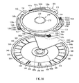
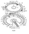
- a contact structure shown in Figs. 1A and 1B is used for detecting input of rotating and depressing operation in an input device (not shown).
- the contact structure includes a first movable contact 100 (a movable contact recited in the Claims), a second movable contact 200, a plurality of first fixed contacts 300, second fixed contacts 400a and 400b, lead wires 510, 521, and 522, and a cover 600.
- the first movable contact 100 and the first fixed contacts 300 constitute rotation detecting means for detecting input of rotating operation of a ring-like dial in the input device.
- the second movable contact 200 and the second fixed contacts 400a and 400b constitute depression detecting means for detecting input of a depressing operation of a pushbutton disposed inside the dial in the input device.
- the first fixed contacts 300, the second fixed contacts 400a and 400b, the lead wires 510, 521, and 522, and the cover 600 are formed on a first face of a circuit board of the input device.
- the first movable contact 100 is disposed on the first face of the circuit board so as to rotate on the first fixed contacts 300.
- the second movable contact 200 is mounted on the second fixed contact 400b on the first face of the circuit board.
- the first movable contact 100 is a ring-like metallic plate having electric conductivity. As shown in Figs. 1A , 1B , and 2 , the first movable contact 100 includes a base 110, arms 120a, 120b, 120c, and 120d (first, second, third, and fourth arms), and sliders 130a, 130b, 130c, and 130d (first, second, third, and fourth sliders).
- the base 110 is a plate including an annular ring 111 and four annular fixable portions 112.
- the fixable portions 112 are laid out at a pitch of 90° along the outer periphery of the ring 111.
- the fixable portions 112 can be fixed directly or indirectly to the dial of the input device. Fixing the fixable portions 112 of the base 110 to the dial allows the first movable contact 100 to rotate in a circumferential direction along the first fixed contacts 300 in accordance with the rotation of the dial.
- the arm 120a is an arcuate plate continuously connected to one of the fixable portions 112 of the base 110, and it slopes in the axial direction of the ring 111 (i.e., toward the first fixed contacts 300).
- the arm 120a is bifurcated into tips 121a and 122a.
- the arm 120c has the same shape as the arm 120a.
- the arms 120b and 120d have slightly different shapes from the arms 120a and 120c, as detailed below. As shown in Fig. 2 , the arm 120b is bifurcated into tips 121b and 122b, the arm 120c is bifurcated into tips 121c and 122c, and the arm 120d is bifurcated into tips 121d and 122d.
- the slider 130a has legs 131a and 132a (first legs) that are continuously connected to the tips 121a and 122a of the arm 120a to extend adjacent to each other in the radial direction of the ring 111.
- the legs 131a and 132a are plates of semi-arcuate shape projecting in the axial direction of the ring 111 (toward the first fixed contacts 300).
- the sliders 130b, 130c, and 130d have the same shape as that of the slider 130a.
- Fig. 2 also illustrate legs 131b and 132b of the slider 130b (second legs); legs 131c and 132c of the slider 130c (third legs); and legs 131d and 132d of the slider 130d (fourth legs).
- the legs 131a, 132a, 131b, 132b, 131c, 132c, 131d, and 132d can slide in the circumferential direction (hereinafter referred to as the "slide direction") on the first fixed contacts 300 on the first face of the circuit board in accordance with the rotation of the first movable contact 100.
- the legs 131a and 132a sliding on the first fixed contacts 300 on the first face of the circuit board form annular sliding tracks r1 and r2, respectively.
- the legs 131b and 132b sliding on the first fixed contacts 300 on the first face of the circuit board form annular sliding tracks r3 and r4, respectively.
- the sliding tracks r1, r2, r3 and r4 are illustrated as broken lines in Fig. 2 .
- the legs 131c and 132c form the same sliding tracks r1 and r2 as the legs 131a and 132a (the sliding tracks of the sliders 130a and 130c).
- the legs 131d and 132d form the same sliding tracks r3 and r4 as the legs 131b and 132b (the sliding tracks of the sliders 130b and 130d).
- the sliders 130a and 130c follow the same sliding tracks
- the sliders 130b and 130d follow the same sliding tracks.
- the arms 120a, 120b, 120c and 120d extend from the base 110 such that the sliding tracks r1 and r2 of the sliders 130a and 130c do not overlap the sliding tracks r3 and r4 of the sliders 130b and 130d.
- the arms 120a and 120c extend outwardly of the arms 120b and 120d in the radial direction, so that the sliding track r2 is positioned between the sliding tracks r3 and r4 while the sliding track r3 is positioned between the sliding tracks r1 and r2. For this reason the arms 120a and 120c are of different shape from the arms 120b and 120d.
- the second movable contact 200 is a metallic domed plate having electric conductivity.
- the second movable contact 200 includes a peripheral edge 210 and a top 220.
- the peripheral edge 210 is mounted on the second fixed contact 400b.
- the top 220 is disposed under the pushbutton of the input device to face the second fixed contact 400a.
- the second movable contact 200 is elastically deformed (i.e., reversed) toward the second fixed contact 400a and brought into contact with the second fixed contact 400a.
- the first fixed contacts 300 consists of three first signal contacts 310, three second signal contacts 320, three common contacts 330, and a plurality of dummy contacts 340 (including 340a and 340b).
- the first and second signal contacts 310 and 320, the common contacts 330, and the dummy contacts 340 are conductors annularly arranged with spacing along the sliding tracks r1 to r4 of the first face of the circuit board in the input device.
- the first and second signal contacts, the common contacts, and the dummy contacts are arranged counterclockwise in Fig.
- the first and second signal contacts 310 and 320 are connected to first lead wires (not shown), which are formed on the first face of the circuit board, on a second face opposite to the first face, and/or inside the circuit board.
- the first lead wires are connected to a control section in the input device.
- the common contacts 330 are connected to second lead wires (not shown), which are formed on the first and/or second faces and/or inside the circuit board.
- the second lead wires are grounded.
- the dummy contacts 340 (including 340a and 340b) are independent (i.e., connected to nothing). There is clearance left between the dummy contacts 340a and 340b.
- a predetermined voltage is applied to the first and second signal contacts 310 and 320.
- the first movable contact 100 rotates through the application of voltage to the first and second signal contacts 310 and 320, one of the sliders 130a, 130b, 130c, and 130d is brought into contact with one of the first signal contacts 310, while another one of the sliders 130a, 130b, 130c, and 130d is brought into contact with one of the common contacts 330. Consequently, a first pulse signal is outputted through the first lead wire connected to the contacted first signal contact 310.
- the control section can detect the rotational direction of the dial of the input device based on which of the first and second pulse signals is first inputted into the control section of the input device.
- control section counts the first and second pulse signals to detect the rotational amount (i.e., the rotational angle) of the dial.
- This is the mechanism how the first movable contact 100 and the first fixed contacts 300 function as the rotation detecting means for detecting the input of rotating operation in the input device.
- the second fixed contact 400a is a circular conductor disposed inside the first fixed contacts 300 on the first face of the circuit board.
- the second fixed contact 400b is a generally C-shaped conductor disposed concentrically with the second fixed contact 400a on the first face of the circuit board.
- the lead wire 510 is provided on the first face of the circuit board and connected to the second fixed contact 400a. The lead wire 510 extends from the second fixed contact 400a to the outside of the first fixed contacts 300 (i.e., to the outside of a virtual circle along the rim of the annually arranged first fixed contacts 300) through between the dummy contact 340a and the dummy contact 340b.
- the lead wires 521 and 522 are disposed on the first face of the circuit board to be connected to two ends of the second fixed contact 400b.
- the lead wires 521 and 522 extend from the second fixed contact 400b to the outside of the virtual circle through between the dummy contact 340a and the dummy contact 340b.
- the lead wires 510, 521, and 522 cross the sliding tracks r1 to r4.
- the lead wire 510 is connected to the control section of the input device, while the other lead wires 521 and 522 are grounded.
- the signal travels through the lead wire 510 to be received by the control section as indicating the input of the depressing operation of the depression button in the input device.
- This is the mechanism how the second movable contact 200 and the second fixed contacts 400a and 400b function as the depression detecting means for detecting the input of depressing operation in the input device.
- the cover 600 is an insulator or a resist provided on the first face of the circuit board.
- the cover 600 includes a fan-shaped cover body 610 and a ring-shaped annular portion 620.
- the cover body 610 covers the lead wires 510, 521, and 522 from the vicinity of the second fixed contact 400a to the outside of the virtual circle.
- the cover body 610 covers the portions of the lead wires 510, 521, and 522 that cross the sliding tracks r1 to r4.
- the cover body 610 also covers inner portions of the dummy contacts 340a and 340b.
- the annular portion 620 is continuous with the outer edge of the cover body 610 and is disposed concentrically and outside of the virtual circle of the first fixed contacts 300.
- the legs of the sliders 130a and 130c of the first movable contact 100 slide along the sliding tracks r1 and r2 on the first fixed contacts 300, and the legs of the sliders 130b and 130d slide along the sliding tracks r3 and r4 on the first fixed contacts 300, as shown in Fig. 4A.
- Fig. 4B shows a comparison example where the legs of four sliders slide along the same sliding tracks r5 and r6 on the first fixed contacts 300.
- the abrasion of the first fixed contacts 300 as shown in Fig. 4A should be reduced, substantially to half.
- the sliders 130a, 130b, 130c and 130d are arranged such that the sliding track r2 of the legs 132a and 132c is positioned between the sliding track r3 of the legs 131b and 131d and the sliding track r4 of the legs 132b and 132d, and the sliding track r3 of the legs 131b and 131d is positioned between the sliding track r1 of the legs 131a and 131c and the sliding track r2 of the legs 132a and 132c.
- the sliders 130a and 130c and the sliders 130b and 130d are arranged such that the traveling route of the sliders 130a and 130c partially overlaps that of the sliders 130b and 130d.
- the four sliders 130a, 130b, 130c and 130d are adapted to selectively contact the first and second signal contacts 310 and 320 and the common contacts 330 so as to output the first and second pulse signals. It is thus possible to reduce the number of first, second signal and common contacts, in comparison with a case where the three or less sliders selectively contact the first and second signal contacts and the common contacts. More particularly, given that the number of pulses of the first and second pulse signals is twelve and the movable contact has three sliders, then the required number of first, second signal and common contacts will be four. This is in contrast with the present contact structure with the first movable contact 100 including four sliders, then the required number of first and second signal contacts 310 and 320 and common contacts 330 is three.
- first and second signal contacts 310 and 320 and common contacts 330 By thus reducing the number of first and second signal contacts 310 and 320 and common contacts 330, it is possible to reduce the cost of the input device. Further advantageously, with the reduced number of first and second signal contacts 310 and 320 and common contacts 330, the lead wires 510, 521 and 522 can be readily lead out to the outside of the first fixed contacts 300 through between the adjacent two first fixed contacts 300.
- the above-described contact structure and the first movable contact 100 are not limited to the configurations of the above-described first preferred embodiment. They may be modified in design within the scope of the claims as described below in detail.
- the first movable contact 100 is a ring-like metallic plate adapted to rotate in the circumferential direction on the first fixed contacts 300.
- the first movable contact of the invention may be any movable contact adapted to move on the fixed contact or the resistor.
- a first movable contact may move straight on and along a straight fixed contact or resistor.
- a first movable contact may rotate on a ring-like resistor.
- the first movable contact 100 includes the base 110, the arms 120a, 120b, 120c and 120d, and the sliders 130a, 130b, 130c and 130d.
- the first movable contact of the invention may be modified in any manner as long as it is provided with first and second sliders arranged in such a manner as to slide on a fixed contact or a resistor, along different sliding tracks from each other in accordance with the movement of the movable contact.
- a first movable contact may be provided with a base and first and second sliders on the base arranged in such a manner as to slide along different sliding tracks from each other on a fixed contact or a resistor.
- the sliders 130a and 130b (the first and second sliders) follow the sliding tracks of annular shape.
- the sliding tracks of the first and second sliders of the invention are not limited to these.
- the sliding tracks of first and second sliders should be straight.
- the slider 130a (the first slider) has the legs 131a and 132a
- the slider 130b (the second slider) has the legs 131b and 132b.
- the first and second sliders of the invention may be modified in any manner as long as they are slidable along different sliding tracks from each other on a fixed contact or a resistor.
- each of the first and second sliders may have a single leg or three or more legs.
- each of the first and second sliders may also have a single leg, two legs as in first preferred embodiment, or three or more legs.
- the sliders 130a and 130c follow the same sliding tracks and the sliders 130b and 130d follow the same sliding tracks.
- the first, second, third and fourth sliders of the invention may be arranged such that they all follow different sliding tracks.
- the arms 120a and 120b are arcuate plates continuously connected to the fixable portions 112 of the base 110 and it slopes in the axial direction of the ring 111 (toward the first fixed contacts 300).
- the first and second arms of the invention may be modified in any manner as long as the first and second sliders are slidable along different sliding tracks from each other on a fixed contact or a resistor in accordance with movement of the movable contact.
- the base 110 includes the ring 111 and the four fixable portions 112.
- the base of the invention may be modified as long as it is adapted for provision of first and second arms or first and second sliders.
- first and second arms or first and second sliders may be provided in a disk-like base.
- the base may or may not be plate like, and it may also be evaporately deposited conductor on the dial or the like.
- the first fixed contacts 300 consist of the three first signal contacts 310, the three second signal contacts 320, the three common contacts 330, and the dummy contacts 340 (including the dummy contacts 340a and 340b).
- the first fixed contacts of the invention may be conductors of any kind allowing the first and second sliders to slide along different sliding tracks in accordance with the movement of the first movable contact.
- the dummy contacts 340 may be omitted.
- the contact structure is provided with the second movable contact 200, the second fixed contacts 400a and 400b, the lead wires 510, 521, and 522, and the cover 600.
- the contact structure of the present invention may not include any one of the second movable contact, the second fixed contacts, the lead wires, and the cover.
- the contact structure of the first preferred embodiment includes the depression detecting means for detecting the input of depressing operation in the input device constituted by the second movable contact 200 and the second fixed contacts 400a and 400b.
- the contact structure of the invention may be adapted for use with any other electronic device, in which case the second movable contact 200 may be omitted and the electronic device may be connected to the second fixed contacts 400a and 400b.
- the electronic device may be a light-emitting diode (LED), a line sensor for fingerprint authentication, a microphone, a proximity switch, or the like.
- the proximity switch may include a magnetic sensor for detecting changes in magnetic field in accordance with movement of a magnet fixed to the depression button, an electrostatic sensor for detecting changes in electrostatic capacity between a metallic plate and the sensor in accordance with movement of the metallic plate fixed to the depression button, or an optical sensor such as a photointerruptor.
- at least one second fixed contact will suffice.
- the second movable contact 200 or the electronic device as described above may be grounded using another connecting means such as a cable or a pin.
- the contact structure of the first preferred embodiment includes the lead wires 521 and 522 connected to the second fixed contact 400b. However, the lead wires 521 and 522 may be omitted. If omitted, the second fixed contact 400b may be connected to a common contact of the first fixed contacts.
- the lead wires 510, 521, and 522 are mounted on the first face of the circuit board in the first preferred embodiment, but the lead wires 510, 521, and 522 may be provided on and/or inside the first and second faces of a board. Additionally, the lead wires may extend from a second fixed contact to the outside of the first fixed contacts through between the dummy contact 340a and the dummy contact 340b, or through between any other adjacent two of the first fixed contacts.
- the second movable contact 200 in the first preferred embodiment is a domed metallic plate having the electric conductivity.
- the second movable contact of the invention may be modified as long as it is faces a second fixed contact and is adapted to elastically deform or move toward the second fixed contact so as to contact the second fixed contact.
- the second movable contact may be an electrically conductive plate having a semi-arcuate cross section.
- the cover 600 in the first preferred embodiment includes the cover body 610 and the annular portion 620.
- the cover of the invention may be of any other kind adapted to cover at least portions of the lead wires connected to the second fixed contact, the portions crossing the sliding tracks of the first and second sliders.
- each constituent element of the contact structure and the first movable contact may be modified as long as the same functions are achieved.
- the contact structure and the first movable contact of the invention may be used as detecting means for an input device or may be used for other purposes.
Landscapes
- Rotary Switch, Piano Key Switch, And Lever Switch (AREA)
- Contacts (AREA)
- Transmission And Conversion Of Sensor Element Output (AREA)
Applications Claiming Priority (1)
| Application Number | Priority Date | Filing Date | Title |
|---|---|---|---|
| JP2011259768A JP2013114886A (ja) | 2011-11-29 | 2011-11-29 | 可動接点及びこれを備えた接点構造 |
Publications (1)
| Publication Number | Publication Date |
|---|---|
| EP2600366A1 true EP2600366A1 (de) | 2013-06-05 |
Family
ID=47435829
Family Applications (1)
| Application Number | Title | Priority Date | Filing Date |
|---|---|---|---|
| EP20120250169 Withdrawn EP2600366A1 (de) | 2011-11-29 | 2012-11-09 | Beweglicher Kontakt und Kontaktstruktur damit |
Country Status (4)
| Country | Link |
|---|---|
| US (1) | US9035209B2 (de) |
| EP (1) | EP2600366A1 (de) |
| JP (1) | JP2013114886A (de) |
| CN (1) | CN103137346A (de) |
Families Citing this family (2)
| Publication number | Priority date | Publication date | Assignee | Title |
|---|---|---|---|---|
| US10424425B2 (en) * | 2016-04-27 | 2019-09-24 | Panasonic Intellectual Property Management Co., Ltd. | Resistance substrate and rheostat comprising same |
| CN108051017A (zh) * | 2018-03-20 | 2018-05-18 | 东莞市锁之道科技有限公司 | 一种旋转位置传感器 |
Citations (4)
| Publication number | Priority date | Publication date | Assignee | Title |
|---|---|---|---|---|
| DE19847429A1 (de) * | 1998-10-15 | 2000-05-04 | Klotz Digital Audio Communicat | Digitaler Schieberegler |
| JP2001148219A (ja) | 1999-11-19 | 2001-05-29 | Matsushita Electric Ind Co Ltd | 回転型エンコーダおよびこれを用いた複合操作型電子部品 |
| FR2884961A1 (fr) * | 2005-04-26 | 2006-10-27 | Valeo Systemes Thermiques | Bouton rotatif de commande d'une information de consigne variable, par mise en oeuvre d'un dispositif potentiometrique. |
| FR2933530A1 (fr) * | 2008-07-07 | 2010-01-08 | Sc2N Sa | Dispositif de commutation electrique et manette de commande sous-volant de vehicule correspondante |
Family Cites Families (15)
| Publication number | Priority date | Publication date | Assignee | Title |
|---|---|---|---|---|
| US4112274A (en) * | 1976-02-04 | 1978-09-05 | General Power Corp. | Electrical control |
| DE3040546C2 (de) * | 1980-10-28 | 1983-04-07 | Siemens AG, 1000 Berlin und 8000 München | Codierschalter |
| US4728755A (en) * | 1984-11-29 | 1988-03-01 | Robertshaw Controls Company | Rotary switch construction and method of making the same |
| JPH0742096Y2 (ja) * | 1990-10-26 | 1995-09-27 | 株式会社ニコン | エンコーダ |
| JP3665492B2 (ja) * | 1998-11-02 | 2005-06-29 | アルプス電気株式会社 | 回転型可変抵抗器 |
| EP1190830B1 (de) * | 1998-12-24 | 2004-07-14 | Teikoku Tsushin Kogyo Co. Ltd. | Verfahren zur Herstellung eines Schaltermusters auf einem Schaltersubstrat |
| JP3802998B2 (ja) * | 1999-07-26 | 2006-08-02 | 株式会社東海理化電機製作所 | ロータリスイッチ |
| JP3932778B2 (ja) * | 2000-07-11 | 2007-06-20 | 松下電器産業株式会社 | プッシュスイッチ付回転型エンコーダ |
| JP2004095242A (ja) * | 2002-08-30 | 2004-03-25 | Tsubame Musen Kk | ロータリーエンコーダ及びその基板製造方法 |
| JP4039251B2 (ja) * | 2003-01-16 | 2008-01-30 | 松下電器産業株式会社 | 回転型エンコーダ |
| JP4583743B2 (ja) * | 2003-06-16 | 2010-11-17 | 株式会社村田製作所 | クリック機構付き回転型可変抵抗器 |
| JP2005172596A (ja) * | 2003-12-10 | 2005-06-30 | Sony Corp | ロータリーエンコーダ及び携帯電話機 |
| US7030326B2 (en) * | 2003-12-30 | 2006-04-18 | Valeo Electrical Systems, Inc. | Digital wake-up signal from analog signal transition |
| JP4910883B2 (ja) * | 2007-05-25 | 2012-04-04 | パナソニック株式会社 | クリック付き回転操作型電子部品 |
| JP5281589B2 (ja) * | 2010-01-07 | 2013-09-04 | ホシデン株式会社 | 回転形パルススイッチ |
-
2011
- 2011-11-29 JP JP2011259768A patent/JP2013114886A/ja active Pending
-
2012
- 2012-11-09 EP EP20120250169 patent/EP2600366A1/de not_active Withdrawn
- 2012-11-27 CN CN2012104911796A patent/CN103137346A/zh active Pending
- 2012-11-28 US US13/687,215 patent/US9035209B2/en not_active Expired - Fee Related
Patent Citations (4)
| Publication number | Priority date | Publication date | Assignee | Title |
|---|---|---|---|---|
| DE19847429A1 (de) * | 1998-10-15 | 2000-05-04 | Klotz Digital Audio Communicat | Digitaler Schieberegler |
| JP2001148219A (ja) | 1999-11-19 | 2001-05-29 | Matsushita Electric Ind Co Ltd | 回転型エンコーダおよびこれを用いた複合操作型電子部品 |
| FR2884961A1 (fr) * | 2005-04-26 | 2006-10-27 | Valeo Systemes Thermiques | Bouton rotatif de commande d'une information de consigne variable, par mise en oeuvre d'un dispositif potentiometrique. |
| FR2933530A1 (fr) * | 2008-07-07 | 2010-01-08 | Sc2N Sa | Dispositif de commutation electrique et manette de commande sous-volant de vehicule correspondante |
Also Published As
| Publication number | Publication date |
|---|---|
| CN103137346A (zh) | 2013-06-05 |
| JP2013114886A (ja) | 2013-06-10 |
| US20130134030A1 (en) | 2013-05-30 |
| US9035209B2 (en) | 2015-05-19 |
Similar Documents
| Publication | Publication Date | Title |
|---|---|---|
| US10483057B2 (en) | Input device | |
| US8344834B2 (en) | Input apparatus | |
| US7019765B2 (en) | Input device | |
| CN101641571B (zh) | 旋转输入装置及使用该旋转输入装置的旋转检测装置 | |
| US8928308B2 (en) | Current sensor | |
| US8918548B2 (en) | System method for accessory adapter with power supplying capabilities wherein power conductive element is either active or passive depending on placement of electrical contacts | |
| US8307720B2 (en) | Device for determining a torque and/or a rotational angle of a shaft | |
| JP2016051501A (ja) | 回転操作型電気部品 | |
| US20130342222A1 (en) | Rotary input apparatus | |
| JP2013228855A (ja) | タッチパネル | |
| EP2600366A1 (de) | Beweglicher Kontakt und Kontaktstruktur damit | |
| US4748861A (en) | Electronic display measuring device | |
| US6856261B2 (en) | Rotary encoder | |
| JP7225398B2 (ja) | 入力装置 | |
| JP2005072300A (ja) | 可変抵抗器 | |
| US12189873B2 (en) | Input device and input system | |
| JP5843402B2 (ja) | スイッチ装置用の操作装置、および、スイッチ装置 | |
| KR100875007B1 (ko) | 입력 장치 | |
| CN114624494A (zh) | 分割型传感器头和分割型电流传感器 | |
| CN203812776U (zh) | 按键用焊盘、按键、按键开关、便携设备 | |
| JPH0565025U (ja) | クリック感触付きロータリスイッチ | |
| US20260036442A1 (en) | Input device and rotation detection device of the same | |
| JP6456803B2 (ja) | 入力装置 | |
| JP2951087B2 (ja) | ロータリエンコーダ | |
| JPH085311A (ja) | 接触式ロータリーエンコーダ |
Legal Events
| Date | Code | Title | Description |
|---|---|---|---|
| PUAI | Public reference made under article 153(3) epc to a published international application that has entered the european phase |
Free format text: ORIGINAL CODE: 0009012 |
|
| AK | Designated contracting states |
Kind code of ref document: A1 Designated state(s): AL AT BE BG CH CY CZ DE DK EE ES FI FR GB GR HR HU IE IS IT LI LT LU LV MC MK MT NL NO PL PT RO RS SE SI SK SM TR |
|
| AX | Request for extension of the european patent |
Extension state: BA ME |
|
| 17P | Request for examination filed |
Effective date: 20131204 |
|
| RBV | Designated contracting states (corrected) |
Designated state(s): AL AT BE BG CH CY CZ DE DK EE ES FI FR GB GR HR HU IE IS IT LI LT LU LV MC MK MT NL NO PL PT RO RS SE SI SK SM TR |
|
| STAA | Information on the status of an ep patent application or granted ep patent |
Free format text: STATUS: THE APPLICATION HAS BEEN WITHDRAWN |
|
| 17Q | First examination report despatched |
Effective date: 20150423 |
|
| 18W | Application withdrawn |
Effective date: 20150421 |