EP2596772B1 - Nagelspange, Nagelspangenapplikator und Applikationsset - Google Patents
Nagelspange, Nagelspangenapplikator und Applikationsset Download PDFInfo
- Publication number
- EP2596772B1 EP2596772B1 EP12190646.5A EP12190646A EP2596772B1 EP 2596772 B1 EP2596772 B1 EP 2596772B1 EP 12190646 A EP12190646 A EP 12190646A EP 2596772 B1 EP2596772 B1 EP 2596772B1
- Authority
- EP
- European Patent Office
- Prior art keywords
- nail
- nail brace
- nail clip
- strip
- applicator
- Prior art date
- Legal status (The legal status is an assumption and is not a legal conclusion. Google has not performed a legal analysis and makes no representation as to the accuracy of the status listed.)
- Active
Links
Images


Classifications
-
- A—HUMAN NECESSITIES
- A61—MEDICAL OR VETERINARY SCIENCE; HYGIENE
- A61F—FILTERS IMPLANTABLE INTO BLOOD VESSELS; PROSTHESES; DEVICES PROVIDING PATENCY TO, OR PREVENTING COLLAPSING OF, TUBULAR STRUCTURES OF THE BODY, e.g. STENTS; ORTHOPAEDIC, NURSING OR CONTRACEPTIVE DEVICES; FOMENTATION; TREATMENT OR PROTECTION OF EYES OR EARS; BANDAGES, DRESSINGS OR ABSORBENT PADS; FIRST-AID KITS
- A61F5/00—Orthopaedic methods or devices for non-surgical treatment of bones or joints; Nursing devices ; Anti-rape devices
- A61F5/01—Orthopaedic devices, e.g. long-term immobilising or pressure directing devices for treating broken or deformed bones such as splints, casts or braces
- A61F5/11—Devices for correcting deformities of the nails
Definitions
- the invention relates to a nail clip for making nail corrections. Further, the invention is directed to a Nagelspangenapplikator for application of the nail clip on a nail of a toe or a finger and on a set for making nail corrections, comprising the nail clip and the Nagelspangenapplikator.
- Nail clips are from the EP 0 282 645 B1 basically known.
- the nail clip according to the EP 0 282 645 B1 in the form of a leaf spring-like strip is used to laterally lift a too-curved nail.
- the nail clip is a strip of elastic plastic and is glued by means of a quick glue with the nail to be corrected.
- a Nagelspangenapplikator is described, which is used for the defined positioning and fixing of the nail clip.
- This special tool has an elongated base body with an approximately perpendicular to the longitudinal direction end face on which the nail clip to be applied can be releasably held with a support member.
- the support member is designed as a rubber-elastic sleeve in the manner of a rubber ring and slidable for fixing the nail clip on a mounting lug of Nagelspangenapplikators.
- the holding element encloses, in addition to the holder attachment, the nail clip placed on the application surface at one longitudinal end thereof.
- This nail clasp applicator has proven itself in practice. Nevertheless, the application of the nail brace requires a certain amount of skill even with its help, in particular for pushing the retaining element on the Nagelspangenapplikator and thus for releasable fixation of the nail clip on this.
- the invention is also based on the object to provide a set for making nail corrections with a corresponding nail clip and a corresponding Nagelspangenapplikator.
- the nail clip has a covering, which is provided on the strip at least in regions, which contains a magnetic material, while the nail clip applicator comprises a magnetic holding element, in particular in the form of a permanent magnet.
- the magnetic material provided for the covering of the strip may in particular be a magnetic or magnetizable material.
- a nail clip is then particularly easy to attach to the Nagelspangenapplikator when the nail clip contains a coating of magnetic material that interacts with the magnetic support member of Nagelspangenapplikators. Additional fasteners can then be omitted.
- the covering is detachably provided on the leaf-spring-like strip of the nail clip. This ensures that the coating after application of the nail clip on the nail to be treated is again removed from the leaf spring-like strip of the nail clip.
- the nail clip is preferably transparent, and can be seen on the nail only by closer inspection. If the covering comprising the magnetic material stands out in color from the nail clip, it is expedient for aesthetic reasons to detach the covering again from the nail clip after application of the nail clip.
- the pad extends adjacent to a central transverse axis of the leaf spring-like strip.
- the coating is designed as a lacquer to which the magnetic material is admixed. It is then in particular a (magnetic) metal paint before. Preferably, it can also be a nail polish in the paint act.
- a nail polish in the paint act.
- Nail varnish mainly consists of nitrocellulose, solvents and possibly color pigments.
- Such a nail polish has a high adhesion and high durability. It can be easily applied to the leaf-spring-like strip of the nail clip. In addition, it is available virtually everywhere and thus has a high availability.
- the covering is designed as an adhesive strip, which comprises the ferromagnetic material and which is glued to the leaf spring-like strip.
- This design of the covering as adhesive strip can be dispensed with additional aids for applying the coating on the nail clip.
- the adhesive strip can be glued by hand, for example, on the nail clip.
- the adhesive material can be chosen so that a redetachment of the adhesive strip from the nail clip after applying the nail clip on the nail is easily possible.
- the magnetic material according to a further advantageous embodiment comprises a ferromagnetic material and in particular at least one element of the group consisting of iron, nickel and cobalt, ensures that the nail clip can be easily grasped by a Nagelspangenapplikator with a magnetic support member.
- iron, nickel and / or cobalt high magnetic holding forces can be achieved under normal conditions.
- a further advantageous variant according to claim 7 provides that the magnetic material is particulate, and in particular with an average particle size in the range between 5 microns and 100 microns, is formed. Due to the particulate design of the magnetic material this can be mixed in a simple manner largely arbitrary substances, which are then applied as a coating on the nail clip. However, it is also possible in principle to apply the particulate magnetic material directly on the nail clip.
- the leaf-spring-like strip consists of a multilayer glass fiber reinforced thermosetting plastic, which in particular comprises three glass fiber layers.
- a multilayer glass fiber reinforced thermosetting plastic which in particular comprises three glass fiber layers.
- Such a design is particularly advantageous because between plastic and human nails by means of instant adhesive a very effective and extremely durable compound can be made.
- the stiffness of the nail clip is increased over a single-layer design. This has the advantage that the restoring force of the leaf-spring-like strip is increased, whereby the effect of the nail clip is further improved.
- the support member of the Nagelspangenapplikators is disposed substantially adjacent to a central-transverse axis of an application surface of the Nagelspangenapplikators on the application surface, it is possible that the nail clip centered on the application surface can be applied.
- the pad material of the nail clip comprising the magnetic material extends adjacent to the mid-transverse axis of the nail clip and the magnetically-shaped support member adjacent to the mid-transverse axis of the application surface of the nail clip applier, the application surface and nail clip are adjacent to a common middle clip. Transverse axis in contact brought, whereby a stable support of the nail clip on the application surface is made possible.
- the support member of the Nagelspangenapplikators is arranged in a recess of the application surface. By this arrangement, a secure fixation of the support member is achieved on the application surface.
- the arrangement according to claim 12 makes it possible that the holding element does not protrude beyond the application area and thus a substantially flat application surface is provided.
- the design according to claim 13 creates the possibility that the covering of the nail clip can dip into a first residual recess of the application surface. This results in an additional positive connection between the residual recess of the application surface and the covering of the nail clip. In addition, a flush fit of the nail clip on the application surface is thus made possible and the nail clip securely held on the first application surface even with a coating with a certain coating thickness.
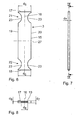
- Fig. 1 is an embodiment of a set 1 for making nail corrections comprising a strip-shaped and leaf-spring-like nail clip 2 and a Nagelspangenapplikator 3 for application of the nail clip 2 on a nail 4 of a toe or finger (see Fig. 11 to Fig. 13 ).
- the nail clip 2 is used for sticking to a nail to be treated 4 of a toe or a finger, while the nail clip applicator 3 is used to apply the nail clip 2 on the nail 4.
- the nail clip 2 comprises according to the Fig. 2 and Fig. 3 a leaf spring-like strip 5 made of elastic plastic with a central-transverse axis 6, which is transverse to the longitudinal extent of the strip 5, an upper side 7, a lower side 8, two longitudinal edges 9, 10 and two spaced to the central transverse axis 6 lying edge regions 11, 12.
- the leaf-spring-like strip 5 is with respect to a through the central-transverse axis 6 going Middle plane formed substantially symmetrical and has a clasp length d 1 and a clasp width d 2 .
- the nail clip 2 may have another dimension depending on the nail 4 to be corrected of a toe or a finger. This is especially true for their clasp length d 1 , which varies depending on the application.
- clasp length d 1 varies depending on the application.
- These different clasp lengths d 1 can z. B. in a set 1 with a variety of part but also different length nail clips 2 may be provided. In principle, however, other clasp lengths d 1 are possible.
- a releasable covering 13 is provided at least in regions, which contains a ferromagnetic material 14.
- the ferromagnetic material 14 is preferably iron, nickel or cobalt. The elements mentioned have particularly good ferromagnetic properties at room temperature.
- the pad 13 is thinly applied to the top 7 of the leaf spring-like strip 5 and extends in the central region of the strip 5 adjacent to the central transverse axis 6.
- the pad 13 is preferably such a thin layer applied to the top 7 of the leaf spring-like strip 5, that the Top 7 a substantially flat surface, without noticeable elevations forms.
- the pad 13 has a relation to the Clasp length d 1 shorter longitudinal extent d 3 on.
- the transverse extent d 4 of the lining 13 corresponds essentially to the clasp width d 2 ; at least the transverse extent d 4 preferably covers at least 3 ⁇ 4 of the clasp width d 2 . But it can also be equal to the clasp width d 2 .
- the coating 13 is formed as a lacquer to which the ferromagnetic material 14 is admixed. Due to its good adhesive properties, a nail varnish to which iron, nickel and / or cobalt-containing particles are admixed is particularly suitable. Trained as a varnish coating 13 is releasably applied to the leaf-spring-like strip 5 of the nail clip 2 and has a different color design to the leaf-spring-like strip 5. The different color design serves to clearly identify the covering 13 containing the ferromagnetic material 14, so that it can be easily identified by a user and the user recognizes where the nail clip applicator 3 is to be attached to the nail clip 2.
- the leaf-spring-like strip 5 of the nail clip 2 is formed of an intrinsically elastic plastic, preferably of a multilayer glass fiber reinforced thermosetting plastic, which in particular comprises three glass fiber layers.
- a plastic preserves, not least because of the three-layer glass fiber reinforcement, even if it is designed as a very thin strip, for a long time its own elasticity.
- PE polyethylene
- Adjacent to its two each extending approximately perpendicular to the central longitudinal axis 16 end faces 17, 18 of the base body 15 each have an application zone 21, 22.
- the application zones 21, 22 include not only designed as application surfaces end faces 17, 18 but also at least one In the preferred embodiment, each application zone 21, 22 exactly two part-circular recesses 23.
- the recesses 23 are in the application zones 21, 22 with respect to the central longitudinal -Axis 16 opposite each other on the longitudinal sides 19, 20 are provided.
- main body 15 is alternatively provided only with an application zone 21 which extends adjacent to the end face 17.
- application zone 21 which extends adjacent to the end face 17.
- the application zones 21, 22 are substantially identical in construction and in particular also symmetrical to a central-transverse axis 27 of the main body, which runs substantially perpendicular to the central longitudinal axis 16. Due to the substantially identical construction of the application zones 21 and 22 is in the Fig. 11 to Fig. 13 by way of example, only one section of the nail clasp applicator 3 comprising the application zone 21 is shown.
- the application surface lengths d 5 and d 6 of the application surfaces 17 and 18, respectively, which extend substantially parallel to the central transverse axis 27 are different from one another.
- the application surface length d 5 is 20 mm and is thus larger than the application surface d 6 , which has an extension of 18 mm.
- Other length combinations d 5 / d 6 are also possible in principle.
- the application surface width d 7 of the application surfaces 17, 18 in the preferred first embodiment is 3 mm in each case. Other application surface widths are also possible in principle.
- the application surfaces 17, 18 are adapted in their extension to the respective extensions d 1 , d 2 of the nail clip 2 to be applied.
- the application surface length d 5 , d 6 corresponds to the respective clasp length d 1
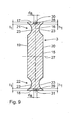
- a support member 28, 29 is provided for releasably holding the nail clip 2 to be applied.
- the support members 28, 29 are magnetically formed, preferably as permanent magnets. Iron, nickel, cobalt, neodymium and / or a ferrite are particularly suitable as material for the holding elements 28, 29 designed as permanent magnets. Likewise, compounds or alloys with one or more of these materials are possible.
- Each holding element 28, 29 extends substantially adjacent to the central longitudinal axis 16 on the application surfaces 17, 18.
- the longitudinal extent d 8 of the holding elements 28, 29 is significantly smaller than the application surface lengths d 5 , d 6 .
- the width d 9 of the support members 28, 29 is less than the application surface width d. 7
- the support members 28, 29 respectively in recesses 30, 31 of the application surfaces 17, 18 are arranged.
- the recesses 30, 31 extend within the base body 15 along the central longitudinal axis 16 of the application surfaces 17, 18 away in the direction of the central-transverse axis 27. They are arranged approximately centrally to the central longitudinal axis 16.
- the recesses 30, 31 are viewed rectangular in section and adapted to the dimensions of the support members 28, 29.
- the length and the width of the recesses 30, 31 corresponds essentially to the dimensions d 8 , d 9 of the support elements 28, 29.
- the depth t 1 of the recesses 30, 31 corresponds in the preferred embodiment, at least the height h 1 of the support members 28, 29.
- the support members 28, 29 are fixed either by positive engagement in the recess 30, 31, or alternatively by means of a adhesive bond.
- the support members 28, 29 are inserted completely into the recesses 30, 31 in the preferred embodiment.
- the recesses 30, 31 preferably have a depth t 1 , which corresponds to the height h 1 of the support members 28, 29.
- the application surfaces 17, 18 thus form a flat surface which can be brought into contact with the nail clip 2.
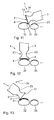
- the nail 4 of a toe is to be corrected, which is too curved in particular in the region of its lateral outer edges and accordingly not only unattractive to look at, but also pain-causing.
- 12 and 13 is the sequence of application of the nail clip 2 on the nail 4 with the aid of Nagelspangenapplikators 3 shown.
- the toe to be treated 32 and the neighboring toe 33 are shown in a front view.
- the Nagelspangenapplikator 3 comes before the actual in the 11, 12 and 13 Application process shown used. It can be used with advantage also for determining the required for the nail 4 to be treated clasp length d 1 . Since the application surface lengths d 5 , d 6 are equal to one of the available clasp lengths d 1 , the nail clasp applicator 3 can be used to size the nail 4 to be treated. On the basis of the application surface length d 5 or d 6 , which has the best match with the width of the nail 4 to be treated, the nail clip 2 most suitable in this case is selected. From the plurality of available nail clips 2, each with a different clasp length d 1 , that is selected which, for example, has a spacing of approximately 1 mm from the lateral nail wall.
- the nail clip 2 selected in this way is fixed on the application surface 17 or 18 of the nail clip applier 3 belonging to this clip length d 1 on account of magnetic attraction.
- the first application zone 21 is used.
- the covering 13 contains ferromagnetic material 14
- the nail clip 2 can be gripped in a particularly simple manner by the holding element 28 of the nail clip applicator 3 designed as a permanent magnet.
- the nail clip applicator 3 with its first application surface 17 is to be brought close to the covering 13 of the nail clip 2.
- the nail clip 2 is stored, for example, in a nail clip storage device, not shown, in which there are a variety of nail clips 2 also with different sizes.
- the covering 13 rests on the recess 30, the covering 13 preferably being in contact with the holding element 28 located in the recess 30.
- the nail clip 2 is achieved exclusively by the magnetic interaction between the magnetic support member 28 and the ferromagnetic material 14 having coating 13.
- the nail clip 2 is coated on the side facing away from the Nagelspangenapplikator 3 underside 8 with a quick adhesive.
- the adhesive can also be applied to the nail 4 to be treated.
- the nail-clasp applicator 3 may under certain circumstances tilt very far in the direction of the adjacent toe 33.
- the recess 21 is provided on the longitudinal side 19 of the Nagelspangenapplikators 3, which faces the Nachbarzehe 33 in this situation.
- the recess 21 provides a free space for the Nachbarzehe 33 (see. Fig. 11 ).
- the edge region 11 of the nail clip 2 is pressed by means of the Nagelspangenapplikators 3 as long as the lateral outer edge of the nail 4 until the instant adhesive has set so far that the nail clip 2 is fixed there on the nail 4. This is followed by a first pivoting movement of the Nagelspangenapplikators 3 to the center of the nail 4, ie in the direction of the arrow 34 (see Fig. 11 ). Once in this center position, the nail clip 2 is again pressed by means of the nail clip applicator 3 in this position on the nail 4 until the adhesive force effect is also present here (see Fig. 12 ).
- the support member 28 formed as a permanent magnet should preferably be chosen so that the magnetic attraction between the pad 13 and the support member 28 is less than the adhesive force between the nail 4 and the bottom 8 of the leaf spring-like strip 5 of the nail clip. 2
- the set 1 with the nail clip 2 and the Nagelspangenapplikator 3 facilitates the application of the nail clip 2 on a nail 4 considerably. Due to the magnetic interaction between Nagelspangenapplikator 3 and nail clip 2 no retaining elements are necessary, which must be attached with laborious manual work on the nail clip 2 and the Nagelspangenapplikator 3, and hold the nail clip 2 on the Nagelspangenapplikator. The treating podiatrist does not even have to grasp the nail clip 2, since the nail clip 2 is gripped by the magnetic interaction with the nail clip applicator 3.
- Fig. 14 shows a second variant of a set 35 with a second embodiment of a nail clip 36 according to the Fig. 4, Fig. 5 , and a second embodiment of a Nagelspangenapplikator 37.
- Components that correspond to those described above with reference to the Fig. 1 to Fig. 13 have the same reference numbers and will not be discussed again in detail.
- the nail clip 36 differs from the nail clip 2 only by the design of the pad 38.
- the pad 38 which contains the ferromagnetic material 14 is formed as an adhesive strip and has a height d 10 on.
- the pad 38 according to Fig. 4, Fig. 5 and Fig. 14 preferably comprises a substantially rectangular body 39 made of ferromagnetic material, such as iron, nickel or cobalt.
- the pad 38 is glued in the second embodiment of the nail clip 36 on the leaf spring-like strip 5.
- the Nagelspangenapplikator 37 according to Fig. 14 differs from the Nagelspangenapplikator 3 by the arrangement of the support members 28, 29 in the recesses 30, 31.
- the in Fig. 14 illustrated insertion position of the support member 28, 29 is provided on the application surfaces 17, 18 each have a residual recess 40, 41.
- the residual recesses 40, 41 are generated in that the height h 1 of the support elements 28, 29 is less than the depth t 1 of the recesses 30, 31st
- the Restausnatural insects 40, 41 are used when applying the Nagelspange 36 using the Nagelspangenapplikators 37 for cooperation with the pad 38th
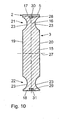
- Fig. 15 shows a third variant of a Nagelspangenapplikators 42.
- Components that correspond to those already described above with reference to the Fig. 1 to Fig. 14 have the same reference numbers and will not be discussed again in detail.
- the Nagelspangenapplikator 42 has approximately the shape of a pencil and comprises a longitudinally extending elongated base body 43, the first end face 44 is round and is provided with an inwardly extending recess 45 into which a support member 46 is inserted.
- the support member 46 is used for releasably holding the nail clip 2 to be applied and is magnetically formed, preferably as a permanent magnet.
- As the material for the support member 46 formed as a permanent magnet iron, nickel, cobalt or ferrites are particularly suitable according to the support members 28, 29.
- the recess 45 preferably has a depth which is greater than a height of the support member 46, so that when inserted support member 46 at the application surface 44 a Restaus originallyung 48 is present, which can cooperate with a correspondingly shaped pad 38 of the nail clip 36.
- the second end face 47 of the Nagelspangenapplikators 42 is formed in the form of a small spatula and is suitable for applying the adhesive to the nail clip 2 or the nail 4.
Landscapes
- Health & Medical Sciences (AREA)
- Nursing (AREA)
- Orthopedic Medicine & Surgery (AREA)
- Engineering & Computer Science (AREA)
- Biomedical Technology (AREA)
- Heart & Thoracic Surgery (AREA)
- Vascular Medicine (AREA)
- Life Sciences & Earth Sciences (AREA)
- Animal Behavior & Ethology (AREA)
- General Health & Medical Sciences (AREA)
- Public Health (AREA)
- Veterinary Medicine (AREA)
- Orthopedics, Nursing, And Contraception (AREA)
- Medicinal Preparation (AREA)
- Cosmetics (AREA)
Priority Applications (1)
| Application Number | Priority Date | Filing Date | Title |
|---|---|---|---|
| PL12190646T PL2596772T3 (pl) | 2011-11-25 | 2012-10-30 | Klamra na paznokcie, aplikator klamry na paznokcie oraz zestaw do aplikacji |
Applications Claiming Priority (1)
| Application Number | Priority Date | Filing Date | Title |
|---|---|---|---|
| DE102011087144A DE102011087144B4 (de) | 2011-11-25 | 2011-11-25 | Nagelspange, Nagelspangenapplikator und Applikationsset |
Publications (2)
| Publication Number | Publication Date |
|---|---|
| EP2596772A1 EP2596772A1 (de) | 2013-05-29 |
| EP2596772B1 true EP2596772B1 (de) | 2014-05-21 |
Family
ID=47143627
Family Applications (1)
| Application Number | Title | Priority Date | Filing Date |
|---|---|---|---|
| EP12190646.5A Active EP2596772B1 (de) | 2011-11-25 | 2012-10-30 | Nagelspange, Nagelspangenapplikator und Applikationsset |
Country Status (7)
Cited By (3)
| Publication number | Priority date | Publication date | Assignee | Title |
|---|---|---|---|---|
| DE202023105639U1 (de) | 2023-09-27 | 2025-01-08 | Bernd Stolz | Nagelspangenapplikator zur Nagelspangenapplikation |
| DE102023209249A1 (de) | 2023-09-21 | 2025-03-27 | Bernd Stolz | Nagelspangenapplikator und Verfahren zur Nagelspangenapplikation |
| WO2025061421A1 (de) | 2023-09-21 | 2025-03-27 | Bernd Stolz | Nagelspangenapplikator zur nagelspangenapplikation |
Families Citing this family (3)
| Publication number | Priority date | Publication date | Assignee | Title |
|---|---|---|---|---|
| JP2015164833A (ja) * | 2014-02-05 | 2015-09-17 | 株式会社マルイ | 自転車用サドルとその製造方法 |
| KR200493704Y1 (ko) | 2021-02-23 | 2021-05-24 | 주식회사 킹케어 | 내향성 손발톱 교정 스트립 |
| KR102379870B1 (ko) | 2021-11-01 | 2022-03-30 | 주식회사 킹케어 | 밴드형 내향성 손발톱 교정 스트립 |
Family Cites Families (9)
| Publication number | Priority date | Publication date | Assignee | Title |
|---|---|---|---|---|
| US4057055A (en) * | 1975-08-22 | 1977-11-08 | Clark John H | Toenail appliance and method |
| DE3708811A1 (de) | 1987-03-18 | 1988-09-29 | Bernd Stolz | Verfahren und vorrichtung zur vornahme von nagelkorrekturen |
| JPH0626287Y2 (ja) * | 1992-04-06 | 1994-07-20 | 秀夫 矢野 | 磁気治療貼り薬の貼付器具 |
| JP3519858B2 (ja) * | 1996-03-21 | 2004-04-19 | 古河電気工業株式会社 | 陥入爪矯正具 |
| JP3474998B2 (ja) * | 1996-03-21 | 2003-12-08 | 古河電気工業株式会社 | 陥入爪矯正具 |
| KR200335630Y1 (ko) | 2003-07-21 | 2003-12-11 | 주식회사 에프에스코리아 | 자석이 내장된 손톱 손질용 에머리 보드 |
| JP2009531080A (ja) * | 2006-03-09 | 2009-09-03 | リベルソン,アハロン | 陥入爪治療用のデバイス及びその方法 |
| US20090078277A1 (en) * | 2006-05-08 | 2009-03-26 | Fumiko Uemura | Nail Shaper for Ingrown Nail and False Nail |
| DE102008010442B3 (de) * | 2008-02-21 | 2009-07-30 | Bernd Stolz | Nagelspangenapplikator |
-
2011
- 2011-11-25 DE DE102011087144A patent/DE102011087144B4/de not_active Expired - Fee Related
-
2012
- 2012-10-30 ES ES12190646.5T patent/ES2491817T3/es active Active
- 2012-10-30 EP EP12190646.5A patent/EP2596772B1/de active Active
- 2012-10-30 PL PL12190646T patent/PL2596772T3/pl unknown
- 2012-11-12 JP JP2012248282A patent/JP5744820B2/ja active Active
- 2012-11-23 CN CN201210482798.9A patent/CN103126795B/zh active Active
- 2012-11-23 KR KR20120133753A patent/KR101487581B1/ko active Active
Cited By (3)
| Publication number | Priority date | Publication date | Assignee | Title |
|---|---|---|---|---|
| DE102023209249A1 (de) | 2023-09-21 | 2025-03-27 | Bernd Stolz | Nagelspangenapplikator und Verfahren zur Nagelspangenapplikation |
| WO2025061421A1 (de) | 2023-09-21 | 2025-03-27 | Bernd Stolz | Nagelspangenapplikator zur nagelspangenapplikation |
| DE202023105639U1 (de) | 2023-09-27 | 2025-01-08 | Bernd Stolz | Nagelspangenapplikator zur Nagelspangenapplikation |
Also Published As
| Publication number | Publication date |
|---|---|
| PL2596772T3 (pl) | 2014-10-31 |
| DE102011087144A1 (de) | 2013-05-29 |
| CN103126795B (zh) | 2016-01-20 |
| JP5744820B2 (ja) | 2015-07-08 |
| KR20130058634A (ko) | 2013-06-04 |
| ES2491817T3 (es) | 2014-09-08 |
| KR101487581B1 (ko) | 2015-01-29 |
| CN103126795A (zh) | 2013-06-05 |
| EP2596772A1 (de) | 2013-05-29 |
| DE102011087144B4 (de) | 2013-09-19 |
| JP2013111477A (ja) | 2013-06-10 |
Similar Documents
| Publication | Publication Date | Title |
|---|---|---|
| EP2596772B1 (de) | Nagelspange, Nagelspangenapplikator und Applikationsset | |
| DE102010030813B4 (de) | Vorrichtung zum Auftragen eines magnetische Teilchen enthaltenden Kosmetikprodukts und die Vorrichtung enthaltende Einheit | |
| DE202010014791U1 (de) | Rechteckiger Abstreifer für Flachbürsten | |
| DE69610418T2 (de) | Pinsel mit borstenzwinge | |
| DE2402785A1 (de) | Am buerstenkopf einer zahnbuerste angebrachte weichelastische massageflaeche fuer das zahnfleisch | |
| DE2428782A1 (de) | Selbstklebender verschluss | |
| DE102007051509A1 (de) | Mophalter sowie zugehöriger Mopbezug | |
| EP3337359A1 (de) | Haltekörper, haltevorrichtung und verfahren zur montage einer haltevorrichtung | |
| EP0282645B1 (de) | Vorrichtung zur Vornahme von Nagelkorrekturen | |
| DE102008010442B3 (de) | Nagelspangenapplikator | |
| DE102015100323B4 (de) | Vorrichtung zur Nagelkorrektur | |
| DE102008053905A1 (de) | Gerät zum Auftragen eines flüssigen, gelartigen, pastösen oder pulverförmigen Produkts | |
| DE102017104744A1 (de) | Universalschieber zur Bodenreinigung | |
| EP0119577B1 (de) | Haarkamm aus Kunststoff | |
| DE102018114692B4 (de) | Malerpinsel mit nicht endseitig befestigten Borstenbündeln | |
| DE102020105490A1 (de) | Duschablage | |
| DE102014213604A1 (de) | Dosierkappe | |
| DE8611436U1 (de) | Kraftfahrzeug mit Zusatzprofilteilen aus Kunststoff | |
| DE202008014451U1 (de) | Gerät zum Auftragen eines flüssigen, gelartigen, pastösen oder pulverförmigen Produkts | |
| DE10164742B4 (de) | Produkt zum Befestigen von Kanülen, Schläuchen oder Elektroden | |
| EP0211018B1 (de) | Halter für werkzeuge und geräte | |
| EP4551169A1 (de) | Nagelspangenapplikator zur nagelspangenapplikation | |
| DE102014109467A1 (de) | Halteteil, flächige Schutzeinrichtung sowie Verfahren zur Herstellung von Halteteil und Schutzeinrichtung | |
| DE9406286U1 (de) | Halterung für eine Rolle mit abrollbarem Material | |
| DE102009052635A1 (de) | Doppelseitiges Klebekissen |
Legal Events
| Date | Code | Title | Description |
|---|---|---|---|
| PUAI | Public reference made under article 153(3) epc to a published international application that has entered the european phase |
Free format text: ORIGINAL CODE: 0009012 |
|
| AK | Designated contracting states |
Kind code of ref document: A1 Designated state(s): AL AT BE BG CH CY CZ DE DK EE ES FI FR GB GR HR HU IE IS IT LI LT LU LV MC MK MT NL NO PL PT RO RS SE SI SK SM TR |
|
| AX | Request for extension of the european patent |
Extension state: BA ME |
|
| 17P | Request for examination filed |
Effective date: 20130605 |
|
| RBV | Designated contracting states (corrected) |
Designated state(s): AL AT BE BG CH CY CZ DE DK EE ES FI FR GB GR HR HU IE IS IT LI LT LU LV MC MK MT NL NO PL PT RO RS SE SI SK SM TR |
|
| GRAP | Despatch of communication of intention to grant a patent |
Free format text: ORIGINAL CODE: EPIDOSNIGR1 |
|
| RIC1 | Information provided on ipc code assigned before grant |
Ipc: A61F 5/11 20060101AFI20131212BHEP |
|
| INTG | Intention to grant announced |
Effective date: 20140116 |
|
| GRAS | Grant fee paid |
Free format text: ORIGINAL CODE: EPIDOSNIGR3 |
|
| GRAA | (expected) grant |
Free format text: ORIGINAL CODE: 0009210 |
|
| AK | Designated contracting states |
Kind code of ref document: B1 Designated state(s): AL AT BE BG CH CY CZ DE DK EE ES FI FR GB GR HR HU IE IS IT LI LT LU LV MC MK MT NL NO PL PT RO RS SE SI SK SM TR |
|
| REG | Reference to a national code |
Ref country code: GB Ref legal event code: FG4D Free format text: NOT ENGLISH |
|
| REG | Reference to a national code |
Ref country code: CH Ref legal event code: EP |
|
| REG | Reference to a national code |
Ref country code: AT Ref legal event code: REF Ref document number: 669207 Country of ref document: AT Kind code of ref document: T Effective date: 20140615 |
|
| REG | Reference to a national code |
Ref country code: IE Ref legal event code: FG4D Free format text: LANGUAGE OF EP DOCUMENT: GERMAN |
|
| REG | Reference to a national code |
Ref country code: DE Ref legal event code: R096 Ref document number: 502012000775 Country of ref document: DE Effective date: 20140703 |
|
| REG | Reference to a national code |
Ref country code: NL Ref legal event code: T3 |
|
| REG | Reference to a national code |
Ref country code: ES Ref legal event code: FG2A Ref document number: 2491817 Country of ref document: ES Kind code of ref document: T3 Effective date: 20140908 |
|
| REG | Reference to a national code |
Ref country code: NO Ref legal event code: T2 Effective date: 20140521 |
|
| REG | Reference to a national code |
Ref country code: LT Ref legal event code: MG4D |
|
| PG25 | Lapsed in a contracting state [announced via postgrant information from national office to epo] |
Ref country code: GR Free format text: LAPSE BECAUSE OF FAILURE TO SUBMIT A TRANSLATION OF THE DESCRIPTION OR TO PAY THE FEE WITHIN THE PRESCRIBED TIME-LIMIT Effective date: 20140822 Ref country code: IS Free format text: LAPSE BECAUSE OF FAILURE TO SUBMIT A TRANSLATION OF THE DESCRIPTION OR TO PAY THE FEE WITHIN THE PRESCRIBED TIME-LIMIT Effective date: 20140921 Ref country code: LT Free format text: LAPSE BECAUSE OF FAILURE TO SUBMIT A TRANSLATION OF THE DESCRIPTION OR TO PAY THE FEE WITHIN THE PRESCRIBED TIME-LIMIT Effective date: 20140521 Ref country code: FI Free format text: LAPSE BECAUSE OF FAILURE TO SUBMIT A TRANSLATION OF THE DESCRIPTION OR TO PAY THE FEE WITHIN THE PRESCRIBED TIME-LIMIT Effective date: 20140521 |
|
| REG | Reference to a national code |
Ref country code: PL Ref legal event code: T3 |
|
| PG25 | Lapsed in a contracting state [announced via postgrant information from national office to epo] |
Ref country code: HR Free format text: LAPSE BECAUSE OF FAILURE TO SUBMIT A TRANSLATION OF THE DESCRIPTION OR TO PAY THE FEE WITHIN THE PRESCRIBED TIME-LIMIT Effective date: 20140521 Ref country code: LV Free format text: LAPSE BECAUSE OF FAILURE TO SUBMIT A TRANSLATION OF THE DESCRIPTION OR TO PAY THE FEE WITHIN THE PRESCRIBED TIME-LIMIT Effective date: 20140521 Ref country code: SE Free format text: LAPSE BECAUSE OF FAILURE TO SUBMIT A TRANSLATION OF THE DESCRIPTION OR TO PAY THE FEE WITHIN THE PRESCRIBED TIME-LIMIT Effective date: 20140521 Ref country code: RS Free format text: LAPSE BECAUSE OF FAILURE TO SUBMIT A TRANSLATION OF THE DESCRIPTION OR TO PAY THE FEE WITHIN THE PRESCRIBED TIME-LIMIT Effective date: 20140521 |
|
| PG25 | Lapsed in a contracting state [announced via postgrant information from national office to epo] |
Ref country code: PT Free format text: LAPSE BECAUSE OF FAILURE TO SUBMIT A TRANSLATION OF THE DESCRIPTION OR TO PAY THE FEE WITHIN THE PRESCRIBED TIME-LIMIT Effective date: 20140922 |
|
| PG25 | Lapsed in a contracting state [announced via postgrant information from national office to epo] |
Ref country code: RO Free format text: LAPSE BECAUSE OF FAILURE TO SUBMIT A TRANSLATION OF THE DESCRIPTION OR TO PAY THE FEE WITHIN THE PRESCRIBED TIME-LIMIT Effective date: 20140521 Ref country code: DK Free format text: LAPSE BECAUSE OF FAILURE TO SUBMIT A TRANSLATION OF THE DESCRIPTION OR TO PAY THE FEE WITHIN THE PRESCRIBED TIME-LIMIT Effective date: 20140521 Ref country code: EE Free format text: LAPSE BECAUSE OF FAILURE TO SUBMIT A TRANSLATION OF THE DESCRIPTION OR TO PAY THE FEE WITHIN THE PRESCRIBED TIME-LIMIT Effective date: 20140521 Ref country code: SK Free format text: LAPSE BECAUSE OF FAILURE TO SUBMIT A TRANSLATION OF THE DESCRIPTION OR TO PAY THE FEE WITHIN THE PRESCRIBED TIME-LIMIT Effective date: 20140521 Ref country code: CZ Free format text: LAPSE BECAUSE OF FAILURE TO SUBMIT A TRANSLATION OF THE DESCRIPTION OR TO PAY THE FEE WITHIN THE PRESCRIBED TIME-LIMIT Effective date: 20140521 |
|
| REG | Reference to a national code |
Ref country code: DE Ref legal event code: R097 Ref document number: 502012000775 Country of ref document: DE |
|
| PLBE | No opposition filed within time limit |
Free format text: ORIGINAL CODE: 0009261 |
|
| STAA | Information on the status of an ep patent application or granted ep patent |
Free format text: STATUS: NO OPPOSITION FILED WITHIN TIME LIMIT |
|
| 26N | No opposition filed |
Effective date: 20150224 |
|
| PG25 | Lapsed in a contracting state [announced via postgrant information from national office to epo] |
Ref country code: MC Free format text: LAPSE BECAUSE OF FAILURE TO SUBMIT A TRANSLATION OF THE DESCRIPTION OR TO PAY THE FEE WITHIN THE PRESCRIBED TIME-LIMIT Effective date: 20140521 Ref country code: LU Free format text: LAPSE BECAUSE OF FAILURE TO SUBMIT A TRANSLATION OF THE DESCRIPTION OR TO PAY THE FEE WITHIN THE PRESCRIBED TIME-LIMIT Effective date: 20141030 |
|
| REG | Reference to a national code |
Ref country code: DE Ref legal event code: R097 Ref document number: 502012000775 Country of ref document: DE Effective date: 20150224 |
|
| PG25 | Lapsed in a contracting state [announced via postgrant information from national office to epo] |
Ref country code: BE Free format text: LAPSE BECAUSE OF NON-PAYMENT OF DUE FEES Effective date: 20141031 |
|
| REG | Reference to a national code |
Ref country code: IE Ref legal event code: MM4A |
|
| PG25 | Lapsed in a contracting state [announced via postgrant information from national office to epo] |
Ref country code: SI Free format text: LAPSE BECAUSE OF FAILURE TO SUBMIT A TRANSLATION OF THE DESCRIPTION OR TO PAY THE FEE WITHIN THE PRESCRIBED TIME-LIMIT Effective date: 20140521 |
|
| REG | Reference to a national code |
Ref country code: PL Ref legal event code: RECP |
|
| REG | Reference to a national code |
Ref country code: FR Ref legal event code: PLFP Year of fee payment: 4 |
|
| PG25 | Lapsed in a contracting state [announced via postgrant information from national office to epo] |
Ref country code: IE Free format text: LAPSE BECAUSE OF NON-PAYMENT OF DUE FEES Effective date: 20141030 |
|
| PG25 | Lapsed in a contracting state [announced via postgrant information from national office to epo] |
Ref country code: CY Free format text: LAPSE BECAUSE OF FAILURE TO SUBMIT A TRANSLATION OF THE DESCRIPTION OR TO PAY THE FEE WITHIN THE PRESCRIBED TIME-LIMIT Effective date: 20140521 Ref country code: BG Free format text: LAPSE BECAUSE OF FAILURE TO SUBMIT A TRANSLATION OF THE DESCRIPTION OR TO PAY THE FEE WITHIN THE PRESCRIBED TIME-LIMIT Effective date: 20140521 |
|
| PG25 | Lapsed in a contracting state [announced via postgrant information from national office to epo] |
Ref country code: HU Free format text: LAPSE BECAUSE OF FAILURE TO SUBMIT A TRANSLATION OF THE DESCRIPTION OR TO PAY THE FEE WITHIN THE PRESCRIBED TIME-LIMIT; INVALID AB INITIO Effective date: 20121030 Ref country code: MT Free format text: LAPSE BECAUSE OF FAILURE TO SUBMIT A TRANSLATION OF THE DESCRIPTION OR TO PAY THE FEE WITHIN THE PRESCRIBED TIME-LIMIT Effective date: 20140521 |
|
| REG | Reference to a national code |
Ref country code: FR Ref legal event code: PLFP Year of fee payment: 5 |
|
| PG25 | Lapsed in a contracting state [announced via postgrant information from national office to epo] |
Ref country code: SM Free format text: LAPSE BECAUSE OF FAILURE TO SUBMIT A TRANSLATION OF THE DESCRIPTION OR TO PAY THE FEE WITHIN THE PRESCRIBED TIME-LIMIT Effective date: 20140521 |
|
| REG | Reference to a national code |
Ref country code: FR Ref legal event code: PLFP Year of fee payment: 6 |
|
| PG25 | Lapsed in a contracting state [announced via postgrant information from national office to epo] |
Ref country code: MK Free format text: LAPSE BECAUSE OF FAILURE TO SUBMIT A TRANSLATION OF THE DESCRIPTION OR TO PAY THE FEE WITHIN THE PRESCRIBED TIME-LIMIT Effective date: 20140521 |
|
| REG | Reference to a national code |
Ref country code: FR Ref legal event code: PLFP Year of fee payment: 7 |
|
| PG25 | Lapsed in a contracting state [announced via postgrant information from national office to epo] |
Ref country code: AL Free format text: LAPSE BECAUSE OF FAILURE TO SUBMIT A TRANSLATION OF THE DESCRIPTION OR TO PAY THE FEE WITHIN THE PRESCRIBED TIME-LIMIT Effective date: 20140521 |
|
| GBPC | Gb: european patent ceased through non-payment of renewal fee |
Effective date: 20191030 |
|
| PG25 | Lapsed in a contracting state [announced via postgrant information from national office to epo] |
Ref country code: GB Free format text: LAPSE BECAUSE OF NON-PAYMENT OF DUE FEES Effective date: 20191030 |
|
| P01 | Opt-out of the competence of the unified patent court (upc) registered |
Effective date: 20230523 |
|
| PGFP | Annual fee paid to national office [announced via postgrant information from national office to epo] |
Ref country code: AT Payment date: 20230920 Year of fee payment: 12 |
|
| PGFP | Annual fee paid to national office [announced via postgrant information from national office to epo] |
Ref country code: PL Payment date: 20240919 Year of fee payment: 13 |
|
| PGFP | Annual fee paid to national office [announced via postgrant information from national office to epo] |
Ref country code: NL Payment date: 20241023 Year of fee payment: 13 |
|
| PGFP | Annual fee paid to national office [announced via postgrant information from national office to epo] |
Ref country code: NO Payment date: 20241022 Year of fee payment: 13 |
|
| PGFP | Annual fee paid to national office [announced via postgrant information from national office to epo] |
Ref country code: FR Payment date: 20241025 Year of fee payment: 13 |
|
| PGFP | Annual fee paid to national office [announced via postgrant information from national office to epo] |
Ref country code: IT Payment date: 20241031 Year of fee payment: 13 Ref country code: ES Payment date: 20241118 Year of fee payment: 13 |
|
| PGFP | Annual fee paid to national office [announced via postgrant information from national office to epo] |
Ref country code: CH Payment date: 20241101 Year of fee payment: 13 |
|
| PGFP | Annual fee paid to national office [announced via postgrant information from national office to epo] |
Ref country code: TR Payment date: 20241022 Year of fee payment: 13 |
|
| PGFP | Annual fee paid to national office [announced via postgrant information from national office to epo] |
Ref country code: DE Payment date: 20241217 Year of fee payment: 13 |
|
| REG | Reference to a national code |
Ref country code: AT Ref legal event code: MM01 Ref document number: 669207 Country of ref document: AT Kind code of ref document: T Effective date: 20241030 |
|
| PG25 | Lapsed in a contracting state [announced via postgrant information from national office to epo] |
Ref country code: AT Free format text: LAPSE BECAUSE OF NON-PAYMENT OF DUE FEES Effective date: 20241030 |