EP2592984B1 - Appareil de distribution de produits en feuille absorbants et procédé de modification d'un tel appareil - Google Patents
Appareil de distribution de produits en feuille absorbants et procédé de modification d'un tel appareil Download PDFInfo
- Publication number
- EP2592984B1 EP2592984B1 EP10737810.1A EP10737810A EP2592984B1 EP 2592984 B1 EP2592984 B1 EP 2592984B1 EP 10737810 A EP10737810 A EP 10737810A EP 2592984 B1 EP2592984 B1 EP 2592984B1
- Authority
- EP
- European Patent Office
- Prior art keywords
- brush
- web
- dispensing
- electrical charges
- absorbent
- Prior art date
- Legal status (The legal status is an assumption and is not a legal conclusion. Google has not performed a legal analysis and makes no representation as to the accuracy of the status listed.)
- Not-in-force
Links
Images

Classifications
-
- B—PERFORMING OPERATIONS; TRANSPORTING
- B65—CONVEYING; PACKING; STORING; HANDLING THIN OR FILAMENTARY MATERIAL
- B65H—HANDLING THIN OR FILAMENTARY MATERIAL, e.g. SHEETS, WEBS, CABLES
- B65H16/00—Unwinding, paying-out webs
- B65H16/005—Dispensers, i.e. machines for unwinding only parts of web roll
-
- A—HUMAN NECESSITIES
- A47—FURNITURE; DOMESTIC ARTICLES OR APPLIANCES; COFFEE MILLS; SPICE MILLS; SUCTION CLEANERS IN GENERAL
- A47K—SANITARY EQUIPMENT NOT OTHERWISE PROVIDED FOR; TOILET ACCESSORIES
- A47K10/00—Body-drying implements; Toilet paper; Holders therefor
- A47K10/24—Towel dispensers, e.g. for piled-up or folded textile towels; Toilet-paper dispensers; Dispensers for piled-up or folded textile towels provided or not with devices for taking-up soiled towels as far as not mechanically driven
- A47K10/32—Dispensers for paper towels or toilet-paper
- A47K10/34—Dispensers for paper towels or toilet-paper dispensing from a web, e.g. with mechanical dispensing means
- A47K10/36—Dispensers for paper towels or toilet-paper dispensing from a web, e.g. with mechanical dispensing means with mechanical dispensing, roll switching or cutting devices
-
- B—PERFORMING OPERATIONS; TRANSPORTING
- B65—CONVEYING; PACKING; STORING; HANDLING THIN OR FILAMENTARY MATERIAL
- B65H—HANDLING THIN OR FILAMENTARY MATERIAL, e.g. SHEETS, WEBS, CABLES
- B65H2301/00—Handling processes for sheets or webs
- B65H2301/50—Auxiliary process performed during handling process
- B65H2301/51—Modifying a characteristic of handled material
- B65H2301/513—Modifying electric properties
- B65H2301/5133—Removing electrostatic charge
Definitions
- the invention relates to an apparatus for dispensing absorbent sheet products comprising a store with an absorbent web, a conveying means for feeding the absorbent web and means for severing the web so as to form absorbent sheet products.
- the invention further relates to a method for modifying an apparatus for dispensing absorbent sheet products of this kind.
- Dispensers for absorbent sheet products are well-known in the art. Such apparatus comprise a store with an absorbent web which is to be dispensed. The web is conveyed with at least one conveying element for feeding the absorbent web to a position where it is cut so as to form separate absorbent sheet products for a user.
- dispensers for absorbent material like tissue material, a build-up of electrostatic charge can be observed.
- work function stands for the energy required to remove an electron from the surface of a specific material to infinite.
- a material with a lower work function acts as a donor.
- the electrons migrate to the acceptor material with the higher work function. If the two bodies suddenly are separated from each other, the electrons try to return to their parent material. In the cases were the material is conductive, this is possible and the electrons migrate back to their parent material. However, if one or both of the two bodies are insulating materials, this will not happen. As a result, electrons get trapped in the surface of the material to which they have migrated.
- Static electricity generates high voltages with low currents.
- Commonly accepted Standard IEC 61000-4-2 limits the allowable maximum voltage level to an amount smaller than +/- 8000V. If the electrostatic charge exceeds such maximum voltage, it might affect other electrical components. Further, it is even possible that a user might be exposed to unpleasant discharges.
- the first factor is the type of material. In order to create an electrostatic build-up two bodies have to be in contact with each other, where at least one of the should be a bad conductor. When there are two bodies of dissimilar material it could cause the material to charge even more than when two similar materials are in contact with each other. This is the effect of the dielectric constant, or the work function. A material with high relative permittivity (the electric constant) becomes positively charged when it is separated from a material with low permittivity. A second factor is the contact area between dissimilar materials. The larger the contact area is, the more electrons migrate between the materials. As a result of this, a large contact area promotes a high electrostatic charge build-up. A third factor is the separation speed.
- US 6,871,815 and US 7,017,856 propose a system wherein a low impedance, high conductivity pathway, like a wire, is used to connect internal components of the dispenser that are subject to static charge build-up to a mechanical contact on the back of the dispenser housing. This contact, in turn, makes contact with the supporting wall upon which the dispenser is mounted, with the premise being that any static charge will be dissipated by the wall.
- WO2008/053393 describes an electronic dispenser incorporating a passive, self-discharging static charge dissipating material incorporated with at least an internal component within the internal volume of the housing that stores static charge generated by operation of the dispenser.
- the web material is directed over the static charge dissipating material as it is conveyed through the dispenser in order to reduce the electrostatic load of the web material leaving the dispenser.
- KR 20050004329 A discloses a mobile terminal for preventing static electricity, especially static electricity from being generated due to dry weather.
- the static electricity prevention element consists of a metallic body and a capacitor. Both ends of the capacitor are connected to the metallic body through a conductor.
- the metallic body conducts the static electricity generated on a user's hand.
- the capacity dissipates the static electricity conducted through the metallic body.
- an LED can be installed to dissipate the static electricity generated from the user's hand.
- US 4,860,159 discloses a tape dispenser with static neutralizer.
- the static neutralizer comprises a first brush means in juxtaposition with a surface of a type portion radially peeled from the roll. Further, it comprises a second brush means in juxtaposition with an outer surface of the tape which has just been bared by the tape portion previously peeled from the roll. Further, there is conductive path electrically interconnecting the first and second brush means, whereby any charges developed on the peeled-away portions of the tape are neutralized prior to dispensing.
- an Apparatus for dispensing absorbent sheet products comprises all of the features of claim 1.
- the apparatus for dispensing although always for dispensing absorbent sheet products is not limited to any particular type of dispenser for dispensing absorbent sheet products and has utility for any dispenser for dispensing absorbent sheet products wherein it is desired to neutralise or consume electrical charges caused by static charge build-up.
- the dispenser may be a "hands free" dispenser that is automatically actuated upon detection of an object placed within a defined detection zone. In alternative embodiments, the dispenser may be actuated upon the user pressing a bottom, switch or manual actuating device to initiate a dispense cycle.
- the dispenser may be as well of such type where the user grasps the absorbent material to be dispensed and pulls out a metered length of such absorbent material.
- a store within the apparatus may be a roll on which an absorbent web is wound. It might as well be a store in which the web material is folded to a stack.
- the inventive method for modifying an apparatus for dispensing absorbent sheet products comprises a store with an absorbent web which is to be dispensed, a conveying means with at least one conveying element for feeding the absorbent web and means for severing the web so as to form absorbent sheet products.
- the method comprises the steps of
- the method for modifying such an apparatus as described above comprises the steps of
- the electrical charges collected by placing means for collecting in contact with an element inside the apparatus with a negative electrostatic charge are directed to another position inside the apparatus with a positive electrostatic charge where such excess charges (electrons) are conveyed to and introduced again into a positively charged material.
- excess charges electrostatic charge
- the electrical charges collected from an element inside the apparatus with a negative electrostatic charge are consumed. If this solution is selected, the absorbent sheet products will still leave the dispenser with a positive electrostatic charge. However, the build-up of a negative charge inside the dispenser can be considerably reduced by consuming such negative charges.
- An LED is a very suitable solution for achieving this. An LED will start to consume the charges at a voltage level of around 6000V which is below the allowable limit of 8000V.
- the means for collecting electrical charges is attached to the means for severing the web, preferably a tear bar.
- Measurements in conventional dispensers have shown that the build-up of electrostatic charge at the tear bar is relatively high, presumably because of the high separation speed between the absorbent material to be dispensed and a tear bar.
- the electrostatic charges can be collected directly by means of a conductive strip in contact to the tear bar and a wire element attached to such conductive strip.
- the means for collecting electrical charges comprises at least one brush element contacting a conveying element of the apparatus for dispensing, preferably a roller contacting the absorbent web.
- the conveying elements and especially rollers contacting the absorbent web have been identified to be especially prone to the build-up of electrostatic charges. This might be attributable to the pressure between such conveying elements and the corresponding friction between the conveying elements and the absorbent web.
- a brush element is especially suitable for contacting such rotating element and for collecting excess negative charges from such conveying element.
- the at least one brush element extends along most of the length of the conveying element, the at least one brush element preferably being one single brush.
- the at least one brush element preferably being one single brush.
- the at least one brush element comprises fibers predominately consisting of any of the materials of the group consisting of carbon fibers, nylon fibers, natural hair, stainless steel, SUS304 material, acrylic fibers coated with a conductive material like copper or synthetic conductive fibers.
- fibers predominately consisting of any of the materials of the group consisting of carbon fibers, nylon fibers, natural hair, stainless steel, SUS304 material, acrylic fibers coated with a conductive material like copper or synthetic conductive fibers.
- the means for consuming the electrical charges is an electrical or electronic component and preferably an LED.
- an LED starts to consume electricity as soon as a predetermined threshold value of about 6kV is reached which makes an LED very suitable for the given purpose.
- LEDs are easily available, cheep, require no service and occupy very little space inside the housing of a dispenser. A skilled person know to connect an LED to a wiring and to a source of charge.
- the means for neutralising the electrical charges is in contact with the positively charged element inside the dispenser.
- This means for neutralising comprises at least one second brush being in contact with the positively charged element.
- the advantages of a brush were already discussed above.
- the second brush preferably comprises fibers as specified above.
- the first and the second brush elements can have different fibers depending on the material contacted by the brush elements. Among the suitable materials as listed above, the best suitable material should be selected depending on the specific material to be contacted by the bristles or filaments of the individual brushes. Also the configuration of the brushes being either in one piece or in separate individual pieces can be freely selected and needs not to be the same for the first and second brush elements.
- the at least one second brush should be provided with filaments which are soft and bendable so that they do not damage the absorbent sheet product which, in many cases, is a tissue product.
- the second brushes contact both sides of the absorbent web.
- Fig. 1 schematically shows a dispenser without its front shell in order to see the main parts of such dispenser.
- the dispenser generally denoted by reference numeral 10 has a housing which consists of at least two parts.
- the back shell 12 as shown in Fig. 1 can be affixed to a wall.
- the front shell (not shown) closes the dispenser and only leaves a slot through which the product can be dispensed.
- a feed roll 14 on which an absorbent web is wound.
- the absorbent web 16 is wound from the roll and passes through a conveying unit 18 which mainly includes a drive roll 20, a guide roll 22 and a tear bar 24.
- the absorbent web leaves the dispenser at position 26 where there is a slot in the front shell of the dispenser through which the absorbent product extends and can be removed by a user.
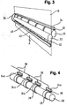
- the main part of the conveying unit 18 as shown in Fig. 1 are individually exemplified in Fig. 2 .
- the absorbent web to be dispensed passes through the nip between a drive roll 20 and a guide roll which, in Fig. 2 , are individually shown without their correct mutual arrangement.
- the drive roll might be fully coated by a high friction covering or by rings 28 of a high friction component, like suitable plastic material or rubber.
- the guide roll can be made of any suitable material which cooperates with the drive roll to achieve a safe transport of the absorbent web between drive roll 20 and guide roll 22.
- Fig. 2 also exemplifies the possible size of a tear bar which might be a part of the conveying unit 18 so that the servicing of the dispenser consisting of individual modules might be simplified.
- the tear bar 24 is also possible to provide the tear bar 24 separately to the conveying unit.
- the tear bar 24 is separately affixed to the housing of the dispenser.
- Tear bar 24 is provided with cutting teeth 30 which can be used by the user to sever a suitable length of the absorbent web.
- the invention is not restricted to this specific type of dispenser and it is also possible to provide tear bars cooperating with the conveying unit in order to automatically sever a metered length of absorbent sheet.
- Fig. 3 schematically shows a first embodiment of the invention.
- the absorbent web 16 is transported in the direction of arrow A. It passes through the nip between drive roll 20 and guide roll 22.
- the absorbent web 16 is shown in Fig. 3 as if it were translucent.
- a brush 32 is provided with bristles or filaments which sweep over the circumferential surface of drive roll 20. Such brush is provided with conductive bristles or filaments in order to collect excess electrons corresponding to negative charges from the surface of the drive roll 20.
- the filaments of the brushes have a length between about 10mm and 25mm. This makes it possible to compensate for small positional deviations from the optimum position of the brush 34 and also makes it possible that the bristles or filaments 36 can bend and sweep over the surface of the drive roll 20 in order to increase the contact time between individual positions of the drive roll and the fibers of the brush. The longer the contact between the brush and an individual position on the surface of the drive roll is, the better are the chances that an electron can migrate from the drive roll 20 into the fibers 36 of the brush 37.
- the charge collected by the brush 34 is directed to a conducive wire 38 from which it is directed to a second brush 40 which is also provided with fibers 42 (bristles or filaments).
- the second brush 40 is positioned such as to contact the absorbent web 16 at the position 32 in which the absorbent web is positively charged corresponding to a lack of electrons.
- the second brush 40 and especially its fibers 42 serve to contact the absorbent web 16 and to neutralise the positive static charge of the absorbent web by supplying a negative charge to the paper web.
- the attachment of the first and second brush at a fixed position relative to the housing of the dispenser needs not to be specified here because this can be easily realized by a skilled person.
- This easy assembly of the two brushes 34 and 40 as well as the conductive wire 38 inbetween makes it possible to easily modify an existing dispenser in which a high build-up of undesired electrostatic load could be observed.
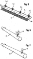
- Fig. 4 exemplifies another embodiment of the invention in which there is not one single first brush 34 as shown in Fig. 3 .
- brush 34 extends over the whole effective length of drive roll 20.
- drive roll 20 can be provided with specific rings 28 of high friction material which serve to contact the absorbent web in cooperation with the guide roll 22. In such a cause, the electrostatic load will also build-up in such specific regions 28 of the drive roll 20. Therefore, it is also possible to provide individual, separate brushes 34a to 34d, each of which is provide with a conductive wire collecting the negative charges and transporting it, as shown in Fig. 3 to a suitable means for either neutralising or consuming it.
- the fibers of the brushes can be made of a material which is specifically adapted to the component of the dispenser which is in contact to such bristles or filaments. It is easily possible that different materials are best suited for e.g. touching a drive roll 20 or an absorbent web 16. Suitable materials for the fibers (bristles or filaments) of the brushes are carbon fibers, nylon fibers, natural hair, stainless steel, SUS304 material, acrylic fibers coated with copper or synthetic conductive fibers.
- Fig. 3 and Fig. 4 always exemplify the collection of negative charges at a drive roll.
- a tear bar it might not be necessary to arrange a brush because tear bars can be made of a conductive material so that the electron transport is considerably quicker so that it might be sufficient simply to attach a conductive wire to a tear bar.
- Fig. 5 shows a tear bar 24 with cutting teeth 30 which is provided with a plurality of first brushes 34a, 34b, 34c and 34d which are attached to the tear bar.
- first brushes 34a, 34b, 34c and 34d which are attached to the tear bar.
- second brush 40 also attached to the tear bar.
- the tear bar has a multiple function.
- the first brushes 34a, to 34d sweep the guide roll to connect excess static loads.
- the second brush 40 sweeps over the paper front in order to reintroduce the excess load into the positively charged paper.
- Figs. 6 and 7 show further embodiments of the invention in which the undesirable build-up of static load is not neutralised but consumed. It should be understood that the further embodiments as described in the following can also be used in addition to the embodiments as described above.
- the principle is used that an LED is a low energy consuming light source that can be lightened by the small amount energy that the static electricity generates. If the electrostatically charged part is connected by an electrical wire or in connection with the charged parts, the LED 44 as schematically shown on Fig. 6 in contact to a drive roll 20 could be used to dissipate the charges.
- Fig. 6 is highly simplified. When realizing the solution according to Fig. 6 , it is also advisable to use a brush in order to collect the excess charge from drive roll 20 or any other suitable part of the dispenser and to connect all such brushes via a wiring to the LED in order to energize the LED.
- Fig. 7 shows an alternative solution to that as shown in Fig. 6 using an LED.
- another electronic part is used which does not dissipate but store the energy.
- a capacitance 46 collects the excess charges and stores it.
- the capacitor 26 allows the electrostatic charges to be stored until the power could used somewhere else in the dispenser, e.g. by using again an LED which could indicate to surface personnel that a high electrostatic load was build-up in a specific dispenser.
- Fig. 7 is highly simplified.
- the excess negative charge at the part of the dispenser here exemplified as a guide roll 22 has to be collected e.g. by means of one or several brushes and guided by a low resistance wiring to another part of the dispenser where the charge is directed to the capacitance 46 and stored there.
- the embodiment as described above have in common that the electrical charges building-up in a dispenser are either neutralised or consumed or both neutralised and consumed so as to stay below a critical value which should be avoided in order to damage other electronic components of the dispenser or even expose a user to the discharge of an electrostatic load.
Claims (11)
- Appareil pour distribuer des produits absorbants en feuilles (16) comprenant :- un magasin (14) avec une bande absorbante (16) à distribuer ;- un moyen de convoyage (18) avec au moins un élément de convoyage (20, 22) pour faire avancer la bande absorbante (16) ; et- un moyen (24) pour trancher la bande (16) afin de former des produits absorbants en feuilles ;- un moyen (34 ; 34a, 34b, 34c, 34d) pour collecter les charges électriques causées par l'électricité statique comprenant au moins un élément formant balai ; et- un moyen (40 ; 44 ; 46) pour neutraliser et/ou consommer les charges électriques ;caractérisé en ce que l'appareil comprend en outre- un moyen (38) pour diriger, au moyen d'une connexion électriquement conductrice, les charges électriques vers un autre élément dans l'appareil (10) de distribution ; dans lequel- le moyen (40 ; 44 ; 46) pour neutraliser les charges électriques est en contact avec un élément chargé positivement (16) à l'intérieur du distributeur ; et- comprend au moins un deuxième balai (40) qui est en contact avec l'élément chargé positivement (16).
- Appareil de distribution selon la revendication 1, caractérisé en ce que le moyen (34) pour collecter des charges électriques est attaché au moyen (24) pour trancher la bande, de préférence une barre de déchirage.
- Appareil de distribution selon la revendication 1 ou 2, caractérisé en ce que ledit au moins un élément formant balai (34 ; 34a, 34b, 34c, 34d) touche un élément de convoyage (20) de l'appareil de distribution, de préférence un rouleau (20) en contact avec la bande absorbante (16).
- Appareil de distribution selon la revendication 3, caractérisé en ce que ledit au moins un élément formant balai (34) s'étend le long de la majeure partie de la longueur de l'élément de convoyage (20), ledit au moins un élément formant balai étant de préférence un balai unique (34).
- Appareil de distribution selon la revendication 3, caractérisé en ce que plusieurs balais distincts (34 ; 34a, 34b, 34c, 34d) sont placés en différentes positions (38) de l'élément de convoyage (20) où la bande absorbante (16) entre en contact avec l'élément de convoyage (20).
- Appareil de distribution selon l'une quelconque des revendications précédentes, caractérisé en ce que le moyen pour consommer les charges électriques est un composant électrique ou électronique (44, 46), de préférence une diode électroluminescente (44).
- Appareil de distribution selon l'une quelconque des revendications 4 ou 5, caractérisé en ce que ledit au moins un premier élément formant balai (34 ; 34a, 34b, 34c, 34d) et/ou le deuxième élément formant balai (40) comprend des fibres constituées principalement de n'importe lequel des matériaux du groupe comprenant les fibres de carbone, les fibres de nylon, les cheveux naturels, l'acier inoxydable, le matériau SUS304, les fibres d'acrylique revêtues d'un matériau conducteur comme le cuivre ou les fibres conductrices synthétiques.
- Appareil de distribution selon la revendication 1 ou 7, caractérisé en ce que l'élément chargé positivement est la bande absorbante (16).
- Procédé pour modifier un appareil de distribution de produits absorbants en feuilles comprenant :- un magasin (14) avec une bande absorbante (16) à distribuer ;- un moyen de convoyage (18) avec au moins un élément de convoyage (20, 22) pour faire avancer la bande absorbante (16) ; et- un moyen (24) pour trancher la bande (16) afin de former des produits absorbants en feuilles ;le procédé comprenant l'étape suivante :- placer un moyen (34 ; 34a, 34b, 34c, 34d) pour collecter les charges électriques causées par l'électricité statique en contact avec un premier élément (24) à l'intérieur de l'appareil avec une charge électrostatique négative ;et étant caractérisé par les étapes suivantes :- placer un moyen (40 ; 44 ; 46) pour neutraliser les charges électriques en contact avec un deuxième élément (16) à l'intérieur de l'appareil avec une charge électrostatique positive ; et- établir une connexion électriquement conductrice entre le premier élément (24) et le deuxième élément (16).
- Procédé pour modifier un appareil de distribution de produits absorbants en feuilles comprenant :- un magasin (14) avec une bande absorbante (16) à distribuer ;- un moyen de convoyage (18) avec au moins un élément de convoyage (20, 22) pour faire avancer la bande absorbante (16) ; et- un moyen (24) pour trancher la bande (16) afin de former des produits absorbants en feuilles ;le procédé comprenant l'étape suivante :- placer un moyen (34 ; 34a, 34b, 34c, 34d) pour collecter les charges électriques causées par l'électricité statique en contact avec un premier élément (24) à l'intérieur de l'appareil avec une charge électrostatique négative ;et étant caractérisé par l'étape suivante :- placer un moyen pour consommer les charges électriques en contact électrique avec le premier élément (24), le moyen pour consommer les charges électriques étant une diode électroluminescente (44).
- Procédé pour modifier un appareil selon la revendication 9 ou 10, caractérisé en ce que le moyen pour collecter les charges électriques comprend au moins un élément formant balai (34 ; 34a, 34b, 34c, 34d) en contact avec un élément de convoyage (20) de l'appareil de distribution.
Applications Claiming Priority (1)
| Application Number | Priority Date | Filing Date | Title |
|---|---|---|---|
| PCT/EP2010/059712 WO2012003865A1 (fr) | 2010-07-07 | 2010-07-07 | Appareil de distribution de produits en feuille absorbants et procédé de modification d'un tel appareil |
Publications (2)
| Publication Number | Publication Date |
|---|---|
| EP2592984A1 EP2592984A1 (fr) | 2013-05-22 |
| EP2592984B1 true EP2592984B1 (fr) | 2016-05-04 |
Family
ID=43757858
Family Applications (1)
| Application Number | Title | Priority Date | Filing Date |
|---|---|---|---|
| EP10737810.1A Not-in-force EP2592984B1 (fr) | 2010-07-07 | 2010-07-07 | Appareil de distribution de produits en feuille absorbants et procédé de modification d'un tel appareil |
Country Status (11)
| Country | Link |
|---|---|
| US (2) | US9908728B2 (fr) |
| EP (1) | EP2592984B1 (fr) |
| CN (1) | CN102970910A (fr) |
| AU (1) | AU2010357053A1 (fr) |
| BR (1) | BR112013000347A2 (fr) |
| CA (1) | CA2804365A1 (fr) |
| MX (1) | MX2012015005A (fr) |
| RU (1) | RU2530861C2 (fr) |
| UA (1) | UA106304C2 (fr) |
| WO (1) | WO2012003865A1 (fr) |
| ZA (1) | ZA201209347B (fr) |
Families Citing this family (5)
| Publication number | Priority date | Publication date | Assignee | Title |
|---|---|---|---|---|
| WO2012003865A1 (fr) * | 2010-07-07 | 2012-01-12 | Sca Hygiene Products Ab | Appareil de distribution de produits en feuille absorbants et procédé de modification d'un tel appareil |
| US20120113559A1 (en) * | 2010-11-09 | 2012-05-10 | Applied Materials, Inc. | Electrostatic discharge prevention for large area substrate processing system |
| WO2012088521A2 (fr) | 2010-12-23 | 2012-06-28 | Pregis Innovative Packaging, Inc. | Distribution de système de fardage alimenté par le centre et dispositif de coupe |
| US11007746B2 (en) | 2017-05-11 | 2021-05-18 | Pregis Innovative Packaging Llc | Dunnage supply intake |
| US11034121B2 (en) | 2017-05-11 | 2021-06-15 | Pregis Innovative Packaging Llc | Dunnage apparatus carton filler |
Citations (5)
| Publication number | Priority date | Publication date | Assignee | Title |
|---|---|---|---|---|
| US4860159A (en) * | 1988-09-12 | 1989-08-22 | The Simco Company, Inc. | Tape dispenser with static neutralizer |
| JP2003100496A (ja) * | 2001-09-20 | 2003-04-04 | Asahi Denki Kasei Kk | 静電検知器 |
| KR20050004329A (ko) * | 2003-07-02 | 2005-01-12 | 에스케이텔레텍주식회사 | 정전기 방지를 위한 이동통신 단말기 |
| US20080099595A1 (en) * | 2006-10-30 | 2008-05-01 | Kimberly-Clark Worldwide, Inc. | System and method for dissipating static electricity in an electronic sheet material dispenser |
| US20080192403A1 (en) * | 2007-02-09 | 2008-08-14 | Pin Kuang Chen | Static electricity neutralizer |
Family Cites Families (75)
| Publication number | Priority date | Publication date | Assignee | Title |
|---|---|---|---|---|
| US1120984A (en) * | 1912-02-09 | 1914-12-15 | John S Thompson | Static collecting and discharging mechanism. |
| US1396318A (en) * | 1920-07-15 | 1921-11-08 | Bunger August | Antistatic friction device |
| US2839345A (en) * | 1952-01-23 | 1958-06-17 | Bay West Paper Company | Cabinet mechanism for dispensing prededtermined lengths of a web such as towelling |
| US2879396A (en) * | 1957-05-03 | 1959-03-24 | Plastics-treating apparatus | |
| US2945434A (en) * | 1959-07-02 | 1960-07-19 | Haloid Xerox Inc | Sheet feed mechanism |
| US3396917A (en) * | 1966-03-01 | 1968-08-13 | Du Pont | Method for unwinding rolls |
| DE1814222B1 (de) * | 1968-12-12 | 1970-07-30 | Kodak Ag | Selbsttaetige Filmeinfaedelvorrichtung |
| US3542578A (en) * | 1969-05-07 | 1970-11-24 | Frank C Lang | Method of preventing static charges in printing |
| US3670203A (en) * | 1970-04-20 | 1972-06-13 | Eastman Kodak Co | Method of and apparatus for imparting an electrical charge to a web of film or paper or the like |
| US3636408A (en) * | 1970-05-26 | 1972-01-18 | Technical Tape Corp | Tape dispenser with static electricity neutralizer |
| US3757164A (en) * | 1970-07-17 | 1973-09-04 | Minnesota Mining & Mfg | Neutralizing device |
| DE2146539C3 (de) * | 1971-09-17 | 1979-10-11 | Hoechst Ag, 6000 Frankfurt | Vorrichtung zum homogenen Auf· oder Entladen der Oberfläche von elektrofotografischen Aufzeichnungsmaterialien |
| JPS4898132A (fr) * | 1972-03-25 | 1973-12-13 | ||
| US3904929A (en) * | 1972-11-10 | 1975-09-09 | Kohkoku Chemical Ind Co | Electro-discharging sheet, and an electro-discharging apparatus provided with an electro-discharging electrode composed of the said sheet, and a process for electro-discharging with the said apparatus |
| US3981459A (en) * | 1975-04-24 | 1976-09-21 | Xerox Corporation | Photoelectrophoretic electrostatic tacking capstan web tension system |
| JPS5583199A (en) * | 1978-12-20 | 1980-06-23 | Olympus Optical Co | Static eliminator |
| US4352143A (en) * | 1980-05-27 | 1982-09-28 | Kenkichi Uno | Device for discharging static electricity and method of producing the same |
| US4363070A (en) * | 1980-09-02 | 1982-12-07 | Polaroid Corporation | Neutralization of electrostatic charges |
| SU1061101A1 (ru) * | 1980-12-10 | 1983-12-15 | Особое конструкторское бюро Института высоких температур АН СССР | Устройство дл удалени электростатических зар дов с поверхности бумажного полотна роторной машины |
| US4494166A (en) * | 1982-09-21 | 1985-01-15 | Xerox Corporation | Printing machine with static elimination system |
| JPS5992873A (ja) * | 1982-11-20 | 1984-05-29 | Teijin Seiki Co Ltd | 巻取機械からのパツケ−ジ玉揚げ方法および装置 |
| SU1228308A1 (ru) * | 1984-04-03 | 1986-04-30 | Московский Ордена Трудового Красного Знамени Полиграфический Институт | Нейтрализатор зар дов статического электричества |
| US4696562A (en) * | 1984-06-18 | 1987-09-29 | Matsushita Electric Industrial Co., Ltd. | Multifunctional copying machine |
| FR2584560B1 (fr) * | 1985-07-03 | 1990-05-11 | Telephonie Ind Commerciale | Dispositif effaceur de charges electrostatiques |
| GB2190329B (en) * | 1986-05-13 | 1990-06-27 | Xerox Corp | Image fusing apparatus |
| US4737809A (en) * | 1986-11-24 | 1988-04-12 | Canon Kabushiki Kaisha | Static electricity eliminating mechanism for camera |
| US4960248A (en) * | 1989-03-16 | 1990-10-02 | Bauer Industries, Inc. | Apparatus and method for dispensing toweling |
| US5377069A (en) * | 1989-04-07 | 1994-12-27 | Andreasson; Tomas | Oscillating circuit for the elimination/reduction of static electricity |
| US5041941A (en) * | 1989-12-06 | 1991-08-20 | Westvaco Corporation | Charge control for EB coated paperboard |
| US5228373A (en) * | 1990-01-08 | 1993-07-20 | Robert A. Foisie | Method and apparatus using electrostatic charges to temporarily hold packets of paper |
| US5354607A (en) * | 1990-04-16 | 1994-10-11 | Xerox Corporation | Fibrillated pultruded electronic components and static eliminator devices |
| KR920008465B1 (ko) * | 1990-06-18 | 1992-09-30 | 주식회사 금성사 | 전자 사진 방식 기기에서의 감광체 드럼 전원 공급 방법 |
| WO1992012612A1 (fr) * | 1990-12-26 | 1992-07-23 | Eastman Kodak Company | Systeme de decharge du bord d'avance d'une bande photographique |
| US5121285A (en) * | 1991-02-11 | 1992-06-09 | Eastman Kodak Company | Method and apparatus for eliminating residual charge on plastic sheets having an image formed thereon by a photocopier |
| KR100237428B1 (ko) * | 1991-12-20 | 2000-01-15 | 김영환 | 정전기 제거용 브러쉬 |
| US5302037A (en) * | 1992-04-10 | 1994-04-12 | Hecon Corporation | Web handling and feeding system for printers |
| US5375785A (en) * | 1992-12-02 | 1994-12-27 | Georgia-Pacific Corporation | Automatic web transfer mechanism for flexible sheet dispenser |
| US5452832A (en) * | 1993-04-06 | 1995-09-26 | Qts S.R.L. | Automatic dispenser for paper towels severable from a continuous roll |
| JP2801501B2 (ja) * | 1993-08-06 | 1998-09-21 | シャープ株式会社 | 用紙後処理装置 |
| JP3078688B2 (ja) * | 1993-10-15 | 2000-08-21 | 富士写真フイルム株式会社 | 感光材料の切断装置 |
| JP3590449B2 (ja) * | 1995-05-22 | 2004-11-17 | ペンタックス株式会社 | 電子現像型カメラ |
| US6069354A (en) * | 1995-11-30 | 2000-05-30 | Alfano; Robert R. | Photonic paper product dispenser |
| EP0828186B1 (fr) * | 1996-09-04 | 2003-11-26 | Fuji Photo Film Co., Ltd. | Méthode et dispositif de production de film photographique en rouleau |
| US5996925A (en) * | 1997-03-03 | 1999-12-07 | Toray Engineering Co., Ltd. | Method and apparatus for detecting yarn tension and method for winding yarn |
| JPH1129237A (ja) * | 1997-07-09 | 1999-02-02 | Brother Ind Ltd | シート体排出装置 |
| US6314850B1 (en) * | 1998-01-22 | 2001-11-13 | Perrin Manufacturing Company | Paper toweling dispensing system |
| US6252757B1 (en) * | 1999-07-23 | 2001-06-26 | Ultrafab, Inc. | Static brushes and methods of fabricating same |
| US6604876B2 (en) * | 2000-09-29 | 2003-08-12 | Zih Corp. | System for dissipating electrostatic charge in a printer |
| JP2002196638A (ja) * | 2000-12-27 | 2002-07-12 | Brother Ind Ltd | 画像形成装置およびプロセス装置 |
| US7017856B2 (en) * | 2001-02-09 | 2006-03-28 | Georgia-Pacific Corporation | Static build-up control in dispensing system |
| US6592067B2 (en) * | 2001-02-09 | 2003-07-15 | Georgia-Pacific Corporation | Minimizing paper waste carousel-style dispenser apparatus, sensor, method and system with proximity sensor |
| JP2002313057A (ja) * | 2001-04-18 | 2002-10-25 | Fuji Photo Film Co Ltd | 磁気テープカセット |
| US6498913B1 (en) * | 2001-08-27 | 2002-12-24 | Xerox Corporation | Static charge controlling system and a reproduction machine having same |
| US6952555B2 (en) * | 2001-12-13 | 2005-10-04 | Illinois Tool Works Inc. | Low profile passive static control device |
| US7341170B2 (en) * | 2002-03-07 | 2008-03-11 | Georgia-Pacific Consumer Operations Llc | Apparatus and methods usable in connection with dispensing flexible sheet material from a roll |
| US6920030B2 (en) * | 2002-08-08 | 2005-07-19 | Honeywell International Inc. | Apparatus for eliminating static electrical charges from a web of dielectric sheet material |
| US7168653B2 (en) * | 2003-01-09 | 2007-01-30 | The Colman Group, Inc. | Low cost roll dispenser |
| US7040566B1 (en) * | 2003-04-08 | 2006-05-09 | Alwin Manufacturing Co., Inc. | Dispenser with material-recognition apparatus and material-recognition method |
| JP4295663B2 (ja) * | 2004-05-12 | 2009-07-15 | 株式会社リコー | 画像形成装置 |
| US7398944B2 (en) * | 2004-12-01 | 2008-07-15 | Kimberly-Clark Worldwide, Inc. | Hands-free electronic towel dispenser |
| CA2591552C (fr) * | 2004-12-17 | 2012-03-06 | Ultrafab, Inc. | Appareil et procede de fabrication d'articles constitues d'une matiere filamenteuse |
| US7837077B2 (en) * | 2006-03-28 | 2010-11-23 | Sca Tissue North America, Llc | Hands-free powered absorbent sheet dispenser |
| US7708271B2 (en) * | 2006-08-03 | 2010-05-04 | Xerox Corporation | Non-contacting static brush for a sheet stacker |
| ITTV20060195A1 (it) | 2006-10-31 | 2008-05-01 | Nice Spa | Attuatore rotativo. |
| WO2008125127A1 (fr) * | 2007-04-11 | 2008-10-23 | Firma Ssm Schärer Schweiter Mettler Ag | Unité d'enroulement pour machine de traitement des filés |
| US8028942B2 (en) * | 2008-08-01 | 2011-10-04 | Fellowes, Inc. | Bin full detection with light intensity sensing |
| US9986874B2 (en) * | 2008-12-02 | 2018-06-05 | Sca Tissue North American Llc | Absorbent sheet dispenser having improved hand sensor performance |
| GB0920357D0 (en) * | 2009-11-20 | 2010-01-06 | Systems Ltd Q | Pill holder |
| WO2012003865A1 (fr) * | 2010-07-07 | 2012-01-12 | Sca Hygiene Products Ab | Appareil de distribution de produits en feuille absorbants et procédé de modification d'un tel appareil |
| US8320817B2 (en) * | 2010-08-18 | 2012-11-27 | Eastman Kodak Company | Charge removal from a sheet |
| US20120099911A1 (en) * | 2010-10-21 | 2012-04-26 | Mark Cameron Zaretsky | Concurrently removing sheet charge and curl |
| US8730643B2 (en) * | 2010-10-22 | 2014-05-20 | Sca Hygiene Products Ab | Apparatus with arc generator for dispensing absorbent sheet products |
| JP6067994B2 (ja) * | 2012-04-16 | 2017-01-25 | シャープ株式会社 | 画像形成装置 |
| JP6056667B2 (ja) * | 2013-06-07 | 2017-01-11 | 富士ゼロックス株式会社 | 露光装置、画像形成装置 |
| US9187284B2 (en) * | 2013-08-22 | 2015-11-17 | Canon Kabushiki Kaisha | Sheet discharge device and image forming apparatus |
-
2010
- 2010-07-07 WO PCT/EP2010/059712 patent/WO2012003865A1/fr active Application Filing
- 2010-07-07 BR BR112013000347A patent/BR112013000347A2/pt not_active IP Right Cessation
- 2010-07-07 MX MX2012015005A patent/MX2012015005A/es unknown
- 2010-07-07 RU RU2013104984/12A patent/RU2530861C2/ru not_active IP Right Cessation
- 2010-07-07 AU AU2010357053A patent/AU2010357053A1/en not_active Abandoned
- 2010-07-07 UA UAA201301429A patent/UA106304C2/ru unknown
- 2010-07-07 US US13/808,262 patent/US9908728B2/en not_active Expired - Fee Related
- 2010-07-07 EP EP10737810.1A patent/EP2592984B1/fr not_active Not-in-force
- 2010-07-07 CN CN2010800679243A patent/CN102970910A/zh active Pending
- 2010-07-07 CA CA2804365A patent/CA2804365A1/fr not_active Abandoned
-
2012
- 2012-12-10 ZA ZA2012/09347A patent/ZA201209347B/en unknown
-
2017
- 2017-12-11 US US15/837,428 patent/US10118783B2/en not_active Expired - Fee Related
Patent Citations (5)
| Publication number | Priority date | Publication date | Assignee | Title |
|---|---|---|---|---|
| US4860159A (en) * | 1988-09-12 | 1989-08-22 | The Simco Company, Inc. | Tape dispenser with static neutralizer |
| JP2003100496A (ja) * | 2001-09-20 | 2003-04-04 | Asahi Denki Kasei Kk | 静電検知器 |
| KR20050004329A (ko) * | 2003-07-02 | 2005-01-12 | 에스케이텔레텍주식회사 | 정전기 방지를 위한 이동통신 단말기 |
| US20080099595A1 (en) * | 2006-10-30 | 2008-05-01 | Kimberly-Clark Worldwide, Inc. | System and method for dissipating static electricity in an electronic sheet material dispenser |
| US20080192403A1 (en) * | 2007-02-09 | 2008-08-14 | Pin Kuang Chen | Static electricity neutralizer |
Also Published As
| Publication number | Publication date |
|---|---|
| US20180099830A1 (en) | 2018-04-12 |
| CA2804365A1 (fr) | 2012-01-12 |
| RU2013104984A (ru) | 2014-08-20 |
| ZA201209347B (en) | 2013-09-25 |
| EP2592984A1 (fr) | 2013-05-22 |
| BR112013000347A2 (pt) | 2016-05-31 |
| US20130105613A1 (en) | 2013-05-02 |
| CN102970910A (zh) | 2013-03-13 |
| MX2012015005A (es) | 2013-01-29 |
| US10118783B2 (en) | 2018-11-06 |
| AU2010357053A1 (en) | 2013-01-24 |
| RU2530861C2 (ru) | 2014-10-20 |
| US9908728B2 (en) | 2018-03-06 |
| WO2012003865A1 (fr) | 2012-01-12 |
| UA106304C2 (ru) | 2014-08-11 |
Similar Documents
| Publication | Publication Date | Title |
|---|---|---|
| US10118783B2 (en) | Apparatus for dispensing absorbent sheet products and method for modifying such apparatus | |
| US20200187727A1 (en) | Electronic Dispenser for Flexible Rolled Sheet Material | |
| US8511598B2 (en) | System for dispensing paper rolls with conductive tubes | |
| EP1230886B1 (fr) | Distributeur d'essuie-mains de type carrousel | |
| US4860159A (en) | Tape dispenser with static neutralizer | |
| US6895848B1 (en) | Device for removing one or more lengths of paper from a rolled-up paper strip | |
| US20080100982A1 (en) | System and method for dissipating static electricity in an electronic sheet material dispenser | |
| EP1231823B2 (fr) | Distributeur avec mise à la terre et son procédé | |
| WO2012003867A1 (fr) | Appareil de distribution de produits en feuille absorbants | |
| AU2011317767B2 (en) | Apparatus with arc generator for dispensing absorbent sheet products | |
| US11590672B2 (en) | Sheet punching apparatus | |
| RU2575695C2 (ru) | Устройство с дуговым генератором для раздачи впитывающих листовых изделий | |
| JPH10201697A (ja) | ロ−ル式除塵クリ−ナ |
Legal Events
| Date | Code | Title | Description |
|---|---|---|---|
| PUAI | Public reference made under article 153(3) epc to a published international application that has entered the european phase |
Free format text: ORIGINAL CODE: 0009012 |
|
| 17P | Request for examination filed |
Effective date: 20121203 |
|
| AK | Designated contracting states |
Kind code of ref document: A1 Designated state(s): AL AT BE BG CH CY CZ DE DK EE ES FI FR GB GR HR HU IE IS IT LI LT LU LV MC MK MT NL NO PL PT RO SE SI SK SM TR |
|
| DAX | Request for extension of the european patent (deleted) | ||
| 17Q | First examination report despatched |
Effective date: 20140917 |
|
| GRAP | Despatch of communication of intention to grant a patent |
Free format text: ORIGINAL CODE: EPIDOSNIGR1 |
|
| INTG | Intention to grant announced |
Effective date: 20151015 |
|
| GRAS | Grant fee paid |
Free format text: ORIGINAL CODE: EPIDOSNIGR3 |
|
| GRAJ | Information related to disapproval of communication of intention to grant by the applicant or resumption of examination proceedings by the epo deleted |
Free format text: ORIGINAL CODE: EPIDOSDIGR1 |
|
| GRAR | Information related to intention to grant a patent recorded |
Free format text: ORIGINAL CODE: EPIDOSNIGR71 |
|
| GRAA | (expected) grant |
Free format text: ORIGINAL CODE: 0009210 |
|
| INTG | Intention to grant announced |
Effective date: 20160324 |
|
| AK | Designated contracting states |
Kind code of ref document: B1 Designated state(s): AL AT BE BG CH CY CZ DE DK EE ES FI FR GB GR HR HU IE IS IT LI LT LU LV MC MK MT NL NO PL PT RO SE SI SK SM TR |
|
| REG | Reference to a national code |
Ref country code: GB Ref legal event code: FG4D |
|
| REG | Reference to a national code |
Ref country code: CH Ref legal event code: EP |
|
| REG | Reference to a national code |
Ref country code: AT Ref legal event code: REF Ref document number: 796110 Country of ref document: AT Kind code of ref document: T Effective date: 20160515 |
|
| REG | Reference to a national code |
Ref country code: IE Ref legal event code: FG4D |
|
| REG | Reference to a national code |
Ref country code: DE Ref legal event code: R096 Ref document number: 602010033055 Country of ref document: DE |
|
| REG | Reference to a national code |
Ref country code: FR Ref legal event code: PLFP Year of fee payment: 7 |
|
| REG | Reference to a national code |
Ref country code: SE Ref legal event code: TRGR |
|
| REG | Reference to a national code |
Ref country code: NL Ref legal event code: MP Effective date: 20160504 |
|
| REG | Reference to a national code |
Ref country code: LT Ref legal event code: MG4D |
|
| PG25 | Lapsed in a contracting state [announced via postgrant information from national office to epo] |
Ref country code: NL Free format text: LAPSE BECAUSE OF FAILURE TO SUBMIT A TRANSLATION OF THE DESCRIPTION OR TO PAY THE FEE WITHIN THE PRESCRIBED TIME-LIMIT Effective date: 20160504 Ref country code: NO Free format text: LAPSE BECAUSE OF FAILURE TO SUBMIT A TRANSLATION OF THE DESCRIPTION OR TO PAY THE FEE WITHIN THE PRESCRIBED TIME-LIMIT Effective date: 20160804 Ref country code: LT Free format text: LAPSE BECAUSE OF FAILURE TO SUBMIT A TRANSLATION OF THE DESCRIPTION OR TO PAY THE FEE WITHIN THE PRESCRIBED TIME-LIMIT Effective date: 20160504 |
|
| PGFP | Annual fee paid to national office [announced via postgrant information from national office to epo] |
Ref country code: FI Payment date: 20160822 Year of fee payment: 7 |
|
| REG | Reference to a national code |
Ref country code: AT Ref legal event code: MK05 Ref document number: 796110 Country of ref document: AT Kind code of ref document: T Effective date: 20160504 |
|
| PG25 | Lapsed in a contracting state [announced via postgrant information from national office to epo] |
Ref country code: HR Free format text: LAPSE BECAUSE OF FAILURE TO SUBMIT A TRANSLATION OF THE DESCRIPTION OR TO PAY THE FEE WITHIN THE PRESCRIBED TIME-LIMIT Effective date: 20160504 Ref country code: PT Free format text: LAPSE BECAUSE OF FAILURE TO SUBMIT A TRANSLATION OF THE DESCRIPTION OR TO PAY THE FEE WITHIN THE PRESCRIBED TIME-LIMIT Effective date: 20160905 Ref country code: GR Free format text: LAPSE BECAUSE OF FAILURE TO SUBMIT A TRANSLATION OF THE DESCRIPTION OR TO PAY THE FEE WITHIN THE PRESCRIBED TIME-LIMIT Effective date: 20160805 Ref country code: ES Free format text: LAPSE BECAUSE OF FAILURE TO SUBMIT A TRANSLATION OF THE DESCRIPTION OR TO PAY THE FEE WITHIN THE PRESCRIBED TIME-LIMIT Effective date: 20160504 Ref country code: LV Free format text: LAPSE BECAUSE OF FAILURE TO SUBMIT A TRANSLATION OF THE DESCRIPTION OR TO PAY THE FEE WITHIN THE PRESCRIBED TIME-LIMIT Effective date: 20160504 |
|
| PGFP | Annual fee paid to national office [announced via postgrant information from national office to epo] |
Ref country code: SE Payment date: 20160718 Year of fee payment: 7 |
|
| PG25 | Lapsed in a contracting state [announced via postgrant information from national office to epo] |
Ref country code: IT Free format text: LAPSE BECAUSE OF FAILURE TO SUBMIT A TRANSLATION OF THE DESCRIPTION OR TO PAY THE FEE WITHIN THE PRESCRIBED TIME-LIMIT Effective date: 20160504 Ref country code: BE Free format text: LAPSE BECAUSE OF NON-PAYMENT OF DUE FEES Effective date: 20160731 |
|
| PG25 | Lapsed in a contracting state [announced via postgrant information from national office to epo] |
Ref country code: EE Free format text: LAPSE BECAUSE OF FAILURE TO SUBMIT A TRANSLATION OF THE DESCRIPTION OR TO PAY THE FEE WITHIN THE PRESCRIBED TIME-LIMIT Effective date: 20160504 Ref country code: DK Free format text: LAPSE BECAUSE OF FAILURE TO SUBMIT A TRANSLATION OF THE DESCRIPTION OR TO PAY THE FEE WITHIN THE PRESCRIBED TIME-LIMIT Effective date: 20160504 Ref country code: SK Free format text: LAPSE BECAUSE OF FAILURE TO SUBMIT A TRANSLATION OF THE DESCRIPTION OR TO PAY THE FEE WITHIN THE PRESCRIBED TIME-LIMIT Effective date: 20160504 Ref country code: RO Free format text: LAPSE BECAUSE OF FAILURE TO SUBMIT A TRANSLATION OF THE DESCRIPTION OR TO PAY THE FEE WITHIN THE PRESCRIBED TIME-LIMIT Effective date: 20160504 Ref country code: CZ Free format text: LAPSE BECAUSE OF FAILURE TO SUBMIT A TRANSLATION OF THE DESCRIPTION OR TO PAY THE FEE WITHIN THE PRESCRIBED TIME-LIMIT Effective date: 20160504 |
|
| REG | Reference to a national code |
Ref country code: DE Ref legal event code: R097 Ref document number: 602010033055 Country of ref document: DE |
|
| PG25 | Lapsed in a contracting state [announced via postgrant information from national office to epo] |
Ref country code: SM Free format text: LAPSE BECAUSE OF FAILURE TO SUBMIT A TRANSLATION OF THE DESCRIPTION OR TO PAY THE FEE WITHIN THE PRESCRIBED TIME-LIMIT Effective date: 20160504 Ref country code: AT Free format text: LAPSE BECAUSE OF FAILURE TO SUBMIT A TRANSLATION OF THE DESCRIPTION OR TO PAY THE FEE WITHIN THE PRESCRIBED TIME-LIMIT Effective date: 20160504 Ref country code: BE Free format text: LAPSE BECAUSE OF FAILURE TO SUBMIT A TRANSLATION OF THE DESCRIPTION OR TO PAY THE FEE WITHIN THE PRESCRIBED TIME-LIMIT Effective date: 20160504 Ref country code: PL Free format text: LAPSE BECAUSE OF FAILURE TO SUBMIT A TRANSLATION OF THE DESCRIPTION OR TO PAY THE FEE WITHIN THE PRESCRIBED TIME-LIMIT Effective date: 20160504 |
|
| REG | Reference to a national code |
Ref country code: CH Ref legal event code: PL |
|
| PLBE | No opposition filed within time limit |
Free format text: ORIGINAL CODE: 0009261 |
|
| STAA | Information on the status of an ep patent application or granted ep patent |
Free format text: STATUS: NO OPPOSITION FILED WITHIN TIME LIMIT |
|
| PG25 | Lapsed in a contracting state [announced via postgrant information from national office to epo] |
Ref country code: MC Free format text: LAPSE BECAUSE OF FAILURE TO SUBMIT A TRANSLATION OF THE DESCRIPTION OR TO PAY THE FEE WITHIN THE PRESCRIBED TIME-LIMIT Effective date: 20160504 |
|
| 26N | No opposition filed |
Effective date: 20170207 |
|
| PG25 | Lapsed in a contracting state [announced via postgrant information from national office to epo] |
Ref country code: LI Free format text: LAPSE BECAUSE OF NON-PAYMENT OF DUE FEES Effective date: 20160731 Ref country code: CH Free format text: LAPSE BECAUSE OF NON-PAYMENT OF DUE FEES Effective date: 20160731 |
|
| REG | Reference to a national code |
Ref country code: IE Ref legal event code: MM4A |
|
| PG25 | Lapsed in a contracting state [announced via postgrant information from national office to epo] |
Ref country code: SI Free format text: LAPSE BECAUSE OF FAILURE TO SUBMIT A TRANSLATION OF THE DESCRIPTION OR TO PAY THE FEE WITHIN THE PRESCRIBED TIME-LIMIT Effective date: 20160504 |
|
| REG | Reference to a national code |
Ref country code: FR Ref legal event code: PLFP Year of fee payment: 8 |
|
| PG25 | Lapsed in a contracting state [announced via postgrant information from national office to epo] |
Ref country code: IE Free format text: LAPSE BECAUSE OF NON-PAYMENT OF DUE FEES Effective date: 20160707 |
|
| PG25 | Lapsed in a contracting state [announced via postgrant information from national office to epo] |
Ref country code: LU Free format text: LAPSE BECAUSE OF NON-PAYMENT OF DUE FEES Effective date: 20160707 |
|
| REG | Reference to a national code |
Ref country code: SE Ref legal event code: EUG |
|
| PG25 | Lapsed in a contracting state [announced via postgrant information from national office to epo] |
Ref country code: FI Free format text: LAPSE BECAUSE OF NON-PAYMENT OF DUE FEES Effective date: 20170707 Ref country code: SE Free format text: LAPSE BECAUSE OF NON-PAYMENT OF DUE FEES Effective date: 20170708 |
|
| PG25 | Lapsed in a contracting state [announced via postgrant information from national office to epo] |
Ref country code: HU Free format text: LAPSE BECAUSE OF FAILURE TO SUBMIT A TRANSLATION OF THE DESCRIPTION OR TO PAY THE FEE WITHIN THE PRESCRIBED TIME-LIMIT; INVALID AB INITIO Effective date: 20100707 Ref country code: CY Free format text: LAPSE BECAUSE OF FAILURE TO SUBMIT A TRANSLATION OF THE DESCRIPTION OR TO PAY THE FEE WITHIN THE PRESCRIBED TIME-LIMIT Effective date: 20160504 |
|
| PG25 | Lapsed in a contracting state [announced via postgrant information from national office to epo] |
Ref country code: MK Free format text: LAPSE BECAUSE OF FAILURE TO SUBMIT A TRANSLATION OF THE DESCRIPTION OR TO PAY THE FEE WITHIN THE PRESCRIBED TIME-LIMIT Effective date: 20160504 Ref country code: TR Free format text: LAPSE BECAUSE OF FAILURE TO SUBMIT A TRANSLATION OF THE DESCRIPTION OR TO PAY THE FEE WITHIN THE PRESCRIBED TIME-LIMIT Effective date: 20160504 Ref country code: MT Free format text: LAPSE BECAUSE OF NON-PAYMENT OF DUE FEES Effective date: 20160731 Ref country code: IS Free format text: LAPSE BECAUSE OF FAILURE TO SUBMIT A TRANSLATION OF THE DESCRIPTION OR TO PAY THE FEE WITHIN THE PRESCRIBED TIME-LIMIT Effective date: 20160504 |
|
| REG | Reference to a national code |
Ref country code: FR Ref legal event code: PLFP Year of fee payment: 9 |
|
| PG25 | Lapsed in a contracting state [announced via postgrant information from national office to epo] |
Ref country code: BG Free format text: LAPSE BECAUSE OF FAILURE TO SUBMIT A TRANSLATION OF THE DESCRIPTION OR TO PAY THE FEE WITHIN THE PRESCRIBED TIME-LIMIT Effective date: 20160504 |
|
| PG25 | Lapsed in a contracting state [announced via postgrant information from national office to epo] |
Ref country code: AL Free format text: LAPSE BECAUSE OF FAILURE TO SUBMIT A TRANSLATION OF THE DESCRIPTION OR TO PAY THE FEE WITHIN THE PRESCRIBED TIME-LIMIT Effective date: 20160504 |
|
| REG | Reference to a national code |
Ref country code: DE Ref legal event code: R082 Ref document number: 602010033055 Country of ref document: DE Representative=s name: HOFFMANN - EITLE PATENT- UND RECHTSANWAELTE PA, DE Ref country code: DE Ref legal event code: R081 Ref document number: 602010033055 Country of ref document: DE Owner name: ESSITY HYGIENE AND HEALTH AKTIEBOLAG, SE Free format text: FORMER OWNER: SCA HYGIENE PRODUCTS AB, GOETEBORG/GOTENBURG, SE |
|
| PGFP | Annual fee paid to national office [announced via postgrant information from national office to epo] |
Ref country code: FR Payment date: 20190619 Year of fee payment: 10 |
|
| PGFP | Annual fee paid to national office [announced via postgrant information from national office to epo] |
Ref country code: DE Payment date: 20190625 Year of fee payment: 10 |
|
| PGFP | Annual fee paid to national office [announced via postgrant information from national office to epo] |
Ref country code: GB Payment date: 20190703 Year of fee payment: 10 |
|
| REG | Reference to a national code |
Ref country code: DE Ref legal event code: R119 Ref document number: 602010033055 Country of ref document: DE |
|
| GBPC | Gb: european patent ceased through non-payment of renewal fee |
Effective date: 20200707 |
|
| PG25 | Lapsed in a contracting state [announced via postgrant information from national office to epo] |
Ref country code: GB Free format text: LAPSE BECAUSE OF NON-PAYMENT OF DUE FEES Effective date: 20200707 Ref country code: FR Free format text: LAPSE BECAUSE OF NON-PAYMENT OF DUE FEES Effective date: 20200731 |
|
| PG25 | Lapsed in a contracting state [announced via postgrant information from national office to epo] |
Ref country code: DE Free format text: LAPSE BECAUSE OF NON-PAYMENT OF DUE FEES Effective date: 20210202 |