EP2592261A1 - Verfahren zum Betrieb eines Start-Stopp-Systems eines Kraftfahrzeugs und Kraftfahrzeug - Google Patents
Verfahren zum Betrieb eines Start-Stopp-Systems eines Kraftfahrzeugs und Kraftfahrzeug Download PDFInfo
- Publication number
- EP2592261A1 EP2592261A1 EP12006441.5A EP12006441A EP2592261A1 EP 2592261 A1 EP2592261 A1 EP 2592261A1 EP 12006441 A EP12006441 A EP 12006441A EP 2592261 A1 EP2592261 A1 EP 2592261A1
- Authority
- EP
- European Patent Office
- Prior art keywords
- motor vehicle
- vehicle
- information
- congestion
- road users
- Prior art date
- Legal status (The legal status is an assumption and is not a legal conclusion. Google has not performed a legal analysis and makes no representation as to the accuracy of the status listed.)
- Granted
Links
Images


Classifications
-
- F—MECHANICAL ENGINEERING; LIGHTING; HEATING; WEAPONS; BLASTING
- F02—COMBUSTION ENGINES; HOT-GAS OR COMBUSTION-PRODUCT ENGINE PLANTS
- F02N—STARTING OF COMBUSTION ENGINES; STARTING AIDS FOR SUCH ENGINES, NOT OTHERWISE PROVIDED FOR
- F02N11/00—Starting of engines by means of electric motors
- F02N11/08—Circuits specially adapted for starting of engines
- F02N11/0814—Circuits specially adapted for starting of engines comprising means for controlling automatic idle-start-stop
- F02N11/0818—Conditions for starting or stopping the engine or for deactivating the idle-start-stop mode
- F02N11/0833—Vehicle conditions
- F02N11/0837—Environmental conditions thereof, e.g. traffic, weather or road conditions
-
- B—PERFORMING OPERATIONS; TRANSPORTING
- B60—VEHICLES IN GENERAL
- B60W—CONJOINT CONTROL OF VEHICLE SUB-UNITS OF DIFFERENT TYPE OR DIFFERENT FUNCTION; CONTROL SYSTEMS SPECIALLY ADAPTED FOR HYBRID VEHICLES; ROAD VEHICLE DRIVE CONTROL SYSTEMS FOR PURPOSES NOT RELATED TO THE CONTROL OF A PARTICULAR SUB-UNIT
- B60W10/00—Conjoint control of vehicle sub-units of different type or different function
- B60W10/04—Conjoint control of vehicle sub-units of different type or different function including control of propulsion units
- B60W10/06—Conjoint control of vehicle sub-units of different type or different function including control of propulsion units including control of combustion engines
-
- B—PERFORMING OPERATIONS; TRANSPORTING
- B60—VEHICLES IN GENERAL
- B60W—CONJOINT CONTROL OF VEHICLE SUB-UNITS OF DIFFERENT TYPE OR DIFFERENT FUNCTION; CONTROL SYSTEMS SPECIALLY ADAPTED FOR HYBRID VEHICLES; ROAD VEHICLE DRIVE CONTROL SYSTEMS FOR PURPOSES NOT RELATED TO THE CONTROL OF A PARTICULAR SUB-UNIT
- B60W30/00—Purposes of road vehicle drive control systems not related to the control of a particular sub-unit, e.g. of systems using conjoint control of vehicle sub-units
- B60W30/18—Propelling the vehicle
- B60W30/18009—Propelling the vehicle related to particular drive situations
- B60W30/18018—Start-stop drive, e.g. in a traffic jam
-
- B—PERFORMING OPERATIONS; TRANSPORTING
- B60—VEHICLES IN GENERAL
- B60W—CONJOINT CONTROL OF VEHICLE SUB-UNITS OF DIFFERENT TYPE OR DIFFERENT FUNCTION; CONTROL SYSTEMS SPECIALLY ADAPTED FOR HYBRID VEHICLES; ROAD VEHICLE DRIVE CONTROL SYSTEMS FOR PURPOSES NOT RELATED TO THE CONTROL OF A PARTICULAR SUB-UNIT
- B60W2554/00—Input parameters relating to objects
- B60W2554/80—Spatial relation or speed relative to objects
-
- B—PERFORMING OPERATIONS; TRANSPORTING
- B60—VEHICLES IN GENERAL
- B60W—CONJOINT CONTROL OF VEHICLE SUB-UNITS OF DIFFERENT TYPE OR DIFFERENT FUNCTION; CONTROL SYSTEMS SPECIALLY ADAPTED FOR HYBRID VEHICLES; ROAD VEHICLE DRIVE CONTROL SYSTEMS FOR PURPOSES NOT RELATED TO THE CONTROL OF A PARTICULAR SUB-UNIT
- B60W2556/00—Input parameters relating to data
- B60W2556/45—External transmission of data to or from the vehicle
- B60W2556/65—Data transmitted between vehicles
-
- F—MECHANICAL ENGINEERING; LIGHTING; HEATING; WEAPONS; BLASTING
- F02—COMBUSTION ENGINES; HOT-GAS OR COMBUSTION-PRODUCT ENGINE PLANTS
- F02N—STARTING OF COMBUSTION ENGINES; STARTING AIDS FOR SUCH ENGINES, NOT OTHERWISE PROVIDED FOR
- F02N2300/00—Control related aspects of engine starting
- F02N2300/30—Control related aspects of engine starting characterised by the use of digital means
- F02N2300/302—Control related aspects of engine starting characterised by the use of digital means using data communication
- F02N2300/306—Control related aspects of engine starting characterised by the use of digital means using data communication with external senders or receivers, e.g. receiving signals from traffic lights, other vehicles or base stations
-
- Y—GENERAL TAGGING OF NEW TECHNOLOGICAL DEVELOPMENTS; GENERAL TAGGING OF CROSS-SECTIONAL TECHNOLOGIES SPANNING OVER SEVERAL SECTIONS OF THE IPC; TECHNICAL SUBJECTS COVERED BY FORMER USPC CROSS-REFERENCE ART COLLECTIONS [XRACs] AND DIGESTS
- Y02—TECHNOLOGIES OR APPLICATIONS FOR MITIGATION OR ADAPTATION AGAINST CLIMATE CHANGE
- Y02T—CLIMATE CHANGE MITIGATION TECHNOLOGIES RELATED TO TRANSPORTATION
- Y02T10/00—Road transport of goods or passengers
- Y02T10/10—Internal combustion engine [ICE] based vehicles
- Y02T10/40—Engine management systems
Definitions
- the invention relates to a method for operating a start-stop system of a motor vehicle, which is designed to switch off the engine of the motor vehicle in a stance phase of the motor vehicle, as well as a motor vehicle with a start-stop system.
- Start-stop systems are already widely known for motor vehicles today and are already being used in production vehicles. These systems are characterized in that the motor of the motor vehicle is switched off in standstill phases, for example, when the vehicle is waiting at a traffic light or resting in a traffic jam and the driver has not engaged a gear. In this case, in known in the prior art start-stop systems, the engine is restarted in response to an operator action of the driver. It is known, for example, as an operating action for a restart of the engine to require an operation of the clutch pedal and the engagement of a gear (a gear).
- the invention is therefore based on the object to improve the operation of a start-stop system to the effect that the timing of a restart in a traffic jam situation is optimized.
- a detected congestion situation via at least one wireless communication device of further traffic participants received in front of their own motor vehicle motion state information of the other road users for determining a resolution and / or movement phase of the congestion Traffic jam information is evaluated and an automatic starting of the engine and / or an output of a hint to the driver in response to the congestion information is carried out.
- the present invention therefore proposes to use vehicle-to-vehicle communication (car2car communication) to analyze the traffic situation and to optimize the operation of the start-stop system to this end.
- the method according to the invention can be carried out, for example, in a control unit of the start-stop system.
- a communication device assigned to the vehicle-to-vehicle communication movement state information (movement profiles) of surrounding vehicles or road users is therefore received wirelessly and evaluated with respect to the current situation. It is particularly advantageous if all surrounding road users are designed for vehicle-to-vehicle communication, so that the movement state information of all road users who are present in front of the motor vehicle on the track of the motor vehicle within the communication range, are received and evaluated.
- the movement state information of all road users trained for vehicle-to-vehicle communication is particularly advantageous for determining the traffic jam information are located, evaluated.
- the own motor vehicle can send out usable motion state information by other road users, whereby the motion state information can of course also be evaluated for other purposes.
- the movement status information of the other road users, in particular the road users, who are located in front of the motor vehicle on the track of the motor vehicle are also evaluated for the detection of the traffic jam situation.
- the control unit Based on the vehicle-to-vehicle communication, the control unit detects the motion profiles of motor vehicles in its environment. Is now in the evaluation of the movement state information, including, for example, suitable algorithms and / or hardware components may be provided in the control unit of the start-stop system, recognized that many other road users in a particular local or temporal perspective in particular correlated from stationary to the driving state Override, so a resolution or movement phase of the jam is detectable, so that appropriate measures can be taken, leading to an earlier starting the engine.
- suitable algorithms and / or hardware components may be provided in the control unit of the start-stop system, recognized that many other road users in a particular local or temporal perspective in particular correlated from stationary to the driving state Override, so a resolution or movement phase of the jam is detectable, so that appropriate measures can be taken, leading to an earlier starting the engine.
- the engine it is initially conceivable for the engine to be preventively restarted, for example when a specific condition evaluating the congestion information is initiated, in order to enable starting as quickly as possible, so that the time for congestion resolution or for the transition to the movement phase is minimized .
- an output of an indication to the driver with respect to the resolution and / or movement phase of the congestion is output, so that this, if no automatic restart of the engine is provided, can take appropriate measures to promptly even to start again and thus to optimize the passage of time.
- the engine is thus not due to an operator action of the driver started when the front man anaide, but the starting of the engine due to the operating action can be done earlier, so that here too the time to restart and to dissolve the traffic jam is reduced.
- the start can be carried out quickly and without much delay. This reduces the total time required to resolve the congestion or to move into the movement phase. By starting the engine or the information of the driver's attention is also directed to the traffic, so that he can mentally and physically adjust to the onward journey.
- the position and / or speed of a starting point located in front of the motor vehicle is determined as congestion information. If vehicles which are in a queue, one after the other from the front, a virtual point can be detected, at which motor vehicles pass from the stationary to the driving state, ie a starting point.
- the movement state information which may in particular include a speed and a position
- the position and the time development of the approach point can now be determined.
- the approach point will move at a substantially constant speed to the motor vehicle.
- the method can be so pronounced that when the starting point is at a fixed distance from the motor vehicle, the motor is restarted (or the indication of the indication takes place).
- the speed of the virtual approach point which can be assumed to be constant in the future, is also taken into account.
- the engine can be started in a certain time perspective (TTS - time to start). If the start time of the engine or the output of the hint in the first variant depends purely on the distance of the jam resolution, generally of the virtual approach point, then in the second variant, the speed of the jam resolution, generally of the approach point, also flows in.
- a speed and / or a position and / or an acceleration can be received.
- the position can be arbitrarily broken down, it being in the context of the present invention, especially in multi-lane roads on which it jams, that the position information also contains a lane information. Otherwise, positions can be reproduced for example on the basis of GPS coordinates, map data and / or as relative position to the own motor vehicle.
- a current speed or an actual acceleration can also be processed in the context of the present invention, whereby the possible movement status information mentioned here can of course also be transmitted useful for other vehicle systems via the vehicle-to-vehicle communication.
- the communication device is expediently a vehicle-to-vehicle communication device. It is particularly advantageous if the range of the communication is greater than 50 m, in particular greater than 100 m. The further, so to speak, state of motion information can be obtained in advance, the more precisely it is possible, for example, to determine the position and, if appropriate, the speed of the approach point. If necessary, it can then also be determined whether it is a movement phase within a congestion or the resolution of the congestion. It should be noted in this context, that, of course, it is also possible to transmit the movement status information via a type of "hopping" beyond the actual range of the communication, in that motor vehicles ultimately propagate received movement status information of other road users. As specific communication networks or communication connections, standards already proposed in the context of vehicle-to-vehicle communication can be used, for example the WLAN 802.11 p standard.
- optical displays which may encode, for example, in the form of a graphical representation represent the position and / or speed of the approach point, so that the driver receives despite despite possibly obstructing the view direct front vehicles when a movement phase or the resolution of the congestion he follows. It is possible, for example, an abstract representation of one's own lane and the leading road users, which is shown superimposed by a line marking the approach point or a representation of the approach point and its temporal evolution.
- the invention also relates to a motor vehicle, comprising a communication device for communication with other road users and a start-stop system with a trained for carrying out the method according to the invention control unit. All statements relating to the method according to the invention can be analogously applied to the motor vehicle according to the invention, so that the stated advantages can also be achieved here.
- movement status information of other road users is received, which then also the control unit are forwarded, for example via a bus system, in particular a CAN bus.
- a bus system in particular a CAN bus.
- the control unit is then designed to determine the congestion information from the movement state information, for example, to determine the position and optionally speed of an approach point located in front of the motor vehicle, the congestion information can then be further evaluated with respect to a criterion, for example, the discussed threshold. If the criterion is met, a control of the motor of the motor vehicle for starting and / or the display device for outputting the hint takes place.
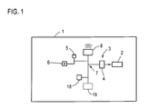
- Fig. 1 shows a schematic diagram of a motor vehicle according to the invention 1.
- the motor vehicle 1 comprises, as basically known, a motor 2, here a conventional internal combustion engine.
- a start-stop system 3 with a control unit 4 is designed to switch off the engine 2 when the motor vehicle is at a standstill, for example in a traffic jam.
- a specific operation such as pedaling a clutch pedal 5 and engaging a gear via a gear selector 6, the start-stop system 3 can be informed that the engine 2 should be started again.
- control unit 4 for carrying out the invention Is formed, for which the control unit 4 is connected via a bus system 7, in particular with a communication device 8 for the vehicle-to-vehicle communication (car2car communication).
- the communication device 8 can receive information from other road users up to a distance of 100 m or more, in particular also movement state information of other road users that can be evaluated in the control device 4, in the present case on the one hand in order to basically detect a traffic jam situation in which the motor vehicle 1, but also to determine a traffic jam information describing a resolution and / or a movement phase of the traffic jam from the movement state information.
- the movement state information is first filtered to the effect that only the road users are taken into account, which are in front of the own motor vehicle 1 on the track of the own motor vehicle 1, which with the help of the representation in Fig. 2 will be explained in more detail.
- a road 9 is shown having two lanes 10 and 11 leading in the same direction.
- the motor vehicle 1 is located on the left lane 10.
- Relevant for the assessment of the presence of a movement phase or a resolution of the congestion are only the motor vehicle on the track 10 leading road users 12.
- Road users 13 behind the motor vehicle 1 or road user 14 on the Neighbor track 11 are not taken into account, that is, their movement state information is not included in the calculations for determining congestion information.
- the movement state information here includes, in addition to the track 10, 11 of the road user 12, 13, 14 containing position of the respective road user 12, 13, 14, the current speed, in Fig. 2 is indicated by the arrows 15. Also, the current acceleration may be included in the motion state information. Incidentally, the motor vehicle 1 itself sends out its own movement state information via the communication device 8.
- This position and speed of the approach point 17 are now evaluated in the embodiment shown here on the basis of a condition to decide whether the engine 2 should be started automatically and a corresponding visual, audible and / or haptic information to be output to the driver, so this can prepare physically and mentally for the upcoming start-up process.
- the speed of the virtual approach point 17 is assumed to be constant in a look-ahead, wherein, for example, the currently determined value for the speed of the approach point 17 or an averaged value for the speed of the approach point 17 can be used, one of the speed-dependent threshold for the distance of the approach point 17 determined by the motor vehicle 1. If it results that the currently determined distance of the approach point 17 from the motor vehicle 1 falls below this threshold value, then the engine 2 is restarted and the above-described hint is output via a corresponding display device 18, via which the control unit 4 is also connected by means of the bus system 7. It should be noted at this point that of course also other vehicle systems 19 are connected to the bus system 7.
- a possible representation 20 shows this Fig. 3 , There, the own lane 10 is schematically shown with the road users 12 also indicated only schematically. The current position of the approach point 17 is indicated by a bar 21, which is constantly updated.
Landscapes
- Engineering & Computer Science (AREA)
- Chemical & Material Sciences (AREA)
- Combustion & Propulsion (AREA)
- Mechanical Engineering (AREA)
- Transportation (AREA)
- Health & Medical Sciences (AREA)
- Automation & Control Theory (AREA)
- Life Sciences & Earth Sciences (AREA)
- Atmospheric Sciences (AREA)
- Environmental & Geological Engineering (AREA)
- Toxicology (AREA)
- General Engineering & Computer Science (AREA)
- Control Of Vehicle Engines Or Engines For Specific Uses (AREA)
- Traffic Control Systems (AREA)
- Hybrid Electric Vehicles (AREA)
Abstract
Description
- Die Erfindung betrifft ein Verfahren zum Betrieb eines Start-Stopp-Systems eines Kraftfahrzeugs, welches zum Ausschalten des Motors des Kraftfahrzeugs in einer Standphase des Kraftfahrzeugs ausgebildet ist, sowie ein Kraftfahrzeug mit einem Start-Stopp-System.
- Start-Stopp-Systeme sind für Kraftfahrzeuge heute bereits weithin bekannt und werden auch in Serienfahrzeugen bereits eingesetzt. Diese Systeme zeichnen sich dadurch aus, dass der Motor des Kraftfahrzeugs in Stillstandsphasen abgeschaltet wird, beispielsweise dann, wenn das Kraftfahrzeug an einer Ampel wartet oder im Stau stillsteht und der Fahrer keinen Gang eingelegt hat. Dabei wird in im Stand der Technik bekannten Start-Stopp-Systemen der Motor in Reaktion auf eine Bedienhandlung des Fahrers neu gestartet. Bekannt ist es beispielsweise, als Bedienhandlung für einen Neustart des Motors eine Betätigung des Kupplungspedals und das Einlegen eines Ganges (einer Fahrstufe) zu fordern.
- Gerade in Staus und ähnlichen Verkehrssituationen ist ein derartiges Vorgehen jedoch nachteilhaft, da der Fahrer das Ende des Staus, dessen Auflösung bzw. Bewegungsphasen innerhalb des Staus nicht direkt einsehen kann, so dass der Motor häufig erst zu dem Zeitpunkt neu gestartet wird, zu dem der direkt vor dem eigenen Kraftfahrzeug befindliche Verkehrsteilnehmer wieder anfährt. Dies hat zur Folge, dass der gesamte Prozess des "Wiederanfahrens" unnötig verlängert wird. Mithin werden Staus langsamer aufgelöst oder durch langsameres Vorankommen innerhalb des Staus verlängert und dergleichen.
- Der Erfindung liegt daher die Aufgabe zugrunde, den Betrieb eines Start-Stopp-Systems dahingehend zu verbessern, dass der zeitliche Ablauf eines Neustarts in einer Stausituation optimiert wird.
- Zur Lösung dieser Aufgabe ist bei einem Verfahren der eingangs genannten Art erfindungsgemäß vorgesehen, dass in einer detektierten Stausituation über wenigstens eine drahtlose Kommunikationseinrichtung von vor dem eigenen Kraftfahrzeug befindlichen weiteren Verkehrsteilnehmern empfangene Bewegungszustandsinformationen der weiteren Verkehrsteilnehmer zur Ermittlung einer eine Auflösung und/oder Bewegungsphase des Staus beschreibenden Stauinformation ausgewertet werden und ein automatisches Starten des Motors und/oder eine Ausgabe eines Hinweises an den Fahrer in Abhängigkeit der Stauinformation erfolgt.
- Die vorliegende Erfindung schlägt mithin vor, eine Fahrzeug-zu-Fahrzeug-Kommunikation (car2car-Kommunikation) zu nutzen, um die Verkehrssituation zu analysieren und den Betrieb des Start-Stopp-Systems dahingehend zu optimieren. Hierfür kann das erfindungsgemäße Verfahren beispielsweise in einem Steuergerät des Start-Stopp-Systems ausgeführt werden. Über eine der Fahrzeug-zu-Fahrzeug-Kommunikation zugeordnete Kommunikationseinrichtung werden mithin Bewegungszustandsinformationen (Bewegungsprofile) umliegender Fahrzeuge bzw. Verkehrsteilnehmer drahtlos empfangen und bezüglich der aktuellen Situation ausgewertet. Dabei ist es besonders vorteilhaft, wenn alle umliegenden Verkehrsteilnehmer zur Fahrzeug-zu-Fahrzeug-Kommunikation ausgebildet sind, so dass die Bewegungszustandsinformationen aller Verkehrsteilnehmer, die vor dem Kraftfahrzeug auf der Spur des Kraftfahrzeugs innerhalb der Kommunikationsreichweite vorhanden sind, empfangen und ausgewertet werden. Sind nicht alle Kraftfahrzeuge zur Fahrzeug-zu-Fahrzeug-Kommunikation ausgebildet, so werden mit besonderem Vorteil zur Ermittlung der Stauinformation die Bewegungszustandsinformationen aller zur Fahrzeug-zu-Fahrzeug-Kommunikation ausgebildeten Verkehrsteilnehmer, die sich vor dem Kraftfahrzeug auf der Spur des Kraftfahrzeugs innerhalb der Kommunikationsreichweite befinden, ausgewertet. Dabei sei an dieser Stelle zum einen darauf hingewiesen, dass selbstverständlich auch das eigene Kraftfahrzeug durch andere Verkehrsteilnehmer nutzbare Bewegungszustandsinformationen aussenden kann, wobei die Bewegungszustandsinformationen selbstverständlich auch zu anderen Zwecken ausgewertet werden können. Zum anderen kann selbstverständlich vorgesehen sein, dass auch zur Detektion der Stausituation an sich die Bewegungszustandsinformationen der weiteren Verkehrsteilnehmer, insbesondere der Verkehrsteilnehmer, die vor dem Kraftfahrzeug auf der Spur des Kraftfahrzeugs befindlich sind, ausgewertet werden.
- Im Rahmen des erfindungsgemäßen Verfahrens wird also in Szenarien zusätzlich eingegriffen, in denen das Start-Stopp-System den Motor aufgrund eines Anhaltens in einem Stau abgestellt hat. Anhand der Fahrzeug-zu-Fahrzeug-Kommunikation erkennt das Steuergerät die Bewegungsprofile der Kraftfahrzeuge in seinem Umfeld. Wird nun bei der Auswertung der Bewegungszustandsinformationen, wozu beispielsweise geeignete Algorithmen und/oder Hardwarekomponenten in dem Steuergerät des Start-Stopp-Systems vorgesehen sein können, erkannt, dass viele andere Verkehrsteilnehmer in einer bestimmten örtlichen oder zeitlichen Vorausschau insbesondere korreliert vom stillstehenden in den fahrenden Zustand übergehen, so ist eine Auflösung bzw. Bewegungsphase des Staus detektierbar, so dass entsprechende Maßnahmen ergriffen werden können, die zu einem früheren Starten des Motors führen.
- Dabei ist es zunächst bevorzugt denkbar, dass der Motor präventiv, beispielsweise bei Erfüllung einer bestimmten, die Stauinformation auswertenden Bedingung, präventiv wieder gestartet wird, um schnellstmöglich ein Anfahren zu ermöglichen, so dass die Zeit zur Stauauflösung bzw. zum Übergang in die Bewegungsphase minimiert wird. Zusätzlich oder alternativ kann jedoch auch vorgesehen sein, dass eine Ausgabe eines Hinweises an den Fahrer bezüglich der Auflösung und/oder Bewegungsphase des Staus ausgegeben wird, so dass dieser, falls kein automatisches Wiederanlassen des Motors vorgesehen ist, entsprechende Maßnahmen ergreifen kann, um zeitnah selbst wieder anzufahren und somit den Zeitablauf zu optimieren. Der Motor wird somit aufgrund einer Bedienhandlung des Fahrers nicht erst dann gestartet, wenn der Vordermann anfährt, sondern das Anlassen des Motors aufgrund der Bedienhandlung kann bereits früher geschehen, so dass auch hier die Zeit zum Wiederanfahren und zur Auflösung des Staues verringert wird.
- Durch das präventive Neustarten des Motors des Kraftfahrzeugs, welches insbesondere automatisch vorgenommen wird, kann das Anfahren zügig und ohne größere Verzögerung durchgeführt werden. Dadurch verringert sich insgesamt die Zeit, die zur Auflösung des Staus bzw. zum Übergang in die Bewegungsphase benötigt wird. Durch das Starten des Motors bzw. die Information wird zudem die Aufmerksamkeit des Fahrers auf das Verkehrsgeschehen gelenkt, so dass er sich psychisch und physisch auf die Weiterfahrt einstellen kann.
- In besonders vorteilhafter Ausgestaltung der vorliegenden Erfindung kann vorgesehen sein, dass die Position und/oder Geschwindigkeit eines vor dem Kraftfahrzeug befindlichen Anfahrpunktes als Stauinformation ermittelt wird. Fahren Fahrzeuge, welche in einer Schlange stehen, nacheinander von vorne her an, kann ein virtueller Punkt detektiert werden, an dem Kraftfahrzeuge vom stillstehenden in den fahrenden Zustand übergehen, also ein Anfahrpunkt. Durch Analyse der Bewegungszustandsinformationen, welche insbesondere eine Geschwindigkeit und eine Position umfassen können, kann nun die Position und die zeitliche Entwicklung des Anfahrpunktes ermittelt werden. Üblicherweise wird sich der Anfahrpunkt mit einer im Wesentlichen konstanten Geschwindigkeit auf das Kraftfahrzeug zu bewegen.
- Als Bedingung für das Starten des Motors und/oder die Ausgabe des Hinweises kann zweckmäßigerweise die Unterschreitung eines insbesondere von der Geschwindigkeit des Anfahrpunktes abhängigen Schwellwerts durch den Abstand des Anfahrpunktes von dem eigenen Kraftfahrzeug vorgesehen sein, das bedeutet, dass im Wesentlichen zwei Ausgestaltungen denkbar sind. So kann das Verfahren zum einen so ausgeprägt sein, dass dann, wenn sich der Anfahrpunkt in einer festen Entfernung zum Kraftfahrzeug befindet, der Motor wieder gestartet wird (bzw. die Ausgabe des Hinweises erfolgt). Denkbar und erfindungsgemäß bevorzugt ist es jedoch, wenn die Geschwindigkeit des virtuellen Anfahrpunktes, die als in Zukunft konstant angenommen werden kann, mit berücksichtigt wird. Dann kann bei Annahme einer konstanten Geschwindigkeit des virtuellen Anfahrpunkts in der Richtung auf das eigene Kraftfahrzeug zu in einer gewissen zeitlichen Vorausschau der Motor gestartet werden (TTS - time to start). Hängt der Startzeitpunkt des Motors bzw. die Ausgabe des Hinweises bei der ersten Variante also rein von der Entfernung der Stauauflösung, allgemein des virtuellen Anfahrpunktes, ab, so fließt in der zweiten Variante auch die Geschwindigkeit der Stauauflösung, allgemein des Anfahrpunktes, mit ein.
- Als Bewegungszustandsinformationen können eine Geschwindigkeit und/oder eine Position und/oder eine Beschleunigung empfangen werden. Die Position kann dabei beliebig aufgeschlüsselt sein, wobei es sich im Rahmen der vorliegenden Erfindung, insbesondere bei mehrspurigen Straßen, auf denen es staut, anbietet, dass die Positionsinformation auch eine Fahrspurinformation enthält. Ansonsten können Positionen beispielsweise anhand von GPS-Koordinaten, Kartendaten und/oder auch als relative Position zum eigenen Kraftfahrzeug wiedergegeben werden. Auch eine aktuelle Geschwindigkeit oder eine aktuelle Beschleunigung können im Rahmen der vorliegenden Erfindung verarbeitet werden, wobei die hier genannten möglichen Bewegungszustandsinformationen selbstverständlich auch für andere Fahrzeugsysteme nützlich über die Fahrzeug-zu-Fahrzeug-Kommunikation übertragen werden können.
- Wie bereits erwähnt, ist die Kommunikationseinrichtung zweckmäßig eine Fahrzeug-zu-Fahrzeug-Kommunikationseinrichtung. Besonders vorteilhaft ist es, wenn die Reichweite der Kommunikation größer als 50 m, insbesondere größer als 100 m, ist. Je weiter sozusagen im Voraus Bewegungszustandsinformationen erhalten werden können, desto genauer ist es beispielsweise möglich, die Position und gegebenenfalls Geschwindigkeit des Anfahrpunktes zu ermitteln. Gegebenenfalls kann dann auch festgestellt werden, ob es sich um eine Bewegungsphase innerhalb eines Staus oder die Auflösung des Staus handelt. Dabei sei in diesem Zusammenhang darauf hingewiesen, dass es selbstverständlich auch möglich ist, die Bewegungszustandsinformationen über eine Art "Hopping" über die eigentliche Reichweite der Kommunikation hinaus zu übertragen, indem letztlich Kraftfahrzeuge empfangene Bewegungszustandsinformationen anderer Verkehrsteilnehmer weiter verbreiten. Als konkrete Kommunikationsnetzwerke bzw. Kommunikationsverbindungen können bereits im Rahmen der Fahrzeug-zu-Fahrzeug-Kommunikation vorgeschlagene Standards eingesetzt werden, beispielsweise der WLAN 802.11 p-Standard.
- Bezüglich des Hinweises kann vorgesehen sein, dass dieser optisch und/oder akustisch und/oder haptisch ausgegeben wird, insbesondere über ein Head-Up-Display. Verschiedene Arten von Hinweisen sind denkbar, um die Aufmerksamkeit des Fahrers auf den bevorstehenden Anfahrzeitpunkt zu richten bzw. die Tatsache, dass der Motor automatisch angelassen wurde. Bevorzugt sind hierbei optische Anzeigen, die beispielsweise auch in Form einer graphischen Darstellung kodiert die Position und/oder Geschwindigkeit des Anfahrpunktes darstellen können, so dass der Fahrer trotz gegebenenfalls die Sicht versperrenden direkten Vorderfahrzeugen einen Hinweis darauf erhält, wann eine Bewegungsphase oder die Auflösung des Staus erfolgt. Möglich ist beispielsweise eine abstrahierte Darstellung der eigenen Fahrspur und der voranfahrenden Verkehrsteilnehmer, die überlagert von eine den Anfahrpunkt markierenden Linie bzw. einer Darstellung des Anfahrpunktes und dessen zeitlicher Entwicklung dargestellt wird.
- Neben dem Verfahren betrifft die Erfindung auch ein Kraftfahrzeug, umfassend eine Kommunikationseinrichtung zur Kommunikation mit anderen Verkehrsteilnehmern und ein Start-Stopp-System mit einem zur Durchführung des erfindungsgemäßen Verfahren ausgebildeten Steuergerät. Sämtliche Ausführungen bezüglich des erfindungsgemäßen Verfahrens lassen sich analog auf das erfindungsgemäße Kraftfahrzeug übertragen, so dass auch hier die genannten Vorteile erreicht werden können.
- Über die Kommunikationseinrichtung werden mithin Bewegungszustandsinformationen anderer Verkehrsteilnehmer empfangen, welche dann auch an das Steuergerät weitergeleitet werden, beispielsweise über ein Bussystem, insbesondere einen CAN-Bus. Dort kann beispielsweise vorgesehen sein, dass die Bewegungszustandsinformationen zunächst vorgefiltert werden, so dass nur die sich auf derselben Spur wie das Kraftfahrzeug vor dem Kraftfahrzeug befindlichen Verkehrsteilnehmer in der weiteren Analyse berücksichtigt werden. Das Steuergerät ist sodann zur Ermittlung der Stauinformation aus den Bewegungszustandsinformationen ausgebildet, beispielsweise zur Ermittlung der Position und gegebenenfalls Geschwindigkeit eines vor dem Kraftfahrzeug befindlichen Anfahrpunktes, wobei die Stauinformation dann bezüglich eines Kriteriums, beispielsweise des diskutierten Schwellwerts, weiter ausgewertet werden kann. Ist das Kriterium erfüllt, erfolgt eine Ansteuerung des Motors des Kraftfahrzeugs zum Starten und/oder der Anzeigevorrichtung zur Ausgabe des Hinweises.
- Weitere Vorteile und Einzelheiten der vorliegenden Erfindung ergeben sich aus den im Folgenden beschriebenen Ausführungsbeispielen sowie anhand der Zeichnungen. Dabei zeigen:
- Fig. 1
- eine Prinzipskizze eines erfindungsgemäßen Kraftfahrzeugs,
- Fig. 2
- eine Skizze zur Definition eines Anfahrpunktes, und
- Fig. 3
- eine mögliche Darstellung zur Information und Ausgabe eines Hinweises an den Fahrer.
-
Fig. 1 zeigt eine Prinzipskizze eines erfindungsgemäßen Kraftfahrzeugs 1. Das Kraftfahrzeug 1 umfasst, wie grundsätzlich bekannt, einen Motor 2, hier einen üblichen Verbrennungsmotor. Ein Start-Stopp-System 3 mit einem Steuergerät 4 ist dazu ausgebildet, den Motor 2 bei Stillstand des Kraftfahrzeugs, beispielsweise in einem Stau, auszuschalten. Durch eine bestimmte Bedienhandlung, beispielsweise das Treten eines Kupplungspedals 5 und das Einlegen eines Ganges über einen Gangwahlhebel 6 kann dem Start-Stopp-System 3 mitgeteilt werden, dass der Motor 2 wieder angelassen werden soll. - Nachdem gerade in Stausituationen es für den Fahrer häufig erst mit dem Losfahren des unmittelbar vor ihm auf der eigenen Spur befindlichen Verkehrsteilnehmers ersichtlich ist, dass er selber losfahren muss, ergeben sich Zeitverzögerungen, wobei, um diese zu vermeiden, das Steuergerät 4 zur Durchführung des erfindungsgemäßen Verfahrens ausgebildet ist, wozu das Steuergerät 4 über ein Bussystem 7 insbesondere auch mit einer Kommunikationseinrichtung 8 für die Fahrzeug-zu-Fahrzeug-Kommunikation (car2car-Kommunikation) verbunden ist.
- Die Kommunikationseinrichtung 8 kann dabei Informationen anderer Verkehrsteilnehmer bis hin zu einem Abstand von 100 m oder mehr empfangen, insbesondere auch Bewegungszustandsinformationen anderer Verkehrsteilnehmer, die im Steuergerät 4 ausgewertet werden können, vorliegend zum einen, um eine Stausituation grundsätzlich zu detektieren, in der sich das Kraftfahrzeug 1 befindet, zum anderen aber auch, um eine eine Auflösung und/oder Bewegungsphase des Staus beschreibende Stauinformation aus den Bewegungszustandsinformationen zu ermitteln. Hierzu werden die Bewegungszustandsinformationen zunächst dahingehend gefiltert, dass nur die Verkehrsteilnehmer berücksichtigt werden, die sich vor dem eigenen Kraftfahrzeug 1 auf der Spur des eigenen Kraftfahrzeugs 1 befinden, was mit Hilfe der Darstellung in
Fig. 2 näher erläutert werden soll. - Dort ist eine Straße 9 gezeigt, die zwei in dieselbe Richtung führende Fahrspuren 10 und 11 aufweist. Das Kraftfahrzeug 1 befindet sich dabei auf der linken Fahrspur 10. Relevant für die Beurteilung des Vorhandenseins einer Bewegungsphase bzw. einer Auflösung des Staus sind nur die dem Kraftfahrzeug auf der Spur 10 voranfahrenden Verkehrsteilnehmer 12. Verkehrsteilnehmer 13 hinter dem Kraftfahrzeug 1 oder Verkehrsteilnehmer 14 auf der Nachbarspur 11 werden nicht berücksichtigt, das bedeutet, ihre Bewegungszustandsinformationen fließen nicht in die Berechnungen zur Ermittlung der Stauinformation ein.
- Die Bewegungszustandsinformationen umfassen vorliegend neben der auch die Spur 10, 11 des Verkehrsteilnehmers 12, 13, 14 enthaltenden Position des jeweiligen Verkehrsteilnehmers 12, 13, 14 die aktuelle Geschwindigkeit, die in
Fig. 2 durch die Pfeile 15 angedeutet ist. Auch die aktuelle Beschleunigung kann in den Bewegungszustandsinformationen enthalten sein. Das Kraftfahrzeug 1 sendet im Übrigen selbst über die Kommunikationseinrichtung 8 seine eigenen Bewegungszustandsinformationen aus. - Ersichtlich befindet sich in der in
Fig. 2 dargestellten Situation der Stau gerade in einer Auflösung, das bedeutet, die rechts inFig. 2 dargestellten Verkehrsteilnehmer 12, 14 bewegen sich bereits wieder mit einer gewissen Geschwindigkeit. Einer der Verkehrsteilnehmer 12, hier das Fahrzeug 16, auf der Fahrspur 10 des Kraftfahrzeugs 1 ist gerade im Begriff, anzufahren. Mithin kann nun ein virtueller Anfahrpunkt 17 definiert werden, der hier bei dem Fahrzeug 16 liegt. Durch Betrachtung insbesondere auch des zeitlichen Verlaufs der Bewegungszustandsinformationen kann das Steuergerät 4 nicht nur die aktuelle Position des Anfahrpunktes 17 ermitteln, sondern auch dessen Geschwindigkeit, welche im Wesentlichen konstant sein dürfte. Diese Position und Geschwindigkeit des Anfahrpunktes 17 werden nun im hier dargestellten Ausführungsbeispiel anhand einer Bedingung ausgewertet, um zu entscheiden, ob der Motor 2 automatisch gestartet werden soll und ein entsprechender optischer, akustischer und/oder haptischer Hinweis an den Fahrer ausgegeben werden soll, damit dieser sich physisch und psychisch auf den bevorstehenden Anfahrvorgang vorbereiten kann. - Vorliegend wird dabei unter der Annahme, dass die Geschwindigkeit des virtuellen Anfahrpunktes 17 in einer Vorausschau als konstant angenommen wird, wobei beispielsweise der aktuell bestimmte Wert für die Geschwindigkeit des Anfahrpunktes 17 oder ein gemittelter Wert für die Geschwindigkeit des Anfahrpunktes 17 herangezogen werden kann, ein von der Geschwindigkeit abhängiger Schwellwert für den Abstand des Anfahrpunktes 17 vom Kraftfahrzeug 1 ermittelt. Ergibt sich, dass der aktuell ermittelte Abstand des Anfahrpunktes 17 von dem Kraftfahrzeug 1 diesen Schwellwert unterschreitet, so wird der Motor 2 wieder angelassen und der oben beschriebene Hinweis wird über eine entsprechende Anzeigevorrichtung 18 ausgegeben, über die das Steuergerät 4 auch mittels des Bussystems 7 verbunden ist. Es sei an dieser Stelle angemerkt, dass an das Bussystem 7 selbstverständlich auch weitere Fahrzeugsysteme 19 angeschlossen sind.
- Dabei sei an dieser Stelle noch darauf hingewiesen, dass im Rahmen der Erfindung auch eine ständige Anzeige und somit Information des Fahrers des Kraftfahrzeugs 1 erreicht werden kann, indem über die Anzeigevorrichtung 18 die Stauinformation, hier eine Information bezüglich des virtuellen Anfahrpunktes, dem Fahrer über eine Darstellung zur Kenntnis gebracht wird.
- Eine mögliche Darstellung 20 hierzu zeigt
Fig. 3 . Dort ist schematisch die eigene Fahrspur 10 mit den ebenso nur schematisch angedeuteten Verkehrsteilnehmern 12 gezeigt. Die aktuelle Position des Anfahrpunktes 17 wird durch einen Balken 21, der ständig aktualisiert wird, verdeutlicht.
Claims (7)
- Verfahren zum Betrieb eines Start-Stopp-Systems (3) eines Kraftfahrzeugs (1), welches zum Ausschalten des Motors (2) des Kraftfahrzeugs (1) in einer Standphase des Kraftfahrzeugs (1) ausgebildet ist,
dadurch gekennzeichnet,
dass in einer detektierten Stausituation über wenigstens eine drahtlose Kommunikationseinrichtung (8) von vor dem eigenen Kraftfahrzeug (1) befindlichen weiteren Verkehrsteilnehmern (12) empfangene Bewegungszustandsinformationen der weiteren Verkehrsteilnehmer (12) zur Ermittlung einer eine Auflösung und/oder Bewegungsphase des Staus beschreibenden Stauinformation ausgewertet werden und ein automatisches Starten des Motors (2) und/oder eine Ausgabe eines Hinweises an den Fahrer in Abhängigkeit der Stauinformation erfolgt. - Verfahren nach Anspruch 1, dadurch gekennzeichnet, dass die Position und/oder Geschwindigkeit eines vor dem Kraftfahrzeug (1) befindlichen Anfahrpunktes (17) als Stauinformation ermittelt wird.
- Verfahren nach Anspruch 2, dadurch gekennzeichnet, dass das Starten des Motors (2) und/oder die Ausgabe des Hinweises bei Unterschreitung eines insbesondere von der Geschwindigkeit des Anfahrpunktes (17) abhängigen Schwellwerts durch den Abstand des Anfahrpunktes (17) von dem eigenen Kraftfahrzeug (1) erfolgt.
- Verfahren nach einem der vorangehenden Ansprüche, dadurch gekennzeichnet, dass als Bewegungszustandsinformation eine Geschwindigkeit und/oder eine Position und/oder eine Beschleunigung empfangen wird.
- Verfahren nach einem der vorangehenden Ansprüche, dadurch gekennzeichnet, dass die Kommunikationseinrichtung (8) eine Fahrzeug-zu-Fahrzeug-Kommunikationseinrichtung (8) ist und/oder die Reichweite der Kommunikation größer als 50 m, insbesondere größer als 100 m, ist.
- Verfahren nach einem der vorangehenden Ansprüche, dadurch gekennzeichnet, dass der Hinweis optisch und/oder akustisch und/oder haptisch ausgegeben wird, insbesondere über ein Head-Up-Display.
- Kraftfahrzeug (1), umfassend eine Kommunikationseinrichtung (8) zur Kommunikation mit anderen Verkehrsteilnehmern (12, 13, 14) und ein Start-Stopp-System (3) mit einem zur Durchführung eines Verfahrens nach einem der vorangehenden Ansprüche ausgebildeten Steuergerät (4).
Applications Claiming Priority (1)
| Application Number | Priority Date | Filing Date | Title |
|---|---|---|---|
| DE102011118252A DE102011118252A1 (de) | 2011-11-11 | 2011-11-11 | Verfahren zum Betrieb eines Start-Stopp-Systems eines Kraftfahrzeugs und Kraftfahrzeug |
Publications (2)
| Publication Number | Publication Date |
|---|---|
| EP2592261A1 true EP2592261A1 (de) | 2013-05-15 |
| EP2592261B1 EP2592261B1 (de) | 2015-02-25 |
Family
ID=46939455
Family Applications (1)
| Application Number | Title | Priority Date | Filing Date |
|---|---|---|---|
| EP12006441.5A Not-in-force EP2592261B1 (de) | 2011-11-11 | 2012-09-14 | Verfahren zum Betrieb eines Start-Stopp-Systems eines Kraftfahrzeugs und Kraftfahrzeug |
Country Status (5)
| Country | Link |
|---|---|
| US (1) | US20130124071A1 (de) |
| EP (1) | EP2592261B1 (de) |
| CN (1) | CN103101539B (de) |
| DE (1) | DE102011118252A1 (de) |
| ES (1) | ES2533379T3 (de) |
Cited By (1)
| Publication number | Priority date | Publication date | Assignee | Title |
|---|---|---|---|---|
| WO2022229534A1 (fr) * | 2021-04-30 | 2022-11-03 | Psa Automobiles Sa | Procédé et dispositif de contrôle d'un système d'arrêt-démarrage automatique de moteur dans un groupement de véhicules par peloton |
Families Citing this family (17)
| Publication number | Priority date | Publication date | Assignee | Title |
|---|---|---|---|---|
| JP6082638B2 (ja) * | 2013-03-29 | 2017-02-15 | 日立オートモティブシステムズ株式会社 | 走行制御装置及び走行制御システム |
| US9447741B2 (en) * | 2014-01-17 | 2016-09-20 | Ford Global Technologies, Llc | Automatic engine start-stop control |
| DE102014003167A1 (de) | 2014-03-03 | 2015-03-26 | Audi Ag | Verfahren für den Betrieb eines Start-Stopp-Systems und zugehöriges Start-Stopp-System |
| DE102015009465A1 (de) | 2015-07-22 | 2017-01-26 | Audi Ag | Verfahren und Vorrichtung zur Unterstzützung eines Fahrers eines Fahrzeugs, insbesondere eines Kraftfahrzeugs |
| DE102015222805A1 (de) | 2015-11-19 | 2017-05-24 | Volkswagen Aktiengesellschaft | Automatische Steuerung eines Fahrzeugs beim Anfahren |
| CN105405286A (zh) * | 2015-12-04 | 2016-03-16 | 广州汽车集团股份有限公司 | 发动机智能起停控制方法及发动机智能起停系统 |
| DE102016200897A1 (de) | 2016-01-22 | 2017-07-27 | Bayerische Motoren Werke Aktiengesellschaft | Verfahren und Vorrichtung zum zumindest teilweise automatisierten Fahren |
| CN105799704A (zh) * | 2016-03-11 | 2016-07-27 | 京东方科技集团股份有限公司 | 车辆控制方法、控制装置、车载系统以及车辆控制系统 |
| DE102017200602B4 (de) | 2017-01-17 | 2023-02-02 | Audi Ag | Prognostizieren einer voraussichtlichen Haltezeit für ein Start-Stopp-System eines Kraftfahrzeugs |
| DE102017204256A1 (de) * | 2017-03-14 | 2018-09-20 | Bayerische Motoren Werke Aktiengesellschaft | Verfahren und Vorrichtung zur Erinnerung eines Fahrers an ein Anfahren an einer Lichtsignaleinrichtung mit variabler Ausgabefunktion |
| US20180273047A1 (en) * | 2017-03-27 | 2018-09-27 | Ford Global Technologies, Llc | Vehicle propulsion operation |
| CN107215338A (zh) * | 2017-06-16 | 2017-09-29 | 奇瑞汽车股份有限公司 | 一种汽车的启停控制系统及控制方法 |
| JP6801627B2 (ja) * | 2017-10-25 | 2020-12-16 | トヨタ自動車株式会社 | 車両 |
| KR20190072932A (ko) * | 2017-12-18 | 2019-06-26 | 현대자동차주식회사 | 마일드 하이브리드 차량의 제어 방법 |
| CN111396224B (zh) * | 2019-01-03 | 2022-07-15 | 奥迪股份公司 | 控制车辆发动机的关闭与启动的方法、装置和存储介质 |
| CN110816440B (zh) * | 2019-10-23 | 2021-04-02 | 上海能塔智能科技有限公司 | 基于车辆状态的数据处理方法、装置、设备与存储介质 |
| CN114162124B (zh) * | 2020-08-19 | 2024-07-19 | 奥迪股份公司 | 用于车辆启停控制的辅助驾驶系统、方法和存储介质 |
Citations (5)
| Publication number | Priority date | Publication date | Assignee | Title |
|---|---|---|---|---|
| DE19942371A1 (de) * | 1999-09-04 | 2001-03-08 | Valeo Schalter & Sensoren Gmbh | Verfahren und Vorrichtung zum Erkennen des möglichen Anfahrens eines Kraftfahrzeugs |
| WO2003001055A1 (de) * | 2001-06-21 | 2003-01-03 | Conti Temic Microelectronic Gmbh | Automatisches motor-abschalt-/anlassersystem für kraftfahrzeuge sowie verfahren zu dessen betrieb |
| DE102006009654A1 (de) * | 2006-03-02 | 2007-11-08 | Robert Bosch Gmbh | Vorrichtung zum An- und Abschalten eines Fahrzeugmotors in Abhängigkeit von der Verkehrssituation |
| DE102009042309A1 (de) * | 2008-10-15 | 2010-04-29 | Continental Teves Ag & Co. Ohg | Verfahren und Vorrichtung zur automatischen Motorsteuerung eines Fahrzeugs |
| JP2010138786A (ja) * | 2008-12-11 | 2010-06-24 | Denso Corp | アイドリング停止通知装置 |
Family Cites Families (15)
| Publication number | Priority date | Publication date | Assignee | Title |
|---|---|---|---|---|
| JP2868974B2 (ja) * | 1993-06-16 | 1999-03-10 | 三菱電機株式会社 | エンジンの自動始動停止装置 |
| JP3675235B2 (ja) * | 1999-06-30 | 2005-07-27 | 日産自動車株式会社 | 車両用走行制御装置 |
| JP2001107770A (ja) * | 1999-10-08 | 2001-04-17 | Honda Motor Co Ltd | エンジン制御装置 |
| DE10139595A1 (de) * | 2001-08-11 | 2003-02-27 | Bosch Gmbh Robert | Vorrichtung zum automatischen Einschalten und Ausschalten einer Brennkraftmaschine |
| US6882923B2 (en) * | 2002-10-17 | 2005-04-19 | Ford Global Technologies, Llc | Adaptive cruise control system using shared vehicle network data |
| US7831369B2 (en) * | 2005-11-16 | 2010-11-09 | Gm Global Technology Operations, Inc. | Method and apparatus for vehicle and engine operation |
| WO2007074197A1 (es) * | 2005-12-29 | 2007-07-05 | Consejo Superior De Investigaciones Científicas | Aparato de control de un automóvil, con ayuda de gps y comunicaciones inalámbricas, que permite circular en tráfico con retenciones |
| US20090271087A1 (en) * | 2006-11-29 | 2009-10-29 | Yutaka Motonaga | Control device and engine control device |
| DE102008011709B4 (de) * | 2008-02-28 | 2011-02-10 | Siemens Aktiengesellschaft | Vorrichtung zur Steuerung zumindest eines Energieverbrauchers in einem Verkehrsmittel, insbesondere in einem Kraftfahrzeug |
| DE102008042306A1 (de) * | 2008-09-24 | 2010-04-01 | Robert Bosch Gmbh | Verfahren zum Umsetzen einer Start-Stopp-Automatik |
| DE102009040160B4 (de) * | 2009-09-04 | 2020-02-06 | Volkswagen Ag | Start-Stopp-Automatik und Verfahren zum Betreiben einer Start-Stopp-Automatik |
| DE102009050520B4 (de) * | 2009-10-23 | 2021-01-28 | Bayerische Motoren Werke Aktiengesellschaft | Verfahren zur Steuerung eines automatischen Abschalt- und Anschaltvorgangs einer Antriebseinheit in einem Kraftfahrzeug |
| US20110190972A1 (en) * | 2010-02-02 | 2011-08-04 | Gm Global Technology Operations, Inc. | Grid unlock |
| US8296030B2 (en) * | 2010-07-07 | 2012-10-23 | Robert Bosch Gmbh | System and method for controlling the engine of a vehicle |
| DE102011121442A1 (de) * | 2011-12-16 | 2013-06-20 | Gm Global Technology Operations, Llc | Autonomes Anfahren |
-
2011
- 2011-11-11 DE DE102011118252A patent/DE102011118252A1/de not_active Withdrawn
-
2012
- 2012-09-14 ES ES12006441.5T patent/ES2533379T3/es active Active
- 2012-09-14 EP EP12006441.5A patent/EP2592261B1/de not_active Not-in-force
- 2012-10-31 US US13/665,619 patent/US20130124071A1/en not_active Abandoned
- 2012-11-09 CN CN201210447621.5A patent/CN103101539B/zh not_active Expired - Fee Related
Patent Citations (5)
| Publication number | Priority date | Publication date | Assignee | Title |
|---|---|---|---|---|
| DE19942371A1 (de) * | 1999-09-04 | 2001-03-08 | Valeo Schalter & Sensoren Gmbh | Verfahren und Vorrichtung zum Erkennen des möglichen Anfahrens eines Kraftfahrzeugs |
| WO2003001055A1 (de) * | 2001-06-21 | 2003-01-03 | Conti Temic Microelectronic Gmbh | Automatisches motor-abschalt-/anlassersystem für kraftfahrzeuge sowie verfahren zu dessen betrieb |
| DE102006009654A1 (de) * | 2006-03-02 | 2007-11-08 | Robert Bosch Gmbh | Vorrichtung zum An- und Abschalten eines Fahrzeugmotors in Abhängigkeit von der Verkehrssituation |
| DE102009042309A1 (de) * | 2008-10-15 | 2010-04-29 | Continental Teves Ag & Co. Ohg | Verfahren und Vorrichtung zur automatischen Motorsteuerung eines Fahrzeugs |
| JP2010138786A (ja) * | 2008-12-11 | 2010-06-24 | Denso Corp | アイドリング停止通知装置 |
Cited By (2)
| Publication number | Priority date | Publication date | Assignee | Title |
|---|---|---|---|---|
| WO2022229534A1 (fr) * | 2021-04-30 | 2022-11-03 | Psa Automobiles Sa | Procédé et dispositif de contrôle d'un système d'arrêt-démarrage automatique de moteur dans un groupement de véhicules par peloton |
| FR3122389A1 (fr) * | 2021-04-30 | 2022-11-04 | Psa Automobiles Sa | Procédé et dispositif de contrôle d’un système d’arrêt-démarrage automatique de moteur dans un groupement de véhicules par peloton |
Also Published As
| Publication number | Publication date |
|---|---|
| EP2592261B1 (de) | 2015-02-25 |
| ES2533379T3 (es) | 2015-04-09 |
| US20130124071A1 (en) | 2013-05-16 |
| CN103101539B (zh) | 2016-03-02 |
| DE102011118252A1 (de) | 2013-05-16 |
| CN103101539A (zh) | 2013-05-15 |
Similar Documents
| Publication | Publication Date | Title |
|---|---|---|
| EP2592261B1 (de) | Verfahren zum Betrieb eines Start-Stopp-Systems eines Kraftfahrzeugs und Kraftfahrzeug | |
| EP3377380B1 (de) | Automatische steuerung eines fahrzeugs beim anfahren | |
| EP2714484B1 (de) | Verfahren zum betrieb eines längsführenden fahrerassistenzsystems eines kraftfahrzeugs und kraftfahrzeug | |
| DE102007029482B4 (de) | Fahrerassistenzsystem mit Anfahrhinweisfunktion | |
| EP2857247B1 (de) | Verfahren und Vorrichtung für ein zur automatischen Längsführung ausgestaltetes Fahrzeug | |
| DE102013110909A1 (de) | Vorrichtung zum automatischen Fahren eines Fahrzeugs | |
| DE102011084606A1 (de) | Bestimmung einer Fahrstrategie für ein Fahrzeug | |
| DE112016002612T5 (de) | Fahrzeugsteuervorrichtung, Fahrzeugsteuerverfahren und Fahrzeugsteuerprogramm | |
| DE102022115718A1 (de) | Verfahren und Vorrichtung zum automatisierten Anfahren eines Fahrzeugs an einer Signalisierungseinheit | |
| DE102012017526A1 (de) | Verfahren zum Betrieb eines Fahrzeuges | |
| DE102008042306A1 (de) | Verfahren zum Umsetzen einer Start-Stopp-Automatik | |
| DE102018125939A1 (de) | Verfahren und Steuereinheit zur Übergabe einer Fahraufgabe an einen Fahrer eines Fahrzeugs | |
| DE102015208432A1 (de) | Ampelanfahrtassistent | |
| DE102012016772A1 (de) | Geschwindigkeitsregelung eines Kraftfahrzeugs | |
| EP3630583A1 (de) | Fahrsystem zum automatisierten fahren mit einer lenkradanzeige zur anzeige der entfernung zu einem endpunkt für automatisiertes fahren und verfahren zur anzeige der entfernung | |
| DE102015219934A1 (de) | Kommunikation einer Fahrstreifenwechselabsicht | |
| DE102014003781B4 (de) | Fahrerassistenzsystem für ein Kraftfahrzeug und zugehöriges Betriebsverfahren | |
| DE102013200391B4 (de) | Verfahren und Vorrichtung zur adaptiven Geschwindigkeitsregelung eines Kraftfahrzeugs mit manuellem Schaltgetriebe | |
| DE102012016366A1 (de) | Verfahren zum Betreiben eines Fahrerassistenzsystems eines Kraftfahrzeugs und Fahrerassistenzsystem für ein Kraftfahrzeug | |
| DE102014216269A1 (de) | Verfahren zum automatischen Regeln des Fahrverhaltens von Fahrzeugen an einer Wechsellichtzeichenanlage | |
| WO2017108430A1 (de) | Verfahren zur situationsbasierten unterstützung eines kraftfahrzeuges zur bildung eines korridors für einsatzfahrzeuge | |
| DE102009021283A1 (de) | Vorrichtung und Verfahren zur Unterstützung eines Fahrzeugführers | |
| EP2835790B1 (de) | Verfahren und vorrichtung zur lenkzeitoptimierung bei fahrzeugen | |
| DE102015221607A1 (de) | Fahrerassistenzsystem | |
| DE102010035086B4 (de) | Verfahren zum Betrieb eines Geschwindigkeitsregelsystems eines Kraftfahrzeugs und Kraftfahrzeug |
Legal Events
| Date | Code | Title | Description |
|---|---|---|---|
| PUAI | Public reference made under article 153(3) epc to a published international application that has entered the european phase |
Free format text: ORIGINAL CODE: 0009012 |
|
| AK | Designated contracting states |
Kind code of ref document: A1 Designated state(s): AL AT BE BG CH CY CZ DE DK EE ES FI FR GB GR HR HU IE IS IT LI LT LU LV MC MK MT NL NO PL PT RO RS SE SI SK SM TR |
|
| AX | Request for extension of the european patent |
Extension state: BA ME |
|
| 17P | Request for examination filed |
Effective date: 20131115 |
|
| RBV | Designated contracting states (corrected) |
Designated state(s): AL AT BE BG CH CY CZ DE DK EE ES FI FR GB GR HR HU IE IS IT LI LT LU LV MC MK MT NL NO PL PT RO RS SE SI SK SM TR |
|
| 17Q | First examination report despatched |
Effective date: 20140602 |
|
| GRAP | Despatch of communication of intention to grant a patent |
Free format text: ORIGINAL CODE: EPIDOSNIGR1 |
|
| INTG | Intention to grant announced |
Effective date: 20141121 |
|
| GRAS | Grant fee paid |
Free format text: ORIGINAL CODE: EPIDOSNIGR3 |
|
| GRAA | (expected) grant |
Free format text: ORIGINAL CODE: 0009210 |
|
| AK | Designated contracting states |
Kind code of ref document: B1 Designated state(s): AL AT BE BG CH CY CZ DE DK EE ES FI FR GB GR HR HU IE IS IT LI LT LU LV MC MK MT NL NO PL PT RO RS SE SI SK SM TR |
|
| REG | Reference to a national code |
Ref country code: GB Ref legal event code: FG4D Free format text: NOT ENGLISH |
|
| REG | Reference to a national code |
Ref country code: CH Ref legal event code: EP |
|
| REG | Reference to a national code |
Ref country code: IE Ref legal event code: FG4D Free format text: LANGUAGE OF EP DOCUMENT: GERMAN |
|
| REG | Reference to a national code |
Ref country code: DE Ref legal event code: R096 Ref document number: 502012002307 Country of ref document: DE Effective date: 20150409 Ref country code: ES Ref legal event code: FG2A Ref document number: 2533379 Country of ref document: ES Kind code of ref document: T3 Effective date: 20150409 |
|
| REG | Reference to a national code |
Ref country code: AT Ref legal event code: REF Ref document number: 712221 Country of ref document: AT Kind code of ref document: T Effective date: 20150415 |
|
| REG | Reference to a national code |
Ref country code: NL Ref legal event code: VDEP Effective date: 20150225 |
|
| REG | Reference to a national code |
Ref country code: LT Ref legal event code: MG4D |
|
| PG25 | Lapsed in a contracting state [announced via postgrant information from national office to epo] |
Ref country code: NO Free format text: LAPSE BECAUSE OF FAILURE TO SUBMIT A TRANSLATION OF THE DESCRIPTION OR TO PAY THE FEE WITHIN THE PRESCRIBED TIME-LIMIT Effective date: 20150525 Ref country code: SE Free format text: LAPSE BECAUSE OF FAILURE TO SUBMIT A TRANSLATION OF THE DESCRIPTION OR TO PAY THE FEE WITHIN THE PRESCRIBED TIME-LIMIT Effective date: 20150225 Ref country code: HR Free format text: LAPSE BECAUSE OF FAILURE TO SUBMIT A TRANSLATION OF THE DESCRIPTION OR TO PAY THE FEE WITHIN THE PRESCRIBED TIME-LIMIT Effective date: 20150225 Ref country code: FI Free format text: LAPSE BECAUSE OF FAILURE TO SUBMIT A TRANSLATION OF THE DESCRIPTION OR TO PAY THE FEE WITHIN THE PRESCRIBED TIME-LIMIT Effective date: 20150225 Ref country code: LT Free format text: LAPSE BECAUSE OF FAILURE TO SUBMIT A TRANSLATION OF THE DESCRIPTION OR TO PAY THE FEE WITHIN THE PRESCRIBED TIME-LIMIT Effective date: 20150225 |
|
| PG25 | Lapsed in a contracting state [announced via postgrant information from national office to epo] |
Ref country code: IS Free format text: LAPSE BECAUSE OF FAILURE TO SUBMIT A TRANSLATION OF THE DESCRIPTION OR TO PAY THE FEE WITHIN THE PRESCRIBED TIME-LIMIT Effective date: 20150625 Ref country code: RS Free format text: LAPSE BECAUSE OF FAILURE TO SUBMIT A TRANSLATION OF THE DESCRIPTION OR TO PAY THE FEE WITHIN THE PRESCRIBED TIME-LIMIT Effective date: 20150225 Ref country code: LV Free format text: LAPSE BECAUSE OF FAILURE TO SUBMIT A TRANSLATION OF THE DESCRIPTION OR TO PAY THE FEE WITHIN THE PRESCRIBED TIME-LIMIT Effective date: 20150225 Ref country code: GR Free format text: LAPSE BECAUSE OF FAILURE TO SUBMIT A TRANSLATION OF THE DESCRIPTION OR TO PAY THE FEE WITHIN THE PRESCRIBED TIME-LIMIT Effective date: 20150526 |
|
| REG | Reference to a national code |
Ref country code: FR Ref legal event code: PLFP Year of fee payment: 4 |
|
| PG25 | Lapsed in a contracting state [announced via postgrant information from national office to epo] |
Ref country code: NL Free format text: LAPSE BECAUSE OF FAILURE TO SUBMIT A TRANSLATION OF THE DESCRIPTION OR TO PAY THE FEE WITHIN THE PRESCRIBED TIME-LIMIT Effective date: 20150225 |
|
| PG25 | Lapsed in a contracting state [announced via postgrant information from national office to epo] |
Ref country code: SK Free format text: LAPSE BECAUSE OF FAILURE TO SUBMIT A TRANSLATION OF THE DESCRIPTION OR TO PAY THE FEE WITHIN THE PRESCRIBED TIME-LIMIT Effective date: 20150225 Ref country code: EE Free format text: LAPSE BECAUSE OF FAILURE TO SUBMIT A TRANSLATION OF THE DESCRIPTION OR TO PAY THE FEE WITHIN THE PRESCRIBED TIME-LIMIT Effective date: 20150225 Ref country code: CZ Free format text: LAPSE BECAUSE OF FAILURE TO SUBMIT A TRANSLATION OF THE DESCRIPTION OR TO PAY THE FEE WITHIN THE PRESCRIBED TIME-LIMIT Effective date: 20150225 Ref country code: DK Free format text: LAPSE BECAUSE OF FAILURE TO SUBMIT A TRANSLATION OF THE DESCRIPTION OR TO PAY THE FEE WITHIN THE PRESCRIBED TIME-LIMIT Effective date: 20150225 Ref country code: RO Free format text: LAPSE BECAUSE OF FAILURE TO SUBMIT A TRANSLATION OF THE DESCRIPTION OR TO PAY THE FEE WITHIN THE PRESCRIBED TIME-LIMIT Effective date: 20150225 |
|
| REG | Reference to a national code |
Ref country code: DE Ref legal event code: R097 Ref document number: 502012002307 Country of ref document: DE |
|
| PG25 | Lapsed in a contracting state [announced via postgrant information from national office to epo] |
Ref country code: PL Free format text: LAPSE BECAUSE OF FAILURE TO SUBMIT A TRANSLATION OF THE DESCRIPTION OR TO PAY THE FEE WITHIN THE PRESCRIBED TIME-LIMIT Effective date: 20150225 |
|
| PLBE | No opposition filed within time limit |
Free format text: ORIGINAL CODE: 0009261 |
|
| STAA | Information on the status of an ep patent application or granted ep patent |
Free format text: STATUS: NO OPPOSITION FILED WITHIN TIME LIMIT |
|
| 26N | No opposition filed |
Effective date: 20151126 |
|
| PG25 | Lapsed in a contracting state [announced via postgrant information from national office to epo] |
Ref country code: SI Free format text: LAPSE BECAUSE OF FAILURE TO SUBMIT A TRANSLATION OF THE DESCRIPTION OR TO PAY THE FEE WITHIN THE PRESCRIBED TIME-LIMIT Effective date: 20150225 |
|
| PG25 | Lapsed in a contracting state [announced via postgrant information from national office to epo] |
Ref country code: MC Free format text: LAPSE BECAUSE OF FAILURE TO SUBMIT A TRANSLATION OF THE DESCRIPTION OR TO PAY THE FEE WITHIN THE PRESCRIBED TIME-LIMIT Effective date: 20150225 Ref country code: LU Free format text: LAPSE BECAUSE OF FAILURE TO SUBMIT A TRANSLATION OF THE DESCRIPTION OR TO PAY THE FEE WITHIN THE PRESCRIBED TIME-LIMIT Effective date: 20150914 |
|
| REG | Reference to a national code |
Ref country code: CH Ref legal event code: PL |
|
| REG | Reference to a national code |
Ref country code: IE Ref legal event code: MM4A |
|
| PG25 | Lapsed in a contracting state [announced via postgrant information from national office to epo] |
Ref country code: IE Free format text: LAPSE BECAUSE OF NON-PAYMENT OF DUE FEES Effective date: 20150914 Ref country code: LI Free format text: LAPSE BECAUSE OF NON-PAYMENT OF DUE FEES Effective date: 20150930 Ref country code: CH Free format text: LAPSE BECAUSE OF NON-PAYMENT OF DUE FEES Effective date: 20150930 |
|
| REG | Reference to a national code |
Ref country code: FR Ref legal event code: PLFP Year of fee payment: 5 |
|
| PG25 | Lapsed in a contracting state [announced via postgrant information from national office to epo] |
Ref country code: MT Free format text: LAPSE BECAUSE OF FAILURE TO SUBMIT A TRANSLATION OF THE DESCRIPTION OR TO PAY THE FEE WITHIN THE PRESCRIBED TIME-LIMIT Effective date: 20150225 |
|
| PG25 | Lapsed in a contracting state [announced via postgrant information from national office to epo] |
Ref country code: HU Free format text: LAPSE BECAUSE OF FAILURE TO SUBMIT A TRANSLATION OF THE DESCRIPTION OR TO PAY THE FEE WITHIN THE PRESCRIBED TIME-LIMIT; INVALID AB INITIO Effective date: 20120914 Ref country code: SM Free format text: LAPSE BECAUSE OF FAILURE TO SUBMIT A TRANSLATION OF THE DESCRIPTION OR TO PAY THE FEE WITHIN THE PRESCRIBED TIME-LIMIT Effective date: 20150225 Ref country code: BG Free format text: LAPSE BECAUSE OF FAILURE TO SUBMIT A TRANSLATION OF THE DESCRIPTION OR TO PAY THE FEE WITHIN THE PRESCRIBED TIME-LIMIT Effective date: 20150225 |
|
| PG25 | Lapsed in a contracting state [announced via postgrant information from national office to epo] |
Ref country code: CY Free format text: LAPSE BECAUSE OF FAILURE TO SUBMIT A TRANSLATION OF THE DESCRIPTION OR TO PAY THE FEE WITHIN THE PRESCRIBED TIME-LIMIT Effective date: 20150225 |
|
| PG25 | Lapsed in a contracting state [announced via postgrant information from national office to epo] |
Ref country code: BE Free format text: LAPSE BECAUSE OF NON-PAYMENT OF DUE FEES Effective date: 20150930 |
|
| PG25 | Lapsed in a contracting state [announced via postgrant information from national office to epo] |
Ref country code: TR Free format text: LAPSE BECAUSE OF FAILURE TO SUBMIT A TRANSLATION OF THE DESCRIPTION OR TO PAY THE FEE WITHIN THE PRESCRIBED TIME-LIMIT Effective date: 20150225 |
|
| REG | Reference to a national code |
Ref country code: FR Ref legal event code: PLFP Year of fee payment: 6 |
|
| PG25 | Lapsed in a contracting state [announced via postgrant information from national office to epo] |
Ref country code: MK Free format text: LAPSE BECAUSE OF FAILURE TO SUBMIT A TRANSLATION OF THE DESCRIPTION OR TO PAY THE FEE WITHIN THE PRESCRIBED TIME-LIMIT Effective date: 20150225 Ref country code: PT Free format text: LAPSE BECAUSE OF FAILURE TO SUBMIT A TRANSLATION OF THE DESCRIPTION OR TO PAY THE FEE WITHIN THE PRESCRIBED TIME-LIMIT Effective date: 20150225 |
|
| REG | Reference to a national code |
Ref country code: FR Ref legal event code: PLFP Year of fee payment: 7 |
|
| PG25 | Lapsed in a contracting state [announced via postgrant information from national office to epo] |
Ref country code: AL Free format text: LAPSE BECAUSE OF FAILURE TO SUBMIT A TRANSLATION OF THE DESCRIPTION OR TO PAY THE FEE WITHIN THE PRESCRIBED TIME-LIMIT Effective date: 20150225 |
|
| REG | Reference to a national code |
Ref country code: AT Ref legal event code: MM01 Ref document number: 712221 Country of ref document: AT Kind code of ref document: T Effective date: 20170914 |
|
| PG25 | Lapsed in a contracting state [announced via postgrant information from national office to epo] |
Ref country code: AT Free format text: LAPSE BECAUSE OF NON-PAYMENT OF DUE FEES Effective date: 20170914 |
|
| P01 | Opt-out of the competence of the unified patent court (upc) registered |
Effective date: 20230530 |
|
| PGFP | Annual fee paid to national office [announced via postgrant information from national office to epo] |
Ref country code: GB Payment date: 20230920 Year of fee payment: 12 |
|
| PGFP | Annual fee paid to national office [announced via postgrant information from national office to epo] |
Ref country code: FR Payment date: 20230922 Year of fee payment: 12 Ref country code: DE Payment date: 20230930 Year of fee payment: 12 |
|
| PGFP | Annual fee paid to national office [announced via postgrant information from national office to epo] |
Ref country code: ES Payment date: 20231002 Year of fee payment: 12 |
|
| PGFP | Annual fee paid to national office [announced via postgrant information from national office to epo] |
Ref country code: IT Payment date: 20230927 Year of fee payment: 12 |
|
| REG | Reference to a national code |
Ref country code: DE Ref legal event code: R119 Ref document number: 502012002307 Country of ref document: DE |
|
| GBPC | Gb: european patent ceased through non-payment of renewal fee |
Effective date: 20240914 |
|
| PG25 | Lapsed in a contracting state [announced via postgrant information from national office to epo] |
Ref country code: DE Free format text: LAPSE BECAUSE OF NON-PAYMENT OF DUE FEES Effective date: 20250401 |
|
| PG25 | Lapsed in a contracting state [announced via postgrant information from national office to epo] |
Ref country code: GB Free format text: LAPSE BECAUSE OF NON-PAYMENT OF DUE FEES Effective date: 20240914 |
|
| PG25 | Lapsed in a contracting state [announced via postgrant information from national office to epo] |
Ref country code: IT Free format text: LAPSE BECAUSE OF NON-PAYMENT OF DUE FEES Effective date: 20240914 |
|
| PG25 | Lapsed in a contracting state [announced via postgrant information from national office to epo] |
Ref country code: FR Free format text: LAPSE BECAUSE OF NON-PAYMENT OF DUE FEES Effective date: 20240930 |
|
| REG | Reference to a national code |
Ref country code: ES Ref legal event code: FD2A Effective date: 20251028 |
|
| PG25 | Lapsed in a contracting state [announced via postgrant information from national office to epo] |
Ref country code: ES Free format text: LAPSE BECAUSE OF NON-PAYMENT OF DUE FEES Effective date: 20240915 |