EP2590894B1 - Syngasproduktion anhand des einsatzes von membrantechnologien - Google Patents
Syngasproduktion anhand des einsatzes von membrantechnologien Download PDFInfo
- Publication number
- EP2590894B1 EP2590894B1 EP11734202.2A EP11734202A EP2590894B1 EP 2590894 B1 EP2590894 B1 EP 2590894B1 EP 11734202 A EP11734202 A EP 11734202A EP 2590894 B1 EP2590894 B1 EP 2590894B1
- Authority
- EP
- European Patent Office
- Prior art keywords
- stream
- methane
- syngas
- feedstream
- carbon dioxide
- Prior art date
- Legal status (The legal status is an assumption and is not a legal conclusion. Google has not performed a legal analysis and makes no representation as to the accuracy of the status listed.)
- Not-in-force
Links
- 239000012528 membrane Substances 0.000 title claims description 122
- 238000005516 engineering process Methods 0.000 title description 21
- 238000004519 manufacturing process Methods 0.000 title description 15
- VNWKTOKETHGBQD-UHFFFAOYSA-N methane Chemical compound C VNWKTOKETHGBQD-UHFFFAOYSA-N 0.000 claims description 333
- CURLTUGMZLYLDI-UHFFFAOYSA-N Carbon dioxide Chemical compound O=C=O CURLTUGMZLYLDI-UHFFFAOYSA-N 0.000 claims description 313
- 229910002092 carbon dioxide Inorganic materials 0.000 claims description 228
- 238000000034 method Methods 0.000 claims description 88
- 230000008569 process Effects 0.000 claims description 86
- 239000001569 carbon dioxide Substances 0.000 claims description 85
- 239000007789 gas Substances 0.000 claims description 69
- 238000000926 separation method Methods 0.000 claims description 58
- 239000003345 natural gas Substances 0.000 claims description 52
- 239000012466 permeate Substances 0.000 claims description 44
- 239000000203 mixture Substances 0.000 claims description 39
- UGFAIRIUMAVXCW-UHFFFAOYSA-N Carbon monoxide Chemical compound [O+]#[C-] UGFAIRIUMAVXCW-UHFFFAOYSA-N 0.000 claims description 36
- 239000012141 concentrate Substances 0.000 claims description 36
- 239000001257 hydrogen Substances 0.000 claims description 29
- 229910052739 hydrogen Inorganic materials 0.000 claims description 29
- UFHFLCQGNIYNRP-UHFFFAOYSA-N Hydrogen Chemical compound [H][H] UFHFLCQGNIYNRP-UHFFFAOYSA-N 0.000 claims description 28
- 239000003546 flue gas Substances 0.000 claims description 28
- 239000002131 composite material Substances 0.000 claims description 19
- 229930195733 hydrocarbon Natural products 0.000 claims description 18
- 150000002430 hydrocarbons Chemical class 0.000 claims description 17
- XLYOFNOQVPJJNP-UHFFFAOYSA-N water Substances O XLYOFNOQVPJJNP-UHFFFAOYSA-N 0.000 claims description 16
- 239000000047 product Substances 0.000 claims description 14
- 239000007788 liquid Substances 0.000 claims description 12
- 238000002156 mixing Methods 0.000 claims description 10
- 229910052799 carbon Inorganic materials 0.000 claims description 7
- 239000000463 material Substances 0.000 claims description 7
- -1 polyarylketones Polymers 0.000 claims description 7
- OKTJSMMVPCPJKN-UHFFFAOYSA-N Carbon Chemical compound [C] OKTJSMMVPCPJKN-UHFFFAOYSA-N 0.000 claims description 6
- 239000004215 Carbon black (E152) Substances 0.000 claims description 6
- 238000001179 sorption measurement Methods 0.000 claims description 5
- 229920002492 poly(sulfone) Polymers 0.000 claims description 4
- 239000004642 Polyimide Substances 0.000 claims description 3
- 229920000090 poly(aryl ether) Polymers 0.000 claims description 3
- 229920001197 polyacetylene Polymers 0.000 claims description 3
- 239000004417 polycarbonate Substances 0.000 claims description 3
- 229920000515 polycarbonate Polymers 0.000 claims description 3
- 229920001721 polyimide Polymers 0.000 claims description 3
- 239000011203 carbon fibre reinforced carbon Substances 0.000 claims description 2
- 210000002381 plasma Anatomy 0.000 description 91
- IJGRMHOSHXDMSA-UHFFFAOYSA-N Atomic nitrogen Chemical compound N#N IJGRMHOSHXDMSA-UHFFFAOYSA-N 0.000 description 22
- 239000000446 fuel Substances 0.000 description 16
- 238000006243 chemical reaction Methods 0.000 description 13
- MWUXSHHQAYIFBG-UHFFFAOYSA-N nitrogen oxide Inorganic materials O=[N] MWUXSHHQAYIFBG-UHFFFAOYSA-N 0.000 description 13
- 238000002485 combustion reaction Methods 0.000 description 11
- 229910052757 nitrogen Inorganic materials 0.000 description 11
- 229910002091 carbon monoxide Inorganic materials 0.000 description 9
- 230000015572 biosynthetic process Effects 0.000 description 6
- 238000009434 installation Methods 0.000 description 6
- 229910052815 sulfur oxide Inorganic materials 0.000 description 6
- 230000008901 benefit Effects 0.000 description 5
- 239000002803 fossil fuel Substances 0.000 description 5
- 238000007726 management method Methods 0.000 description 5
- 238000003786 synthesis reaction Methods 0.000 description 5
- 238000013459 approach Methods 0.000 description 4
- 239000003245 coal Substances 0.000 description 4
- 230000001276 controlling effect Effects 0.000 description 4
- 238000002407 reforming Methods 0.000 description 4
- 229910000831 Steel Inorganic materials 0.000 description 3
- 230000033228 biological regulation Effects 0.000 description 3
- 239000006227 byproduct Substances 0.000 description 3
- 239000008246 gaseous mixture Substances 0.000 description 3
- 239000003502 gasoline Substances 0.000 description 3
- 239000005431 greenhouse gas Substances 0.000 description 3
- 230000010287 polarization Effects 0.000 description 3
- 238000011084 recovery Methods 0.000 description 3
- 230000009467 reduction Effects 0.000 description 3
- 239000010959 steel Substances 0.000 description 3
- 230000009466 transformation Effects 0.000 description 3
- 229910021536 Zeolite Inorganic materials 0.000 description 2
- 210000004027 cell Anatomy 0.000 description 2
- 239000004568 cement Substances 0.000 description 2
- 239000000919 ceramic Substances 0.000 description 2
- 238000010924 continuous production Methods 0.000 description 2
- HNPSIPDUKPIQMN-UHFFFAOYSA-N dioxosilane;oxo(oxoalumanyloxy)alumane Chemical compound O=[Si]=O.O=[Al]O[Al]=O HNPSIPDUKPIQMN-UHFFFAOYSA-N 0.000 description 2
- 150000002431 hydrogen Chemical class 0.000 description 2
- 239000012535 impurity Substances 0.000 description 2
- 230000010354 integration Effects 0.000 description 2
- 238000012544 monitoring process Methods 0.000 description 2
- 239000000376 reactant Substances 0.000 description 2
- 230000001105 regulatory effect Effects 0.000 description 2
- 239000000126 substance Substances 0.000 description 2
- 239000010457 zeolite Substances 0.000 description 2
- 239000000020 Nitrocellulose Substances 0.000 description 1
- 239000004698 Polyethylene Substances 0.000 description 1
- 239000004721 Polyphenylene oxide Substances 0.000 description 1
- NINIDFKCEFEMDL-UHFFFAOYSA-N Sulfur Chemical compound [S] NINIDFKCEFEMDL-UHFFFAOYSA-N 0.000 description 1
- FJWGYAHXMCUOOM-QHOUIDNNSA-N [(2s,3r,4s,5r,6r)-2-[(2r,3r,4s,5r,6s)-4,5-dinitrooxy-2-(nitrooxymethyl)-6-[(2r,3r,4s,5r,6s)-4,5,6-trinitrooxy-2-(nitrooxymethyl)oxan-3-yl]oxyoxan-3-yl]oxy-3,5-dinitrooxy-6-(nitrooxymethyl)oxan-4-yl] nitrate Chemical compound O([C@@H]1O[C@@H]([C@H]([C@H](O[N+]([O-])=O)[C@H]1O[N+]([O-])=O)O[C@H]1[C@@H]([C@@H](O[N+]([O-])=O)[C@H](O[N+]([O-])=O)[C@@H](CO[N+]([O-])=O)O1)O[N+]([O-])=O)CO[N+](=O)[O-])[C@@H]1[C@@H](CO[N+]([O-])=O)O[C@@H](O[N+]([O-])=O)[C@H](O[N+]([O-])=O)[C@H]1O[N+]([O-])=O FJWGYAHXMCUOOM-QHOUIDNNSA-N 0.000 description 1
- 238000010521 absorption reaction Methods 0.000 description 1
- 239000003463 adsorbent Substances 0.000 description 1
- 150000001335 aliphatic alkanes Chemical class 0.000 description 1
- 150000001336 alkenes Chemical class 0.000 description 1
- 229910052782 aluminium Inorganic materials 0.000 description 1
- XAGFODPZIPBFFR-UHFFFAOYSA-N aluminium Chemical compound [Al] XAGFODPZIPBFFR-UHFFFAOYSA-N 0.000 description 1
- QVGXLLKOCUKJST-UHFFFAOYSA-N atomic oxygen Chemical compound [O] QVGXLLKOCUKJST-UHFFFAOYSA-N 0.000 description 1
- 238000001833 catalytic reforming Methods 0.000 description 1
- 230000008859 change Effects 0.000 description 1
- 239000003034 coal gas Substances 0.000 description 1
- 239000000567 combustion gas Substances 0.000 description 1
- 238000005112 continuous flow technique Methods 0.000 description 1
- 238000001816 cooling Methods 0.000 description 1
- 230000001419 dependent effect Effects 0.000 description 1
- 238000013461 design Methods 0.000 description 1
- 230000001627 detrimental effect Effects 0.000 description 1
- 239000002283 diesel fuel Substances 0.000 description 1
- 238000009826 distribution Methods 0.000 description 1
- 230000005611 electricity Effects 0.000 description 1
- 230000007613 environmental effect Effects 0.000 description 1
- 238000009957 hemming Methods 0.000 description 1
- 239000012510 hollow fiber Substances 0.000 description 1
- 238000010348 incorporation Methods 0.000 description 1
- 229910052751 metal Inorganic materials 0.000 description 1
- 239000002184 metal Substances 0.000 description 1
- 150000002739 metals Chemical class 0.000 description 1
- 230000000116 mitigating effect Effects 0.000 description 1
- 238000012986 modification Methods 0.000 description 1
- 230000004048 modification Effects 0.000 description 1
- 229920001220 nitrocellulos Polymers 0.000 description 1
- 239000003921 oil Substances 0.000 description 1
- 238000007254 oxidation reaction Methods 0.000 description 1
- 239000001301 oxygen Substances 0.000 description 1
- 229910052760 oxygen Inorganic materials 0.000 description 1
- 230000035699 permeability Effects 0.000 description 1
- 239000003208 petroleum Substances 0.000 description 1
- 229920000570 polyether Polymers 0.000 description 1
- 229920000573 polyethylene Polymers 0.000 description 1
- 229920000642 polymer Polymers 0.000 description 1
- 229920001296 polysiloxane Polymers 0.000 description 1
- 239000004800 polyvinyl chloride Substances 0.000 description 1
- 229920000915 polyvinyl chloride Polymers 0.000 description 1
- 239000011148 porous material Substances 0.000 description 1
- 238000010248 power generation Methods 0.000 description 1
- 238000004886 process control Methods 0.000 description 1
- 238000012545 processing Methods 0.000 description 1
- 238000004064 recycling Methods 0.000 description 1
- 230000008929 regeneration Effects 0.000 description 1
- 238000011069 regeneration method Methods 0.000 description 1
- 239000002904 solvent Substances 0.000 description 1
- 229910052717 sulfur Inorganic materials 0.000 description 1
- 239000011593 sulfur Substances 0.000 description 1
- XTQHKBHJIVJGKJ-UHFFFAOYSA-N sulfur monoxide Chemical class S=O XTQHKBHJIVJGKJ-UHFFFAOYSA-N 0.000 description 1
- 239000013589 supplement Substances 0.000 description 1
- 230000003319 supportive effect Effects 0.000 description 1
Images


Classifications
-
- B—PERFORMING OPERATIONS; TRANSPORTING
- B01—PHYSICAL OR CHEMICAL PROCESSES OR APPARATUS IN GENERAL
- B01D—SEPARATION
- B01D53/00—Separation of gases or vapours; Recovering vapours of volatile solvents from gases; Chemical or biological purification of waste gases, e.g. engine exhaust gases, smoke, fumes, flue gases, aerosols
- B01D53/22—Separation of gases or vapours; Recovering vapours of volatile solvents from gases; Chemical or biological purification of waste gases, e.g. engine exhaust gases, smoke, fumes, flue gases, aerosols by diffusion
-
- C—CHEMISTRY; METALLURGY
- C07—ORGANIC CHEMISTRY
- C07C—ACYCLIC OR CARBOCYCLIC COMPOUNDS
- C07C1/00—Preparation of hydrocarbons from one or more compounds, none of them being a hydrocarbon
- C07C1/02—Preparation of hydrocarbons from one or more compounds, none of them being a hydrocarbon from oxides of a carbon
- C07C1/04—Preparation of hydrocarbons from one or more compounds, none of them being a hydrocarbon from oxides of a carbon from carbon monoxide with hydrogen
- C07C1/0485—Set-up of reactors or accessories; Multi-step processes
-
- C—CHEMISTRY; METALLURGY
- C01—INORGANIC CHEMISTRY
- C01B—NON-METALLIC ELEMENTS; COMPOUNDS THEREOF; METALLOIDS OR COMPOUNDS THEREOF NOT COVERED BY SUBCLASS C01C
- C01B3/00—Hydrogen; Gaseous mixtures containing hydrogen; Separation of hydrogen from mixtures containing it; Purification of hydrogen
- C01B3/02—Production of hydrogen or of gaseous mixtures containing a substantial proportion of hydrogen
- C01B3/32—Production of hydrogen or of gaseous mixtures containing a substantial proportion of hydrogen by reaction of gaseous or liquid organic compounds with gasifying agents, e.g. water, carbon dioxide, air
- C01B3/34—Production of hydrogen or of gaseous mixtures containing a substantial proportion of hydrogen by reaction of gaseous or liquid organic compounds with gasifying agents, e.g. water, carbon dioxide, air by reaction of hydrocarbons with gasifying agents
- C01B3/342—Production of hydrogen or of gaseous mixtures containing a substantial proportion of hydrogen by reaction of gaseous or liquid organic compounds with gasifying agents, e.g. water, carbon dioxide, air by reaction of hydrocarbons with gasifying agents with the aid of electrical means, electromagnetic or mechanical vibrations, or particle radiations
-
- C—CHEMISTRY; METALLURGY
- C01—INORGANIC CHEMISTRY
- C01B—NON-METALLIC ELEMENTS; COMPOUNDS THEREOF; METALLOIDS OR COMPOUNDS THEREOF NOT COVERED BY SUBCLASS C01C
- C01B3/00—Hydrogen; Gaseous mixtures containing hydrogen; Separation of hydrogen from mixtures containing it; Purification of hydrogen
- C01B3/02—Production of hydrogen or of gaseous mixtures containing a substantial proportion of hydrogen
- C01B3/32—Production of hydrogen or of gaseous mixtures containing a substantial proportion of hydrogen by reaction of gaseous or liquid organic compounds with gasifying agents, e.g. water, carbon dioxide, air
- C01B3/34—Production of hydrogen or of gaseous mixtures containing a substantial proportion of hydrogen by reaction of gaseous or liquid organic compounds with gasifying agents, e.g. water, carbon dioxide, air by reaction of hydrocarbons with gasifying agents
- C01B3/48—Production of hydrogen or of gaseous mixtures containing a substantial proportion of hydrogen by reaction of gaseous or liquid organic compounds with gasifying agents, e.g. water, carbon dioxide, air by reaction of hydrocarbons with gasifying agents followed by reaction of water vapour with carbon monoxide
-
- B—PERFORMING OPERATIONS; TRANSPORTING
- B01—PHYSICAL OR CHEMICAL PROCESSES OR APPARATUS IN GENERAL
- B01D—SEPARATION
- B01D2256/00—Main component in the product gas stream after treatment
- B01D2256/24—Hydrocarbons
- B01D2256/245—Methane
-
- B—PERFORMING OPERATIONS; TRANSPORTING
- B01—PHYSICAL OR CHEMICAL PROCESSES OR APPARATUS IN GENERAL
- B01D—SEPARATION
- B01D2257/00—Components to be removed
- B01D2257/50—Carbon oxides
- B01D2257/504—Carbon dioxide
-
- B—PERFORMING OPERATIONS; TRANSPORTING
- B01—PHYSICAL OR CHEMICAL PROCESSES OR APPARATUS IN GENERAL
- B01D—SEPARATION
- B01D53/00—Separation of gases or vapours; Recovering vapours of volatile solvents from gases; Chemical or biological purification of waste gases, e.g. engine exhaust gases, smoke, fumes, flue gases, aerosols
- B01D53/22—Separation of gases or vapours; Recovering vapours of volatile solvents from gases; Chemical or biological purification of waste gases, e.g. engine exhaust gases, smoke, fumes, flue gases, aerosols by diffusion
- B01D53/225—Multiple stage diffusion
-
- B—PERFORMING OPERATIONS; TRANSPORTING
- B01—PHYSICAL OR CHEMICAL PROCESSES OR APPARATUS IN GENERAL
- B01D—SEPARATION
- B01D53/00—Separation of gases or vapours; Recovering vapours of volatile solvents from gases; Chemical or biological purification of waste gases, e.g. engine exhaust gases, smoke, fumes, flue gases, aerosols
- B01D53/22—Separation of gases or vapours; Recovering vapours of volatile solvents from gases; Chemical or biological purification of waste gases, e.g. engine exhaust gases, smoke, fumes, flue gases, aerosols by diffusion
- B01D53/228—Separation of gases or vapours; Recovering vapours of volatile solvents from gases; Chemical or biological purification of waste gases, e.g. engine exhaust gases, smoke, fumes, flue gases, aerosols by diffusion characterised by specific membranes
-
- C—CHEMISTRY; METALLURGY
- C01—INORGANIC CHEMISTRY
- C01B—NON-METALLIC ELEMENTS; COMPOUNDS THEREOF; METALLOIDS OR COMPOUNDS THEREOF NOT COVERED BY SUBCLASS C01C
- C01B2203/00—Integrated processes for the production of hydrogen or synthesis gas
- C01B2203/02—Processes for making hydrogen or synthesis gas
- C01B2203/0205—Processes for making hydrogen or synthesis gas containing a reforming step
- C01B2203/0211—Processes for making hydrogen or synthesis gas containing a reforming step containing a non-catalytic reforming step
- C01B2203/0222—Processes for making hydrogen or synthesis gas containing a reforming step containing a non-catalytic reforming step containing a non-catalytic carbon dioxide reforming step
-
- C—CHEMISTRY; METALLURGY
- C01—INORGANIC CHEMISTRY
- C01B—NON-METALLIC ELEMENTS; COMPOUNDS THEREOF; METALLOIDS OR COMPOUNDS THEREOF NOT COVERED BY SUBCLASS C01C
- C01B2203/00—Integrated processes for the production of hydrogen or synthesis gas
- C01B2203/02—Processes for making hydrogen or synthesis gas
- C01B2203/0283—Processes for making hydrogen or synthesis gas containing a CO-shift step, i.e. a water gas shift step
-
- C—CHEMISTRY; METALLURGY
- C01—INORGANIC CHEMISTRY
- C01B—NON-METALLIC ELEMENTS; COMPOUNDS THEREOF; METALLOIDS OR COMPOUNDS THEREOF NOT COVERED BY SUBCLASS C01C
- C01B2203/00—Integrated processes for the production of hydrogen or synthesis gas
- C01B2203/04—Integrated processes for the production of hydrogen or synthesis gas containing a purification step for the hydrogen or the synthesis gas
- C01B2203/042—Purification by adsorption on solids
- C01B2203/043—Regenerative adsorption process in two or more beds, one for adsorption, the other for regeneration
-
- C—CHEMISTRY; METALLURGY
- C01—INORGANIC CHEMISTRY
- C01B—NON-METALLIC ELEMENTS; COMPOUNDS THEREOF; METALLOIDS OR COMPOUNDS THEREOF NOT COVERED BY SUBCLASS C01C
- C01B2203/00—Integrated processes for the production of hydrogen or synthesis gas
- C01B2203/04—Integrated processes for the production of hydrogen or synthesis gas containing a purification step for the hydrogen or the synthesis gas
- C01B2203/0465—Composition of the impurity
- C01B2203/0475—Composition of the impurity the impurity being carbon dioxide
-
- C—CHEMISTRY; METALLURGY
- C01—INORGANIC CHEMISTRY
- C01B—NON-METALLIC ELEMENTS; COMPOUNDS THEREOF; METALLOIDS OR COMPOUNDS THEREOF NOT COVERED BY SUBCLASS C01C
- C01B2203/00—Integrated processes for the production of hydrogen or synthesis gas
- C01B2203/06—Integration with other chemical processes
- C01B2203/062—Hydrocarbon production, e.g. Fischer-Tropsch process
-
- C—CHEMISTRY; METALLURGY
- C01—INORGANIC CHEMISTRY
- C01B—NON-METALLIC ELEMENTS; COMPOUNDS THEREOF; METALLOIDS OR COMPOUNDS THEREOF NOT COVERED BY SUBCLASS C01C
- C01B2203/00—Integrated processes for the production of hydrogen or synthesis gas
- C01B2203/08—Methods of heating or cooling
- C01B2203/0805—Methods of heating the process for making hydrogen or synthesis gas
- C01B2203/0861—Methods of heating the process for making hydrogen or synthesis gas by plasma
-
- C—CHEMISTRY; METALLURGY
- C01—INORGANIC CHEMISTRY
- C01B—NON-METALLIC ELEMENTS; COMPOUNDS THEREOF; METALLOIDS OR COMPOUNDS THEREOF NOT COVERED BY SUBCLASS C01C
- C01B2203/00—Integrated processes for the production of hydrogen or synthesis gas
- C01B2203/12—Feeding the process for making hydrogen or synthesis gas
- C01B2203/1205—Composition of the feed
- C01B2203/1211—Organic compounds or organic mixtures used in the process for making hydrogen or synthesis gas
- C01B2203/1235—Hydrocarbons
- C01B2203/1241—Natural gas or methane
-
- C—CHEMISTRY; METALLURGY
- C01—INORGANIC CHEMISTRY
- C01B—NON-METALLIC ELEMENTS; COMPOUNDS THEREOF; METALLOIDS OR COMPOUNDS THEREOF NOT COVERED BY SUBCLASS C01C
- C01B2203/00—Integrated processes for the production of hydrogen or synthesis gas
- C01B2203/12—Feeding the process for making hydrogen or synthesis gas
- C01B2203/1258—Pre-treatment of the feed
-
- Y—GENERAL TAGGING OF NEW TECHNOLOGICAL DEVELOPMENTS; GENERAL TAGGING OF CROSS-SECTIONAL TECHNOLOGIES SPANNING OVER SEVERAL SECTIONS OF THE IPC; TECHNICAL SUBJECTS COVERED BY FORMER USPC CROSS-REFERENCE ART COLLECTIONS [XRACs] AND DIGESTS
- Y02—TECHNOLOGIES OR APPLICATIONS FOR MITIGATION OR ADAPTATION AGAINST CLIMATE CHANGE
- Y02C—CAPTURE, STORAGE, SEQUESTRATION OR DISPOSAL OF GREENHOUSE GASES [GHG]
- Y02C20/00—Capture or disposal of greenhouse gases
- Y02C20/20—Capture or disposal of greenhouse gases of methane
-
- Y—GENERAL TAGGING OF NEW TECHNOLOGICAL DEVELOPMENTS; GENERAL TAGGING OF CROSS-SECTIONAL TECHNOLOGIES SPANNING OVER SEVERAL SECTIONS OF THE IPC; TECHNICAL SUBJECTS COVERED BY FORMER USPC CROSS-REFERENCE ART COLLECTIONS [XRACs] AND DIGESTS
- Y02—TECHNOLOGIES OR APPLICATIONS FOR MITIGATION OR ADAPTATION AGAINST CLIMATE CHANGE
- Y02C—CAPTURE, STORAGE, SEQUESTRATION OR DISPOSAL OF GREENHOUSE GASES [GHG]
- Y02C20/00—Capture or disposal of greenhouse gases
- Y02C20/40—Capture or disposal of greenhouse gases of CO2
-
- Y—GENERAL TAGGING OF NEW TECHNOLOGICAL DEVELOPMENTS; GENERAL TAGGING OF CROSS-SECTIONAL TECHNOLOGIES SPANNING OVER SEVERAL SECTIONS OF THE IPC; TECHNICAL SUBJECTS COVERED BY FORMER USPC CROSS-REFERENCE ART COLLECTIONS [XRACs] AND DIGESTS
- Y02—TECHNOLOGIES OR APPLICATIONS FOR MITIGATION OR ADAPTATION AGAINST CLIMATE CHANGE
- Y02P—CLIMATE CHANGE MITIGATION TECHNOLOGIES IN THE PRODUCTION OR PROCESSING OF GOODS
- Y02P20/00—Technologies relating to chemical industry
- Y02P20/151—Reduction of greenhouse gas [GHG] emissions, e.g. CO2
Definitions
- the present invention relates generally to the formation of Syngas (CO + H 2 ), and more particularly, it relates to the control and regulation of supplies of carbon dioxide and methane with membrane technology to provide an appropriate feedstream for Syngas production. Still more particularly, it relates to the use of membrane technologies in the separation of carbon dioxide from carbon dioxide contaminated gases to provide innovative mixtures with methane having ratios of carbon dioxide and methane suitable for reformation and transformation into Syngas and additionally to employing such Syngas as a feedstock that is converted to liquid hydrocarbons in a Fischer-Tropsch (F-T) reactor.
- F-T Fischer-Tropsch
- Carbon dioxide management in this context can include reduction, containment and conversion, as well as combinations of these approaches. While reduction of new carbon dioxide emissions is critical in any future anti-climate-change environmental strategy, it does not address the enormous inventory of present carbon dioxide in the ecosystem, nor does it address the current momentum of generating new emissions. For that reason, there is an important emphasis on developing technologies that can efficiently capture carbon dioxide (preferably at point discharge sites) and use it as part of a regeneration cycle for new fuel sources.
- semipermeable membranes for effecting gas separations has become well accepted, and membranes of various polymeric and inorganic configurations display various degrees of separation, across a broad spectrum of gases and gas mixtures.
- Such semipermeable membranes are available in flat sheet, tubular, spiral wound and hollow fiber configurations, and many membranes exhibit good separation factors, i.e. 2.5-50 to 1 for carbon dioxide and methane, and 2.5-100 to 1 for CO 2 and nitrogen, as well as high permeabilities at fairly low net driving pressures.
- carbon dioxide capture is only part of an effective carbon dioxide management strategy; an important part is providing an efficient means of converting the carbon dioxide into high value fuel (and non-fuel) products, as such will alleviate the need to bring new carbon into the overall fuel cycle.
- carbon dioxide conversion has proven to be an energy-intensive process, and such can negate an overall objective of energy efficiency.
- Plasma technology has emerged as one approach for the efficient conversion of carbon dioxide, particularly in gas mixtures where hydrogen source gases are present. Microwave plasmas are particularly efficient in these processes, with reported energy costs as low as 0.15 kWh per cubic meter of hydrogen gas produced from the reformation of methane and carbon dioxide.
- Dickman et al Patent No. 7,682,718 discloses a fuel management system for a hydrogen fuel cell; the system comprises a number of tanks that can be controllably filled and mixed from a variety of feeds as part of the required fuel mix for the fuel cell.
- Adamopoulos et al Patent No. 7,637,984 uses an adsorbent material to first remove sulfur from a gas stream which is then treated with a membrane system to separate carbon dioxide from a hydrogen-rich stream.
- Hoffman et al Patent No. 7,634,915 suggests that zeolite and ceramic membranes may be used to separate a carbon dioxide rich stream from a carbon dioxide lean stream (where the carbon dioxide lean stream may contain carbon monoxide, nitrogen and unspent fuel such as methane) as a part of a turbine system for producing hydrogen and isolating carbon dioxide.
- the carbon dioxide is used for combustion temperature regulation and turbine cooling.
- Hemmings et al Patent No. 7,686,856 discloses a system for Syngas production using water and methane reforming; in this system, an oxygen transport membrane is used as part of the combustion process to produce the Syngas products.
- Murphy Patent 5,277,773 discloses a microwave plasma used for a reformer reaction including water and a hydrocarbon where the plasma reaction is initiated using one or more metallic wire segments.
- microwave plasma technology can be used to reform gas streams which contain specific concentrations of CO 2 and CH 4 with a mole ratio of not greater than about 1.5 to 1, i.e. carbon dioxide (in the range of 40-60 mole percent) and methane (in the range of 60-40 mole percent), into a carbon monoxide and hydrogen (Syngas) mixture (see U.S. Patent Nos. 4,975,164 and 5,266,175 ).
- Such a product can be used as a feedstock for a conventional Fischer-Tropsch (F-T) synthesis (see U.S. Patent Nos. 6,596,780 and 6,976,362 ) that will convert such a gaseous mixture to liquid hydrocarbons.
- F-T Fischer-Tropsch
- Gieskes Patent No. US 6248794 discloses a process for syngas production comprising carbon dioxide removal from natural gas, combustion of carbon dioxide lean gas and blending of carbon dioxide lean gas with a carbon dioxide stream in a thermal reformer.
- the present invention proposes a process for producing Syngas in plasma reactor from a natural gas stream as defined in claim 1. Preferred embodiments of this process are defined in the dependent claims.
- Synthesis gas i.e. Syngas
- the system preferably includes an electrical cogeneration feature that will supply most or all of the energy necessary for the plasma reformer operation.
- the membrane separation processes are integrated to also assist in the recovery of energy from a Fischer-Tropsch process which receives the Syngas as a feedstock; such energy is then used to supplement the energy required for the plasma reformer and/or the membrane separation processes.
- Systems which convert carbon dioxide and methane into Syngas, a CO-H 2 mixture that is a common feedstock used in the production of higher fuel products, such as diesel fuel and other liquid hydrocarbons.
- the systems include components which capture, separate and concentrate selected input gas streams and then convert them into Syngas by means of a plasma reformer reactor or the like, as described in U.S. Patents Nos. 4,975,164 ; 5,266,175 ; 5,277,773 ; 5,621,155 ; 5,993,761 and 6,153,852 .
- a benefit of the plasma technology is that it has very small footprint requirements because the conversion reaction occurs in a matter of seconds or less, and that it can be operated as a continuous process. Considering that a 1000 MW coal-fired power station may emit approximately 800-1000 tonnes/hour of CO 2 , then a simple and continuous process with a very short residence time is ideally suited for carrying out the conversion reaction. This makes the plasma conversion approach an ideal way to manage carbon emission from large point source emitters like power stations and industrial sites such as cement mills or steel mills.
- Such systems are controllable to accept a fairly wide range of input gas concentrations and mixtures while providing a desired gas mixture for a particular reformer, and it may also be feasible to re-circulate any gas imbalance without releasing greenhouse gases to the atmosphere.
- an electrical cogeneration feature which can supply most or all of the energy necessary for the operation which would include the average plasma reformer.
- climate change mitigation as a result of concentrating (removing 90+%) of the post combustion carbon dioxide from a fossil fuel, e.g. hydrocarbon or coal-based, gas stream associated with electric power production.
- a fossil fuel e.g. hydrocarbon or coal-based, gas stream associated with electric power production.
- the process using membrane technology and process recirculation, will concentrate carbon dioxide normally released into the atmosphere from such anthropological sources and concentrate it; such concentrated carbon dioxide then subsequently becomes a part of a feed source for microwave plasma reformation (or other transformational process).
- the inventors have also provided a process for producing Syngas in a plasma reformation device from a flue gas stream and a natural gas stream, which process comprises providing a flue gas stream from a carbon or hydrocarbon combustor and separating such stream in a first semipermeable membrane device into a first predominantly CO 2 stream and a second stream containing predominantly N 2 , providing a natural gas stream that contains CH 4 and between about 2 and 40% CO 2 and separating such stream in a second semipermeable membrane device to provide a first feedstream that is increased in CO 2 content and contains CO 2 and CH 4 in an about 50/50 molar ratio (as defined herein) and a third stream containing at least about 90% methane, blending a first substream from said third stream with said first predominantly CO 2 stream to create a second feedstream containing CO 2 and CH 4 in an about 50/50 molar ratio, combusting a second substream from said third stream with air in a cogeneration apparatus to produce electrical power, delivering an exhaust gas stream from the co
- the inventors have also provided a process for producing Syngas in a plasma reformation device from a natural gas stream containing a significant quantity of CO 2 , which process comprises providing a natural gas stream that contains CH 4 and between about 2 and 40% CO 2 and separating such stream in a semipermeable membrane device to provide a first permeate stream that is increased in CO 2 content and contains CO 2 and CH 4 in an about 50/50 molar ratio (as defined herein) and a methane-rich concentrate stream containing at least about 90% methane, combusting a substream from said concentrate stream with air in a cogeneration apparatus to produce electrical power, delivering an exhaust gas stream from said cogeneration apparatus to another semipermeable membrane device and separating a predominantly CO 2 permeate stream, blending said predominantly CO 2 permeate stream with another substream of said methane-rich concentrate stream to create a feedstream containing CO 2 and CH 4 in an about 50/50 molar ratio, and delivering a composite feedstream made up of said first permeate stream and
- the inventors have further provided a process for producing Syngas in a plasma reformation device from a natural gas stream containing a significant quantity of CO 2 , which process comprises providing a natural gas stream that contains CH 4 and between about 2 and 40% CO 2 and separating such stream in a semipermeable membrane device to provide a first permeate stream that is increased in CO 2 content and contains CO 2 and CH 4 in an about 50/50 molar ratio (as defined herein) and a methane-rich concentrate stream containing at least about 90% methane, combusting a substream from said concentrate stream with air in a cogeneration apparatus to produce electrical power, delivering an exhaust gas stream from the cogeneration apparatus to another semipermeable membrane device and separating a predominantly CO 2 permeate stream, blending said predominantly CO 2 permeate stream with another substream of said concentrate stream to create a feedstream containing CO 2 and CH 4 in an about 50/50 molar ratio, delivering a composite feedstream made up of said first permeate stream and said feedstream to a
- Semipermeable membrane technology is used in the various illustrated processes to regulate and control particular gas streams in the overall system, e.g. by removing carbon dioxide from a flue gas exhaust from gasoline, diesel, coal or natural gas fired combustor/power generator, concentrating such carbon dioxide and subsequent blending such with an external source of methane to produce a mixed gas stream having a desired CO 2 /CH 4 ratio for an inflow stream to a plasma reformer to create Syngas.
- a flue gas feed source will be fed to a membrane separation device which produces concentrated carbon dioxide as a permeate.
- the amount of carbon dioxide exiting the concentrate side of the membrane may include a major amount of the original mass of carbon dioxide in the flue gas stream; however, additional stages can be used when desired.
- a membrane is preferably chosen for flue gas concentration that has a selectivity for carbon dioxide to nitrogen (the primary gas in such exhaust gas streams) of at least about 10-15 to 1.
- Polymeric membrane gas separation devices are generally imperfect, and a permeate stream from flue gas may include about 70% CO 2 and about 30% N 2 . Should the plasma reformer require less N 2 , a second stage can reduce the N 2 to 5-10%, and a third stage to about 2%.
- the ratio of permeate gas produced to input stream can also be controlled when using polymeric membranes by selecting the membrane surface thickness used in a spiral wound separation element, for example, or other such membrane device, so that concentration polarization is properly controlled by the length of the leaves; as known in this art, element efficiency is based on that leaf length, and on the volume and velocity of feed stream into the element.
- semipermeable membrane devices will be constructed of membrane materials and will use engineering principles based on the feed gas types and the degree of regulation and control needed to efficiently achieve the desired gas mixtures.
- Gas separation processes using semipermeable membrane separation device in unique configurations are engineered to specifically regulate and control the amount of carbon dioxide or methane that is removed from a particular feed gas source in order to produce an ultimate, desired mole ratio of carbon dioxide to methane suitable as an inflow stream for reformation and then ultimate transformation into liquid hydrocarbons or other chemicals.
- Both contaminated natural gas and carbon dioxide-laden flue gas are useful feed sources upon which the present invention focuses to produce feedstreams tailored for a particular microwave plasma process.
- the processes have huge implications for reducing carbon dioxide emissions from the burning of hydrocarbons, natural gas and coal.
- the processes are felt to have particular advantages to allow economic use of natural gas deposits contaminated with amounts of carbon dioxide of for example about 5% to 35%; however, streams having about 2% to 40% CO 2 may also be beneficially used.
- the ability of semipermeable membrane technologies to control and regulate volumes and concentrations of carbon dioxide and methane that permeate a membrane device allows the creation of clean streams of desired mole ratios of carbon dioxide and methane that will be useful as a feedstreams for microwave plasma reactors or the like.
- Polymeric membranes have been known to be useful for gas separation purposes for some time and may be formed from polymers such as polydimethylsilicone (PDMS), polyimides, polyarylethers, polyarylketones, polycarbonates, polysulfones, and polyacetylenes.
- PDMS polydimethylsilicone
- Such semipermeable membranes many of which are CO 2 -selective, are disclosed in U.S. Patents Nos. 4,529,411 ; 5,411,721 ; 6,572,678 ; 6,579,331 ; and 7,314,503 .
- Polymeric membranes are preferably used that will preferentially permeate carbon dioxide in the ratio of about 3-6 parts carbon dioxide to one part methane when treating a natural gas stream containing between about 2 and 40 mole % CO 2 based upon total moles of CO 2 + CH 4 .
- a permeate gas ratio is controlled within a desired range of values by selecting suitable membrane surface thickness and overall device design for spiral wound membrane sheet elements, for example as mentioned before, taking concentration polarization into consideration.
- net driving pressures are appropriately controlled for each membrane separation device used by controlling the feed, permeate and concentrate pressures; as a result, one can ensure that the desired mole ratio of carbon dioxide and methane is permeated.
- the semipermeable membrane of choice will preferentially permeate a predominantly carbon dioxide stream, e.g. in the ratio of at least about 5-50 parts carbon dioxide to one part nitrogen. If certain residuals are present that might be detrimental to the subsequent plasma reforming process, SO x for example may be preliminarily removed from the flue gas stream by adsorption. Often small amounts of NOx can be tolerated in the feedstream.
- the final permeate gas ratio is generally achieved within a range of acceptable N 2 content by selecting the membrane surface thickness and adjusting the concentration polarization factors as discussed above.
- net driving pressure is controlled by controlling the feed, permeate and concentrate pressures to ensure that the resultant predominantly carbon dioxide permeate stream has no more than an acceptable minor amount of N 2 .
- membrane devices are constructed using materials and engineering principles known in this art to achieve the degree of gas separation desired for each specific separation operation.
- the membrane devices may include multiple stages connected in appropriate configurations that can be specifically regulated and controlled, with multiple permeation steps if needed, to produce the desired gas concentrations.
- methane is separated in a first step to provide a permeate having an increased mole ratio of CO 2 :CH 4 , namely a composition as desired to provide one portion of a composite stream that can be efficiently converted to Syngas when fed to a plasma reformer.
- the CO 2 impurity present in the natural gas would need to be either removed, e.g. using solvent absorption, before being fed to a catalytic reforming process, or it might just be allowed to pass through the reformer where it would not take part in the reaction.
- CO 2 in the present system contributes an important part of the carbon that is converted to fuel in the plasma reformer; therefore, the CO 2 both contributes to the production of additional synthetic fuel and is not potentially detrimentally released to the environment.
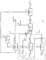
- FIG. 1 A process for producing Syngas from a flue gas stream and a CO 2 -containing natural gas stream which embodies various features of the present invention is shown in Figure 1 as a schematic flow sheet.
- the illustrated system would receive a flue gas stream 1 from some combustor of fossil fuel, such as coal, oil or natural gas, or from diesel or gasoline engines or the like; such might in many instances be a flue gas stream from a power plant for the production of electrical power which would have a fairly constant output.
- a flue gas stream from a boiler-operated power plant or from a kiln or the like, fueled by air-oxidation would include a major portion of nitrogen together with CO 2 , nitrogen oxides (NOx), sulfur oxides (SOx) and other minor gaseous components.
- NOx nitrogen oxides
- SOx sulfur oxides
- Such flue gas steam which would otherwise be likely vented to the atmosphere, is used as a carbon dioxide source in the present process.
- the stream 1 is fed at appropriate temperature and pressure to a first membrane separation device 2, which is depicted in the lower left hand region of Figure 1 .
- a first membrane separation device 2 For carbon dioxide separation from flue gas, containing a major portion of nitrogen, various membrane separation systems may be employed; membranes are preferably chosen that would exhibit a preference for CO 2 over N 2 of at least about 5 to 1 and more preferably, at least about 10 to 1.
- Polydimethyl silicone (PDMS) membranes may be particularly preferred, and such membranes can be provided in various thicknesses, for example between about 0.1 micron and 10 microns.
- porous polymeric supportive layer ofpolysulfone, polyethylene, PVC, cellulose nitrate and the like, e.g. polysulfone UF membranes, or other porous materials such as etched metals and ceramics, e.g. etched aluminum.
- the first membrane device 2 may include 1-3 stages and ultimately creates two streams, a permeate stream 4 that comprises predominantly carbon dioxide, with minor amounts of NOx, SOx and a tolerable amount of N 2 , and a concentrate stream 3.
- the concentrate stream 3 comprises predominantly nitrogen with some residual amounts of primarily CO 2 , NOx, and SOx, usually at least about 80 volume percent N 2 .
- This stream 3 can be vented to the atmosphere, treated or otherwise disposed of according to available methods.
- the permeate stream 4 containing predominantly carbon dioxide, e.g. at least about 60 volume percent, preferably at least about 70%, more preferably at least about 80% and most preferably at least about 90%, is directed to a flow regulator/blender 6.
- the other incoming stream is a stream 11 of natural gas containing primarily carbon dioxide and methane.
- it may contain between about 3% to 35% CO 2 or between about 2% to 40% CO 2 , with the remainder being substantially all methane.
- This stream 11 is delivered to a second membrane separation device 12, which also produces a concentrate stream 13 and a permeate stream 14.
- the second membrane device 12 may also include multiple stages of membrane separation. It also can use various different gas separation membranes as known in this art; the membranes chosen should have a preference for CO 2 over CH 4 of at least about 2 to 1 and preferably at least about 4 to 1.
- Polymeric membranes such as those of the classes mentioned hereinbefore, are preferred, and most preferred are PDMS membranes.
- the primarily methane natural gas inflow stream 11 is exposed in the second membrane separation device 12 to a polymeric semipermeable membrane that is selective for CO 2 in preference to CH 4 .
- the device When treating an inflow that contains a major amount of CH 4 , the device produces a permeate stream that has an increased amount of CO 2 (relative to the inflow natural gas stream 11) and that contains carbon dioxide and methane at a mole ratio not more than a 50% excess of either component.
- an excess of carbon dioxide may be desired, while for others, a methane excess may be desired.
- the permeate stream may also contain tolerable small amounts of other gases such as nitrogen, usually not more than about 10 volume % and preferably not more than about 5%.
- the permeate stream 14 having the desired mole ratio of CO 2 and methane is delivered as one feedstream to a plasma reformer 15 to be discussed hereinafter.
- the concentrate stream 13 from the second membrane separation device 12 is predominantly methane, usually about 90 to 99 volume %, preferably at least about 96% and more preferably at least about 98%, with the remainder primarily CO 2 . It is directed to a flow regulator 25 that splits the stream 13 into 3 substreams under the control of a control system 100.
- a first substream 26 from the flow regulator 25 is directed to the blending regulator 6 where it is mixed with the predominantly CO 2 stream 4 exiting the first membrane separation device so as to produce a blended stream 27 that is directed as another feedstream to the plasma reformer 15 where it is mixed with the permeate stream 14.
- the blending at the regulator 6 is such that the carbon dioxide and methane mole ratio is likewise not more than a 50% excess of either.
- a second substream 28 is fed to a combustor-generator 20, such as an internal combustion engine or a turbine which drives an attached electrical generator, to generate electrical power by burning methane with air, which results in the creation of carbon dioxide and water vapor.
- the exhaust gas stream 29 from the combustor-generator 20 is directed to a third membrane separation device 30 which may have characteristics similar to the first membrane separation device 2.
- the device 30 produces a permeate stream 32 that is predominantly CO 2 with tolerable concentrations of NOx, SOx, and N 2 .
- the concentrate stream 31, comprising predominantly nitrogen, is handled in the same manner as the concentrate stream 3, i.e. by exhaust to the atmosphere or further treatment.
- the predominantly CO 2 permeate stream 32 is fed to another regulator/blender 33 to which the third substream 32a from the regulator 25 is also delivered.
- the regulator-blender 33 mixes the streams 32 and 32a to produce yet another feedstream 34 for delivery to the reformer wherein carbon dioxide is again present in a mole ratio to methane of between 0.67 to 1 and 1.5 to 1.
- This blended feedstream 34 is mixed along with the feedstreams 14 and 27 to provide a composite feedstream that is delivered to the plasma reformer 15.
- the composite feedstream contains CO 2 and CH 4 in about equal mole amounts or at a ratio where one does not exceed the other by more than 50%; this mole ratio is loosely referred to herein as an about 50/50 ratio.
- the control system 100 regulates the overall process by controlling the compositions and the various flow rates so that the composite feedstream has the desired composition for the plasma reformer 15, e.g. equal moles of CO 2 and CH 4 or usually within about 2-5% of equal. However, if desired for a particular reformation process, a 20% or 30% or higher molar amount of either CO 2 or CH 4 might be present in a particular composite feedstream.
- a composite feedstream of desired composition is fed to the plasma reformer by the control system 100.
- blender/regulators 6,33 might each be connected to a separate channel of a gas chromatograph (GC) with interface to a computer control system 100, so as to control the amounts of CH 4 and CO 2 , exiting the regulators via a hydraulic or pneumatic valve system that is also associated with the regulator 25 and an inlet valve in the incoming natural gas line 11.
- GC gas chromatograph
- the membrane separation devices may be connected to other channels of the GC and appropriately controlled by operation of multiple stages and/or recycling therewithin. Instructions and overall control are programmed into a CPU associated with the main control system 100.
- the plasma reformer 15 can utilize the plasma technology that has emerged in the last decade as an efficient process for the conversion of carbon dioxide, in a gaseous mixture containing a source of hydrogen, to produce Syngas (a mixture of hydrogen and carbon monoxide). Methane and/or water are commonly used as a hydrogen source.
- plasma reformers are used, and more particularly plasma reformers that rely on microwave energy to create the plasma as they are capable of operation at relatively low energy cost and can be operated as a continuous flow process through the reactor.
- microwave type plasma reactors are shown in U.S. Patents Nos. 5,266,175 and 5,277,773 , and as known in this art, plasma reactors of this type can be used to produce Syngas from gas feed streams containing CO 2 and methane in the previously stated about 50/50 mole ratio.
- Such a microwave energy plasma reformer 15 can be supplied with sufficient electrical power from the combustor-generator 20 as indicated in the flow sheet by the schematic distribution line 22.
- the electrical power generated can be used to drive the auxiliary blowers, compressors and other machinery to operate the three membrane separation devices 2, 12 and 30. It is expected that all of this can be accomplished without requiring power from a power plant that may be supplying the flue gas stream 1. This may be important because the combustor supplying the flue gas stream 1 may be a non-electrical power generator, such as a kiln, a steel mill or some other heat-generating device.
- the output from the plasma reformer 15 is a continuous stream of Syngas comprising a mixture of primarily carbon monoxide and hydrogen.
- the output ratio will vary slightly depending upon the precise ratio of the about 50/50 mixture of the feed streams being supplied to the plasma reformer. If a higher mole ratio of carbon dioxide is present in the combined feed streams, then the Syngas may include a greater percentage of CO and a smaller percentage of hydrogen.
- the control system 100 is utilized to control and regulate the flow regulator/blenders 6 and 33, the regulator 25 and the inflow of natural gas in the line 11 while monitoring the compositions and flow rates of the three feedstreams so that the overall system operates continuously to provide a composite feedstream within the desired mole ratio.
- the process efficiently tracks the flue gas inflow to fully utilize it as its primary CO 2 source, making adjustments as needed to present three feedstreams that are mixed to provide a composite feedstream of desired character that is fed to the plasma reformer 15.
- Syngas Although there are various uses for Syngas as well known in this art, the process described above can be advantageously coupled with a Fischer-Tropsch (F-T) reactor that will generate synthetic liquid hydrocarbons from a Syngas feedstock of this character, which synthetic hydrocarbon mixtures are sometimes referred to as Synfuels.
- F-T Fischer-Tropsch
- Figure 2 Depicted in Figure 2 is a further process embodying various features of the present invention which incorporates an F-T reactor 40 as a final stage in such an overall process. The primary portion of the process is carried out as described just above with respect to Figure 1 .
- the exit stream 16 of Syngas is delivered to an F-T reactor 40.
- An F-T reactor or F-T synthesis utilizes a known set of chemical reactions that effectively convert a mixture of carbon monoxide and hydrogen into liquid hydrocarbons.
- the F-T synthesis has become a key component of gas-to-liquid fuel technology and produces a petroleum substitute.
- the desirable products from the F-T synthesis are primarily alkenes and/or alkanes.
- the F-T reactions are generally carried about at temperatures between about 150° and 300° C and at relatively high pressures.
- Fischer-Tropsch reactors are well-known, and examples are described in the U.S. patents mentioned hereinbefore.
- the compressors needed to provide the required pressure can be supplied with electrical power from the combustor-generator 20; many of the chemical reactions, once operating, are exothermic and provide heat and some carbon dioxide. Moreover, an otherwise troublesome by-product of F-T, i.e. carbon dioxide, can be used to advantage when incorporated into such a process such as that of Fig. 1 .
- the F-T reactor byproducts including heat and CO 2 , as well as any unreacted H 2 , CH 4 and/or CO, are schematically depicted by the line 45 indicating that they are being recycled to the combustor-generator 20 where they are effectively used to provide additional combustibles, additional CO 2 for delivery through the line 29 to the third membrane separation device, and heat for use in conjunction with a gas turbine generator or the like to produce additional electrical power.
- control system 100 assures that efficient continuous operation is afforded as explained above.
- the control system 100 monitors the amount of methane being separated as the concentrate stream 13 and splits the stream into the three substreams at the regulator 25.
- a sufficient amount of natural gas is caused to be supplied through the line 11 to the second membrane device 12 so that the concentrate stream 13 will be sufficient to provide sufficient methane to fulfill the desired functions of the substreams 26, 28 and 32a.
- sufficient methane is supplied to the line 26 to blend with all of the CO 2 being obtained from the flue gas stream 1 to provide the feedstream 27 of desired composition which is then mixed with the feedstream 14 that permeates through the membrane separation device 12.
- control system 100 assures that sufficient methane is delivered through the lines 28 and 32a to generate the desired amount of electric power while providing a CO 2 -containing exhaust stream 29, which will be separated in the third membrane separation device 30 to create the predominantly CO 2 stream 32.
- the third substream 32a is controlled to provide sufficient methane flow to mix in the desired about 50/50 mole mixture with the stream 32 in the regulator/blender 33.
- the result of this overall process control is such as to feed a composite feedstream of desired composition to the plasma reformer, e.g. within about 2% of a 1:1 ratio of CO 2 and CH 4 .
- FIG. 3 Illustrated in Figure 3 is a further embodiment of a process for producing Syngas from a CO 2 -containing natural gas stream that embodies various features of the invention.
- the Figure 3 embodiment differs from the previously described processes in that it is operated in a location where there is no ready flow of a flue gas stream from a fossil fuel combustor or the like.
- the incoming natural gas stream 11 that contains between about 2% and about 40% carbon dioxide, with the remainder mainly methane, and is similarly delivered to a membrane separation device 12.
- the device 12 separates the inflow to a greater than 90% methane concentrate stream 13 and a permeate stream 14 that contains an increased percentage of CO 2 wherein the composition of CO 2 and methane is in an about 50/50 mole ratio.
- the permeate stream 14 is delivered to a transformation device, preferably a microwave plasma reformer 15.
- the predominantly methane concentrate stream 13 is delivered to a regulator 25 which again divides the total flow of the stream 13 into three substreams 26, 28 and 32a.
- the control system 100 is used to regulate the splitting and produce the desired three separate flows, or three substreams, at the regulator 25. Sufficient methane is included in the substream 28 to create at least adequate electrical power to run the plasma reformer 15 and the auxiliary power needed for the two membrane separation operations 12 and 30. As previously, the control system 100 would monitor the amount of CO 2 flowing in the line 32 and supply sufficient methane in the line 32a so that the regulator/blender 33 would create the desired blend of an about 50/50 mole ratio of CO 2 and methane to be delivered through the line 34 to the plasma reformer 15.
- the membrane separation device 12 When it is desired to create a substream 26 suitable for exportation to natural gas users, it may be desirable to operate the membrane separation device 12 to produce a concentrate of methane containing a relatively small amount of CO 2 , e.g. about 2% or less. Alternatively, the substream 26 could be subjected to a further membrane separation step and the CO 2 that is removed added to the stream 32.
- the control system 100 would, as described generally with respect to Figures 1 and 2 , control the overall process to ultimately produce a mixture of the two feedstreams 14 and 34 that would have the desired mole ratio, e.g. about 1:1 with no more than a 2% excess of CO 2 .
- Syngas is produced as a stand-alone operation while also providing (1) a methane stream of pipeline quality e.g. about 2% or less CO 2 for export and (2) excess electrical power as desired at a particular installation, i.e. above that needed to meet current requirements of the overall process.
- a methane stream of pipeline quality e.g. about 2% or less CO 2 for export
- excess electrical power as desired at a particular installation, i.e. above that needed to meet current requirements of the overall process.
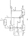
- Figure 4 shows a further embodiment of a process for producing Syngas from a CO 2 -containing natural gas stream, which embodies various features of the invention and has similarity to the process illustrated in Figure 3 .
- the incoming natural gas stream 11 would be one that contains between about 2 and about 40% carbon dioxide with the remainder being essentially methane. It is similarly delivered to a membrane separation device 12 which would separate it into a concentrate stream 13 containing predominantly methane and a permeate stream 14 that would contain carbon dioxide and methane in an about 50/50 mole ratio, for example, about 1 mole of CO 2 to 0.9 mole of methane.
- the permeate stream again serves as a first feedstream for a microwave plasma reformer 15 or the like, and the predominantly methane concentrate stream 13 is delivered to a regulator 25 which again divides the total flow of the stream 13 into three substreams 26, 28 and 32a.
- the substream 28, as before, is directed to a combustor/generator 20, and the substream 32a is routed to the regulator/blender 33 where it is blended with the predominantly CO 2 stream 32 from the membrane separation device 30 as before.
- the substream 26 is delivered to a second plasma reformer 115 where it is mixed with a separate incoming stream of water/steam 114 that is being supplied.
- the plasma reformer 115 may operate on the principles set forth in the '773 patent, and it will produce a Syngas having a higher hydrogen content than that of the plasma reformer 15 as a result of using the methane-rich stream 26 and water and/or steam.
- the ratio of hydrogen to carbon monoxide may be about 1:1 in the Syngas produced by the plasma reformer 15, whereas by adjustment of the flows of the stream 26 and the incoming stream 114 of water and/or stream, the plasma reformer 115 may produce a ratio of as much as about 3 to 1 hydrogen to carbon monoxide in the Syngas stream 116.
- Syngas stream 116 can be diverted via a flow splitter 124, to a Water Shift Reactor (WSR) 120, in which CO in the diverted portion 117 reacts with another inflow stream of water and/or steam 118, to produce CO 2 and H 2 via the reaction CO + H 2 O ⁇ CO 2 + H 2 ; this further increases the amount of hydrogen produced. It is then possible to separate a CO 2 -rich stream 121 and a hydrogen-rich stream 122, using for example a PSA (pressure swing adsorption) unit 123, as known in this art.
- PSA pressure swing adsorption
- the CO 2 -rich stream is then fed to the regulator/blender 33 where it is combined with the methane rich stream 32a and the predominantly CO 2 stream 32 to form the feedstream 34 for the first plasma reformer 15.
- the hydrogen-rich stream 122 is combined with the Syngas streams 16 and 119, which further increases the hydrogen content in the ultimate Syngas stream 130.
- An installation is operated according to the flowsheet depicted in Figure 3 to process a natural gas source 11 containing about 10 vol% carbon dioxide and about 90 vol% methane.
- the natural gas is treated using the membrane separation devices and a microwave plasma reactor to produce Syngas, to produce a variable amount of pipeline quality gas for export from the methane rich product stream 13, and to produce excess electrical power for export over and above that needed to operate the overall installation.
- a combustor-generator 20 is used to convert some of the methane into carbon dioxide for use in the plasma reformer 15 while, at the same time, also producing the electrical power required to operate the plasma reformer.
- a portion of the methane rich stream 32a is fed directly to the blender/regulator 33 to match the amount of CO 2 being supplied from the second membrane system 30 which is producing a predominantly CO 2 stream 32 from the exhaust gas stream from the combustor-generator 20.
- Operation is carried out in accordance with the flowsheet depicted in Figure 3 , with an inflow stream 11 of about 1000 cubic meters per hour at standard temperature and pressure (Nm 3 /hr) of natural gas into the membrane separation device 12.
- the device 12 is designed to produce a permeate stream 14 containing a suitable ratio of CO 2 /CH 4 that will serve as a first feedstream for delivery to the plasma reformer, plus a methane rich concentrate stream 13 which contains minimal CO 2 , preferably not greater than about 2% CO 2 , such as is considered to be pipeline grade natural gas.
- a permeate stream flow is produced of about 152 Nm 3 /hr with a composition of about 54.5% CO 2 and about 45.5 % CH 4 .
- the methane rich stream 13 flow is about 848 Nm 3 /hr comprising about 98% CH 4 and 2 % CO 2 .
- the control system 100 then adjusts the flow regulator 25 so that the flow rate of methane rich stream 32a (produced from the membrane separation device 12) is sufficient to balance the predominantly CO 2 stream 32 coming from the second membrane separation device 30 to create a desired blend; its composition should be such that, when this feedstream 34 is combined with the permeate stream 14, a composite feedstream having the desired CO 2 /CH 4 mole ratio, i.e. about 1:1, is created to feed the plasma reformer 15.
- the remainder of the methane rich stream is burned in the combustor to produce electric power which is sufficient to operate the plasma reformer 15 and the other parts of the installation, e.g. the membrane separation steps, and excess power is exported off-site.
- a total of about 1591 kW of power is generated by the combustor, assuming 40% efficiency in the electricity generation, which is considerably more than needed to operate the plasma reformer 15.
- the exhaust gas from the combustor-generator 20 is treated in a second membrane system 30 to produce a predominantly CO 2 stream 32 containing approximately 400 Nm 3 /hr CO 2 (assuming about 98% recovery) which is then fed to the blender/regulator 33 where it is mixed with the stream 32a.
- the total amount of CO 2 in the composite feedstream delivered to the plasma reformer is about 500 Nm 3 /hr; it is made up predominately of CO 2 in the permeate stream 14 plus the predominantly CO 2 stream 32.
- about 440 Nm 3 /hr of the methane rich stream is sent as the stream 32a to blend with the predominantly CO 2 stream 32, which has a flow of about 400 Nm 3 /hr of CO 2 .
- the control system 100 monitors the stream compositions and makes adjustments as needed.
- the total Syngas produced is about 2000 Nm 3 /hr assuming 100% conversion, and it requires about 300 kW of power to operate the plasma reformer 15, assuming a power consumption of 0.15 kWh/m 3 Syngas.
- there is an excess power production of about 1291 kW which can be used to operate other parts of the process plant, e.g. to power the membrane separation systems etc., and the remainder of the power can be exported off-site.
- the methane rich substream 26 may be exported as pipeline quality gas for 1000 Nm 3 /hr of inflow natural gas as above.
- the methane rich stream 26 is burned in the combustor, and about 100 Nm 3 /hr of the CO 2 produced is captured; this produces about 398 kW of power from the combustor-generator.
- the total flow of CO 2 in the composite feedstream being fed to the plasma reformer is only 185 Nm 3 /hr, which is made up of the CO 2 in the permeate stream 14 and the predominantly CO 2 stream 32.
- the process is able to utilize substantially the entire CO 2 content of the inflow natural gas stream, as well as that produced by burning some of the methane in order to supply all the energy required for the production of Syngas in a plasma reformer which uses methane and carbon dioxide as the only reactants.
- the net CO 2 emitted from the process is essentially zero, assuming it is all converted to Syngas in the plasma reformer, or at the very least, CO 2 emissions will be significantly reduced compared to conventional gas to liquid technology where all the CO 2 is emitted to atmosphere.
Landscapes
- Chemical & Material Sciences (AREA)
- Chemical Kinetics & Catalysis (AREA)
- Organic Chemistry (AREA)
- Engineering & Computer Science (AREA)
- General Health & Medical Sciences (AREA)
- Health & Medical Sciences (AREA)
- Inorganic Chemistry (AREA)
- Combustion & Propulsion (AREA)
- Oil, Petroleum & Natural Gas (AREA)
- General Chemical & Material Sciences (AREA)
- Electromagnetism (AREA)
- Mechanical Engineering (AREA)
- Toxicology (AREA)
- Physics & Mathematics (AREA)
- Analytical Chemistry (AREA)
- Separation Using Semi-Permeable Membranes (AREA)
- Carbon And Carbon Compounds (AREA)
- Production Of Liquid Hydrocarbon Mixture For Refining Petroleum (AREA)
- Hydrogen, Water And Hydrids (AREA)
Claims (15)
- Verfahren zur Produktion von Synthesegas in einem Plasmareaktor aus einem Erdgasstrom (11), der eine signifikante Menge CO2 enthält, wobei das Verfahren Folgendes umfasst:Bereitstellen eines Erdgasstroms (11), der CH4 und zwischen etwa 2 und 40 Volumen-% CO2 enthält, und Behandeln eines derartigen Stroms in einer Vorrichtung mit semipermeabler Membran (12) zum Bereitstellen eines ersten Permeatstroms (14), der einen erhöhten CO2-Gehalt aufweist und CO2 und CH4 in einem Molverhältnis von etwa 50/50 enthält, zur Verwendung als ein erster Einsatzstrom und zum Bereitstellen eines methanreichen Konzentratstroms (13), der mindestens etwa 90 Volumen-% Methan enthält,Verbrennen eines Teilstroms (28) des Konzentratstroms (13) mit Luft in einer Cogenerationsapparatur (20) zur Erzeugung von elektrischer Leistung,Zuführen eines Abgasstroms (29) aus der Cogenerationsapparatur (20) zu einer anderen Vorrichtung mit semipermeabler Membran (30) und Abtrennen eines überwiegend CO2 enthaltenden Permeatstroms (32),Mischen des überwiegend CO2 enthaltenden Permeatstroms (32) mit einem zweiten Teilstrom (32a) des methanreichen Konzentratstroms (13) zur Erzeugung eines zweiten Einsatzstroms (34), der CO2 und CH4 in einem Molverhältnis von etwa 50/50 enthält,Zuführen eines zusammengesetzten Einsatzstroms aus dem ersten Einsatzstrom und dem zweiten Einsatzstrom (34), der CO2 und CH4 in einem Molverhältnis von etwa 1:1 mit einem CO2-Überschuss von höchstens 2% enthält, zu einem Mikrowellenplasmareaktor (15), der das CO2 und Methan in einen Strom von Synthesegas (16) umwandelt,wodurch Synthesegas in einem umweltfreundlichen Verfahren aus CO2 enthaltendem Erdgas produziert wird, wobei das Gesamtverfahren so gesteuert wird, dass genug elektrische Leistung zum Betreiben der Membrantrennvorrichtungen (12, 30) und des Plasmareaktors (15) erzeugt wird.
- Verfahren nach Anspruch 1, bei dem der Strom von Synthesegas als Einsatzstoff für einen Fischer-Tropsch-Reaktor (F-T-Reaktor), der flüssige Kohlenwasserstoffe, Wärme und Restgase erzeugt, bereitgestellt wird.
- Verfahren nach Anspruch 2, bei dem Wärme aus dem F-T-Reaktor zur Erzeugung von elektrischer Leistung in der Cogenerationsapparatur verwendet wird und die Restgase in der Cogenerationsapparatur verbrannt oder mit dem Abgasstrom oder einem Rauchgasstrom (1) zur Bereitstellung von zusätzlichem Kohlendioxid vereinigt werden.
- Verfahren nach einem der Ansprüche 1-3, bei dem in den Vorrichtungen mit semipermeabler Membran (12, 30) Polymermembranen aus der Gruppe bestehend aus Polydimethylsilikon (PDMS), Polyimiden, Polyarylethern, Polyarylketonen, Polycarbonaten, Polysulfonen und Polyacetylenen eingesetzt werden.
- Verfahren nach einem der Ansprüche 1-3, bei dem in den Vorrichtungen mit semipermeabler Membran (12, 30) Flächenmaterial aus Polydimethylsilikon (PDMS) als Laminat mit einer tragenden porösen Polymermembran eingesetzt wird.
- Verfahren nach Anspruch 1, bei dem der Erdgasstrom (11) zwischen etwa 5 Volumen-% und 35 Volumen-% CO2 enthält, der methanreiche Konzentratstrom (13) mindestens etwa 98 Volumen-% Methan umfasst und ein dritter Teilstrom (26) aus dem methanreichen Konzentratstrom (13) abgezweigt und als Erdgas mit Pipeline-Qualität exportiert wird.
- Verfahren nach Anspruch 1, das Folgendes einschließt:Abzweigen eines dritten Teilstroms (26) aus dem Konzentratstrom (13) und Zuführen eines derartigen Teilstroms zu einer zweiten Mikrowellenplasma-Reformierungsvorrichtung (115) als Mischung mit Dampf und/oder Wasser (114) zum Umwandeln einer derartigen Mischung in einen zweiten Synthesegas-Produktstrom mit höherem Wasserstoffgehalt als der erste Strom von Synthesegas (16) undVereinigen des ersten und zweiten Synthesegas-Produktstroms, wobei das Verfahren so gesteuert wird, dass genug elektrische Leistung zum Betreiben der Membrantrennvorrichtungen (12, 20) und beider Plasma-Reformierungsvorrichtungen erzeugt wird.
- Verfahren nach Anspruch 7, bei dem ein Teil des zweiten Synthesegas-Produktstroms einem Konvertierungsreaktor (Water Shift Reactor, WSR) zugeführt wird, in dem dessen CO-Fraktion mit Wasser und/oder Dampf zur Produktion von zusätzlichem H2 umgesetzt wird, und H2 aus dem WSR als wasserstoffreicher Strom mit dem ersten Synthesegas-Produktstrom und dem Rest des zweiten Synthesegas-Produktstroms vereinigt wird.
- Verfahren nach Anspruch 8, bei dem der Austrag aus dem WSR einer Druckwechseladsorptionseinheit zur Produktion des wasserstoffreichen Stroms und eines CO2-reichen Stroms, der zu dem überwiegend CO2 enthaltenden Permeatstrom gegeben wird, zugeführt wird.
- Verfahren nach Anspruch 1, das Folgendes einschließt:Bereitstellen eines Rauchgasstroms (1) aus einer Kohlenstoff- oder Kohlenwasserstoff-Verbrennungsvorrichtung und Trennen eines derartigen Stroms in einer weiteren Vorrichtung mit semipermeabler Membran (2) in einen anderen überwiegend CO2 enthaltenden Strom (4) und einen zweiten Strom (3), der überwiegend N2 enthält,Mischen eines dritten Teilstroms (26) aus dem methanreichen Konzentratstrom (13) mit dem anderen überwiegend CO2 enthaltenden Strom (4) zur Erzeugung eines dritten Einsatzstroms (27), der CO2 und CH4 in einem Molverhältnis von etwa 50/50 enthält, undEinarbeiten des dritten Einsatzstroms (27) in dem zusammengesetzten Einsatzstrom.
- Verfahren nach Anspruch 10, bei dem der Strom von Synthesegas als Einsatzstoff für einen Fischer-Tropsch-Reaktor (F-T-Reaktor), der flüssige Kohlenwasserstoffe, Wärme und Restgase erzeugt, bereitgestellt wird.
- Verfahren nach Anspruch 11, bei dem Wärme aus dem F-T-Reaktor zur Erzeugung von elektrischer Leistung in der Cogenerationsapparatur verwendet wird und die Restgase in der Cogenerationsapparatur (20) verbrannt oder mit dem Abgasstrom oder einem Rauchgasstrom (1) zur Bereitstellung von zusätzlichem Kohlendioxid vereinigt werden.
- Verfahren nach einem der Ansprüche 10-12, bei dem in der weiteren Vorrichtung mit semipermeabler Membran (2) eine Polymermembran aus der Gruppe bestehend aus Polydimethylsilikon (PDMS), Polyimiden, Polyarylethern, Polyarylketonen, Polycarbonaten, Polysulfonen und Polyacetylenen eingesetzt wird.
- Verfahren nach Anspruch 13, bei dem die weitere semipermeable Membran PDMS-Flächenmaterial mit einer Dicke zwischen etwa 0,1 Mikron und 10 Mikron umfasst.
- Verfahren nach Anspruch 13 oder 14, bei dem es sich bei der weiteren semipermeablen Membran um Polydimethylsilikon-Flächenmaterial als Laminat mit einer tragenden porösen Polymermembran handelt.
Applications Claiming Priority (2)
| Application Number | Priority Date | Filing Date | Title |
|---|---|---|---|
| US36297510P | 2010-07-09 | 2010-07-09 | |
| PCT/US2011/042365 WO2012006155A1 (en) | 2010-07-09 | 2011-06-29 | Syngas production through the use of membrane technologies |
Publications (2)
| Publication Number | Publication Date |
|---|---|
| EP2590894A1 EP2590894A1 (de) | 2013-05-15 |
| EP2590894B1 true EP2590894B1 (de) | 2016-03-23 |
Family
ID=44474975
Family Applications (1)
| Application Number | Title | Priority Date | Filing Date |
|---|---|---|---|
| EP11734202.2A Not-in-force EP2590894B1 (de) | 2010-07-09 | 2011-06-29 | Syngasproduktion anhand des einsatzes von membrantechnologien |
Country Status (9)
| Country | Link |
|---|---|
| US (1) | US8669294B2 (de) |
| EP (1) | EP2590894B1 (de) |
| JP (1) | JP5799094B2 (de) |
| CN (1) | CN103108831B (de) |
| AU (1) | AU2011276451B2 (de) |
| CA (1) | CA2804389C (de) |
| TW (1) | TWI460122B (de) |
| WO (1) | WO2012006155A1 (de) |
| ZA (1) | ZA201300052B (de) |
Families Citing this family (48)
| Publication number | Priority date | Publication date | Assignee | Title |
|---|---|---|---|---|
| US9856769B2 (en) | 2010-09-13 | 2018-01-02 | Membrane Technology And Research, Inc. | Gas separation process using membranes with permeate sweep to remove CO2 from combustion exhaust |
| US9140186B2 (en) * | 2010-09-13 | 2015-09-22 | Membrane Technology And Research, Inc | Sweep-based membrane gas separation integrated with gas-fired power production and CO2 recovery |
| US9005335B2 (en) * | 2010-09-13 | 2015-04-14 | Membrane Technology And Research, Inc. | Hybrid parallel / serial process for carbon dioxide capture from combustion exhaust gas using a sweep-based membrane separation step |
| CN103058136B (zh) * | 2012-11-28 | 2015-06-03 | 吉林大学 | 车载燃料的微波等离子在线制氢系统 |
| DE102012023832A1 (de) * | 2012-12-06 | 2014-06-12 | Evonik Industries Ag | Integrierte Anlage und Verfahren zum flexiblen Einsatz von Strom |
| EP2961684A2 (de) * | 2013-02-28 | 2016-01-06 | Air Products and Chemicals, Inc. | Verfahren und vorrichtung zur erzeugung von sauerstoff und stickstoff mittels ionentransportmembranen |
| BR112015027126A2 (pt) * | 2013-05-10 | 2018-04-24 | Shig Kim Gwan | aparelho para a separação de dióxido de carbono, membrana de separação de dióxido de carbono, e método para separar dióxido de carbono de um gás de subproduto. |
| US9533260B2 (en) * | 2013-07-03 | 2017-01-03 | Centro De Investigacion En Quimica Aplicada | Method and system for obtaining sweet gas, synthetic gas and sulphur from natural gas |
| DE102013016660A1 (de) | 2013-10-09 | 2015-04-09 | Ralf Spitzl | Verfahren und Vorrichtung zur plasmakatalytischen Umsetzung von Stoffen |
| DE102013020905A1 (de) * | 2013-12-16 | 2015-06-18 | Ralf Spitzl | Verfahren und Vorrichtungen zur Herstellung von Synthesegas |
| US11939477B2 (en) | 2014-01-30 | 2024-03-26 | Monolith Materials, Inc. | High temperature heat integration method of making carbon black |
| US10370539B2 (en) | 2014-01-30 | 2019-08-06 | Monolith Materials, Inc. | System for high temperature chemical processing |
| US20150211378A1 (en) * | 2014-01-30 | 2015-07-30 | Boxer Industries, Inc. | Integration of plasma and hydrogen process with combined cycle power plant, simple cycle power plant and steam reformers |
| BR112016017429B1 (pt) | 2014-01-31 | 2022-10-04 | Monolith Materials, Inc | Maçarico de plasma |
| US10060348B2 (en) * | 2014-09-25 | 2018-08-28 | Air Products And Chemicals, Inc. | Membrane separation of carbon dioxide from natural gas with energy recovery |
| WO2016053182A1 (en) * | 2014-09-30 | 2016-04-07 | National University Of Singapore | Catalytic membrane system for converting biomass to hydrogen |
| CA2975723C (en) | 2015-02-03 | 2023-08-22 | Monolith Materials, Inc. | Regenerative cooling method and apparatus |
| JP2018510231A (ja) | 2015-02-03 | 2018-04-12 | モノリス マテリアルズ インコーポレイテッド | カーボンブラック生成システム |
| WO2017019683A1 (en) | 2015-07-29 | 2017-02-02 | Monolith Materials, Inc. | Dc plasma torch electrical power design method and apparatus |
| WO2017027385A1 (en) | 2015-08-07 | 2017-02-16 | Monolith Materials, Inc. | Method of making carbon black |
| WO2017044594A1 (en) | 2015-09-09 | 2017-03-16 | Monolith Materials, Inc. | Circular few layer graphene |
| DE102015218098A1 (de) * | 2015-09-21 | 2017-03-23 | Deutsche Lufthansa Ag | Verfahren zur thermischen Spaltung von Kohlenwasserstoffen und korrespondierende Vorrichtung |
| CN105688618B (zh) * | 2016-01-19 | 2018-12-11 | 桂盟链条(太仓)有限公司 | 一种热处理废气电浆重组发电方法及电浆重组反应器 |
| WO2017190015A1 (en) | 2016-04-29 | 2017-11-02 | Monolith Materials, Inc. | Torch stinger method and apparatus |
| US10787362B2 (en) * | 2016-05-16 | 2020-09-29 | Christopher L. de Graffenried, SR. | Hydrogen co-firing with carbon pre-capture for higher carbon ratio fossil fuels |
| US9546785B1 (en) * | 2016-06-13 | 2017-01-17 | Membrane Technology And Research, Inc. | Sweep-based membrane separation process for removing carbon dioxide from exhaust gases generated by multiple combustion sources |
| CN106281519B (zh) * | 2016-10-21 | 2021-09-14 | 山西高碳能源低碳化利用研究设计院有限公司 | 带有膜分离器的焦炉煤气甲烷化装置和方法 |
| US9782718B1 (en) | 2016-11-16 | 2017-10-10 | Membrane Technology And Research, Inc. | Integrated gas separation-turbine CO2 capture processes |
| CA3055830A1 (en) | 2017-03-08 | 2018-09-13 | Monolith Materials, Inc. | Systems and methods of making carbon particles with thermal transfer gas |
| CN115637064A (zh) | 2017-04-20 | 2023-01-24 | 巨石材料公司 | 颗粒系统和方法 |
| US10654582B2 (en) * | 2017-08-09 | 2020-05-19 | Hamilton Sundstrand Corporation | Fuel separation unit for inert gas generating system |
| EP3676335A4 (de) | 2017-08-28 | 2021-03-31 | Monolith Materials, Inc. | Teilchensysteme und verfahren |
| WO2019046320A1 (en) | 2017-08-28 | 2019-03-07 | Monolith Materials, Inc. | SYSTEMS AND METHODS FOR GENERATING PARTICLES |
| CN108251284B (zh) * | 2017-12-19 | 2021-02-26 | 环境保护部华南环境科学研究所 | 一种微生物硝化法分解固体有机物废弃物的设备 |
| CN112867702B (zh) | 2018-08-23 | 2024-07-26 | 转化材料有限公司 | 处理气体的系统和方法 |
| US11633710B2 (en) | 2018-08-23 | 2023-04-25 | Transform Materials Llc | Systems and methods for processing gases |
| US11155760B2 (en) * | 2019-04-30 | 2021-10-26 | Honeywell International Inc. | Process for natural gas production |
| EP4034288B1 (de) * | 2019-09-25 | 2025-12-31 | Shell Internationale Research Maatschappij B.V. | Verfahren zur reduzierung von injektorablagerungen |
| JP7700110B2 (ja) * | 2020-05-14 | 2025-06-30 | 日東電工株式会社 | 二酸化炭素捕捉処理システム及びco2ネガティブエミッション工場 |
| WO2022010346A1 (en) * | 2020-07-10 | 2022-01-13 | Technische Universiteit Eindhoven | Plasma assisted direct co2 capture and activation |
| CN115956061A (zh) * | 2020-08-21 | 2023-04-11 | 托普索公司 | 电加热重整设备中的尾气利用 |
| CA3097513C (en) * | 2020-10-30 | 2024-01-16 | Thermon Canada Inc. | Methane destruction apparatus and method of converting fugitive methane emissions |
| CA3203126A1 (en) * | 2021-01-08 | 2022-07-14 | Shekhar TEWARI | Enhanced hydrogen recovery utilizing gas separation membranes integrated with pressure swing adsorption unit and/or cryogenic separation system |
| CN116917447A (zh) * | 2021-03-31 | 2023-10-20 | 古河电气工业株式会社 | 有用烃的制造方法及有用烃的制造装置 |
| WO2023039043A1 (en) * | 2021-09-09 | 2023-03-16 | Transform Materials Llc | Systems and methods for processing gases |
| AU2023206393A1 (en) * | 2022-01-14 | 2024-08-22 | Recarbon, Inc. | Integrated carbon transformation reformer and processes |
| WO2024254496A2 (en) | 2023-06-07 | 2024-12-12 | Alchemy Co2, Pbc | Systems and methods of renewable natural gas processing |
| WO2024254503A2 (en) | 2023-06-07 | 2024-12-12 | Alchemy Co2, Pbc | Systems and methods of renewable natural gas processing |
Citations (1)
| Publication number | Priority date | Publication date | Assignee | Title |
|---|---|---|---|---|
| US20040245086A1 (en) * | 2001-08-22 | 2004-12-09 | Steynberg Andre Peter | Production of synthesis gas and synthesis gas derived products |
Family Cites Families (42)
| Publication number | Priority date | Publication date | Assignee | Title |
|---|---|---|---|---|
| US4529411A (en) | 1982-03-12 | 1985-07-16 | Standard Oil Company | CO2 Removal from high CO2 content hydrocarbon containing streams |
| JPS60197298A (ja) * | 1984-03-19 | 1985-10-05 | Matsushita Electric Ind Co Ltd | メタン発酵装置 |
| US5621155A (en) | 1986-05-08 | 1997-04-15 | Rentech, Inc. | Process for the production of hydrocarbons |
| US5277773A (en) | 1989-12-27 | 1994-01-11 | Exxon Research & Engineering Co. | Conversion of hydrocarbons using microwave radiation |
| US4975164A (en) | 1989-12-27 | 1990-12-04 | Exxon Research And Engineering Company | Conversion of C2 + hydrocarbons using microwave radiation (OP-3515) |
| US5266175A (en) | 1990-07-31 | 1993-11-30 | Exxon Research & Engineering Company | Conversion of methane, carbon dioxide and water using microwave radiation |
| JPH0699035A (ja) * | 1992-09-21 | 1994-04-12 | Chubu Electric Power Co Inc | 排ガス中の二酸化炭素の分離回収方法 |
| US5411721A (en) | 1992-12-29 | 1995-05-02 | Uop | Process for the rejection of CO2 from natural gas |
| FR2758317B1 (fr) | 1997-01-13 | 1999-09-17 | Piotr Czernichowski | Conversion d'hydrocarbures assistee par les arcs electriques glissants en presence de la vapeur d'eau et/ou de gaz carbonique |
| JP4264194B2 (ja) | 1997-08-01 | 2009-05-13 | エクソンモービル リサーチ アンド エンジニアリング カンパニー | Co2選択膜プロセスおよび燃料を燃料電池用の水素に改質するためのシステム |
| JP3620239B2 (ja) * | 1997-09-18 | 2005-02-16 | いすゞ自動車株式会社 | 天然ガス改質装置における酸素除去装置及び該装置を備えたガスエンジン |
| JPH11322638A (ja) * | 1998-05-12 | 1999-11-24 | Tatsuaki Yamaguchi | C2 炭化水素、一酸化炭素および/または水素の製造法 |
| JP4132295B2 (ja) * | 1998-09-30 | 2008-08-13 | 千代田化工建設株式会社 | 炭酸ガスを含む低級炭化水素ガスから液体炭化水素油を製造する方法 |
| US6153852A (en) | 1999-02-12 | 2000-11-28 | Thermal Conversion Corp | Use of a chemically reactive plasma for thermal-chemical processes |
| US6248794B1 (en) * | 1999-08-05 | 2001-06-19 | Atlantic Richfield Company | Integrated process for converting hydrocarbon gas to liquids |
| EP1106788A1 (de) * | 1999-12-09 | 2001-06-13 | Abb Research Ltd. | Simultane Elektrizitätserzeugung und Herstellung von Kohlenwasserstoffen |
| NO314911B1 (no) | 2000-04-19 | 2003-06-10 | Norsk Hydro As | Fremgangsmåte for generering av varme og kraft samt anvendelse derav |
| EP1249264A1 (de) | 2001-04-11 | 2002-10-16 | Ammonia Casale S.A. | Verfahren zur Abscheidung und Zurückgewinnung von Kohldioxid aus Abgas oder Rauchgas von Brennstoffoxidation |
| US6890672B2 (en) | 2001-06-26 | 2005-05-10 | Idatech, Llc | Fuel processor feedstock delivery system |
| JP3670229B2 (ja) * | 2001-09-05 | 2005-07-13 | 川崎重工業株式会社 | 液化co2回収を伴う水素製造方法及び装置 |
| US6976362B2 (en) | 2001-09-25 | 2005-12-20 | Rentech, Inc. | Integrated Fischer-Tropsch and power production plant with low CO2 emissions |
| US6596780B2 (en) | 2001-10-23 | 2003-07-22 | Texaco Inc. | Making fischer-tropsch liquids and power |
| US6572678B1 (en) | 2001-12-28 | 2003-06-03 | Membrane Technology And Research, Inc. | Natural gas separation using nitrogen-selective membranes of modest selectivity |
| US6846404B2 (en) * | 2002-04-09 | 2005-01-25 | Chevron U.S.A. Inc. | Reducing CO2 levels in CO2-rich natural gases converted into liquid fuels |
| ATE330327T1 (de) | 2002-07-23 | 2006-07-15 | Iplas Gmbh | Plasmareaktor zur durchführung von gasreaktionen und verfahren zur plasmagestützten umsetzung von gasen |
| US7666381B2 (en) | 2003-06-10 | 2010-02-23 | Plasmet Corporation | Continuous production of carbon nanomaterials using a high temperature inductively coupled plasma |
| US7314503B2 (en) | 2003-12-08 | 2008-01-01 | Syntroleum Corporation | Process to remove nitrogen and/or carbon dioxide from methane-containing streams |
| US20050180907A1 (en) | 2004-01-28 | 2005-08-18 | Holcomb Robert R. | Method of converting green house gases from fossil fuels into non-toxic base elements |
| US20060230935A1 (en) | 2004-03-23 | 2006-10-19 | Keith Michael | Method and system for producing inert gas from combustion by-products |
| JP2005337032A (ja) * | 2004-05-24 | 2005-12-08 | Honda Motor Co Ltd | 改質ガス製造方法 |
| US20090100752A1 (en) | 2004-06-26 | 2009-04-23 | Sessa John P | Device for converting carbonaceous matter into synthesis gas and associated methods |
| FR2881417B1 (fr) * | 2005-02-01 | 2007-04-27 | Air Liquide | Procede de production de gaz de synthese a faible emission de dioxyde de carbone |
| US7489022B2 (en) * | 2005-08-02 | 2009-02-10 | Viasat, Inc. | Radio frequency over-molded leadframe package |
| US7396972B2 (en) * | 2005-08-25 | 2008-07-08 | Exxonmobil Chemical Patents Inc. | Methanol feed for producing olefin streams |
| US7634915B2 (en) | 2005-12-13 | 2009-12-22 | General Electric Company | Systems and methods for power generation and hydrogen production with carbon dioxide isolation |
| MY149298A (en) * | 2006-03-30 | 2013-08-30 | Nippon Steel Eng Co Ltd | Liquid fuel synthesis system |
| US7588746B1 (en) | 2006-05-10 | 2009-09-15 | University Of Central Florida Research Foundation, Inc. | Process and apparatus for hydrogen and carbon production via carbon aerosol-catalyzed dissociation of hydrocarbons |
| US7686856B2 (en) | 2006-06-19 | 2010-03-30 | Praxair Technology, Inc. | Method and apparatus for producing synthesis gas |
| US7637984B2 (en) | 2006-09-29 | 2009-12-29 | Uop Llc | Integrated separation and purification process |
| US7648566B2 (en) | 2006-11-09 | 2010-01-19 | General Electric Company | Methods and apparatus for carbon dioxide removal from a fluid stream |
| US7966829B2 (en) | 2006-12-11 | 2011-06-28 | General Electric Company | Method and system for reducing CO2 emissions in a combustion stream |
| WO2008143515A1 (en) | 2007-05-24 | 2008-11-27 | Fujifilm Manufacturing Europe B.V. | Membrane comprising oxyethylene groups |
-
2011
- 2011-06-29 EP EP11734202.2A patent/EP2590894B1/de not_active Not-in-force
- 2011-06-29 AU AU2011276451A patent/AU2011276451B2/en not_active Ceased
- 2011-06-29 JP JP2013518644A patent/JP5799094B2/ja not_active Expired - Fee Related
- 2011-06-29 CA CA2804389A patent/CA2804389C/en not_active Expired - Fee Related
- 2011-06-29 WO PCT/US2011/042365 patent/WO2012006155A1/en not_active Ceased
- 2011-06-29 CN CN201180033895.3A patent/CN103108831B/zh not_active Expired - Fee Related
- 2011-07-05 TW TW100123625A patent/TWI460122B/zh not_active IP Right Cessation
-
2013
- 2013-01-03 ZA ZA2013/00052A patent/ZA201300052B/en unknown
- 2013-01-08 US US13/736,758 patent/US8669294B2/en not_active Expired - Fee Related
Patent Citations (1)
| Publication number | Priority date | Publication date | Assignee | Title |
|---|---|---|---|---|
| US20040245086A1 (en) * | 2001-08-22 | 2004-12-09 | Steynberg Andre Peter | Production of synthesis gas and synthesis gas derived products |
Also Published As
| Publication number | Publication date |
|---|---|
| TW201213231A (en) | 2012-04-01 |
| WO2012006155A1 (en) | 2012-01-12 |
| EP2590894A1 (de) | 2013-05-15 |
| CN103108831A (zh) | 2013-05-15 |
| JP2013538772A (ja) | 2013-10-17 |
| ZA201300052B (en) | 2014-05-28 |
| AU2011276451B2 (en) | 2014-03-06 |
| CA2804389C (en) | 2017-01-17 |
| TWI460122B (zh) | 2014-11-11 |
| US8669294B2 (en) | 2014-03-11 |
| CN103108831B (zh) | 2016-01-20 |
| US20130131199A1 (en) | 2013-05-23 |
| AU2011276451A1 (en) | 2013-02-07 |
| JP5799094B2 (ja) | 2015-10-21 |
| CA2804389A1 (en) | 2012-01-12 |
Similar Documents
| Publication | Publication Date | Title |
|---|---|---|
| EP2590894B1 (de) | Syngasproduktion anhand des einsatzes von membrantechnologien | |
| US20230042457A1 (en) | Systems and methods for power production with integrated production of hydrogen | |
| US7634915B2 (en) | Systems and methods for power generation and hydrogen production with carbon dioxide isolation | |
| CN113165883B (zh) | 用于将二氧化碳转化为一氧化碳的方法及反应器 | |
| US7266940B2 (en) | Systems and methods for power generation with carbon dioxide isolation | |
| AU2018389971B2 (en) | Process for producing a hydrogen-containing synthesis gas | |
| CN101981162B (zh) | 低排放发电和烃采收系统及方法 | |
| JPH11236579A (ja) | 蒸気対酸素を調節自在な製造を伴う個体電解質イオン導体 | |
| CN114466815A (zh) | 用于二氧化碳的转化的工艺 | |
| JP2001172013A (ja) | 二酸化炭素を製造するための方法及び装置 | |
| US8901178B2 (en) | Co-production of fuels, chemicals and electric power using turbochargers | |
| EP3169879B1 (de) | Kombikraftwerk mit integriertem calcium looping-verfahren zur behandlung von saurem gas | |
| TW202319334A (zh) | 氫製造結合co2捕捉的方法 | |
| JP2019026595A (ja) | メタン製造装置 | |
| WO2015160609A1 (en) | Method and system for oxygen transport membrane enhanced integrated gasifier combined cycle (igcc) | |
| JP5348938B2 (ja) | 一酸化炭素ガス発生装置および方法 | |
| HK1154618A (en) | Low emission power generation and hydrocarbon recovery systems and methods |
Legal Events
| Date | Code | Title | Description |
|---|---|---|---|
| PUAI | Public reference made under article 153(3) epc to a published international application that has entered the european phase |
Free format text: ORIGINAL CODE: 0009012 |
|
| 17P | Request for examination filed |
Effective date: 20130128 |
|
| AK | Designated contracting states |
Kind code of ref document: A1 Designated state(s): AL AT BE BG CH CY CZ DE DK EE ES FI FR GB GR HR HU IE IS IT LI LT LU LV MC MK MT NL NO PL PT RO RS SE SI SK SM TR |
|
| DAX | Request for extension of the european patent (deleted) | ||
| 17Q | First examination report despatched |
Effective date: 20140923 |
|
| GRAP | Despatch of communication of intention to grant a patent |
Free format text: ORIGINAL CODE: EPIDOSNIGR1 |
|
| RIC1 | Information provided on ipc code assigned before grant |
Ipc: C01B 3/34 20060101AFI20150924BHEP Ipc: C01B 3/48 20060101ALI20150924BHEP Ipc: C07C 1/04 20060101ALI20150924BHEP Ipc: B01D 53/22 20060101ALI20150924BHEP |
|
| INTG | Intention to grant announced |
Effective date: 20151006 |
|
| GRAS | Grant fee paid |
Free format text: ORIGINAL CODE: EPIDOSNIGR3 |
|
| GRAA | (expected) grant |
Free format text: ORIGINAL CODE: 0009210 |
|
| AK | Designated contracting states |
Kind code of ref document: B1 Designated state(s): AL AT BE BG CH CY CZ DE DK EE ES FI FR GB GR HR HU IE IS IT LI LT LU LV MC MK MT NL NO PL PT RO RS SE SI SK SM TR |
|
| REG | Reference to a national code |
Ref country code: GB Ref legal event code: FG4D |
|
| REG | Reference to a national code |
Ref country code: CH Ref legal event code: EP |
|
| REG | Reference to a national code |
Ref country code: AT Ref legal event code: REF Ref document number: 782946 Country of ref document: AT Kind code of ref document: T Effective date: 20160415 |
|
| REG | Reference to a national code |
Ref country code: IE Ref legal event code: FG4D |
|
| REG | Reference to a national code |
Ref country code: DE Ref legal event code: R096 Ref document number: 602011024320 Country of ref document: DE |
|
| REG | Reference to a national code |
Ref country code: LT Ref legal event code: MG4D |
|
| REG | Reference to a national code |
Ref country code: NL Ref legal event code: MP Effective date: 20160323 |
|
| PG25 | Lapsed in a contracting state [announced via postgrant information from national office to epo] |
Ref country code: FI Free format text: LAPSE BECAUSE OF FAILURE TO SUBMIT A TRANSLATION OF THE DESCRIPTION OR TO PAY THE FEE WITHIN THE PRESCRIBED TIME-LIMIT Effective date: 20160323 Ref country code: GR Free format text: LAPSE BECAUSE OF FAILURE TO SUBMIT A TRANSLATION OF THE DESCRIPTION OR TO PAY THE FEE WITHIN THE PRESCRIBED TIME-LIMIT Effective date: 20160624 Ref country code: NO Free format text: LAPSE BECAUSE OF FAILURE TO SUBMIT A TRANSLATION OF THE DESCRIPTION OR TO PAY THE FEE WITHIN THE PRESCRIBED TIME-LIMIT Effective date: 20160623 Ref country code: HR Free format text: LAPSE BECAUSE OF FAILURE TO SUBMIT A TRANSLATION OF THE DESCRIPTION OR TO PAY THE FEE WITHIN THE PRESCRIBED TIME-LIMIT Effective date: 20160323 |
|
| REG | Reference to a national code |
Ref country code: AT Ref legal event code: MK05 Ref document number: 782946 Country of ref document: AT Kind code of ref document: T Effective date: 20160323 |
|
| PG25 | Lapsed in a contracting state [announced via postgrant information from national office to epo] |
Ref country code: LV Free format text: LAPSE BECAUSE OF FAILURE TO SUBMIT A TRANSLATION OF THE DESCRIPTION OR TO PAY THE FEE WITHIN THE PRESCRIBED TIME-LIMIT Effective date: 20160323 Ref country code: NL Free format text: LAPSE BECAUSE OF FAILURE TO SUBMIT A TRANSLATION OF THE DESCRIPTION OR TO PAY THE FEE WITHIN THE PRESCRIBED TIME-LIMIT Effective date: 20160323 Ref country code: LT Free format text: LAPSE BECAUSE OF FAILURE TO SUBMIT A TRANSLATION OF THE DESCRIPTION OR TO PAY THE FEE WITHIN THE PRESCRIBED TIME-LIMIT Effective date: 20160323 Ref country code: SE Free format text: LAPSE BECAUSE OF FAILURE TO SUBMIT A TRANSLATION OF THE DESCRIPTION OR TO PAY THE FEE WITHIN THE PRESCRIBED TIME-LIMIT Effective date: 20160323 Ref country code: RS Free format text: LAPSE BECAUSE OF FAILURE TO SUBMIT A TRANSLATION OF THE DESCRIPTION OR TO PAY THE FEE WITHIN THE PRESCRIBED TIME-LIMIT Effective date: 20160323 |
|
| PG25 | Lapsed in a contracting state [announced via postgrant information from national office to epo] |
Ref country code: PL Free format text: LAPSE BECAUSE OF FAILURE TO SUBMIT A TRANSLATION OF THE DESCRIPTION OR TO PAY THE FEE WITHIN THE PRESCRIBED TIME-LIMIT Effective date: 20160323 Ref country code: IS Free format text: LAPSE BECAUSE OF FAILURE TO SUBMIT A TRANSLATION OF THE DESCRIPTION OR TO PAY THE FEE WITHIN THE PRESCRIBED TIME-LIMIT Effective date: 20160723 Ref country code: EE Free format text: LAPSE BECAUSE OF FAILURE TO SUBMIT A TRANSLATION OF THE DESCRIPTION OR TO PAY THE FEE WITHIN THE PRESCRIBED TIME-LIMIT Effective date: 20160323 |
|
| PG25 | Lapsed in a contracting state [announced via postgrant information from national office to epo] |
Ref country code: SM Free format text: LAPSE BECAUSE OF FAILURE TO SUBMIT A TRANSLATION OF THE DESCRIPTION OR TO PAY THE FEE WITHIN THE PRESCRIBED TIME-LIMIT Effective date: 20160323 Ref country code: CZ Free format text: LAPSE BECAUSE OF FAILURE TO SUBMIT A TRANSLATION OF THE DESCRIPTION OR TO PAY THE FEE WITHIN THE PRESCRIBED TIME-LIMIT Effective date: 20160323 Ref country code: PT Free format text: LAPSE BECAUSE OF FAILURE TO SUBMIT A TRANSLATION OF THE DESCRIPTION OR TO PAY THE FEE WITHIN THE PRESCRIBED TIME-LIMIT Effective date: 20160725 Ref country code: ES Free format text: LAPSE BECAUSE OF FAILURE TO SUBMIT A TRANSLATION OF THE DESCRIPTION OR TO PAY THE FEE WITHIN THE PRESCRIBED TIME-LIMIT Effective date: 20160323 Ref country code: RO Free format text: LAPSE BECAUSE OF FAILURE TO SUBMIT A TRANSLATION OF THE DESCRIPTION OR TO PAY THE FEE WITHIN THE PRESCRIBED TIME-LIMIT Effective date: 20160323 Ref country code: SK Free format text: LAPSE BECAUSE OF FAILURE TO SUBMIT A TRANSLATION OF THE DESCRIPTION OR TO PAY THE FEE WITHIN THE PRESCRIBED TIME-LIMIT Effective date: 20160323 Ref country code: AT Free format text: LAPSE BECAUSE OF FAILURE TO SUBMIT A TRANSLATION OF THE DESCRIPTION OR TO PAY THE FEE WITHIN THE PRESCRIBED TIME-LIMIT Effective date: 20160323 |
|
| PG25 | Lapsed in a contracting state [announced via postgrant information from national office to epo] |
Ref country code: BE Free format text: LAPSE BECAUSE OF FAILURE TO SUBMIT A TRANSLATION OF THE DESCRIPTION OR TO PAY THE FEE WITHIN THE PRESCRIBED TIME-LIMIT Effective date: 20160323 Ref country code: IT Free format text: LAPSE BECAUSE OF FAILURE TO SUBMIT A TRANSLATION OF THE DESCRIPTION OR TO PAY THE FEE WITHIN THE PRESCRIBED TIME-LIMIT Effective date: 20160323 |
|
| REG | Reference to a national code |
Ref country code: DE Ref legal event code: R097 Ref document number: 602011024320 Country of ref document: DE |
|
| PLBE | No opposition filed within time limit |
Free format text: ORIGINAL CODE: 0009261 |
|
| STAA | Information on the status of an ep patent application or granted ep patent |
Free format text: STATUS: NO OPPOSITION FILED WITHIN TIME LIMIT |
|
| PG25 | Lapsed in a contracting state [announced via postgrant information from national office to epo] |
Ref country code: DK Free format text: LAPSE BECAUSE OF FAILURE TO SUBMIT A TRANSLATION OF THE DESCRIPTION OR TO PAY THE FEE WITHIN THE PRESCRIBED TIME-LIMIT Effective date: 20160323 Ref country code: MC Free format text: LAPSE BECAUSE OF FAILURE TO SUBMIT A TRANSLATION OF THE DESCRIPTION OR TO PAY THE FEE WITHIN THE PRESCRIBED TIME-LIMIT Effective date: 20160323 |
|
| REG | Reference to a national code |
Ref country code: CH Ref legal event code: PL |
|
| PG25 | Lapsed in a contracting state [announced via postgrant information from national office to epo] |
Ref country code: BG Free format text: LAPSE BECAUSE OF FAILURE TO SUBMIT A TRANSLATION OF THE DESCRIPTION OR TO PAY THE FEE WITHIN THE PRESCRIBED TIME-LIMIT Effective date: 20160623 |
|
| 26N | No opposition filed |
Effective date: 20170102 |
|
| GBPC | Gb: european patent ceased through non-payment of renewal fee |
Effective date: 20160629 |
|
| REG | Reference to a national code |
Ref country code: IE Ref legal event code: MM4A |
|
| REG | Reference to a national code |
Ref country code: FR Ref legal event code: ST Effective date: 20170228 |
|
| PG25 | Lapsed in a contracting state [announced via postgrant information from national office to epo] |
Ref country code: CH Free format text: LAPSE BECAUSE OF NON-PAYMENT OF DUE FEES Effective date: 20160630 Ref country code: FR Free format text: LAPSE BECAUSE OF NON-PAYMENT OF DUE FEES Effective date: 20160630 Ref country code: LI Free format text: LAPSE BECAUSE OF NON-PAYMENT OF DUE FEES Effective date: 20160630 |
|
| PG25 | Lapsed in a contracting state [announced via postgrant information from national office to epo] |
Ref country code: SI Free format text: LAPSE BECAUSE OF FAILURE TO SUBMIT A TRANSLATION OF THE DESCRIPTION OR TO PAY THE FEE WITHIN THE PRESCRIBED TIME-LIMIT Effective date: 20160323 Ref country code: IE Free format text: LAPSE BECAUSE OF NON-PAYMENT OF DUE FEES Effective date: 20160629 Ref country code: GB Free format text: LAPSE BECAUSE OF NON-PAYMENT OF DUE FEES Effective date: 20160629 |
|
| PG25 | Lapsed in a contracting state [announced via postgrant information from national office to epo] |
Ref country code: HU Free format text: LAPSE BECAUSE OF FAILURE TO SUBMIT A TRANSLATION OF THE DESCRIPTION OR TO PAY THE FEE WITHIN THE PRESCRIBED TIME-LIMIT; INVALID AB INITIO Effective date: 20110629 Ref country code: CY Free format text: LAPSE BECAUSE OF FAILURE TO SUBMIT A TRANSLATION OF THE DESCRIPTION OR TO PAY THE FEE WITHIN THE PRESCRIBED TIME-LIMIT Effective date: 20160323 |
|
| PG25 | Lapsed in a contracting state [announced via postgrant information from national office to epo] |
Ref country code: TR Free format text: LAPSE BECAUSE OF FAILURE TO SUBMIT A TRANSLATION OF THE DESCRIPTION OR TO PAY THE FEE WITHIN THE PRESCRIBED TIME-LIMIT Effective date: 20160323 Ref country code: MK Free format text: LAPSE BECAUSE OF FAILURE TO SUBMIT A TRANSLATION OF THE DESCRIPTION OR TO PAY THE FEE WITHIN THE PRESCRIBED TIME-LIMIT Effective date: 20160323 Ref country code: MT Free format text: LAPSE BECAUSE OF NON-PAYMENT OF DUE FEES Effective date: 20160630 Ref country code: LU Free format text: LAPSE BECAUSE OF NON-PAYMENT OF DUE FEES Effective date: 20160629 |
|
| PG25 | Lapsed in a contracting state [announced via postgrant information from national office to epo] |
Ref country code: AL Free format text: LAPSE BECAUSE OF FAILURE TO SUBMIT A TRANSLATION OF THE DESCRIPTION OR TO PAY THE FEE WITHIN THE PRESCRIBED TIME-LIMIT Effective date: 20160323 |
|
| PGFP | Annual fee paid to national office [announced via postgrant information from national office to epo] |
Ref country code: DE Payment date: 20190618 Year of fee payment: 9 |
|
| REG | Reference to a national code |
Ref country code: DE Ref legal event code: R082 Ref document number: 602011024320 Country of ref document: DE Representative=s name: ARONOVA S.A., LU |
|
| REG | Reference to a national code |
Ref country code: DE Ref legal event code: R119 Ref document number: 602011024320 Country of ref document: DE |
|
| PG25 | Lapsed in a contracting state [announced via postgrant information from national office to epo] |
Ref country code: DE Free format text: LAPSE BECAUSE OF NON-PAYMENT OF DUE FEES Effective date: 20210101 |