EP2589739A2 - Beschlag - Google Patents
Beschlag Download PDFInfo
- Publication number
- EP2589739A2 EP2589739A2 EP12191100.2A EP12191100A EP2589739A2 EP 2589739 A2 EP2589739 A2 EP 2589739A2 EP 12191100 A EP12191100 A EP 12191100A EP 2589739 A2 EP2589739 A2 EP 2589739A2
- Authority
- EP
- European Patent Office
- Prior art keywords
- fitting
- leg
- fitting according
- dome
- profile
- Prior art date
- Legal status (The legal status is an assumption and is not a legal conclusion. Google has not performed a legal analysis and makes no representation as to the accuracy of the status listed.)
- Granted
Links
Images


Classifications
-
- E—FIXED CONSTRUCTIONS
- E05—LOCKS; KEYS; WINDOW OR DOOR FITTINGS; SAFES
- E05C—BOLTS OR FASTENING DEVICES FOR WINGS, SPECIALLY FOR DOORS OR WINDOWS
- E05C9/00—Arrangements of simultaneously actuated bolts or other securing devices at well-separated positions on the same wing
- E05C9/18—Details of fastening means or of fixed retaining means for the ends of bars
- E05C9/1825—Fastening means
- E05C9/1833—Fastening means performing sliding movements
- E05C9/185—Fastening means performing sliding movements parallel with actuating bar
-
- E—FIXED CONSTRUCTIONS
- E06—DOORS, WINDOWS, SHUTTERS, OR ROLLER BLINDS IN GENERAL; LADDERS
- E06B—FIXED OR MOVABLE CLOSURES FOR OPENINGS IN BUILDINGS, VEHICLES, FENCES OR LIKE ENCLOSURES IN GENERAL, e.g. DOORS, WINDOWS, BLINDS, GATES
- E06B3/00—Window sashes, door leaves, or like elements for closing wall or like openings; Layout of fixed or moving closures, e.g. windows in wall or like openings; Features of rigidly-mounted outer frames relating to the mounting of wing frames
- E06B3/96—Corner joints or edge joints for windows, doors, or the like frames or wings
- E06B3/964—Corner joints or edge joints for windows, doors, or the like frames or wings using separate connection pieces, e.g. T-connection pieces
- E06B3/9647—Corner joints or edge joints for windows, doors, or the like frames or wings using separate connection pieces, e.g. T-connection pieces the connecting piece being part of or otherwise linked to the window or door fittings
-
- E—FIXED CONSTRUCTIONS
- E05—LOCKS; KEYS; WINDOW OR DOOR FITTINGS; SAFES
- E05B—LOCKS; ACCESSORIES THEREFOR; HANDCUFFS
- E05B15/00—Other details of locks; Parts for engagement by bolts of fastening devices
- E05B15/16—Use of special materials for parts of locks
- E05B15/1635—Use of special materials for parts of locks of plastics materials
-
- E—FIXED CONSTRUCTIONS
- E05—LOCKS; KEYS; WINDOW OR DOOR FITTINGS; SAFES
- E05B—LOCKS; ACCESSORIES THEREFOR; HANDCUFFS
- E05B63/00—Locks or fastenings with special structural characteristics
- E05B63/04—Locks or fastenings with special structural characteristics for alternative use on the right-hand or left-hand side of wings
-
- E—FIXED CONSTRUCTIONS
- E05—LOCKS; KEYS; WINDOW OR DOOR FITTINGS; SAFES
- E05Y—INDEXING SCHEME ASSOCIATED WITH SUBCLASSES E05D AND E05F, RELATING TO CONSTRUCTION ELEMENTS, ELECTRIC CONTROL, POWER SUPPLY, POWER SIGNAL OR TRANSMISSION, USER INTERFACES, MOUNTING OR COUPLING, DETAILS, ACCESSORIES, AUXILIARY OPERATIONS NOT OTHERWISE PROVIDED FOR, APPLICATION THEREOF
- E05Y2201/00—Constructional elements; Accessories therefor
- E05Y2201/20—Brakes; Disengaging means; Holders; Stops; Valves; Accessories therefor
- E05Y2201/218—Holders
- E05Y2201/22—Locks
-
- E—FIXED CONSTRUCTIONS
- E05—LOCKS; KEYS; WINDOW OR DOOR FITTINGS; SAFES
- E05Y—INDEXING SCHEME ASSOCIATED WITH SUBCLASSES E05D AND E05F, RELATING TO CONSTRUCTION ELEMENTS, ELECTRIC CONTROL, POWER SUPPLY, POWER SIGNAL OR TRANSMISSION, USER INTERFACES, MOUNTING OR COUPLING, DETAILS, ACCESSORIES, AUXILIARY OPERATIONS NOT OTHERWISE PROVIDED FOR, APPLICATION THEREOF
- E05Y2600/00—Mounting or coupling arrangements for elements provided for in this subclass
- E05Y2600/40—Mounting location; Visibility of the elements
-
- E—FIXED CONSTRUCTIONS
- E05—LOCKS; KEYS; WINDOW OR DOOR FITTINGS; SAFES
- E05Y—INDEXING SCHEME ASSOCIATED WITH SUBCLASSES E05D AND E05F, RELATING TO CONSTRUCTION ELEMENTS, ELECTRIC CONTROL, POWER SUPPLY, POWER SIGNAL OR TRANSMISSION, USER INTERFACES, MOUNTING OR COUPLING, DETAILS, ACCESSORIES, AUXILIARY OPERATIONS NOT OTHERWISE PROVIDED FOR, APPLICATION THEREOF
- E05Y2600/00—Mounting or coupling arrangements for elements provided for in this subclass
- E05Y2600/60—Mounting or coupling members; Accessories therefor
- E05Y2600/62—Bolts
-
- E—FIXED CONSTRUCTIONS
- E05—LOCKS; KEYS; WINDOW OR DOOR FITTINGS; SAFES
- E05Y—INDEXING SCHEME ASSOCIATED WITH SUBCLASSES E05D AND E05F, RELATING TO CONSTRUCTION ELEMENTS, ELECTRIC CONTROL, POWER SUPPLY, POWER SIGNAL OR TRANSMISSION, USER INTERFACES, MOUNTING OR COUPLING, DETAILS, ACCESSORIES, AUXILIARY OPERATIONS NOT OTHERWISE PROVIDED FOR, APPLICATION THEREOF
- E05Y2600/00—Mounting or coupling arrangements for elements provided for in this subclass
- E05Y2600/60—Mounting or coupling members; Accessories therefor
- E05Y2600/626—Plates or brackets
-
- E—FIXED CONSTRUCTIONS
- E06—DOORS, WINDOWS, SHUTTERS, OR ROLLER BLINDS IN GENERAL; LADDERS
- E06B—FIXED OR MOVABLE CLOSURES FOR OPENINGS IN BUILDINGS, VEHICLES, FENCES OR LIKE ENCLOSURES IN GENERAL, e.g. DOORS, WINDOWS, BLINDS, GATES
- E06B3/00—Window sashes, door leaves, or like elements for closing wall or like openings; Layout of fixed or moving closures, e.g. windows in wall or like openings; Features of rigidly-mounted outer frames relating to the mounting of wing frames
- E06B3/04—Wing frames not characterised by the manner of movement
- E06B3/263—Frames with special provision for insulation
- E06B2003/26349—Details of insulating strips
- E06B2003/26387—Performing extra functions
- E06B2003/2639—Provisions for fittings, e.g. locks or hinges
Definitions
- the invention relates to a fitting for a door or window assembly.
- thermally insulated wing and frame profiles as they are from the DE 10 2008 022 893 A1 are known, so far no satisfactory solutions for multiple locking of the door and window assemblies are known.
- the present invention is therefore an object of the invention to provide a fitting that allows a very secure, yet simple locking of window and door assemblies and yet does not adversely affect the thermal decoupling of the two sides of the window and / or door assembly.
- This object is achieved in that a designed as a corner angle guide is provided, in which a closing dome is held longitudinally displaceable.
- Decoupling of the frame or wing profile can be arranged. It is conceivable that the fitting is made of plastic.
- the fitting can be installed in any orientation. There is no distinction between left or right stop and bottom or top arrangement needed.
- this receptacle can also be provided on the two legs of the formed as an angle fitting.
- the closing dome is mounted essentially in a form-locking manner in the fitting.
- the fitting has a thickness which largely fills the available gap between wing and frame.
- the central arrangement ensures a particularly low influence on the thermal decoupling.
- a very advantageous development of the invention is also present when the closing dome is mounted in one leg, the longitudinal leg of the fitting and passes through the other leg, the transverse leg.
- a mounting option is provided in the transverse leg of the fitting, which may be provided as a screw connection.
- the fitting can be easily connected to the wing.
- the use of provided in the thermal decoupling screw is conceivable.
- the longitudinal leg of the fitting is designed such that it is able to fit into the profile of the wing and is thus held in the transverse direction.
- Another very advantageous embodiment of the invention is also present when the closing dome is arranged substantially centrally in the fitting.
- the delay can be reduced by temperature differences on the outside and inside and / or ensure that the closing function is still easy to operate even with delay.
- the closing dome has a connecting element to a push rod or the like.
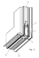
- Fig. 1 a designed as an angle fitting for locking a door or window sash of a sash profile 2 with respect to a window frame profile 3.
- the sash profile 2 and also the frame profile 3 are preferably formed in a thermally insulated design.
- a so-called screw 22 is provided which allows a good grip for screws for fastening hinges, locks, striker plates or the like.
- Both the sash profile 2 and the frame profile 3 have in the region of the insulating piece 21 a groove arrangement 23 for receiving a seal or the like.
- the fitting 1 in this case has a transverse leg 4 and a longitudinal leg 5.
- the grooves 6 may have an undercut or the like.
- grooves 6 are pulled around the corner, so run continuously from the Longitudinal leg 5 to the transverse leg. 4
- a recess 8 is provided, which extends over the entire length of the longitudinal leg 5 and protrudes with its one end through the transverse leg 4.
- a closing mandrel 9 is mounted longitudinally displaceable.
- the cross section of the recess 8 is matched to the cross section of the closing dome 9, so that it is guided without play in the recess 8.
- an opening 10 of the longitudinal leg 5 may be provided, in which a thickening 11 of the closing dome 9 is able to intervene.
- the length of the lock dome 9, the recess 8 and the length of the longitudinal leg 5 are coordinated so that the closing dome 9 does not reach the maximum Naturalragein in normal operation.
- a connection possibility with a push rod 12 or the like is provided at the end facing away from the transverse leg 4 of the locking mandrel 9.
- an unillustrated, projecting rearward nose is provided in the region of the thickening 11 of the lock dome 9, which engages in a corresponding, not shown recess of the push rod 12.
- the width of the fitting 1 is adjusted so that it can be inserted into the groove assembly 23.
- the fitting 1 at the side edges of the longitudinal leg 5 outwardly projecting lugs 13 which are able to intervene in the groove assembly 23.
- the groove assembly 23 is designed so that they are accessible from below, so from the cross member of the sash profile 2.
- the fitting is inserted from the transverse spar forth in the groove assembly 23 and then secured by a fastening screw 14.
- the fastening screw 14 engages in the screw 22 of the insulating piece 21 a.
- the push rod 12 is also matched to the width of the groove assembly 23 and can be moved longitudinally there.
- the push rod 12 is actuated usually via a lock, not shown, or a lever arrangement.
- This lock is arranged, for example, within the insulating piece 21 and usually touches none of the aluminum profiles, so that the reduced heat transfer through the airfoils 2 and the frame profiles 3 is maintained.
- the push rod 12 may be made of a plastic as well as the fitting 1, which has a low thermal conductivity.
- polyamides, in particular PA 6, have proven advantageous, which may be fiber-reinforced.
- the closing dome 9 is usually made of steel or the like, so that it can absorb the shear forces occurring.
- a stop piece is provided which reduces the air gap between the fitting 1 and the frame profile 3 to the minimum degree necessary so as to avoid the fitting at high loads, as may occur, for example, in a break-in attempt , to avoid.
- the seal used in the fitting 1 8 can apply to corresponding contact surfaces of the frame 3 and just to improve the not optimal in the profile corners seal against drafts and increased cold passage significantly.
- sealing profile 8 may still be provided an approach that is able to engage in a frame seal profile 81.
- the attachment of the sealing profile 8 is thus further improved.
- a perforated plate 15 may be provided, which is screwed onto the frame 3 or on a bottom bar 31 and a recording of the lock dome 9 allows.
- a fitting is provided for use with window sashes or the upper closure in the case of door wings, which is insertable into a groove arrangement 23 in the frame profile 3.
- This shaped piece can also be designed as an angle and thus engage both in the longitudinal and the transverse spar of the frame 3.
- Deflectors as they have been customary to allow an off-center locking, the lock sitting in such arrangements with great insulation often centered, can be omitted.
Landscapes
- Engineering & Computer Science (AREA)
- Mechanical Engineering (AREA)
- Civil Engineering (AREA)
- Structural Engineering (AREA)
- Specific Sealing Or Ventilating Devices For Doors And Windows (AREA)
- Wing Frames And Configurations (AREA)
- Window Of Vehicle (AREA)
Abstract
Description
- Die Erfindung bezieht sich auf einen Beschlag für eine Tür oder Fensteranordnung.
- Es sind verschiedenste Beschläge zum Verriegeln von Tür- und Fensteranordnungen bekannt. Diese verriegeln jedoch meistens gegenüber einem seitlichen, vertikal verlaufenden Rahmenteil oder gegenüber einem zweiten Flügel.
- Diese bekannten Verriegelungen sind jedoch in Bezug auf Sicherheit oftmals nicht besonders zuverlässig.
- Gerade bei wärmegedämmten Flügel- und Blendrahmenprofilen, wie sie aus der
DE 10 2008 022 893 A1 bekannt sind, sind bislang keine zufriedenstellenden Lösungen zur Mehrfach-Verriegelung der Tür- und Fensteranordnungen bekannt. - Der vorliegenden Erfindung liegt daher die Aufgabe zugrunde, einen Beschlag vorzuschlagen, der eine sehr sichere und dennoch einfache Verriegelung von Fenster- und Türanordnungen ermöglicht und dennoch die thermische Entkopplung der beiden Seiten der Fenster- und/oder Türanordnung nicht negativ beeinflusst.
- Diese Aufgabe wird erfindungsgemäß dadurch gelöst, daß eine als Eckwinkel ausgebildete Führung vorgesehen ist, in der ein Schließdom längsverschiebbar gehalten wird.
- Durch diese Ausgestaltung kann der Beschlag mittig, zum Beispiel im Bereich der thermischen
- Entkopellung des Rahmen- oder Flügelprofils angeordnet werden. Dabei ist es denkbar, daß der Beschlag aus Kunststoff gefertigt ist.
- Es hat sich erfindungsgemäß auch als sehr vorteilhaft erwiesen, wenn der Beschlag im wesentlichen symmetrisch ausgebildet ist.
- Damit kann der Beschlag in beliebiger Orientierung eingebaut werden. Es ist keine Unterscheidung zwischen Links- oder Rechtsanschlag und Unten- oder Obenanordnung nötig.
- Sehr vorteilhaft ist es erfindungsgemäß, wenn an Vorder- und/oder Hinterkante des Beschlages eine Nut zur Aufnahme eines Dichtungsprofils vorgesehen ist, wobei diese Aufnahme auch an den beiden Schenkeln des als Winkel ausgebildeten Beschlages vorgesehen sein kann.
- Damit kann je nach Einsatzort des Beschlages an der jeweils passenden Stelle ein Dichtungsprofil eingesetzt werden, welches auch um die durch den Beschlag definierte Kante herumgeführt werden kann.
- Ebenfalls sehr vorteilhaft ist es erfindungsgemäß, wenn der Schließdom im wesentlichen formschlüssig im Beschlag gelagert ist.
- Hierdurch wird ein stabiler Sitz des Schließdoms und eine große Widerstandsfähigkeit gegenüber Einbruchsversuchen oder dergleichen erzielt.
- Äußerst vorteilhaft ist es auch, wenn eine die gesamte Beschlagdicke einnehmende Führung für den Schließdom vorgesehen ist.
- Damit wird eine nochmals verbesserte Krafteinleitung in das Beschlagstück sichergestellt.
- Gemäß einer weiteren Ausgestaltung der Erfindung ist es sehr vorteilhaft, wenn der Beschlag eine Dicke aufweist, die den zur Verfügung stehenden Spalt zwischen Flügel und Rahmen weitestgehend ausfüllt.
- Dadurch wird ein unerwünschtes Ausweichen des Beschlages bei großen Belastungen vermieden.
- Als äußerst vorteilhaft hat es sich erfindungsgemäß auch erwiesen, wenn der Beschlag für eine mittige Anordnung am Flügel ausgerüstet ist.
- Durch die mittige Anordnung wird eine besonders geringe Beeinflussung der thermischen Entkopplung sichergestellt.
- Eine sehr vorteilhafte Fortbildung der Erfindung liegt auch vor, wenn der Schließdom im einen Schenkel, dem Längsschenkel des Beschlages gelagert ist und durch den anderen Schenkel, den Querschenkel hindurchtritt.
- Hierdurch wird eine sehr lange Lagerstrecke geschaffen, so daß die seitliche Lagerung des Schließdomes sehr stabil ist. Punktuelle Belastungen und Überbelastungen werden vermieden.
- Sehr vorteilhaft ist es erfindungsgemäß auch, wenn eine Befestigungsmöglichkeit im Querschenkel des Beschlages vorgesehen ist, die als Schraubverbindung vorgesehen sein kann.
- Hiermit kann der Beschlag auf einfache Art und Weise mit dem Flügel verbunden werden. Die Nutzung von in der thermischen Entkopplung vorgesehenen Schraubbereichen ist denkbar.
- Zudem ist es äußerst vorteilhaft, wenn der Längsschenkel des Beschlages derart ausgebildet ist, daß sich dieser in das Profil des Flügel einzupassen vermag und so in Querrichtung gehalten wird.
- Durch das Einsetzen des Längsschenkels des Beschlages in entsprechende Nuten bzw. Ausnehmungen des Flügelprofils wird ein ausgezeichneter Halt erreicht.
- Eine weitere sehr vorteilhafte Ausgestaltung der Erfindung liegt auch vor, wenn der Schließdom im wesentlichen mittig im Beschlag angeordnet ist.
- Hierdurch werden ungleichmäßige Belastungen der Profile vermieden. Zudem kann der Verzug durch Temperaturunterschiede auf Außen- und Innenseite verringert werden und/oder sichergestellt werden, daß die Schließfunktion auch bei Verzug noch leicht bedienbar ist.
- Erfindungsgemäß hat es sich auch als sehr vorteilhaft erwiesen, wenn der Schließdom ein Verbindungselement zu einer Schubstange oder dergleichen aufweist.
- Damit wird eine Bedienbarkeit des Schließdomes über ein zentrales Schloß oder dergleichen ermöglicht.
- Im folgenden wird die Erfindung anhand eines Ausführungsbeispiels veranschaulicht.
- Dabei zeigen:
- Fig. 1
- ein Schaubild des erfindungsgemäßen Beschlages, angebaut an ein Flügelrahmenprofil,
- Fig. 2
- ein Schaubild desselben Beschlages mit ausgefahrenem Schließdom,
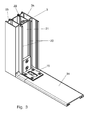
- Fig. 3
- ein Schaubild eines Gegenstücks am Blendrahmenprofil zur Verriegelung mit dem erfindungsgemäßen Beschlag, und
- Fig. 4
- einen Schnitt durch den Querschenkel des erfindungsgemäßen Beschlages.
- Mit 1 ist in
Fig. 1 ein als Winkel ausgebildeter Beschlag zum Verriegeln eines Tür- oder Fensterflügels aus einem Flügelprofil 2 gegenüber einem Blendrahmenprofil 3 bezeichnet. - Das Flügelprofil 2 und auch das Blendrahmenprofil 3 sind vorzugsweise in thermisch isolierter Ausführung ausgebildet. Dies bedeutet, daß vorzugsweise zwei Aluminiumprofile 2a, 2b bzw. 3a, 3b im Abstand voneinander angeordnet sind und diese mit einem vorzugsweise aus einem Kunststoff gefertigten Isolierstück 21 miteinander verbunden sind. In der Mitte des Isolierstückes 21 ist ein sogenannter Schraubkanal 22 vorgesehen, der einen guten Halt für Schrauben zur Befestigung von Scharnieren, Schlössern, Schließplatten oder dergleichen erlaubt.
- Sowohl das Flügelprofil 2 als auch das Blendrahmenprofil 3 weisen im Bereich des Isolierstücks 21 eine Nutanordnung 23 zur Aufnahme einer Dichtung oder dergleichen auf.
- Der Beschlag 1 weist dabei einen Querschenkel 4 und einen Längsschenkel 5 auf.
- Entlang der Seitenkanten des Beschlages 1 sind Nuten 6 vorgesehen, in die ein Dichtprofil 7 einsetzbar ist. Die Nuten 6 können dabei eine Hinterschneidung oder dergleichen aufweisen.
- Zudem sind die Nuten 6 um die Ecke herumgezogen, verlaufen also durchgehend vom Längsschenkel 5 zum Querschenkel 4.
- Im Längsschenkel 5 ist eine Ausnehmung 8 vorgesehen, die sich über die gesamte Länge des Längsschenkels 5 erstreckt und mit ihrem einen Ende durch den Querschenkel 4 hindurchragt. In dieser Ausnehmung 8 ist ein Schließdorn 9 längsverschiebbar gelagert. Der Querschnitt der Ausnehmung 8 ist dabei auf den Querschnitt des Schließdoms 9 abgestimmt, so daß dieser spielfrei in der Ausnehmung 8 geführt wird.
- Am vom Querschenkel 4 abgewandten Ende der Ausnehmung 8 kann eine Durchbrechung 10 des Längsschenkels 5 vorgesehen sein, in die eine Verdickung 11 des Schließdoms 9 einzugreifen vermag.
- Durch die Geometrie der Ausnehmung 8 und die Länge des Längsschenkels 5 kann vorgegeben werden, wie weit der Schließdom 9 durch den Beschlag 1 maximal hindurchragen kann.
- Oftmals sind die Länge des Schließdomes 9, die Ausnehmung 8 und die Länge des Längsschenkels 5 so aufeinander abgestimmt, daß der Schließdom 9 die maximale Durchragelänge im Normalbetrieb nicht erreicht.
- Am vom Querschenkel 4 abgewandten Ende des Schließdornes 9 ist eine Verbindungsmöglichkeit mit einer Schubstange 12 oder dergleichen vorgesehen. Im dargestellten Ausführungsbeispiel ist im Bereich der Verdickung 11 des Schließdomes 9 eine nicht dargestellte, nach hinten ragende Nase vorgesehen, die in eine entsprechende, ebenfalls nicht dargestellte Ausnehmung der Schubstange 12 eingreift.
- Die Breite des Beschlages 1 ist so abgestimmt, daß dieser in die Nutanordnung 23 eingesetzt werden kann.
- In diesem Zusammenhang ist es denkbar, daß der Beschlag 1 an den Seitenkanten des Längsschenkels 5 nach außen ragende Ansätze 13 aufweist, die in die Nutanordnung 23 einzugreifen vermögen. Hierzu ist die Nutanordnung 23 so ausgestaltet, daß diese von unten her, also vom Querholm des Flügelprofils 2 zugänglich sind.
- Durch diese Ansätze 13 wird ein Herausrutschen oder Heraushebeln des Beschlages 1 aus der Nutanordnung 23 verhindert.
- Der Beschlag wird dazu vom Querholm her in die Nutanordnung 23 eingeschoben und dann durch eine Befestigungsschraube 14 gesichert. Die Befestigungsschraube 14 greift dabei in den Schraubkanal 22 des Isolierstücks 21 ein.
- Die Schubstange 12 ist ebenfalls auf die Breite der Nutanordnung 23 abgestimmt und kann dort längs verschoben werden. Die Schubstange 12 wird dabei in der Regel über ein nicht dargestelltes Schloß oder eine Hebelanordnung betätigt. Dieses Schloß ist beispielsweise innerhalb des Isolierstücks 21 angeordnet und berührt in der Regel keines der Aluminiumprofile, so daß der verminderte Wärmetransport durch die Flügelprofile 2 und die Blendrahmenprofile 3 aufrechterhalten bleibt.
- Die Schubstange 12 kann ebenso wie der Beschlag 1 aus einem Kunststoff gefertigt sein, der eine geringe Wärmeleitfähigkeit aufweist. Vorteilhaft haben sich hierzu Polyamide, insbesondere PA 6 erwiesen, die faserverstärkt sein können.
- Diese bieten eine hohe Festigkeit und Schlagzähigkeit.
- Der Schließdom 9 ist in der Regel aus Stahl oder dergleichen gefertigt, damit dieser die auftretenden Scherkräfte aufnehmen kann.
- Es ist denkbar, daß im gegenüberliegenden Blendrahmenprofil 3 noch ein Anschlagstück vorgesehen ist, welches den Luftspalt zwischen dem Beschlag 1 und dem Blendrahmenprofil 3 auf das mindestens notwendige Maß verkleinert um so ein Ausweichen des Beschlages bei großen Belastungen, wie diese beispielsweise bei einem Einbruchsversuch auftreten können, zu vermeiden.
- Die in den Beschlag 1 eingesetzte Dichtung 8 vermag sich an entsprechenden Anlageflächen des Blendrahmens 3 anzulegen und gerade die in den Profilecken nicht optimale Abdichtung gegen Zugluft und vergrößerten Kältedurchgang deutlich zu verbessern.
- Durch die symmetrische Ausgestaltung des Beschlages 1 ist dieser an allen vier Ecken eines Flügelprofils 2 einsetzbar. Dabei ist es unerheblich ob dieses für Linksanschlag oder Rechtsanschlag eingerichtet ist.
- Für das Dichtungsprofil 8 brauchen auch nur zwei Varianten vorgehalten werden um den Einsatz an allen vier Profilecken zu ermöglichen.
- Am Ende des Dichtungsprofils 8 kann noch ein Ansatz vorgesehen sein, der in ein Rahmendichtungsprofil 81 einzugreifen vermag. Die Befestigung des Dichtungsprofils 8 wird damit nochmals verbessert.
- Als Gegenstück für den Beschlag 1 kann eine Lochplatte 15 vorgesehen sein, die auf dem Blendrahmen 3 oder auf einer Bodenleiste 31 aufgeschraubt ist und eine Aufnahme des Schließdomes 9 ermöglicht.
- Es ist auch denkbar, daß gerade für den Einsatz bei Fensterflügeln oder die obere Schließung bei Türflügeln ein Formstück vorgesehen ist, welches in eine Nutanordnung 23 im Blendrahmenprofil 3 einsetzbar ist. Dieses nicht dargestellte Formstück kann dabei auch als Winkel ausgebildet sein und damit sowohl in den Längs- als auch den Querholm des Blendrahmens 3 eingreifen.
- Insgesamt wird durch die erfindungsgemäße Beschlaganordnung eine Möglichkeit geschaffen, die eine mittige Verriegelung in Vertikalrichtung ermöglicht, ohne die Isolierung der Profile negativ zu beeinflussen.
- Umlenkungen, wie sie bislang üblich waren, um eine außermittige Verriegelung zu ermöglichen, das Schloß sitzt bei solchen Anordnungen mit großer Isolierwirkung oftmals mittig, können entfallen.
Claims (12)
- Beschlag für eine Tür oder Fensteranordnung, dadurch gekennzeichnet, daß eine als Eckwinkel ausgebildete Führung vorgesehen ist, in der ein Schließdom längsverschiebbar gehalten wird.
- Beschlag nach Anspruch 1, dadurch gekennzeichnet, daß der Beschlag im wesentlichen symmetrisch ausgebildet ist.
- Beschlag nach Anspruch 1 oder 2, dadurch gekennzeichnet, daß an Vorder- und/oder Hinterkante des Beschlages eine Nut zur Aufnahme eines Dichtungsprofils vorgesehen ist, wobei diese Aufnahme auch an den beiden Schenkeln des als Winkel ausgebildeten Beschlages vorgesehen sein kann.
- Beschlag nach Anspruch 1, 2 oder 3, dadurch gekennzeichnet, daß der Schließdom im wesentlichen formschlüssig im Beschlag gelagert ist.
- Beschlag nach einem der vorangehenden Ansprüche, dadurch gekennzeichnet, daß eine die gesamte Beschlagdicke einnehmende Führung für den Schließdom vorgesehen ist.
- Beschlag nach einem der vorangehenden Ansprüche, dadurch gekennzeichnet, daß der Beschlag eine Dicke aufweist, die den zur Verfügung stehenden Spalt zwischen Flügel und Rahmen weitestgehend ausfüllt.
- Beschlag nach einem der vorangehenden Ansprüche, dadurch gekennzeichnet, daß der Beschlag für eine mittige Anordnung am Flügel ausgerüstet ist.
- Beschlag nach einem der vorangehenden Ansprüche, dadurch gekennzeichnet, daß der Schließdom im einen Schenkel, dem Längsschenkel des Beschlages gelagert ist und durch den anderen Schenkel, den Querschenkel hindurchtritt.
- Beschlag nach einem der vorangehenden Ansprüche, dadurch gekennzeichnet, daß eine Befestigungsmöglichkeit im Querschenkel des Beschlages vorgesehen ist, die als Schraubverbindung vorgesehen sein kann.
- Beschlag nach einem der vorangehenden Ansprüche, dadurch gekennzeichnet, daß der Längsschenkel des Beschlages derart ausgebildet ist, daß sich dieser in das Profil des Flügel einzupassen vermag und so in Querrichtung gehalten wird.
- Beschlag nach einem der vorangehenden Ansprüche, dadurch gekennzeichnet, daß der Schließdom im wesentlichen mittig im Beschlag angeordnet ist.
- Beschlag nach einem der vorangehenden Ansprüche, dadurch gekennzeichnet, daß der Schließdom ein Verbindungselement zu einer Schubstange oder dergleichen aufweist.
Applications Claiming Priority (1)
| Application Number | Priority Date | Filing Date | Title |
|---|---|---|---|
| DE102011055037A DE102011055037A1 (de) | 2011-11-04 | 2011-11-04 | Beschlag |
Publications (3)
| Publication Number | Publication Date |
|---|---|
| EP2589739A2 true EP2589739A2 (de) | 2013-05-08 |
| EP2589739A3 EP2589739A3 (de) | 2017-05-10 |
| EP2589739B1 EP2589739B1 (de) | 2019-06-05 |
Family
ID=47143006
Family Applications (1)
| Application Number | Title | Priority Date | Filing Date |
|---|---|---|---|
| EP12191100.2A Active EP2589739B1 (de) | 2011-11-04 | 2012-11-02 | Beschlag |
Country Status (2)
| Country | Link |
|---|---|
| EP (1) | EP2589739B1 (de) |
| DE (1) | DE102011055037A1 (de) |
Cited By (3)
| Publication number | Priority date | Publication date | Assignee | Title |
|---|---|---|---|---|
| US20230151677A1 (en) * | 2021-09-10 | 2023-05-18 | Andersen Corporation | Sill corner brackets for coastal impact resistant fenestrations |
| US12460457B2 (en) | 2021-09-10 | 2025-11-04 | Andersen Corporation | Sash tilt bolt and checkrail bracket systems for coastal impact resistant fenestrations |
| US12577828B2 (en) | 2021-09-10 | 2026-03-17 | Andersen Corporation | Coastal impact resistant fenestrations including corner key with overlap geometry |
Families Citing this family (1)
| Publication number | Priority date | Publication date | Assignee | Title |
|---|---|---|---|---|
| DE102018116417A1 (de) | 2018-07-06 | 2020-01-09 | Roto Frank Fenster- und Türtechnologie GmbH | Vormontierte Beschlaggruppe und Beschlaganordnung für ein Fenster oder eine Tür |
Citations (1)
| Publication number | Priority date | Publication date | Assignee | Title |
|---|---|---|---|---|
| DE102008022893A1 (de) | 2008-05-08 | 2009-11-19 | Hydro Aluminium As | Tür, Fenster oder dergleichen in wärmegedämmter Ausführung |
Family Cites Families (7)
| Publication number | Priority date | Publication date | Assignee | Title |
|---|---|---|---|---|
| AT361328B (de) * | 1972-08-07 | 1981-03-10 | Goetz Metallbau Gmbh | Rahmengetriebe fuer ein metallfenster |
| DE8127451U1 (de) * | 1981-09-19 | 1982-01-28 | Siegenia-Frank Kg, 5900 Siegen | Eckumlenkung fuer treibstangenbeschlaege |
| DE9317965U1 (de) * | 1993-11-24 | 1994-03-03 | Mekuwa Metall- und Kunststoff-Fertigungs GmbH Walldorf, 64546 Mörfelden-Walldorf | Beschlag für eine Klappe oder ein Klappenfenster |
| GB9705317D0 (en) * | 1997-03-14 | 1997-04-30 | Btr Industries Ltd | Window or door latching mechanisms |
| FR2849091B1 (fr) * | 2002-12-19 | 2005-09-23 | Ferco Int Usine Ferrures | Guide de sortie de tringle pour cremone, cremone-serrure ou similaire |
| ITBO20030723A1 (it) * | 2003-11-28 | 2005-05-29 | Gsg Int Spa | Elemento di rinvio angolare per infissi. |
| GB2474644A (en) * | 2009-10-20 | 2011-04-27 | Giovanni Maria Laporta | Frame member with bolt receiving channel |
-
2011
- 2011-11-04 DE DE102011055037A patent/DE102011055037A1/de not_active Withdrawn
-
2012
- 2012-11-02 EP EP12191100.2A patent/EP2589739B1/de active Active
Patent Citations (1)
| Publication number | Priority date | Publication date | Assignee | Title |
|---|---|---|---|---|
| DE102008022893A1 (de) | 2008-05-08 | 2009-11-19 | Hydro Aluminium As | Tür, Fenster oder dergleichen in wärmegedämmter Ausführung |
Cited By (4)
| Publication number | Priority date | Publication date | Assignee | Title |
|---|---|---|---|---|
| US20230151677A1 (en) * | 2021-09-10 | 2023-05-18 | Andersen Corporation | Sill corner brackets for coastal impact resistant fenestrations |
| US11939811B2 (en) * | 2021-09-10 | 2024-03-26 | Andersen Corporation | Sill corner brackets for coastal impact resistant fenestrations |
| US12460457B2 (en) | 2021-09-10 | 2025-11-04 | Andersen Corporation | Sash tilt bolt and checkrail bracket systems for coastal impact resistant fenestrations |
| US12577828B2 (en) | 2021-09-10 | 2026-03-17 | Andersen Corporation | Coastal impact resistant fenestrations including corner key with overlap geometry |
Also Published As
| Publication number | Publication date |
|---|---|
| EP2589739B1 (de) | 2019-06-05 |
| DE102011055037A1 (de) | 2013-05-08 |
| EP2589739A3 (de) | 2017-05-10 |
Similar Documents
| Publication | Publication Date | Title |
|---|---|---|
| EP2116685B1 (de) | Tür, Fenster oder dergleichen in wärmegedämmter Ausführung | |
| DE102016125602B4 (de) | Isolierkörper für mehrschalige Bauelemente | |
| EP3798390B1 (de) | Faltanlage | |
| EP2589739B1 (de) | Beschlag | |
| EP2752539B2 (de) | Treibriegelschloss | |
| EP2407604B1 (de) | Verbindungsvorrichtung | |
| EP2473691B1 (de) | Laufwagengehäuse für eine hebe-schiebe-tür oder ein hebe-schiebe-fenster sowie hebe-schiebe-tür oder hebe-schiebe-fenster, die/das ein derartiges laufwagengehäuse umfasst | |
| EP2113624B1 (de) | Tür- oder Fenstersicherungsvorrichtung | |
| EP2792830A2 (de) | Halteelement zur Halterung eines Beschlagteils | |
| EP3375962B1 (de) | Zusatzverriegelung für eine türanordnung | |
| EP3192957B1 (de) | Vorrichtung zur bildung eines wandanschlusses | |
| EP2871306B1 (de) | Anordnung mit einem Riegelstangenbeschlag an einem Rahmenholm | |
| EP2369115A2 (de) | Aushebesicherung für Schiebefenster oder Schiebetüren | |
| EP2754804A2 (de) | Verschluss für einen Treibstangenbeschlag | |
| EP2853670B1 (de) | Laufschiene für eine Schiebetür | |
| EP2607583B1 (de) | Beschlagteil für einen treibstangenbeschlag | |
| EP2339095B1 (de) | Tür, insbesondere Kunstofftür, mit einer Schlosskastensicherung | |
| EP2132391B1 (de) | Treibstangenanordnung mit mindestens einer treibstange und mindestens einem treibstangenführungselement | |
| EP0725202A1 (de) | Bewehrung an Türen oder Fenstern | |
| EP3162994B1 (de) | Antriebsgetriebe für einen treibstangenbeschlag | |
| EP3816383A1 (de) | Schiebetüranordnung | |
| DE102017100334A1 (de) | Rahmenprofil mit Profilleiste für Beschlag | |
| DE19937891C1 (de) | Schaltschrank | |
| EP0829603A2 (de) | Verriegelungseinsatz für Türen- oder Fensterprofile | |
| DE19857384C2 (de) | Befestigungsmittel zum Verbinden eines Flügelrahmens mit einem Blendrahmen zu einem nicht öffenbaren Fenster |
Legal Events
| Date | Code | Title | Description |
|---|---|---|---|
| PUAI | Public reference made under article 153(3) epc to a published international application that has entered the european phase |
Free format text: ORIGINAL CODE: 0009012 |
|
| AK | Designated contracting states |
Kind code of ref document: A2 Designated state(s): AL AT BE BG CH CY CZ DE DK EE ES FI FR GB GR HR HU IE IS IT LI LT LU LV MC MK MT NL NO PL PT RO RS SE SI SK SM TR |
|
| AX | Request for extension of the european patent |
Extension state: BA ME |
|
| RIN1 | Information on inventor provided before grant (corrected) |
Inventor name: EICKHOFF, HEINRICH Inventor name: HIRNIGEL, REINHARD Inventor name: SCHEFFEL, MATTHIAS |
|
| RAP1 | Party data changed (applicant data changed or rights of an application transferred) |
Owner name: SAPA AS |
|
| PUAL | Search report despatched |
Free format text: ORIGINAL CODE: 0009013 |
|
| AK | Designated contracting states |
Kind code of ref document: A3 Designated state(s): AL AT BE BG CH CY CZ DE DK EE ES FI FR GB GR HR HU IE IS IT LI LT LU LV MC MK MT NL NO PL PT RO RS SE SI SK SM TR |
|
| AX | Request for extension of the european patent |
Extension state: BA ME |
|
| RIC1 | Information provided on ipc code assigned before grant |
Ipc: E06B 3/263 20060101AFI20170406BHEP Ipc: E05B 63/04 20060101ALN20170406BHEP Ipc: E05C 7/04 20060101ALI20170406BHEP |
|
| STAA | Information on the status of an ep patent application or granted ep patent |
Free format text: STATUS: REQUEST FOR EXAMINATION WAS MADE |
|
| 17P | Request for examination filed |
Effective date: 20170918 |
|
| RBV | Designated contracting states (corrected) |
Designated state(s): AL AT BE BG CH CY CZ DE DK EE ES FI FR GB GR HR HU IE IS IT LI LT LU LV MC MK MT NL NO PL PT RO RS SE SI SK SM TR |
|
| STAA | Information on the status of an ep patent application or granted ep patent |
Free format text: STATUS: EXAMINATION IS IN PROGRESS |
|
| 17Q | First examination report despatched |
Effective date: 20180405 |
|
| GRAP | Despatch of communication of intention to grant a patent |
Free format text: ORIGINAL CODE: EPIDOSNIGR1 |
|
| STAA | Information on the status of an ep patent application or granted ep patent |
Free format text: STATUS: GRANT OF PATENT IS INTENDED |
|
| RIC1 | Information provided on ipc code assigned before grant |
Ipc: E06B 3/263 20060101AFI20181113BHEP Ipc: E05B 63/04 20060101ALN20181113BHEP Ipc: E05C 7/04 20060101ALI20181113BHEP |
|
| INTG | Intention to grant announced |
Effective date: 20181213 |
|
| GRAS | Grant fee paid |
Free format text: ORIGINAL CODE: EPIDOSNIGR3 |
|
| GRAA | (expected) grant |
Free format text: ORIGINAL CODE: 0009210 |
|
| STAA | Information on the status of an ep patent application or granted ep patent |
Free format text: STATUS: THE PATENT HAS BEEN GRANTED |
|
| AK | Designated contracting states |
Kind code of ref document: B1 Designated state(s): AL AT BE BG CH CY CZ DE DK EE ES FI FR GB GR HR HU IE IS IT LI LT LU LV MC MK MT NL NO PL PT RO RS SE SI SK SM TR |
|
| REG | Reference to a national code |
Ref country code: GB Ref legal event code: FG4D Free format text: NOT ENGLISH |
|
| REG | Reference to a national code |
Ref country code: CH Ref legal event code: EP |
|
| REG | Reference to a national code |
Ref country code: AT Ref legal event code: REF Ref document number: 1140136 Country of ref document: AT Kind code of ref document: T Effective date: 20190615 |
|
| REG | Reference to a national code |
Ref country code: IE Ref legal event code: FG4D Free format text: LANGUAGE OF EP DOCUMENT: GERMAN |
|
| REG | Reference to a national code |
Ref country code: DE Ref legal event code: R096 Ref document number: 502012014864 Country of ref document: DE |
|
| REG | Reference to a national code |
Ref country code: NL Ref legal event code: MP Effective date: 20190605 |
|
| REG | Reference to a national code |
Ref country code: LT Ref legal event code: MG4D |
|
| PG25 | Lapsed in a contracting state [announced via postgrant information from national office to epo] |
Ref country code: FI Free format text: LAPSE BECAUSE OF FAILURE TO SUBMIT A TRANSLATION OF THE DESCRIPTION OR TO PAY THE FEE WITHIN THE PRESCRIBED TIME-LIMIT Effective date: 20190605 Ref country code: SE Free format text: LAPSE BECAUSE OF FAILURE TO SUBMIT A TRANSLATION OF THE DESCRIPTION OR TO PAY THE FEE WITHIN THE PRESCRIBED TIME-LIMIT Effective date: 20190605 Ref country code: HR Free format text: LAPSE BECAUSE OF FAILURE TO SUBMIT A TRANSLATION OF THE DESCRIPTION OR TO PAY THE FEE WITHIN THE PRESCRIBED TIME-LIMIT Effective date: 20190605 Ref country code: ES Free format text: LAPSE BECAUSE OF FAILURE TO SUBMIT A TRANSLATION OF THE DESCRIPTION OR TO PAY THE FEE WITHIN THE PRESCRIBED TIME-LIMIT Effective date: 20190605 Ref country code: LT Free format text: LAPSE BECAUSE OF FAILURE TO SUBMIT A TRANSLATION OF THE DESCRIPTION OR TO PAY THE FEE WITHIN THE PRESCRIBED TIME-LIMIT Effective date: 20190605 Ref country code: AL Free format text: LAPSE BECAUSE OF FAILURE TO SUBMIT A TRANSLATION OF THE DESCRIPTION OR TO PAY THE FEE WITHIN THE PRESCRIBED TIME-LIMIT Effective date: 20190605 Ref country code: NO Free format text: LAPSE BECAUSE OF FAILURE TO SUBMIT A TRANSLATION OF THE DESCRIPTION OR TO PAY THE FEE WITHIN THE PRESCRIBED TIME-LIMIT Effective date: 20190905 |
|
| PG25 | Lapsed in a contracting state [announced via postgrant information from national office to epo] |
Ref country code: LV Free format text: LAPSE BECAUSE OF FAILURE TO SUBMIT A TRANSLATION OF THE DESCRIPTION OR TO PAY THE FEE WITHIN THE PRESCRIBED TIME-LIMIT Effective date: 20190605 Ref country code: GR Free format text: LAPSE BECAUSE OF FAILURE TO SUBMIT A TRANSLATION OF THE DESCRIPTION OR TO PAY THE FEE WITHIN THE PRESCRIBED TIME-LIMIT Effective date: 20190906 Ref country code: RS Free format text: LAPSE BECAUSE OF FAILURE TO SUBMIT A TRANSLATION OF THE DESCRIPTION OR TO PAY THE FEE WITHIN THE PRESCRIBED TIME-LIMIT Effective date: 20190605 Ref country code: BG Free format text: LAPSE BECAUSE OF FAILURE TO SUBMIT A TRANSLATION OF THE DESCRIPTION OR TO PAY THE FEE WITHIN THE PRESCRIBED TIME-LIMIT Effective date: 20190905 |
|
| PG25 | Lapsed in a contracting state [announced via postgrant information from national office to epo] |
Ref country code: CZ Free format text: LAPSE BECAUSE OF FAILURE TO SUBMIT A TRANSLATION OF THE DESCRIPTION OR TO PAY THE FEE WITHIN THE PRESCRIBED TIME-LIMIT Effective date: 20190605 Ref country code: RO Free format text: LAPSE BECAUSE OF FAILURE TO SUBMIT A TRANSLATION OF THE DESCRIPTION OR TO PAY THE FEE WITHIN THE PRESCRIBED TIME-LIMIT Effective date: 20190605 Ref country code: PT Free format text: LAPSE BECAUSE OF FAILURE TO SUBMIT A TRANSLATION OF THE DESCRIPTION OR TO PAY THE FEE WITHIN THE PRESCRIBED TIME-LIMIT Effective date: 20191007 Ref country code: NL Free format text: LAPSE BECAUSE OF FAILURE TO SUBMIT A TRANSLATION OF THE DESCRIPTION OR TO PAY THE FEE WITHIN THE PRESCRIBED TIME-LIMIT Effective date: 20190605 Ref country code: EE Free format text: LAPSE BECAUSE OF FAILURE TO SUBMIT A TRANSLATION OF THE DESCRIPTION OR TO PAY THE FEE WITHIN THE PRESCRIBED TIME-LIMIT Effective date: 20190605 Ref country code: SK Free format text: LAPSE BECAUSE OF FAILURE TO SUBMIT A TRANSLATION OF THE DESCRIPTION OR TO PAY THE FEE WITHIN THE PRESCRIBED TIME-LIMIT Effective date: 20190605 |
|
| PG25 | Lapsed in a contracting state [announced via postgrant information from national office to epo] |
Ref country code: IT Free format text: LAPSE BECAUSE OF FAILURE TO SUBMIT A TRANSLATION OF THE DESCRIPTION OR TO PAY THE FEE WITHIN THE PRESCRIBED TIME-LIMIT Effective date: 20190605 Ref country code: SM Free format text: LAPSE BECAUSE OF FAILURE TO SUBMIT A TRANSLATION OF THE DESCRIPTION OR TO PAY THE FEE WITHIN THE PRESCRIBED TIME-LIMIT Effective date: 20190605 Ref country code: IS Free format text: LAPSE BECAUSE OF FAILURE TO SUBMIT A TRANSLATION OF THE DESCRIPTION OR TO PAY THE FEE WITHIN THE PRESCRIBED TIME-LIMIT Effective date: 20191005 |
|
| REG | Reference to a national code |
Ref country code: DE Ref legal event code: R097 Ref document number: 502012014864 Country of ref document: DE |
|
| PG25 | Lapsed in a contracting state [announced via postgrant information from national office to epo] |
Ref country code: TR Free format text: LAPSE BECAUSE OF FAILURE TO SUBMIT A TRANSLATION OF THE DESCRIPTION OR TO PAY THE FEE WITHIN THE PRESCRIBED TIME-LIMIT Effective date: 20190605 |
|
| PLBE | No opposition filed within time limit |
Free format text: ORIGINAL CODE: 0009261 |
|
| STAA | Information on the status of an ep patent application or granted ep patent |
Free format text: STATUS: NO OPPOSITION FILED WITHIN TIME LIMIT |
|
| PG25 | Lapsed in a contracting state [announced via postgrant information from national office to epo] |
Ref country code: DK Free format text: LAPSE BECAUSE OF FAILURE TO SUBMIT A TRANSLATION OF THE DESCRIPTION OR TO PAY THE FEE WITHIN THE PRESCRIBED TIME-LIMIT Effective date: 20190605 Ref country code: PL Free format text: LAPSE BECAUSE OF FAILURE TO SUBMIT A TRANSLATION OF THE DESCRIPTION OR TO PAY THE FEE WITHIN THE PRESCRIBED TIME-LIMIT Effective date: 20190605 |
|
| 26N | No opposition filed |
Effective date: 20200306 |
|
| PG25 | Lapsed in a contracting state [announced via postgrant information from national office to epo] |
Ref country code: SI Free format text: LAPSE BECAUSE OF FAILURE TO SUBMIT A TRANSLATION OF THE DESCRIPTION OR TO PAY THE FEE WITHIN THE PRESCRIBED TIME-LIMIT Effective date: 20190605 |
|
| REG | Reference to a national code |
Ref country code: CH Ref legal event code: PL |
|
| PG25 | Lapsed in a contracting state [announced via postgrant information from national office to epo] |
Ref country code: MC Free format text: LAPSE BECAUSE OF FAILURE TO SUBMIT A TRANSLATION OF THE DESCRIPTION OR TO PAY THE FEE WITHIN THE PRESCRIBED TIME-LIMIT Effective date: 20190605 Ref country code: LI Free format text: LAPSE BECAUSE OF NON-PAYMENT OF DUE FEES Effective date: 20191130 Ref country code: CH Free format text: LAPSE BECAUSE OF NON-PAYMENT OF DUE FEES Effective date: 20191130 Ref country code: LU Free format text: LAPSE BECAUSE OF NON-PAYMENT OF DUE FEES Effective date: 20191102 |
|
| REG | Reference to a national code |
Ref country code: BE Ref legal event code: MM Effective date: 20191130 |
|
| GBPC | Gb: european patent ceased through non-payment of renewal fee |
Effective date: 20191102 |
|
| PG25 | Lapsed in a contracting state [announced via postgrant information from national office to epo] |
Ref country code: GB Free format text: LAPSE BECAUSE OF NON-PAYMENT OF DUE FEES Effective date: 20191102 Ref country code: IE Free format text: LAPSE BECAUSE OF NON-PAYMENT OF DUE FEES Effective date: 20191102 |
|
| PG25 | Lapsed in a contracting state [announced via postgrant information from national office to epo] |
Ref country code: BE Free format text: LAPSE BECAUSE OF NON-PAYMENT OF DUE FEES Effective date: 20191130 |
|
| REG | Reference to a national code |
Ref country code: AT Ref legal event code: MM01 Ref document number: 1140136 Country of ref document: AT Kind code of ref document: T Effective date: 20191102 |
|
| PG25 | Lapsed in a contracting state [announced via postgrant information from national office to epo] |
Ref country code: AT Free format text: LAPSE BECAUSE OF NON-PAYMENT OF DUE FEES Effective date: 20191102 |
|
| PG25 | Lapsed in a contracting state [announced via postgrant information from national office to epo] |
Ref country code: CY Free format text: LAPSE BECAUSE OF FAILURE TO SUBMIT A TRANSLATION OF THE DESCRIPTION OR TO PAY THE FEE WITHIN THE PRESCRIBED TIME-LIMIT Effective date: 20190605 |
|
| PG25 | Lapsed in a contracting state [announced via postgrant information from national office to epo] |
Ref country code: HU Free format text: LAPSE BECAUSE OF FAILURE TO SUBMIT A TRANSLATION OF THE DESCRIPTION OR TO PAY THE FEE WITHIN THE PRESCRIBED TIME-LIMIT; INVALID AB INITIO Effective date: 20121102 Ref country code: MT Free format text: LAPSE BECAUSE OF FAILURE TO SUBMIT A TRANSLATION OF THE DESCRIPTION OR TO PAY THE FEE WITHIN THE PRESCRIBED TIME-LIMIT Effective date: 20190605 |
|
| PG25 | Lapsed in a contracting state [announced via postgrant information from national office to epo] |
Ref country code: MK Free format text: LAPSE BECAUSE OF FAILURE TO SUBMIT A TRANSLATION OF THE DESCRIPTION OR TO PAY THE FEE WITHIN THE PRESCRIBED TIME-LIMIT Effective date: 20190605 |
|
| PGFP | Annual fee paid to national office [announced via postgrant information from national office to epo] |
Ref country code: FR Payment date: 20250918 Year of fee payment: 14 |
|
| PGFP | Annual fee paid to national office [announced via postgrant information from national office to epo] |
Ref country code: DE Payment date: 20251014 Year of fee payment: 14 |
|
| REG | Reference to a national code |
Ref country code: DE Ref legal event code: R082 Ref document number: 502012014864 Country of ref document: DE Representative=s name: EISENFUEHR SPEISER PATENTANWAELTE RECHTSANWAEL, DE |