EP2586642B1 - Fahrzeugeingabevorrichtung - Google Patents
Fahrzeugeingabevorrichtung Download PDFInfo
- Publication number
- EP2586642B1 EP2586642B1 EP12190335.5A EP12190335A EP2586642B1 EP 2586642 B1 EP2586642 B1 EP 2586642B1 EP 12190335 A EP12190335 A EP 12190335A EP 2586642 B1 EP2586642 B1 EP 2586642B1
- Authority
- EP
- European Patent Office
- Prior art keywords
- display
- display screen
- cursor
- display area
- touch pad
- Prior art date
- Legal status (The legal status is an assumption and is not a legal conclusion. Google has not performed a legal analysis and makes no representation as to the accuracy of the status listed.)
- Not-in-force
Links
Images



Classifications
-
- G—PHYSICS
- G06—COMPUTING OR CALCULATING; COUNTING
- G06F—ELECTRIC DIGITAL DATA PROCESSING
- G06F3/00—Input arrangements for transferring data to be processed into a form capable of being handled by the computer; Output arrangements for transferring data from processing unit to output unit, e.g. interface arrangements
- G06F3/01—Input arrangements or combined input and output arrangements for interaction between user and computer
- G06F3/048—Interaction techniques based on graphical user interfaces [GUI]
- G06F3/0487—Interaction techniques based on graphical user interfaces [GUI] using specific features provided by the input device, e.g. functions controlled by the rotation of a mouse with dual sensing arrangements, or of the nature of the input device, e.g. tap gestures based on pressure sensed by a digitiser
- G06F3/0488—Interaction techniques based on graphical user interfaces [GUI] using specific features provided by the input device, e.g. functions controlled by the rotation of a mouse with dual sensing arrangements, or of the nature of the input device, e.g. tap gestures based on pressure sensed by a digitiser using a touch-screen or digitiser, e.g. input of commands through traced gestures
- G06F3/04883—Interaction techniques based on graphical user interfaces [GUI] using specific features provided by the input device, e.g. functions controlled by the rotation of a mouse with dual sensing arrangements, or of the nature of the input device, e.g. tap gestures based on pressure sensed by a digitiser using a touch-screen or digitiser, e.g. input of commands through traced gestures for inputting data by handwriting, e.g. gesture or text
-
- B—PERFORMING OPERATIONS; TRANSPORTING
- B60—VEHICLES IN GENERAL
- B60K—ARRANGEMENT OR MOUNTING OF PROPULSION UNITS OR OF TRANSMISSIONS IN VEHICLES; ARRANGEMENT OR MOUNTING OF PLURAL DIVERSE PRIME-MOVERS IN VEHICLES; AUXILIARY DRIVES FOR VEHICLES; INSTRUMENTATION OR DASHBOARDS FOR VEHICLES; ARRANGEMENTS IN CONNECTION WITH COOLING, AIR INTAKE, GAS EXHAUST OR FUEL SUPPLY OF PROPULSION UNITS IN VEHICLES
- B60K35/00—Instruments specially adapted for vehicles; Arrangement of instruments in or on vehicles
- B60K35/10—Input arrangements, i.e. from user to vehicle, associated with vehicle functions or specially adapted therefor
-
- B—PERFORMING OPERATIONS; TRANSPORTING
- B60—VEHICLES IN GENERAL
- B60K—ARRANGEMENT OR MOUNTING OF PROPULSION UNITS OR OF TRANSMISSIONS IN VEHICLES; ARRANGEMENT OR MOUNTING OF PLURAL DIVERSE PRIME-MOVERS IN VEHICLES; AUXILIARY DRIVES FOR VEHICLES; INSTRUMENTATION OR DASHBOARDS FOR VEHICLES; ARRANGEMENTS IN CONNECTION WITH COOLING, AIR INTAKE, GAS EXHAUST OR FUEL SUPPLY OF PROPULSION UNITS IN VEHICLES
- B60K35/00—Instruments specially adapted for vehicles; Arrangement of instruments in or on vehicles
- B60K35/20—Output arrangements, i.e. from vehicle to user, associated with vehicle functions or specially adapted therefor
- B60K35/21—Output arrangements, i.e. from vehicle to user, associated with vehicle functions or specially adapted therefor using visual output, e.g. blinking lights or matrix displays
- B60K35/22—Display screens
-
- B—PERFORMING OPERATIONS; TRANSPORTING
- B60—VEHICLES IN GENERAL
- B60K—ARRANGEMENT OR MOUNTING OF PROPULSION UNITS OR OF TRANSMISSIONS IN VEHICLES; ARRANGEMENT OR MOUNTING OF PLURAL DIVERSE PRIME-MOVERS IN VEHICLES; AUXILIARY DRIVES FOR VEHICLES; INSTRUMENTATION OR DASHBOARDS FOR VEHICLES; ARRANGEMENTS IN CONNECTION WITH COOLING, AIR INTAKE, GAS EXHAUST OR FUEL SUPPLY OF PROPULSION UNITS IN VEHICLES
- B60K35/00—Instruments specially adapted for vehicles; Arrangement of instruments in or on vehicles
- B60K35/60—Instruments characterised by their location or relative disposition in or on vehicles
-
- B—PERFORMING OPERATIONS; TRANSPORTING
- B60—VEHICLES IN GENERAL
- B60K—ARRANGEMENT OR MOUNTING OF PROPULSION UNITS OR OF TRANSMISSIONS IN VEHICLES; ARRANGEMENT OR MOUNTING OF PLURAL DIVERSE PRIME-MOVERS IN VEHICLES; AUXILIARY DRIVES FOR VEHICLES; INSTRUMENTATION OR DASHBOARDS FOR VEHICLES; ARRANGEMENTS IN CONNECTION WITH COOLING, AIR INTAKE, GAS EXHAUST OR FUEL SUPPLY OF PROPULSION UNITS IN VEHICLES
- B60K35/00—Instruments specially adapted for vehicles; Arrangement of instruments in or on vehicles
- B60K35/65—Instruments specially adapted for specific vehicle types or users, e.g. for left- or right-hand drive
- B60K35/654—Instruments specially adapted for specific vehicle types or users, e.g. for left- or right-hand drive the user being the driver
-
- G—PHYSICS
- G06—COMPUTING OR CALCULATING; COUNTING
- G06F—ELECTRIC DIGITAL DATA PROCESSING
- G06F3/00—Input arrangements for transferring data to be processed into a form capable of being handled by the computer; Output arrangements for transferring data from processing unit to output unit, e.g. interface arrangements
- G06F3/01—Input arrangements or combined input and output arrangements for interaction between user and computer
- G06F3/03—Arrangements for converting the position or the displacement of a member into a coded form
- G06F3/033—Pointing devices displaced or positioned by the user, e.g. mice, trackballs, pens or joysticks; Accessories therefor
- G06F3/0354—Pointing devices displaced or positioned by the user, e.g. mice, trackballs, pens or joysticks; Accessories therefor with detection of two-dimensional [2D] relative movements between the device, or an operating part thereof, and a plane or surface, e.g. 2D mice, trackballs, pens or pucks
- G06F3/03547—Touch pads, in which fingers can move on a surface
-
- G—PHYSICS
- G06—COMPUTING OR CALCULATING; COUNTING
- G06F—ELECTRIC DIGITAL DATA PROCESSING
- G06F3/00—Input arrangements for transferring data to be processed into a form capable of being handled by the computer; Output arrangements for transferring data from processing unit to output unit, e.g. interface arrangements
- G06F3/01—Input arrangements or combined input and output arrangements for interaction between user and computer
- G06F3/048—Interaction techniques based on graphical user interfaces [GUI]
- G06F3/0481—Interaction techniques based on graphical user interfaces [GUI] based on specific properties of the displayed interaction object or a metaphor-based environment, e.g. interaction with desktop elements like windows or icons, or assisted by a cursor's changing behaviour or appearance
- G06F3/0482—Interaction with lists of selectable items, e.g. menus
-
- G—PHYSICS
- G06—COMPUTING OR CALCULATING; COUNTING
- G06F—ELECTRIC DIGITAL DATA PROCESSING
- G06F3/00—Input arrangements for transferring data to be processed into a form capable of being handled by the computer; Output arrangements for transferring data from processing unit to output unit, e.g. interface arrangements
- G06F3/01—Input arrangements or combined input and output arrangements for interaction between user and computer
- G06F3/048—Interaction techniques based on graphical user interfaces [GUI]
- G06F3/0484—Interaction techniques based on graphical user interfaces [GUI] for the control of specific functions or operations, e.g. selecting or manipulating an object, an image or a displayed text element, setting a parameter value or selecting a range
- G06F3/0485—Scrolling or panning
-
- B—PERFORMING OPERATIONS; TRANSPORTING
- B60—VEHICLES IN GENERAL
- B60K—ARRANGEMENT OR MOUNTING OF PROPULSION UNITS OR OF TRANSMISSIONS IN VEHICLES; ARRANGEMENT OR MOUNTING OF PLURAL DIVERSE PRIME-MOVERS IN VEHICLES; AUXILIARY DRIVES FOR VEHICLES; INSTRUMENTATION OR DASHBOARDS FOR VEHICLES; ARRANGEMENTS IN CONNECTION WITH COOLING, AIR INTAKE, GAS EXHAUST OR FUEL SUPPLY OF PROPULSION UNITS IN VEHICLES
- B60K2360/00—Indexing scheme associated with groups B60K35/00 or B60K37/00 relating to details of instruments or dashboards
- B60K2360/146—Instrument input by gesture
-
- B—PERFORMING OPERATIONS; TRANSPORTING
- B60—VEHICLES IN GENERAL
- B60K—ARRANGEMENT OR MOUNTING OF PROPULSION UNITS OR OF TRANSMISSIONS IN VEHICLES; ARRANGEMENT OR MOUNTING OF PLURAL DIVERSE PRIME-MOVERS IN VEHICLES; AUXILIARY DRIVES FOR VEHICLES; INSTRUMENTATION OR DASHBOARDS FOR VEHICLES; ARRANGEMENTS IN CONNECTION WITH COOLING, AIR INTAKE, GAS EXHAUST OR FUEL SUPPLY OF PROPULSION UNITS IN VEHICLES
- B60K2360/00—Indexing scheme associated with groups B60K35/00 or B60K37/00 relating to details of instruments or dashboards
- B60K2360/77—Instrument locations other than the dashboard
- B60K2360/782—Instrument locations other than the dashboard on the steering wheel
-
- G—PHYSICS
- G06—COMPUTING OR CALCULATING; COUNTING
- G06F—ELECTRIC DIGITAL DATA PROCESSING
- G06F2203/00—Indexing scheme relating to G06F3/00 - G06F3/048
- G06F2203/048—Indexing scheme relating to G06F3/048
- G06F2203/04803—Split screen, i.e. subdividing the display area or the window area into separate subareas
Definitions
- the present invention relates to a vehicle input apparatus.
- on-vehicle equipment in which a sliding operation using the fingertip of a driver is performed on a touch pad (slide pad) disposed on a steering wheel in a state where a plurality of menu items are displayed on a monitor, and according to this, a cursor is moved with respect to the plurality of menu items and a desired menu item can be selected (for example, refer to Japanese Unexamined Patent Application, First Publication No. H11-105646 ).
- a touch pad is disposed at the center portion of a steering wheel, and thereby, an operation range (area) of an operation surface is widely secured.
- an operation range (area) of an operation surface is widely secured.
- an input apparatus in which a touch pad is disposed on a spoke portion of a steering wheel is disclosed (for example, refer to Japanese Unexamined Patent Application, First Publication No. 2009-298285 ).
- US 2010/0188343 A1 discloses a vehicle input apparatus according to the preamble of claim 1.
- An aspect according to the present invention is made in consideration of the above-described circumstances, and an object thereof is to provide a vehicle input apparatus capable of decreasing the size of an operation surface while securing improved operability
- An aspect according to the present invention includes the following means for achieving the object related to solving the problems.
- a movable range (operation range) of the cursor through the separate display areas on the display screen is divided in each of the plurality of operation surfaces, for example, it is not necessary to correspond to only one operation surface to the entire display screen.
- the aspect of (2) in a condition in which the correspondence between the contact position of fingers on the operating surface and the position of the cursor on the display screen is absolute (that is, the correspondence relationship of the reference position such as an origin is not changed), since the operation ranges that are associated with the adjacent display areas overlap, even when the cursor is moved at the vicinity of the boundary of the display area, it is possible to remove a need to perform a sliding operation using the fingers in ends of the operation surface, and improved ease of operation can be secured.
- the cursor when a sliding operation using the fingers is performed on the operation surface, the cursor is moved to a predetermined position on the display screen according to the contact position of the fingers on the operation surface regardless of the immediately preceding position of the cursor (for example, the final position at which the most recent movement of the cursor is stopped, or the like).
- the maximum amount of space for character input on the operation surface can be secured irrespective of the division of the display screen, accuracy at the time of inputting characters can be improved, and operability can be improved.
- a vehicle input apparatus 10 is configured so as to include an input device 11, a display 12, and a display control portion (display control unit) 13.
- the input device 11 includes a plurality of touch pads 21 (for example, a touch pad Ta, a touch pad Tb, ...) that are configured of a touch sensor using a capacitance sensor.
- each of the plurality of touch pads 21 includes an operation surface 22 that is disposed at different positions (for example, different positions on a grip portion 16 that is provided on a steering wheel 15 of a vehicle and can be gripped by the fingers of an operator sitting in a driver's seat) within a range which is reachable by the fingers of an operator sitting in a driver's seat (not shown) of a vehicle.
- the plurality of operation surfaces 22 are disposed so that the same operator sitting in the driver's seat of the vehicle can perform various contact operations (for example, a sliding operation, a tap operation, a press operation, a gesture operation, and the like) using the fingers on the plurality of operation surfaces 22 in a state of maintaining a predetermined driving posture.
- various contact operations for example, a sliding operation, a tap operation, a press operation, a gesture operation, and the like
- Each of the plurality of touch pads 21 detects operation state quantities (for example, contact position, operation detection and operation degree of sliding operation, presence or absence and operation frequency of a tap operation, presence or absence of a press operation, presence or absence of a gesture operation, and the like) according to various contact operations using the fingers of the operator on the operation surface 22 based on a predetermined coordinate system that is set on the operation surfaces 22, and outputs signals of the detected results.
- operation state quantities for example, contact position, operation detection and operation degree of sliding operation, presence or absence and operation frequency of a tap operation, presence or absence of a press operation, presence or absence of a gesture operation, and the like
- the display 12 includes a display screen 31 that is disposed so as to be viewed by the operator sitting in the driver's seat of the vehicle.
- the display screen 31 includes a plurality of display areas 32 (for example, display area A, display area B, ...) that are divided so as to correspond to the number of the operation surfaces 22 of the plurality of touch pads 21 of the input device 11.
- the display 12 displays a plurality of operation items with respect to a predetermined operation object (for example, various on-vehicle equipment such as a navigation device, an air conditioner, and an acoustic device that are installed on the vehicle) on the display screen 31 according to a control of the display control portion 13, and displays a cursor, which indicates appropriate operation items only from among the plurality of operation items, on the display screen 31.
- a predetermined operation object for example, various on-vehicle equipment such as a navigation device, an air conditioner, and an acoustic device that are installed on the vehicle
- the display 12 may be a dashboard display in which the display screen 31 is disposed on the upper portion of a dashboard of a vehicle, a heads-up display that performs a display while having a front window of a vehicle as the display screen 31, a multi-information display in which the display screen 31 is disposed on an instrument panel of a vehicle, a display in which the display screen 31 is disposed in the vicinity of various instruments of an instrument panel of a vehicle, or the like.
- the display control portion 13 controls the display of the display screen 31 of the display 12 according to the signals of the detected results that are output from each of the plurality of touch pads 21 of the input device 11.
- the display control portion 13 controls an absolute value or a relative movement of the cursor with respect to the plurality of operation items on the display screen 31 according to the signals that are output from the input device 11.
- the display control portion 13 associates each of the plurality of operation surfaces 22 of the plurality of touch pads 21 of the input device 11 with the separate display area 32 with respect to the plurality of display areas 32 (for example, display area A, display area B, ...) that are divided on the display screen 31.
- the cursor or the operation items can be moved only within a range of the respective associated separate display area 32 with respect to each of the plurality of operation surfaces 22, and different operation ranges 33 on the display screen 31 (for example, operation range a, operation range b, ...) are set with respect to each of the plurality of operation surfaces 22.
- the display screen 31 is disposed at the front side of a driver's seat (not shown), is formed in an approximately rectangular shape of which the longitudinal direction corresponds to a vehicle width direction of the vehicle, and is divided into two display areas 32 (display area A and display area B) by a boundary ⁇ that extends from a center position of the display screen in the direction perpendicular to the longitudinal direction.
- the operation surfaces 22 of the two touch pads 21 are disposed so as to be symmetrical with respect to a center surface perpendicular to the vehicle width direction of the vehicle including the center of the grip portion at predetermined locations that are deviated from the center of the grip portion 16 to the left side and the right side in the vehicle width direction in a neutral state of the steering wheel 15 provided in the vehicle.
- the left side display area 32 (display area A) among the two display areas 32 is associated with an operation region 33 (operation range a) that is set with respect to an operation surface 22 of the touch pad 21 (touch pad Ta) that is disposed so as to deviate to the left side in the vehicle width direction from the center of the grip portion 16 in the neutral state of the steering wheel 15.
- the right side display area 32 (display area B) among the two display areas 32 is associated with an operation region 33 (operation range b) that is set with respect to an operation surface 22 of the touch pad 21 (touch pad Tb) that is disposed so as to deviate to the right side in the vehicle width direction from the center of the grip portion 16 in the neutral state of the steering wheel 15.
- the display control portion 13 makes each of the plurality of display areas 32 (for example, display area A, display area B, ...) and each of the separate operation ranges 33 (for example, operation range a, operation range b, ...) that are set with respect to the plurality of operation surfaces 22 correspond according to an absolute coordinate.
- the display control portion 13 stores a predetermined correspondence relationship with respect to a two-dimensional coordinate system (that is, a two-dimensional coordinate system that is set in advance with respect to each of the separate operation ranges 33 that are set with respect to the plurality of operation surfaces 22) that becomes a basis when various contact operations using the fingers of the operator on the operation surface 22 are detected according to each of the plurality of touch pads 21 of the input device 11, and a two-dimensional coordinate system (that is, a two-dimensional coordinate system that is set in advance with respect to each display area 32) that becomes a basis when the movement of the cursor or the operation item is controlled at each of the separate display areas 32 that are associated with the plurality of operation surfaces 22.
- a two-dimensional coordinate system that is, a two-dimensional coordinate system that is set in advance with respect to each of the separate operation ranges 33 that are set with respect to the plurality of operation surfaces 22
- a two-dimensional coordinate system that is, a two-dimensional coordinate system that is set in advance with respect to each display area 32
- a position in the operation range 33 that is set with respect to an appropriate operation surface 22 and a position on the display area 32 that is associated with the operation surface 22 correspond in a fixed manner according to an absolute coordinate in which a reference position (for example, an origin or the like) of each coordinate system and a correspondence relationship of coordinate axes are not changed.
- the display control portion 13 is set the operation ranges 33, which are associated with the adjacent display areas 32, to overlap in the vicinity of the boundary of the display areas 32 adjacent with respect to a plurality of display areas 32 (for example, display area A, display area B, ...) and the plurality of operation ranges 33 (for example, operation range a, operation b, ).
- the display control portion 13 sets an overlap range 34 in which the operation ranges 33 (operation range a and operation range b) that are associated with each of the display areas 32 overlap with other in the vicinity of the boundary ⁇ of the adjacent display areas 32 (display area A and display area B).
- each of two operation ranges a and b includes each width (W + ⁇ ) which is larger by a predetermined value ⁇ in the longitudinal direction while each of two display areas A and B includes each width W in the longitudinal direction, and the overlap range 34 includes a width 2 ⁇ in the longitudinal direction.
- the display control portion 13 regulates the movable range of the cursor or the operation item on the display screen 31 according to various contact operations using the fingers of the operator on each operation surface 22 within a range of the display area 32 that is associated with each operation surface 22.
- the display control portion 13 controls the display of the cursor or the operation item so as to associate the position on the boundary ⁇ of the display area 32 with respect to the position of the so-called dead band on the operation surface 22.
- the display control portion 13 displays the cursor on the display screen 31 at all times or when various contact operations (for example, sliding operation, tap operation, gesture operation, or the like) using the fingers of the operator are performed on the operation surface 22 according to signals of the detected results that are output from each of the plurality of touch pads 21 of the input device 11.
- various contact operations for example, sliding operation, tap operation, gesture operation, or the like
- the display control portion 13 moves the cursor by a movement degree according to the operation degree of a sliding operation in a direction according to a sliding operation direction starting from a position on the display screen 31 corresponding to the operation surface 22 in which a sliding operation is performed and the starting position of a sliding operation on the operation surface 22 regardless of the immediately preceding position of the cursor (for example, the final position at which the most recent movement of the cursor is stopped, or the like) on the display screen 31.
- the operation surfaces 22 of the separate touch pad 21 are associated with each of two display areas 32 (display area A and display area B) that are divided through the boundary ⁇ according to an absolute coordinate.
- the display control portion 13 displays a cursor Q at a position on one display area 32 (display area A) that is associated with respect to a contact position P of the finger on the operation surface 22 of one touch pad 21 (touch pad Ta) with a predetermined correspondence relationship.
- the display control portion 13 displays a cursor Q at a position on the other display area 32 (display area B) that is associated with respect to a contact position P of the finger on the operation surface 22 of the other touch pad 21 (touch pad Tb) with a predetermined correspondence relationship.
- a single operation surface 122 of the touch pad 121 that has the same shape as each touch pad 21 of Example shown in FIG. 4A is associated with the entire display screen 132 of the display screen 131 according to a relative coordinate.
- the position in the operation range that is set with respect to an appropriate operation surface 122 and the position on the display area 132 that is associated with the operation surface 122 variably correspond according to a relative coordinate in which the correspondence relationship of the reference position (for example, an origin or the like) of each coordinate system is changed according to the immediately preceding position of the cursor Q on the display screen 131 or the like.
- Example shown in FIG. 4A compared to Comparative Example shown in FIG. 4B , it is possible to remove a need to increase a cursor movement degree on the display screen 31 corresponding to the degree of the sliding operation on the operation surface 22 or a need to repeat a sliding operation divided a plurality of times in an objective direction for performing a desired cursor movement instead of increasing the cursor movement degree corresponding to the degree of the sliding operation.
- the display control portion 13 displays a character input frame, which causes a predetermined operation object to recognize the handwritten characters input by a sliding operation using the fingers on the operation surface 22, on the display screen 31 as an operation item.
- the display control portion 13 displays a pointer, which indicates a portion of the character according to the handwritten input being executed in the character input frame, on the display screen 31 as a cursor.
- the display control portion 13 makes the operation range 33 on the display screen 31 that is set with respect to the operation surface 22 correspond to a range of the character input frame.
- the operation surfaces 22 of the separate touch pad 21 are associated with each of two display areas 32 (display area A and display area B) that are divided through the boundary ⁇ according to an absolute coordinate.
- the plurality of operation items R and the cursor Q that indicates only one appropriate operation item R from among the plurality of operation items R are displayed on one display area 32 (display area A).
- the position of the cursor Q is fixed, the cursor Q overlaps any one operation item R of the plurality of operation items R according to a sliding operation using the fingers of the operator on one touch pad 21 (touch pad Ta) that is associated with the display area 32, and thereby, the positions of the plurality of operation items R relatively move with respect to the position of the cursor Q.
- the character input frame S the cursor (for example, a cursor that includes a pointer shape, or the like) Q that is moved in the character input frame S, and a trace of the cursor Q in the character input frame S according to traces of a sliding operations of fingers on the operation surface 22 of the other touch pad 21 (touch pad Tb) that is associated with the display area 32 are displayed.
- the cursor for example, a cursor that includes a pointer shape, or the like
- the cursor Q is displayed so to show the portion of the character according to handwritten input in the character input frame according to a sliding operation using the fingers of the operator on the operation surface 22 that is associated with the other display area 32.
- the operation range 33 that is set with respect to the operation surface 22 is set so as to correspond to the range of the character input frame S.
- the other display area 32 (display area C), which displays a character string according to a series of handwritten inputs according to a sliding operation using the fingers of the operator on the operation surface 22 of the other touch pad 21, is set.
- the display control portion 13 displays the cursor Q at the position in the character input frame S on the other display area 32 (display area B) that is associated with respect to the contact position of the finger on the operation surface 22 of the other touch pad 21 (touch pad Tb) with a predetermined correspondence relationship, and the display control portion displays the trace of the cursor Q according to the trace of a sliding operation of the finger on the operation surface 22 in the character input frame S.
- the display control portion 13 derives the operation item that includes the character string of the displayed content of the display area C from among the plurality of operation items stored in advance whenever a new character is added to the displayed contents of the display area C, and displays the derived item on one display area 32 (display area A).
- the display control portion 13 relatively moves the positions of the plurality of operation items R with respect to the position of the cursor Q while making the cursor Q fixed onto one display area 32 overlap any one operation item R among the plurality of operation items R according to a sliding operation using the fingers of the operator on the operation surface 22 of one touch pad 21 (touch pad Ta) that is associated with one display area 32.
- the display control portion 13 determines that the operation item R on which the cursor Q overlaps at this time is selected and outputs signals of the results to a predetermined operation object (for example, various on-vehicle equipment such as a navigation device, an air conditioner, and an acoustic device that are installed on the vehicle).
- a predetermined operation object for example, various on-vehicle equipment such as a navigation device, an air conditioner, and an acoustic device that are installed on the vehicle.
- an operation mode an operation mode of the handwritten character input
- an operation mode operation mode of item selection + enter
- selects any one operation item R from among the plurality of operation items R including the character string according to a series of handwritten inputs shown in FIG. 5C and determines the selection are switched by a predetermined contact operation (for example, tap operation or the like) using the fingers of the operator on the operation surface 122 of the touch pad 121.
- the character input frame S in the display area 132, the character input frame S, the cursor Q that displays the portion of the character according to handwritten input according to a sliding operation using the fingers of the operator on the operation surface 122 of the touch pad 121 that is associated with the display area 132 and moves in the character input frame S, and the trace of the cursor Q in the character input frame S according to the trace of a sliding operation of the finger on the operation surface 122 are displayed.
- the plurality of operation items R and the cursor Q that indicates only one appropriate operation item R from among the plurality of operation items R are displayed.
- the position of the cursor Q is fixed, the cursor Q overlaps any one operation item R of the plurality of operation items R according to a sliding operation using the fingers of the operator on the operation surface 122 of the touch pad 121 that is associated with the display area 132, and thereby, the positions of the plurality of operation items R relatively move with respect to the position of the cursor Q.
- Example shown in FIG 5A compared to Comparative Example shown in FIGS. 5B and 5C , a need to switch the operation mode can be removed, and ease of operation can be improved.
- the operation surfaces 22 of the separate touch pad 21 are associated with each of two display areas 32 (display area A and display area B) that are divided through the boundary ⁇ according to an absolute coordinate.
- the plurality of operation items R and the cursor Q that indicates only one appropriate operation item R from among the plurality of operation items R are displayed on one display area 32 (display area A).
- the cursor Q overlaps any one operation item R of the plurality of operation items R according to a gesture operation (for example, sweep operation) using the fingers of the operator on the operation surface 22 of one touch pad 21 (touch pad Ta) that is associated with the display area 32, and thereby, the position of the cursor Q relatively moves with respect to the positions of the plurality of operation items R.
- a gesture operation for example, sweep operation
- the cursor Q overlaps with any one of two operation items R according to a predetermined contact operation (for example, tap operations in which the operation frequencies are different from one another, or the like) using the fingers of the operator on the operation surface 22 of the other touch pad 21 (touch pad Tb) that is associated with the display area 32, and thereby, the position of the cursor Q relatively moves with respect to the positions of two operation items R.
- a predetermined contact operation for example, tap operations in which the operation frequencies are different from one another, or the like
- two operation items R in the other display area 32 are an operation item R ("return”) that indicates the display of the plurality of operation items R sequentially switched in one display area 32 returning to the last display and an operation item R (“enter”) that indicates the determination of the selection with respect to any one operation item R in which the cursor Q overlaps and selects from the plurality of operation items R in one display area 32.
- an operation item R (“return") that indicates the display of the plurality of operation items R sequentially switched in one display area 32 returning to the last display
- an operation item R (“enter") that indicates the determination of the selection with respect to any one operation item R in which the cursor Q overlaps and selects from the plurality of operation items R in one display area 32.
- the display control portion 13 relatively moves the position of the cursor Q with respect to the positions of the plurality of operation items R while making the cursor Q overlap any one operation item R from the plurality of operation items R displayed on the display area 32 according to a gesture operation using the fingers of the operator on the operation surface 22 of one touch pad 21 (touch pad Ta) that is associated with one display area 32.
- the cursor Q overlaps any one operation item R from the plurality of operation items R in one display area 32, in a state where the operation item R is selected, the cursor Q overlaps with the operation item R ("enter") that indicates the determination of the selection in two operation items R in other display area 32 according to a predetermined contact operation (for example, tap operation in which the operation frequency is one-time, or the like) using the fingers of the operator on the other touch pad 21 (touch pad Tb) associated with the other display area 32, and thereby, if the operation item R is selected, the display control portion 13 determines that the operation item R on one display area 32 is selected, and the display control portion 13 outputs signals of the results to a predetermined operation object (for example, various on-vehicle equipment such as a navigation device, an air conditioner, and an acoustic device that are installed on the vehicle).
- a predetermined operation object for example, various on-vehicle equipment such as a navigation device, an air conditioner, and an acoustic device that are installed
- the cursor Q overlaps with the operation item R ("return") that indicates the operation item returning the last display in two operation items R in other display area 32 according to a predetermined contact operation (for example, tap operation in which the operation frequency is two-time, or the like) using the fingers of the operator on the other touch pad 21, and thereby, if the operation item R is selected, the display control portion 13 returns the display of the plurality of operation items R that are sequentially switched in one display area 32 to the last display.
- a predetermined contact operation for example, tap operation in which the operation frequency is two-time, or the like
- the display control portion 13 may make the cursor Q overlap any one operation item R from two operation items R in other display area 32 according to a predetermined contact operation (for example, sweep operation) using the fingers of the operator on the other touch pad 21, and determine that the operation item R where the cursor Q overlaps has been selected according to a predetermined contact operation (for example, tap operation in which the operation frequency is one-time, or the like) using the fingers of the operator on the other touch pad 21.
- a predetermined contact operation for example, sweep operation
- an operation mode an operation mode of an item selection
- an operation mode that selects any one operation item R from among the plurality of operation items R according to the gesture operation using the fingers of the operator on the operation surface 122 of the touch pad 121 shown in FIG. 6B
- an operation mode (enter or return operation mode) that returns the display of the plurality of operation items R sequentially switched in the display screen 131 to the last display according to a predetermined contact operation (for example, tap operation in which operation frequency is different, or the like) using the fingers of the operator on the operation surface 122 of the touch pad 121 shown in FIG. 6C or determines the selection with respect to any one operation item R that is selected by making the cursor Q overlap any one among the plurality of operation items R are switched by a predetermined contact operation using the fingers of the operator on the operation surface 122 of the touch pad 121.
- a predetermined contact operation for example, tap operation in which operation frequency is different, or the like
- the plurality of operation items R and the cursor Q that indicates only one appropriate operation item R from among the plurality of operation items R are displayed.
- the cursor Q overlaps any one operation item R of the plurality of operation items R according to a gesture operation (for example, sweep operation, or the like) using the fingers of the operator on the operation surface 122 of the touch pad 121 that is associated with the display area 132, and thereby, the position of the cursor Q relatively moves with respect to the positions of the plurality of operation items R.
- a gesture operation for example, sweep operation, or the like
- the display of the plurality of operation items R is returned to the last display in the display area 132 according to a predetermined contact operation (for example, a tap operation in which the operation frequency is different, or the like) using the fingers of the operator on the operation surface 122 of the touch pad 121 that is associated with the display area 132, or a display shape of the cursor Q that overlaps any one operation items R from the plurality of operation item R in the display area 132 is changed (for example, the boundary line is changed from a broken line to a solid line, or the like).
- a predetermined contact operation for example, a tap operation in which the operation frequency is different, or the like
- the plurality of different operations (for example, the operation that selects one appropriate operation item R, the operation that determines the selection, or the like) can be more rapidly and continuously performed through the plurality of different touch pads 21, and quick operation is possible and operation efficiency can be improved.
- the cursor is moved to a predetermined position on the display screen 31 according to the contact position of the fingers on the operation surface 22 regardless of the immediately preceding position of the cursor (for example, the final position at which the most recent movement of the cursor is stopped, or the like).
- the display screen 31 having a predetermined shape for example, an approximately rectangular shape of which the longitudinal direction corresponds to the vehicle width direction of the vehicle, or the like
- a predetermined shape for example, an approximately rectangular shape of which the longitudinal direction corresponds to the vehicle width direction of the vehicle, or the like
- the operation surfaces 22 of the separate touch pad 21 touch pad Ta and touch pad Tb
- a shape corresponding to the shape of each of the plurality of (for example, two) display areas 32 displayed area A and display area B) obtained by dividing the display screen 31 are provided, for example, compared to a case where the operation surface 122 of the single touch pad 121 is associated with the entire region of the display screen 131 having the same shape as the display screen 31 having a predetermined shape as Comparative Example shown in FIG. 7B
- the size of each touch pad 21 can be decreased.
- the operation surface 122 of the touch pad 121 has an approximately rectangular shape, of which the longitudinal direction corresponds to the vehicle width direction, corresponding to the shape of the display screen 131 that is formed in an approximately rectangular shape of which the longitudinal direction corresponds to the vehicle width direction of the vehicle, in order to make the fingers contact the position of the center side of the steering wheel 15 on the operation surface 122, for example, the gripping state of the steering wheel 15 is required to be changed, and for example, there is a concern that it may be necessary to stretch the fingers out forcibly.
- each touch pad 21 can be decreased, even when hands of the operator are small, easy contact operations using the fingers with respect to the entire area of each touch pad 21 can be performed in a state where the steering wheel 15 is gripped, and operability can be improved.
- the left and right display areas 32 are set so as to correspond to the operation ranges 33 (operation range a and operation range b) that are set with respect to the operation surfaces 22 of the left side and right side of touch pads 21 (touch pad Ta and touch pad Tb) of the steering wheel 15.
- the layouts of the left side touch pad 21 and the right side touch pad 21 (touch pad Ta and touch pad Tb) of the steering wheel 15 are the same as each other (that is, is symmetrical with respect to the center surface perpendicular to the vehicle width direction of the vehicle that includes the center of the grip portion 16), an operation through a dominant hand (or a preferable hand of the left and right hands) of the operator can be easily performed.
- the layouts of the plurality of touch pads 21 are the same so as to be symmetrical in the left and right regardless of the position of the steering wheel 15 inside a vehicle (a so-called right steering wheel and left steering wheel), it is possible to prevent costs required for the configuration from increasing.
- execution of the same contact operations using the fingers of the operator is effective with respect to the operation surfaces 22 of the separate touch pad 21 (touch pad Ta and touch pad Tb) that are associated with each of the plurality of (for example, two) display areas 32 (display area A and display area B) that are divided by the boundary ⁇ in the display screen 31, and separate operation contents may be associated with respect to the same contact operation on each operation surface 22.
- an operation content of volume adjustment of an acoustic device or the like is associated with respect to the rotation gesture operation on one operation surface 22
- an operation content of air conditioning temperature adjustment of an air conditioner is associated with respect to the rotation gesture operation on the other operation surface 22.
- an operation content (return to a former state, BACK) in which the display at the display area 32 (display area A) associated with the operation surface 22 is returned to the last display or the preceding item display is associated with respect to the twice tap operations on one operation surface 22, and an operation content (“page turn”) in which the display at the display area 32 (display area B) associated with the operation surface 22 advances to the following item display is associated with respect to the twice tap operations on the other operation surface 22.
- the plurality of separate operations can be executed according to the number of the plurality of operation surfaces 22.
- another input device 11 for example, a plurality of switches 41 or the like
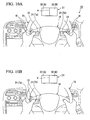
- the operation surfaces 22 of the separate touch pads 21 (touch pad Ta and touch pad Tb), which are associated with each of the plurality of (for example, two) display areas 32 (display area A and display area B) divided by the boundary ⁇ in the display screen 31, are disposed at positions which are deviated in the left side and the right side of the vehicle width direction from the center of the grip portion 16 in a neutral state of the steering wheel 15.
- the plurality of (for example, two) switches 41 are disposed at positions which are deviated in the left side and the right side in the vehicle width direction from each operation surface 22 on the grip portion 16 respectively.
- the operation surfaces 22 of the two touch pads 21 are disposed so as to be divided left and right on the grip portion 16 in a neutral state of the steering wheel 15.
- the operation surfaces 22 of the separate touch pads 21 (touch pad Ta and touch pad Tb), which are associated with each of the plurality of (for example, two) display areas 32 (display area A and display area B) divided by the boundary ⁇ in the display screen 31, may be disposed at the steering wheel 15 or other locations in the vicinity of the steering wheel 15.
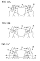
- the operation surfaces 22 of the two touch pads 21 are disposed so as to be symmetrical with respect to the center surface perpendicular to the vehicle width direction of the vehicle including the center of the steering wheel 15 at predetermined positions of the left side and right side on the steering wheel 15.
- the operation surfaces 22 of the two touch pads 21 are disposed so as to be symmetrical with respect to the center surface perpendicular to the vehicle width direction of the vehicle including the center of the steering wheel 15 at positions which are deviated in the left side and right side of the vehicle width direction from the center on the rear surface of the grip portion 16 in the neutral state of the steering wheel 15.
- the operation surfaces 22 of the two touch pads 21 are disposed so as to be symmetrical with respect to the center surface perpendicular to the vehicle width direction of the vehicle including the center of the steering wheel 15 in space portions 42 of the left side and right side of the steering wheel 15.
- the operation surfaces 22 of the two touch pads 21 are disposed so as to be symmetrical with respect to the center surface perpendicular to the vehicle width direction of the vehicle including the center of the steering wheel 15 at positions which are deviated in the left side and the right side of the vehicle width direction from the center of the grip portion 16 in the neutral state of the steering wheel 15, and the operation surface 22 of the other touch pad 21 is disposed at the center on the grip portion 16.
- the operation surfaces 22 of the two touch pads 21 are disposed at positions which are deviated in the upper side and lower side in the vertical direction from the center of the grip portion 16 in the neutral state of the steering wheel 15.
- the left side display area 32 (display area A) among the two display areas 32 is associated with the operation surface 22 of the touch pad 21 (touch pad Ta) that is disposed so as to deviate in the upper side of the vertical direction from the center of the grip portion 16 at the neutral state of the steering wheel 15.
- the right side display area 32 (display area B) among the two display areas 32 is associated with the operation surface 22 of the touch pad 21 (touch pad Tb) that is disposed so as to deviate in the lower side of the vertical direction from the center of the grip portion 16 at the neutral state of the steering wheel 15.
- the operation surfaces 22 of the separate touch pads 21 that are associated with each of the plurality of display areas 32 divided in the display screen 31 are disposed at different positions on the grip portion 16 in the neutral state of the steering wheel 15.
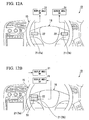
- the present invention is not limited to this, for example, as an eighth modification shown in FIGS. 12A and 12B , separate display screens 31 (display screen DA and display screen DB) that are associated with each of the plurality of touch pads 21 may be disposed inside the vehicle according to a disposition relationship of the touch pads 21 (touch pad Ta and touch pad Tb) that are disposed at the plurality of (for example, two) different positions.
- two display screens 31 are disposed at predetermined positions that are separated in the vehicle width direction on an instrument panel of the vehicle.
- one display screen 31 is associated with the operation surface 22 of one touch pad 21 (touch pad Ta)
- the other display screen 31 is associated with the operation surface 22 of the other touch pad 21 (touch pad Tb).
- the operation surfaces 22 of the two touch pads 21 are disposed so as to be adjacent in the vertical direction at a predetermined place that is deviated in one side (for example, left side) of the vehicle width direction from the center of the grip portion 16 in the neutral state of the steering wheel 15.
- two display screens 31 are disposed at predetermined positions that are separated in the vertical direction on the instrument panel of the vehicle.
- one display screen 31 is associated with the operation surface 22 of one touch pad 21 (touch pad Ta)
- the other display screen 31 is associated with the operation surface 22 of the other touch pad 21 (touch pad Tb).
- a vehicle input apparatus (10) includes a display screen (31) that displays a cursor that indicates an operation item with respect to a predetermined operation object, an input device that outputs signals according to a sliding operation using the fingers of an operator on an operation surface (22), and a display control portion (13) that controls movement of the cursor on the display screen (31) according to the signals that are output from the input device.
- the input device includes a plurality of operation surfaces (22) that are disposed at a plurality of different positions within a range which is reachable by the fingers of tan operator sitting in a driver's seat of the vehicle, the display screen (31) includes a plurality of display areas (32) that are divided according to the number of the plurality of operation surfaces (22), and each of the plurality of operation surfaces (22) is associated with a separate display area (32), and an operation range is set on the display screen (31) so that the cursor can only be moved within the range of the respective associated separate display area (32).
Landscapes
- Engineering & Computer Science (AREA)
- General Engineering & Computer Science (AREA)
- Theoretical Computer Science (AREA)
- Human Computer Interaction (AREA)
- Physics & Mathematics (AREA)
- General Physics & Mathematics (AREA)
- Chemical & Material Sciences (AREA)
- Combustion & Propulsion (AREA)
- Transportation (AREA)
- Mechanical Engineering (AREA)
- User Interface Of Digital Computer (AREA)
- Position Input By Displaying (AREA)
- Fittings On The Vehicle Exterior For Carrying Loads, And Devices For Holding Or Mounting Articles (AREA)
Claims (5)
- Fahrzeugeingabevorrichtung (10), welche aufweist:einen Anzeigeschirm (31), der einen Cursor (Q) anzeigt, der ein Bedienungselement (R) in Bezug auf ein vorbestimmtes Bedienungsobjekt angibt;eine Eingabevorrichtung (11), die gemäß einer Gleitbedienung unter Verwendung der Finger eines Bedieners auf einer Bedienungsoberfläche (22) Signale ausgibt; undeine Anzeigesteuereinheit (13), die eine Bewegung des Cursors auf dem Anzeigeschirm (31) gemäß den Signalen steuert, die von der Eingabevorrichtung (11) ausgegeben werden,wobei die Eingabevorrichtung (11) eine Mehrzahl der Bedienungsoberflächen (22) enthält, die an einer Mehrzahl von unterschiedlichen Positionen innerhalb eines Bereichs angeordnet sind, die mit den Fingern eines Bedieners erreichbar sind, der auf einem Fahrersitz des Fahrzeugs sitzt,dadurch gekennzeichnet, dassder Anzeigeschirm (31) eine Mehrzahl von Anzeigeflächen (32) enthält, die gemäß der Anzahl der Mehrzahl von Bedienungsoberflächen (22) aufgeteilt sind, undjeder der Mehrzahl von Bedienungsoberflächen (22) separate Anzeigeflächen (32) zugeordnet ist, und ein Bedienungsbereich auf dem Anzeigeschirm (31) so gesetzt ist, dass der Cursor (Q) nur innerhalb des Bereichs der jeweiligen zugeordneten separaten Bedienungsoberflächen (22) bewegt werden kann.
- Die Fahrzeugeingabevorrichtung nach Anspruch 1,
wobei die Anzeigefläche (32) und der Bedienungsbereich entsprechend einer absoluten Koordinate gesetzt sind, und
die Bedienungsbereiche, die benachbarten Anzeigeflächen (32) zugeordnet sind, so gesetzt sind, dass sie in der Nachbarschaft einer Grenze der benachbarten Anzeigeflächen (32) in Bezug auf die Mehrzahl von Anzeigeflächen (32) und die Mehrzahl von Bedienungsbereichen einander überlappen. - Die Fahrzeugeingabevorrichtung nach Anspruch 1,
wobei die Anzeigefläche (32) und der Bedienungsbereich entsprechend einer absoluten Koordinate gesetzt sind, und
der Cursor (Q) auf dem Anzeigeschirm (31) immer oder, wenn eine Gleitbedienung auf der Bedienungsoberfläche (22) durchgeführt wird, angezeigt wird, und der Cursor so angezeigt wird, dass er sich in einer Richtung gemäß der Richtung der Gleitbedienung bewegt, ausgehend von einer Position auf dem Anzeigeschirm (31) entsprechend der Bedienungsoberfläche (22), in der die Gleitbedienung durchgeführt wird, und der Startposition einer Gleitbedienung auf der Bedienungsoberfläche (22) unabhängig von der unmittelbar vorangehenden Position des Cursors auf dem Anzeigeschirm (31). - Die Fahrzeugeingabevorrichtung nach einem der Ansprüche 1 bis 3,
wobei der Anzeigeschirm (31) vor dem Fahrersitz angeordnet ist, mit einer angenähert rechteckigen Form konfiguriert ist, deren Längsrichtung der Fahrzeugbreitenrichtung eines Fahrzeugs entspricht, und in die Mehrzahl von Anzeigeflächen (32) durch eine Grenze unterteilt ist, die sich in Richtung senkrecht zur Längsrichtung erstreckt,
wobei jede der Mehrzahl von Bedienungsoberflächen (22) im Neutralzustand eines im Fahrzeug vorgesehenen Lenkrads (15) an vorbestimmten Orten an der linken und rechten Seite angeordnet ist, und
in Vorderansicht des Anzeigeschirms (31), eine linke Anzeigefläche unter einer Mehrzahl von Anzeigeflächen entsprechend dem Bedienungsbereich der Bedienungsoberfläche (22) gesetzt ist, die an der linken Seite des Lenkrads (15) angeordnet ist, und eine rechte Anzeigefläche unter der Mehrzahl von Anzeigeflächen entsprechend dem Bedienungsbereich der Bedienungsoberfläche (22) gesetzt ist, die an der rechten Seite des Lenkrads (15) angeordnet ist. - Die Fahrzeugeingabevorrichtung nach einem der Ansprüche 1 bis 4,
wobei das Bedienungselement (R) einen Zeicheneingaberahmen enthält, der bewirkt, dass das vorbestimmte Bedienungsobjekt durch Gleitbedienung eingegebene, handgeschriebene Zeichen erkennt,
der Cursor (Q) ein Zeiger ist, der, gemäß der in dem Zeicheneingaberahmen ausgeführten handschriftlichen Eingabe, einen Abschnitt des Zeichens angibt, und
wenn der Zeicheneingaberahmen auf dem Anzeigeschirm (31) angezeigt wird, der Bedienungsbereich so gesetzt wird, dass er einem Bereich des Zeicheneingaberahmens entspricht.
Applications Claiming Priority (1)
| Application Number | Priority Date | Filing Date | Title |
|---|---|---|---|
| JP2011238761A JP5452566B2 (ja) | 2011-10-31 | 2011-10-31 | 車両用入力装置 |
Publications (2)
| Publication Number | Publication Date |
|---|---|
| EP2586642A1 EP2586642A1 (de) | 2013-05-01 |
| EP2586642B1 true EP2586642B1 (de) | 2014-10-29 |
Family
ID=47358530
Family Applications (1)
| Application Number | Title | Priority Date | Filing Date |
|---|---|---|---|
| EP12190335.5A Not-in-force EP2586642B1 (de) | 2011-10-31 | 2012-10-29 | Fahrzeugeingabevorrichtung |
Country Status (4)
| Country | Link |
|---|---|
| US (1) | US9186994B2 (de) |
| EP (1) | EP2586642B1 (de) |
| JP (1) | JP5452566B2 (de) |
| CN (1) | CN103092402B (de) |
Cited By (1)
| Publication number | Priority date | Publication date | Assignee | Title |
|---|---|---|---|---|
| EP3486106A1 (de) * | 2017-11-20 | 2019-05-22 | Karma Automotive LLC | Fahrerschnittstellensystem |
Families Citing this family (93)
| Publication number | Priority date | Publication date | Assignee | Title |
|---|---|---|---|---|
| US8988399B2 (en) * | 2006-06-28 | 2015-03-24 | GM Global Technology Operations LLC | Vehicular interface including steering wheel control assembly |
| CN104350335B (zh) * | 2013-02-20 | 2017-10-20 | 松下电器(美国)知识产权公司 | 便携信息终端、便携信息终端的控制方法以及记录介质 |
| JP6136365B2 (ja) * | 2013-02-28 | 2017-05-31 | 日本精機株式会社 | 車両用操作装置 |
| JP5928397B2 (ja) * | 2013-04-03 | 2016-06-01 | 株式会社デンソー | 入力装置 |
| KR20140142824A (ko) * | 2013-06-05 | 2014-12-15 | 주식회사 코리아하이텍 | 차량용 계기판 시스템 |
| US20150002404A1 (en) * | 2013-06-27 | 2015-01-01 | GM Global Technology Operations LLC | Customizable steering wheel controls |
| US20160023604A1 (en) * | 2013-07-08 | 2016-01-28 | LightSpeed Automotive Technology | Head-Up Display Controller |
| DE102013013362A1 (de) * | 2013-08-09 | 2015-02-12 | Daimler Ag | Verfahren und Vorrichtung zum komprimierten Übertragen von Bewegungskoordinaten aufweisenden Signalen eines Bedienelements in einem Fahrzeug |
| JP2015033991A (ja) * | 2013-08-09 | 2015-02-19 | パイオニア株式会社 | インターフェースデバイス、インターフェースデバイス制御方法、及びインターフェースデバイス制御プログラム |
| KR101500130B1 (ko) * | 2013-09-02 | 2015-03-06 | 현대자동차주식회사 | 스티어링 휠에 설치된 차량용 제어장치 |
| CN103552517A (zh) * | 2013-11-20 | 2014-02-05 | 江南大学 | 一种驾驶员控制手势语言 |
| CN103631442A (zh) * | 2013-12-12 | 2014-03-12 | 惠州市华阳多媒体电子有限公司 | 一种抬头显示器的触摸控制系统 |
| EP2907730B1 (de) | 2014-01-29 | 2017-09-06 | Steering Solutions IP Holding Corporation | Erkennung von Händen am Lenkrad |
| WO2015134639A1 (en) * | 2014-03-04 | 2015-09-11 | Panasonic Automotive Systems Company Of America, Division Of Panasonic Corporation Of North America | Configurable touch screen lcd steering wheel controls |
| KR101575650B1 (ko) * | 2014-03-11 | 2015-12-08 | 현대자동차주식회사 | 단말기, 그를 가지는 차량 및 그 제어 방법 |
| KR101561917B1 (ko) * | 2014-04-10 | 2015-11-20 | 엘지전자 주식회사 | 차량 제어 장치 및 그 제어 방법 |
| JP6269343B2 (ja) * | 2014-06-23 | 2018-01-31 | トヨタ自動車株式会社 | 車両用操作装置 |
| DE102014118956A1 (de) * | 2014-12-18 | 2016-06-23 | Valeo Schalter Und Sensoren Gmbh | Verfahren zum Betreiben einer Bedienanordnung für ein Kraftfahrzeug mit Bereitstellen von zwei Bedienmodi für ein Bedienelement, Bedienanordnung sowie Kraftfahrzeug |
| DE102015106487A1 (de) * | 2015-04-28 | 2016-11-03 | Valeo Schalter Und Sensoren Gmbh | Bedienanordnung für ein Kraftfahrzeug mit Bedieneinrichtung in und/oder an einem Lenkradkranz, Kraftfahrzeug sowie Verfahren |
| US10351159B2 (en) | 2015-05-01 | 2019-07-16 | Steering Solutions Ip Holding Corporation | Retractable steering column with a radially projecting attachment |
| US10589774B2 (en) | 2015-05-01 | 2020-03-17 | Steering Solutions Ip Holding Corporation | Counter rotation steering wheel |
| CN106293431A (zh) * | 2015-05-26 | 2017-01-04 | 富泰华工业(深圳)有限公司 | 手写输入识别方法、系统与电子装置 |
| US9919724B2 (en) | 2015-05-29 | 2018-03-20 | Steering Solutions Ip Holding Corporation | Retractable steering column with manual retrieval |
| US11560169B2 (en) | 2015-06-11 | 2023-01-24 | Steering Solutions Ip Holding Corporation | Retractable steering column system and method |
| US10343706B2 (en) | 2015-06-11 | 2019-07-09 | Steering Solutions Ip Holding Corporation | Retractable steering column system, vehicle having the same, and method |
| DE102016110791A1 (de) | 2015-06-15 | 2016-12-15 | Steering Solutions Ip Holding Corporation | Gestensteuerung für ein einfahrbares Lenkrad |
| CN106256651B (zh) | 2015-06-16 | 2019-06-04 | 操纵技术Ip控股公司 | 可缩回转向柱组件及方法 |
| US9828016B2 (en) | 2015-06-24 | 2017-11-28 | Steering Solutions Ip Holding Corporation | Retractable steering column system, vehicle having the same, and method |
| US20160375931A1 (en) | 2015-06-25 | 2016-12-29 | Steering Solutions Ip Holding Corporation | Rotation control system for a steering wheel and method |
| DE102016111473A1 (de) | 2015-06-25 | 2016-12-29 | Steering Solutions Ip Holding Corporation | Stationäre lenkradbaugruppe und verfahren |
| US9944307B2 (en) | 2015-06-26 | 2018-04-17 | Steering Solutions Ip Holding Corporation | Steering assembly and method of monitoring a space within vehicle |
| US10112639B2 (en) | 2015-06-26 | 2018-10-30 | Steering Solutions Ip Holding Corporation | Vehicle steering arrangement and method of making same |
| US9845103B2 (en) | 2015-06-29 | 2017-12-19 | Steering Solutions Ip Holding Corporation | Steering arrangement |
| US9840271B2 (en) | 2015-06-29 | 2017-12-12 | Steering Solutions Ip Holding Corporation | Retractable steering column with rake limiter |
| WO2017001994A1 (en) * | 2015-06-29 | 2017-01-05 | Universita' Degli Studi Di Brescia | Gear shift device of a steering wheel group |
| KR101678094B1 (ko) | 2015-07-03 | 2016-11-23 | 현대자동차주식회사 | 차량, 및 그 제어방법 |
| US9849904B2 (en) | 2015-07-31 | 2017-12-26 | Steering Solutions Ip Holding Corporation | Retractable steering column with dual actuators |
| US10073612B1 (en) * | 2015-08-17 | 2018-09-11 | Bentley Systems, Incorporated | Fixed cursor input interface for a computer aided design application executing on a touch screen device |
| US9845106B2 (en) | 2015-08-31 | 2017-12-19 | Steering Solutions Ip Holding Corporation | Overload protection for belt drive mechanism |
| US10160472B2 (en) | 2015-10-20 | 2018-12-25 | Steering Solutions Ip Holding Corporation | Steering column with stationary hub |
| US9809155B2 (en) | 2015-10-27 | 2017-11-07 | Steering Solutions Ip Holding Corporation | Retractable steering column assembly having lever, vehicle having retractable steering column assembly, and method |
| KR102573705B1 (ko) * | 2015-11-24 | 2023-09-04 | 삼성디스플레이 주식회사 | 디스플레이 제어 시스템 |
| US10029725B2 (en) | 2015-12-03 | 2018-07-24 | Steering Solutions Ip Holding Corporation | Torque feedback system for a steer-by-wire vehicle, vehicle having steering column, and method of providing feedback in vehicle |
| US10322682B2 (en) | 2016-03-03 | 2019-06-18 | Steering Solutions Ip Holding Corporation | Steering wheel with keyboard |
| GB201604403D0 (en) * | 2016-03-15 | 2016-04-27 | Jaguar Land Rover Ltd | Method, apparatus and computer program for controlling a vehicle |
| US10496102B2 (en) | 2016-04-11 | 2019-12-03 | Steering Solutions Ip Holding Corporation | Steering system for autonomous vehicle |
| DE102017108692B4 (de) | 2016-04-25 | 2024-09-26 | Steering Solutions Ip Holding Corporation | Steuerung einer elektrischen Servolenkung unter Verwendung von Systemzustandsvorhersagen |
| US10351161B2 (en) | 2016-05-27 | 2019-07-16 | Steering Solutions Ip Holding Corporation | Steering column with manual retraction |
| CN107521547B (zh) | 2016-06-21 | 2020-03-10 | 操纵技术Ip控股公司 | 转向柱组件的自锁伸缩式致动器 |
| US10457313B2 (en) | 2016-06-28 | 2019-10-29 | Steering Solutions Ip Holding Corporation | ADAS wheel locking device |
| US10696308B2 (en) * | 2016-06-30 | 2020-06-30 | Intel Corporation | Road condition heads up display |
| US10363958B2 (en) | 2016-07-26 | 2019-07-30 | Steering Solutions Ip Holding Corporation | Electric power steering mode determination and transitioning |
| US10160477B2 (en) | 2016-08-01 | 2018-12-25 | Steering Solutions Ip Holding Corporation | Electric power steering column assembly |
| JP6597518B2 (ja) * | 2016-08-15 | 2019-10-30 | 株式会社デンソー | 情報処理装置及びプログラム |
| US10189496B2 (en) | 2016-08-22 | 2019-01-29 | Steering Solutions Ip Holding Corporation | Steering assembly having a telescope drive lock assembly |
| US10384708B2 (en) | 2016-09-12 | 2019-08-20 | Steering Solutions Ip Holding Corporation | Intermediate shaft assembly for steer-by-wire steering system |
| US10160473B2 (en) | 2016-09-13 | 2018-12-25 | Steering Solutions Ip Holding Corporation | Steering column decoupling system |
| US10144383B2 (en) | 2016-09-29 | 2018-12-04 | Steering Solutions Ip Holding Corporation | Steering wheel with video screen and airbag |
| US10399591B2 (en) | 2016-10-03 | 2019-09-03 | Steering Solutions Ip Holding Corporation | Steering compensation with grip sensing |
| US10239552B2 (en) | 2016-10-14 | 2019-03-26 | Steering Solutions Ip Holding Corporation | Rotation control assembly for a steering column |
| US10481602B2 (en) | 2016-10-17 | 2019-11-19 | Steering Solutions Ip Holding Corporation | Sensor fusion for autonomous driving transition control |
| DE102016119845B4 (de) * | 2016-10-18 | 2024-09-05 | Preh Gmbh | Eingabevorrichtung mit Fingerabdrucksensor und dem Fingerabdrucksensor zugeordnetem Kraftsensor |
| US10310605B2 (en) | 2016-11-15 | 2019-06-04 | Steering Solutions Ip Holding Corporation | Haptic feedback for steering system controls |
| US10421475B2 (en) | 2016-11-15 | 2019-09-24 | Steering Solutions Ip Holding Corporation | Electric actuator mechanism for retractable steering column assembly with manual override |
| JP6508173B2 (ja) * | 2016-11-25 | 2019-05-08 | トヨタ自動車株式会社 | 車両用表示装置 |
| US9862403B1 (en) | 2016-11-29 | 2018-01-09 | Steering Solutions Ip Holding Corporation | Manually retractable steering column assembly for autonomous vehicle |
| US10351160B2 (en) | 2016-11-30 | 2019-07-16 | Steering Solutions Ip Holding Corporation | Steering column assembly having a sensor assembly |
| CN108153427B (zh) * | 2016-12-02 | 2021-04-20 | 上海博泰悦臻电子设备制造有限公司 | 一种键盘布局方法、系统及一种车机 |
| US10780915B2 (en) | 2016-12-07 | 2020-09-22 | Steering Solutions Ip Holding Corporation | Vehicle steering system having a user experience based automated driving to manual driving transition system and method |
| KR102726187B1 (ko) * | 2016-12-16 | 2024-11-06 | 현대자동차주식회사 | 차량, 및 그 제어방법 |
| JP6528790B2 (ja) * | 2017-01-23 | 2019-06-12 | トヨタ自動車株式会社 | 車両用入力装置、及び、車両用入力装置の制御方法 |
| US10370022B2 (en) | 2017-02-13 | 2019-08-06 | Steering Solutions Ip Holding Corporation | Steering column assembly for autonomous vehicle |
| US10385930B2 (en) | 2017-02-21 | 2019-08-20 | Steering Solutions Ip Holding Corporation | Ball coupling assembly for steering column assembly |
| US10449927B2 (en) | 2017-04-13 | 2019-10-22 | Steering Solutions Ip Holding Corporation | Steering system having anti-theft capabilities |
| JP6948191B2 (ja) * | 2017-09-01 | 2021-10-13 | 株式会社東海理化電機製作所 | タッチパッド |
| FR3070636B1 (fr) * | 2017-09-05 | 2019-08-23 | Continental Automotive France | Palette tactile a effet optique sur volant de conduite pour detection de doigt |
| DE102017126438A1 (de) * | 2017-11-10 | 2019-05-16 | U-Shin Deutschland Zugangssysteme Gmbh | Lenkrad für ein Kraftfahrzeug |
| WO2019111515A1 (ja) * | 2017-12-08 | 2019-06-13 | パナソニックIpマネジメント株式会社 | 入力装置、及び、入力方法 |
| US10875566B2 (en) | 2018-03-22 | 2020-12-29 | Steering Solutions Ip Holding Corporation | Stow release assembly for a manually adjustable steering column assembly |
| KR102529458B1 (ko) * | 2018-03-23 | 2023-05-08 | 현대자동차주식회사 | 터치 컨트롤 기반 스티어링 휠 조작 장치 및 방법 |
| CN108674325A (zh) * | 2018-03-30 | 2018-10-19 | 斑马网络技术有限公司 | 显控方向盘及其显控系统和方法 |
| US10974756B2 (en) | 2018-07-31 | 2021-04-13 | Steering Solutions Ip Holding Corporation | Clutch device latching system and method |
| JP7192413B2 (ja) * | 2018-11-06 | 2022-12-20 | トヨタ自動車株式会社 | 車両用操作装置 |
| KR20200068089A (ko) * | 2018-11-28 | 2020-06-15 | 전자부품연구원 | 차량용 증강현실 디스플레이를 위한 직관적 상호작용 방법 및 시스템 |
| KR102212794B1 (ko) | 2018-11-30 | 2021-02-05 | 엘지전자 주식회사 | 차량 제어장치 및 차량 제어방법 |
| US11110798B2 (en) * | 2019-01-31 | 2021-09-07 | Toyota Motor Engineering & Manufacturing North America, Inc. | Multi-function vehicle input apparatuses with operational buttons for vehicle systems control and methods incorporating the same |
| JP7197674B2 (ja) * | 2019-02-27 | 2022-12-27 | 本田技研工業株式会社 | 操舵操作子 |
| CN111660808A (zh) * | 2020-06-05 | 2020-09-15 | 禾多科技(北京)有限公司 | 车载人机交互界面 |
| DE102020119640A1 (de) * | 2020-07-24 | 2022-01-27 | Bayerische Motoren Werke Aktiengesellschaft | Steuerung von Anzeigebereichen |
| CN112406898A (zh) * | 2020-11-20 | 2021-02-26 | 上海仙塔智能科技有限公司 | 一种车机操控装置、车机操控方法及计算机存储介质 |
| US11816307B1 (en) * | 2022-05-06 | 2023-11-14 | Honda Motor Co., Ltd. | Method for providing service of configuring UI on a display of an in-vehicle infotainment device and UI configuration server using the same |
| CN218703440U (zh) * | 2022-10-31 | 2023-03-24 | 比亚迪股份有限公司 | 方向盘、智能驾驶控制装置以及车辆 |
| CN120024286A (zh) * | 2023-11-22 | 2025-05-23 | 富泰京精密电子(烟台)有限公司 | 车用显示屏归位方法、车辆、电子设备和计算机存储介质 |
Family Cites Families (15)
| Publication number | Priority date | Publication date | Assignee | Title |
|---|---|---|---|---|
| US6373472B1 (en) * | 1995-10-13 | 2002-04-16 | Silviu Palalau | Driver control interface system |
| US5881169A (en) * | 1996-09-13 | 1999-03-09 | Ericsson Inc. | Apparatus and method for presenting and gathering text entries in a pen-based input device |
| JP4132150B2 (ja) | 1997-10-06 | 2008-08-13 | 富士重工業株式会社 | 車載機器の集中制御装置 |
| JP4294122B2 (ja) * | 1998-06-23 | 2009-07-08 | アルプス電気株式会社 | 座標入力装置 |
| US6784869B1 (en) * | 2000-11-15 | 2004-08-31 | The Boeing Company | Cursor and display management system for multi-function control and display system |
| JP2002312122A (ja) * | 2001-04-12 | 2002-10-25 | Sharp Corp | 入力表示装置及び該装置の入力枠表示方法 |
| US20060227065A1 (en) | 2005-04-08 | 2006-10-12 | Matsushita Electric Industrial Co. Ltd. | Human machine interface system for automotive application |
| KR100954594B1 (ko) * | 2007-02-23 | 2010-04-26 | (주)티피다시아이 | 디지털 기기에 사용되는 포인팅장치를 이용한 가상키보드입력시스템 |
| JP2009298285A (ja) * | 2008-06-12 | 2009-12-24 | Tokai Rika Co Ltd | 入力装置 |
| US20100188343A1 (en) * | 2009-01-29 | 2010-07-29 | Edward William Bach | Vehicular control system comprising touch pad and vehicles and methods |
| US8406961B2 (en) * | 2009-04-16 | 2013-03-26 | Panasonic Corporation | Reconfigurable vehicle user interface system |
| US8188969B2 (en) * | 2009-06-26 | 2012-05-29 | Panasonic Corporation | Dual pointer management method using cooperating input sources and efficient dynamic coordinate remapping |
| US9551590B2 (en) | 2009-08-28 | 2017-01-24 | Robert Bosch Gmbh | Gesture-based information and command entry for motor vehicle |
| WO2011096166A1 (ja) * | 2010-02-03 | 2011-08-11 | パナソニック株式会社 | 表示制御装置、表示制御方法およびタッチパッド入力システム |
| US8547354B2 (en) * | 2010-11-05 | 2013-10-01 | Apple Inc. | Device, method, and graphical user interface for manipulating soft keyboards |
-
2011
- 2011-10-31 JP JP2011238761A patent/JP5452566B2/ja not_active Expired - Fee Related
-
2012
- 2012-10-26 US US13/661,403 patent/US9186994B2/en not_active Expired - Fee Related
- 2012-10-29 CN CN201210431439.0A patent/CN103092402B/zh not_active Expired - Fee Related
- 2012-10-29 EP EP12190335.5A patent/EP2586642B1/de not_active Not-in-force
Cited By (2)
| Publication number | Priority date | Publication date | Assignee | Title |
|---|---|---|---|---|
| EP3486106A1 (de) * | 2017-11-20 | 2019-05-22 | Karma Automotive LLC | Fahrerschnittstellensystem |
| CN109808599A (zh) * | 2017-11-20 | 2019-05-28 | 凯莱汽车公司 | 驾驶员界面系统 |
Also Published As
| Publication number | Publication date |
|---|---|
| JP5452566B2 (ja) | 2014-03-26 |
| EP2586642A1 (de) | 2013-05-01 |
| US9186994B2 (en) | 2015-11-17 |
| CN103092402B (zh) | 2016-04-06 |
| JP2013097513A (ja) | 2013-05-20 |
| CN103092402A (zh) | 2013-05-08 |
| US20130106693A1 (en) | 2013-05-02 |
Similar Documents
| Publication | Publication Date | Title |
|---|---|---|
| EP2586642B1 (de) | Fahrzeugeingabevorrichtung | |
| US8773394B2 (en) | Vehicular operating device | |
| JP5641001B2 (ja) | 表示制御装置および表示システム | |
| JP4960127B2 (ja) | 操作デバイス | |
| US9207856B2 (en) | Vehicula touch input device with determination of straight line gesture | |
| EP2295277A1 (de) | Fahrzeugbedienersteuerungseingabehilfe | |
| JP6035828B2 (ja) | 表示操作装置および表示システム | |
| CN105683869B (zh) | 能够无按键操作的操作装置 | |
| US9965061B2 (en) | Input device and vehicle | |
| US20130201126A1 (en) | Input device | |
| JP2012210874A (ja) | 車載入力装置 | |
| US20160154488A1 (en) | Integrated controller system for vehicle | |
| JP2006264615A (ja) | 車両用表示装置 | |
| US20180232115A1 (en) | In-vehicle input device and in-vehicle input device control method | |
| WO2015122259A1 (ja) | 入力方法、及び入力装置 | |
| WO2015129189A1 (ja) | 機器操作装置 | |
| JP6304095B2 (ja) | 電子機器 | |
| US20170052612A1 (en) | Display operating system | |
| JP7001368B2 (ja) | 操作装置 | |
| JP6451887B2 (ja) | 電子機器 | |
| JP5460890B2 (ja) | 入力操作装置 | |
| WO2016031148A1 (ja) | 車両用タッチパッドおよび車両用入力インターフェイス | |
| WO2016087902A1 (en) | Operating device for a vehicle, in particular a passenger vehicle; as well as method for operating such an operating device | |
| JP2016141171A (ja) | 車両用空調装置の操作入力装置 | |
| JP2013105448A (ja) | 車両用入力装置 |
Legal Events
| Date | Code | Title | Description |
|---|---|---|---|
| PUAI | Public reference made under article 153(3) epc to a published international application that has entered the european phase |
Free format text: ORIGINAL CODE: 0009012 |
|
| 17P | Request for examination filed |
Effective date: 20121029 |
|
| AK | Designated contracting states |
Kind code of ref document: A1 Designated state(s): AL AT BE BG CH CY CZ DE DK EE ES FI FR GB GR HR HU IE IS IT LI LT LU LV MC MK MT NL NO PL PT RO RS SE SI SK SM TR |
|
| AX | Request for extension of the european patent |
Extension state: BA ME |
|
| GRAP | Despatch of communication of intention to grant a patent |
Free format text: ORIGINAL CODE: EPIDOSNIGR1 |
|
| INTG | Intention to grant announced |
Effective date: 20140411 |
|
| GRAS | Grant fee paid |
Free format text: ORIGINAL CODE: EPIDOSNIGR3 |
|
| GRAA | (expected) grant |
Free format text: ORIGINAL CODE: 0009210 |
|
| AK | Designated contracting states |
Kind code of ref document: B1 Designated state(s): AL AT BE BG CH CY CZ DE DK EE ES FI FR GB GR HR HU IE IS IT LI LT LU LV MC MK MT NL NO PL PT RO RS SE SI SK SM TR |
|
| REG | Reference to a national code |
Ref country code: GB Ref legal event code: FG4D |
|
| REG | Reference to a national code |
Ref country code: CH Ref legal event code: EP |
|
| REG | Reference to a national code |
Ref country code: AT Ref legal event code: REF Ref document number: 693390 Country of ref document: AT Kind code of ref document: T Effective date: 20141115 |
|
| REG | Reference to a national code |
Ref country code: IE Ref legal event code: FG4D |
|
| REG | Reference to a national code |
Ref country code: DE Ref legal event code: R096 Ref document number: 602012003568 Country of ref document: DE Effective date: 20141204 |
|
| REG | Reference to a national code |
Ref country code: AT Ref legal event code: MK05 Ref document number: 693390 Country of ref document: AT Kind code of ref document: T Effective date: 20141029 |
|
| REG | Reference to a national code |
Ref country code: NL Ref legal event code: VDEP Effective date: 20141029 |
|
| REG | Reference to a national code |
Ref country code: LT Ref legal event code: MG4D |
|
| PG25 | Lapsed in a contracting state [announced via postgrant information from national office to epo] |
Ref country code: PT Free format text: LAPSE BECAUSE OF FAILURE TO SUBMIT A TRANSLATION OF THE DESCRIPTION OR TO PAY THE FEE WITHIN THE PRESCRIBED TIME-LIMIT Effective date: 20150302 Ref country code: IS Free format text: LAPSE BECAUSE OF FAILURE TO SUBMIT A TRANSLATION OF THE DESCRIPTION OR TO PAY THE FEE WITHIN THE PRESCRIBED TIME-LIMIT Effective date: 20150228 Ref country code: ES Free format text: LAPSE BECAUSE OF FAILURE TO SUBMIT A TRANSLATION OF THE DESCRIPTION OR TO PAY THE FEE WITHIN THE PRESCRIBED TIME-LIMIT Effective date: 20141029 Ref country code: NL Free format text: LAPSE BECAUSE OF FAILURE TO SUBMIT A TRANSLATION OF THE DESCRIPTION OR TO PAY THE FEE WITHIN THE PRESCRIBED TIME-LIMIT Effective date: 20141029 Ref country code: FI Free format text: LAPSE BECAUSE OF FAILURE TO SUBMIT A TRANSLATION OF THE DESCRIPTION OR TO PAY THE FEE WITHIN THE PRESCRIBED TIME-LIMIT Effective date: 20141029 Ref country code: LT Free format text: LAPSE BECAUSE OF FAILURE TO SUBMIT A TRANSLATION OF THE DESCRIPTION OR TO PAY THE FEE WITHIN THE PRESCRIBED TIME-LIMIT Effective date: 20141029 Ref country code: NO Free format text: LAPSE BECAUSE OF FAILURE TO SUBMIT A TRANSLATION OF THE DESCRIPTION OR TO PAY THE FEE WITHIN THE PRESCRIBED TIME-LIMIT Effective date: 20150129 |
|
| PG25 | Lapsed in a contracting state [announced via postgrant information from national office to epo] |
Ref country code: AT Free format text: LAPSE BECAUSE OF FAILURE TO SUBMIT A TRANSLATION OF THE DESCRIPTION OR TO PAY THE FEE WITHIN THE PRESCRIBED TIME-LIMIT Effective date: 20141029 Ref country code: SE Free format text: LAPSE BECAUSE OF FAILURE TO SUBMIT A TRANSLATION OF THE DESCRIPTION OR TO PAY THE FEE WITHIN THE PRESCRIBED TIME-LIMIT Effective date: 20141029 Ref country code: CY Free format text: LAPSE BECAUSE OF FAILURE TO SUBMIT A TRANSLATION OF THE DESCRIPTION OR TO PAY THE FEE WITHIN THE PRESCRIBED TIME-LIMIT Effective date: 20141029 Ref country code: HR Free format text: LAPSE BECAUSE OF FAILURE TO SUBMIT A TRANSLATION OF THE DESCRIPTION OR TO PAY THE FEE WITHIN THE PRESCRIBED TIME-LIMIT Effective date: 20141029 Ref country code: PL Free format text: LAPSE BECAUSE OF FAILURE TO SUBMIT A TRANSLATION OF THE DESCRIPTION OR TO PAY THE FEE WITHIN THE PRESCRIBED TIME-LIMIT Effective date: 20141029 Ref country code: GR Free format text: LAPSE BECAUSE OF FAILURE TO SUBMIT A TRANSLATION OF THE DESCRIPTION OR TO PAY THE FEE WITHIN THE PRESCRIBED TIME-LIMIT Effective date: 20150130 Ref country code: RS Free format text: LAPSE BECAUSE OF FAILURE TO SUBMIT A TRANSLATION OF THE DESCRIPTION OR TO PAY THE FEE WITHIN THE PRESCRIBED TIME-LIMIT Effective date: 20141029 Ref country code: LV Free format text: LAPSE BECAUSE OF FAILURE TO SUBMIT A TRANSLATION OF THE DESCRIPTION OR TO PAY THE FEE WITHIN THE PRESCRIBED TIME-LIMIT Effective date: 20141029 |
|
| PG25 | Lapsed in a contracting state [announced via postgrant information from national office to epo] |
Ref country code: BE Free format text: LAPSE BECAUSE OF NON-PAYMENT OF DUE FEES Effective date: 20141031 |
|
| REG | Reference to a national code |
Ref country code: IE Ref legal event code: MM4A |
|
| REG | Reference to a national code |
Ref country code: DE Ref legal event code: R097 Ref document number: 602012003568 Country of ref document: DE |
|
| PG25 | Lapsed in a contracting state [announced via postgrant information from national office to epo] |
Ref country code: DK Free format text: LAPSE BECAUSE OF FAILURE TO SUBMIT A TRANSLATION OF THE DESCRIPTION OR TO PAY THE FEE WITHIN THE PRESCRIBED TIME-LIMIT Effective date: 20141029 Ref country code: EE Free format text: LAPSE BECAUSE OF FAILURE TO SUBMIT A TRANSLATION OF THE DESCRIPTION OR TO PAY THE FEE WITHIN THE PRESCRIBED TIME-LIMIT Effective date: 20141029 Ref country code: RO Free format text: LAPSE BECAUSE OF FAILURE TO SUBMIT A TRANSLATION OF THE DESCRIPTION OR TO PAY THE FEE WITHIN THE PRESCRIBED TIME-LIMIT Effective date: 20141029 Ref country code: SK Free format text: LAPSE BECAUSE OF FAILURE TO SUBMIT A TRANSLATION OF THE DESCRIPTION OR TO PAY THE FEE WITHIN THE PRESCRIBED TIME-LIMIT Effective date: 20141029 Ref country code: CZ Free format text: LAPSE BECAUSE OF FAILURE TO SUBMIT A TRANSLATION OF THE DESCRIPTION OR TO PAY THE FEE WITHIN THE PRESCRIBED TIME-LIMIT Effective date: 20141029 |
|
| PG25 | Lapsed in a contracting state [announced via postgrant information from national office to epo] |
Ref country code: IT Free format text: LAPSE BECAUSE OF FAILURE TO SUBMIT A TRANSLATION OF THE DESCRIPTION OR TO PAY THE FEE WITHIN THE PRESCRIBED TIME-LIMIT Effective date: 20141029 |
|
| PLBE | No opposition filed within time limit |
Free format text: ORIGINAL CODE: 0009261 |
|
| STAA | Information on the status of an ep patent application or granted ep patent |
Free format text: STATUS: NO OPPOSITION FILED WITHIN TIME LIMIT |
|
| 26N | No opposition filed |
Effective date: 20150730 |
|
| REG | Reference to a national code |
Ref country code: FR Ref legal event code: PLFP Year of fee payment: 4 |
|
| PG25 | Lapsed in a contracting state [announced via postgrant information from national office to epo] |
Ref country code: IE Free format text: LAPSE BECAUSE OF NON-PAYMENT OF DUE FEES Effective date: 20141029 |
|
| PG25 | Lapsed in a contracting state [announced via postgrant information from national office to epo] |
Ref country code: SI Free format text: LAPSE BECAUSE OF FAILURE TO SUBMIT A TRANSLATION OF THE DESCRIPTION OR TO PAY THE FEE WITHIN THE PRESCRIBED TIME-LIMIT Effective date: 20141029 |
|
| PGFP | Annual fee paid to national office [announced via postgrant information from national office to epo] |
Ref country code: FR Payment date: 20151023 Year of fee payment: 4 |
|
| REG | Reference to a national code |
Ref country code: CH Ref legal event code: PL |
|
| PG25 | Lapsed in a contracting state [announced via postgrant information from national office to epo] |
Ref country code: BG Free format text: LAPSE BECAUSE OF FAILURE TO SUBMIT A TRANSLATION OF THE DESCRIPTION OR TO PAY THE FEE WITHIN THE PRESCRIBED TIME-LIMIT Effective date: 20141029 Ref country code: MC Free format text: LAPSE BECAUSE OF FAILURE TO SUBMIT A TRANSLATION OF THE DESCRIPTION OR TO PAY THE FEE WITHIN THE PRESCRIBED TIME-LIMIT Effective date: 20141029 |
|
| PG25 | Lapsed in a contracting state [announced via postgrant information from national office to epo] |
Ref country code: MT Free format text: LAPSE BECAUSE OF FAILURE TO SUBMIT A TRANSLATION OF THE DESCRIPTION OR TO PAY THE FEE WITHIN THE PRESCRIBED TIME-LIMIT Effective date: 20141029 Ref country code: CH Free format text: LAPSE BECAUSE OF NON-PAYMENT OF DUE FEES Effective date: 20151031 Ref country code: HU Free format text: LAPSE BECAUSE OF FAILURE TO SUBMIT A TRANSLATION OF THE DESCRIPTION OR TO PAY THE FEE WITHIN THE PRESCRIBED TIME-LIMIT; INVALID AB INITIO Effective date: 20121029 Ref country code: LI Free format text: LAPSE BECAUSE OF NON-PAYMENT OF DUE FEES Effective date: 20151031 Ref country code: LU Free format text: LAPSE BECAUSE OF NON-PAYMENT OF DUE FEES Effective date: 20141029 Ref country code: TR Free format text: LAPSE BECAUSE OF FAILURE TO SUBMIT A TRANSLATION OF THE DESCRIPTION OR TO PAY THE FEE WITHIN THE PRESCRIBED TIME-LIMIT Effective date: 20141029 |
|
| PGFP | Annual fee paid to national office [announced via postgrant information from national office to epo] |
Ref country code: DE Payment date: 20161025 Year of fee payment: 5 |
|
| PG25 | Lapsed in a contracting state [announced via postgrant information from national office to epo] |
Ref country code: SM Free format text: LAPSE BECAUSE OF FAILURE TO SUBMIT A TRANSLATION OF THE DESCRIPTION OR TO PAY THE FEE WITHIN THE PRESCRIBED TIME-LIMIT Effective date: 20141029 |
|
| GBPC | Gb: european patent ceased through non-payment of renewal fee |
Effective date: 20161029 |
|
| REG | Reference to a national code |
Ref country code: FR Ref legal event code: ST Effective date: 20170630 |
|
| PG25 | Lapsed in a contracting state [announced via postgrant information from national office to epo] |
Ref country code: FR Free format text: LAPSE BECAUSE OF NON-PAYMENT OF DUE FEES Effective date: 20161102 Ref country code: GB Free format text: LAPSE BECAUSE OF NON-PAYMENT OF DUE FEES Effective date: 20161029 |
|
| REG | Reference to a national code |
Ref country code: DE Ref legal event code: R119 Ref document number: 602012003568 Country of ref document: DE |
|
| PG25 | Lapsed in a contracting state [announced via postgrant information from national office to epo] |
Ref country code: MK Free format text: LAPSE BECAUSE OF FAILURE TO SUBMIT A TRANSLATION OF THE DESCRIPTION OR TO PAY THE FEE WITHIN THE PRESCRIBED TIME-LIMIT Effective date: 20141029 |
|
| PG25 | Lapsed in a contracting state [announced via postgrant information from national office to epo] |
Ref country code: DE Free format text: LAPSE BECAUSE OF NON-PAYMENT OF DUE FEES Effective date: 20180501 |
|
| PG25 | Lapsed in a contracting state [announced via postgrant information from national office to epo] |
Ref country code: AL Free format text: LAPSE BECAUSE OF FAILURE TO SUBMIT A TRANSLATION OF THE DESCRIPTION OR TO PAY THE FEE WITHIN THE PRESCRIBED TIME-LIMIT Effective date: 20141029 |