EP2581334B1 - Fall Protection for Elevators - Google Patents
Fall Protection for Elevators Download PDFInfo
- Publication number
- EP2581334B1 EP2581334B1 EP12401205.5A EP12401205A EP2581334B1 EP 2581334 B1 EP2581334 B1 EP 2581334B1 EP 12401205 A EP12401205 A EP 12401205A EP 2581334 B1 EP2581334 B1 EP 2581334B1
- Authority
- EP
- European Patent Office
- Prior art keywords
- fall protector
- rollable material
- fall protection
- fall
- car
- Prior art date
- Legal status (The legal status is an assumption and is not a legal conclusion. Google has not performed a legal analysis and makes no representation as to the accuracy of the status listed.)
- Active
Links
- 239000000463 material Substances 0.000 claims description 49
- 239000004753 textile Substances 0.000 claims description 10
- 238000012544 monitoring process Methods 0.000 claims description 6
- 239000002184 metal Substances 0.000 claims description 3
- 239000004744 fabric Substances 0.000 claims description 2
- 239000010985 leather Substances 0.000 claims description 2
- 239000004033 plastic Substances 0.000 claims description 2
- 229920003023 plastic Polymers 0.000 claims description 2
- 239000005060 rubber Substances 0.000 claims description 2
- 230000001012 protector Effects 0.000 claims 16
- 238000009434 installation Methods 0.000 description 6
- 230000004913 activation Effects 0.000 description 5
- 230000006378 damage Effects 0.000 description 5
- 238000005096 rolling process Methods 0.000 description 5
- 208000027418 Wounds and injury Diseases 0.000 description 3
- 230000006835 compression Effects 0.000 description 3
- 238000007906 compression Methods 0.000 description 3
- 208000014674 injury Diseases 0.000 description 3
- 238000012423 maintenance Methods 0.000 description 3
- 230000003213 activating effect Effects 0.000 description 2
- 239000013013 elastic material Substances 0.000 description 2
- 230000005484 gravity Effects 0.000 description 2
- 238000004519 manufacturing process Methods 0.000 description 2
- 230000000087 stabilizing effect Effects 0.000 description 2
- RNFJDJUURJAICM-UHFFFAOYSA-N 2,2,4,4,6,6-hexaphenoxy-1,3,5-triaza-2$l^{5},4$l^{5},6$l^{5}-triphosphacyclohexa-1,3,5-triene Chemical compound N=1P(OC=2C=CC=CC=2)(OC=2C=CC=CC=2)=NP(OC=2C=CC=CC=2)(OC=2C=CC=CC=2)=NP=1(OC=1C=CC=CC=1)OC1=CC=CC=C1 RNFJDJUURJAICM-UHFFFAOYSA-N 0.000 description 1
- 210000001015 abdomen Anatomy 0.000 description 1
- 238000010276 construction Methods 0.000 description 1
- 230000007812 deficiency Effects 0.000 description 1
- 230000001419 dependent effect Effects 0.000 description 1
- 238000001514 detection method Methods 0.000 description 1
- 230000005611 electricity Effects 0.000 description 1
- 239000003063 flame retardant Substances 0.000 description 1
- 239000011521 glass Substances 0.000 description 1
- 238000000034 method Methods 0.000 description 1
- 230000001681 protective effect Effects 0.000 description 1
- 238000010008 shearing Methods 0.000 description 1
- -1 strip Substances 0.000 description 1
- 210000003371 toe Anatomy 0.000 description 1
- 230000001960 triggered effect Effects 0.000 description 1
Images


Classifications
-
- B—PERFORMING OPERATIONS; TRANSPORTING
- B66—HOISTING; LIFTING; HAULING
- B66B—ELEVATORS; ESCALATORS OR MOVING WALKWAYS
- B66B13/00—Doors, gates, or other apparatus controlling access to, or exit from, cages or lift well landings
- B66B13/24—Safety devices in passenger lifts, not otherwise provided for, for preventing trapping of passengers
- B66B13/28—Safety devices in passenger lifts, not otherwise provided for, for preventing trapping of passengers between car or cage and wells
- B66B13/285—Toe guards or apron devices
-
- B—PERFORMING OPERATIONS; TRANSPORTING
- B66—HOISTING; LIFTING; HAULING
- B66B—ELEVATORS; ESCALATORS OR MOVING WALKWAYS
- B66B5/00—Applications of checking, fault-correcting, or safety devices in elevators
- B66B5/0043—Devices enhancing safety during maintenance
- B66B5/005—Safety of maintenance personnel
- B66B5/0081—Safety of maintenance personnel by preventing falling by means of safety fences or handrails, being operable or not, mounted on top of the elevator car
Definitions
- the invention relates to a roll-up fall protection for elevator systems, which is used instead of conventional cabin door aprons in the area of the car door sill.
- a cabin door apron in elevators is, according to European elevator standards, a vertical, fixed piece of 750mm length, mounted flush with the car door sill, pointing vertically downwards, to prevent persons from falling into the hoistway when the passenger is cleared.
- a disadvantage of the telescopic apron for a lift car after EP 2 042 463 B1 is that for reasons of stability, complexity, and space requirements, it can be at most four levels. Including the underpass and buffer stroke results in a minimum pit pit depth of 400mm. Telescopic aprons have the further disadvantage that they automatically when entering the lowest stop be brought together and thereby cause noise, or they are activated only in the event of personal exemption by the elevator attendant. This involves the risk that this crashes even in the elevator shaft, before the apron is extended. Furthermore, there is a risk of crushing during manual extension of the apron.
- the roll-up apron If the roll-up apron is installed slightly offset to the rear of the cabin and before a fixed apron attached, it must have a chamfer because of the risk of crushing in the unlocking zone. The rollable material is then no longer flush with the front edge of the threshold.
- DE 10 2006 045 499 A1 describes a car apron with safety function. It describes a car-mounted protection device that can be moved from an active to an inactive position. In order to avoid accidental movement into the inactive position, the protective device can be locked in the active position.
- the protection device arranged under the car can have a car apron element on at least one access side of the car.
- Foldable cabin door aprons are off DE 10 2008 038 408 A1 .
- DE 20 313 911 U1 and EP 2 138 443 A1 known.
- DE 20 313 911 U1 and EP 2 138 443 A1 Used slat cross profiles, which are guided between extendable supports. These slat cross profiles can not be rolled up as they are attached to the columns. Rather, they are strung in the active state in the vertical direction one after the other. This results in an overall height depending on the thickness and the number of transverse profiles.
- the inactive apron thus has a minimum space requirement (installation height) below the cabin door apron, which corresponds to this total height.
- installation height installation height
- DE 10 2008 038 408 A1 neither cross profiles nor a locking device are provided for keeping the roll-up material, thereby resulting in the same disadvantages as in DE 10 2008 038 409 A1 result.
- the elastic material in the inactive state is stacked one behind the other. This layering inevitably takes place directly below the car door sill. With this arrangement, it can not be ruled out that the individual layers fold in the direction of the shaft door. This is unfavorable because the elastic material stuck in the elevator ride on the shaft doors and can be damaged.
- aprons are activated only when a shaft door is opened with a Entriegelungsdreikant. For manual systems, activation can only be done manually by the lift attendant.
- the inactive aprons are activated when the car is unintentionally moved out of the station. Inadvertent movement of the car from the stop is a movement of the car with the door open away from the stop, not initiated by the controller within the unlocking zone. With inactive aprons, there is a risk that the remaining apron length is too short and persons who get rid of themselves in this situation can fall into the elevator shaft.
- FR 2 891 820 A1 describes an elevator with a safety device, with the help of a maintenance of elevator components in the elevator shaft is to be made possible from the cab roof.
- the safety device arranged on the car roof is a railing consisting of vertically movable rods which can be moved between a lowered and an upper position, wherein a flexible film can be rolled up and fills the space between the car roof and the rods.
- This device has nothing in common with a cabin door apron. In order to overcome gravity, this device requires at least one electric motor or a spring element in order to bring the device into the active position.
- the object of the invention is to provide a fall protection for elevator systems with low shaft pit depths, which solves the problems mentioned and thus provides a much greater level of security.
- the fall protection should avoid the listed risk of falling and injury and manage with a much smaller installation height.
- the scope of fall protection should be as large as possible so that it can be used universally for a wide variety of elevator types.
- the fall protection according to the invention for elevator installations with a movable elevator car, in which rollable material can be rolled up and down by at least one retractor, is characterized in that the loose end of the rollable material is fastened in the area of the elevator car and the retractor with the rollable material of the Elevator car is arranged away movable.
- the present invention solves the aforementioned problems by realizing a very compact fall protection, which is installed as a replacement of conventional cabin door aprons in the area of the car door sills.
- the rollable material is deflected by the retractor by means of a deflection device so that the rollable material after the deflection in the activated state in the vertical direction.
- the space requirement under the car door sill can thereby be further reduced by only a relatively small pulley is provided instead of a relatively large retractor.
- the retractor can be located behind or above the deepest exit point where it does not bother. By this arrangement it is achieved that the rollable material always flush with the car door sill edge or the cabin roof outer edge.
- a receiving profile may be attached, which allows a quick and easy attachment in the cabin door. The result is a flush finish without protrusions or slots. An injury risk can be avoided.
- the fall protection can be performed in an open design without housing.
- At least one monitoring switch or a monitoring sensor is used, which detects the position of the fall protection (active or inactive).
- the controller used evaluates this information and prevents the elevator can go into normal operation with extended (active) fall protection. This prevents that the elevator moves the extended and arrested fall protection against the pit floor or against the shaft ceiling.
- the control may be the elevator control or a separate (self-sufficient) control unit.
- the rollable material consists of textiles, plastics, strip, leather, rubber or metal mesh or other full-surface or net-like materials that can be easily rolled up and unrolled and at the same time are flame retardant.
- the rollable material is rolled up on the retractor and the locking device blocks the rolling of the fall protection in the inactive position.
- the elevator can drive unhindered the entire elevator shaft, a collision between fall protection and pit floor is excluded.
- the fall protection can be held both electrically and purely mechanically in the inactive state (locked).
- the electrical variant provides that a magnetic coil, which must be kept under tension during normal operation, is used. As soon as the voltage drops, the fall protection is activated.
- the mechanical design essentially includes mechanical components, such as one or more unlocking locks, locking rods, locking bolts and compression springs. The unlocking is done by using a triangular key on one the unlocking locks.
- the fall protection can be unlocked (activated) both automatically (electrically) and manually (purely mechanically).
- automatic activation when the shaft door is unlocked, an electrical signal is simultaneously sent to the control by means of the unlocking triangulation.
- the controller then either drops the voltage at the solenoid coil or briefly attracts a lifting magnet in the fall protection, and then the fall protection switches to the active state.
- unlocking takes place with a release triangular on the front of the fall protection. In the event of a person being released, the elevator attendant only has to open the shaft door a few inches to reach a release lock.
- the locking device is designed as a combination of mechanical means and electrical means, wherein the electrical lock is always activated during regular opening of the car door (in normal operation).
- the mechanical interlock is always active when the car door is closed. If the car door is not opened normally (in the event of emergency release outside the unlocking zone), neither the electrical nor the mechanical interlock is active.
- the fall protection is activated only when the car door outside the unlocking, ie unscheduled, is opened.
- the aim of this variant is to save electricity and avoid interference. In an unintentional movement of the car from the stop a solenoid is used, which causes the mechanical lock is released.
- the car moves out of the stop when the landing door is open. There may be a larger gap between the floor of the floor and the car door sill, which may cause people to fall into the elevator shaft. To this opening too close, the fall protection is activated upon detection of unintentional movement. This is triggered by the control, which is able to detect an unintentional movement of the car from the stop and respond to it.
- the fall protection is provided with guide posts which, in combination with the locking device, keep the rollable material taut in both the active and inactive states and prevent the roll-up material from dodging into the elevator shaft.
- the guide supports are extendable as far as the locking device allows.
- the guide supports cause in combination with the retractor by its own weight, so without further supply of energy lowering the fall protection in the active state after unlocking. They work against the spring force of the retractor.
- the fall protection can be equipped to support the lowering process with compression springs. This can be advantageous if the force of the retractor is greater than the weight of the guide posts and the retractor or if the fall protection is used on the cab roof and the guide posts must go up.
- the controller monitors and ensures that the fall protection can only be reset to its inactive position in a defined position in the lowest station. It is thus prevented that the elevator attendant when rolling the fall protection of a dangerous height level in the elevator shaft can fall.
- the lowest station is a crash into a lift shaft with shortened pit pit uncritical. Resetting the fall protection is therefore also not critical in this area.
- the cabin is driven into this area with return control and active fall protection.
- the extendable guide posts are undesirable (e.g., in glass elevators) or the guide posts may not be accommodated for space.
- the fall protection without the guide posts can be carried out so that the retractor is mounted in the hoistway door or the shaft door sill. In order to keep the rollable material taut, the retractor is locked in the active and inactive state of fall protection.
- the rollable material is held taut by a self-folding and locking rod when activated.
- the described fall protection ensures that its length in the extended (active) state can be much longer than is the case with all previously known cabin door aprons, whereby a maximum of security is achieved.
- the extendable length of the fall protection is not dependent on the shaft pit depth, but in the variant with guide supports of the cabin door height, as the extendable guide supports drive into the car door drawers.
- a cabin door is at least 2.0m high, so the guide posts can also be about 2.0m long.
- the length of the active fall protection depends on the length of the linkage.
- the cabin doors can be arranged independently of the fall protection in this variant, without there being points of contact between several fall protection devices on the cabin.
- a long roll-up material can be rolled up on a relatively small retractor, whereby a very low height is achieved.
- the fall protection is equipped with one or more retractors.
- the overall diameter, including rolled-up material is greater than when multiple small retractors are used.
- Two juxtaposed retractors require greater manufacturing effort, but have a smaller installation height, as a single retractor.
- one or the other variant is more advantageous.
- the retractor By deflecting the rollable material, the retractor can be arranged in a freely selectable area either below the car door sill, the feeder or the cabin floor. It can even be embedded in the cabin floor. As a result, an even lower installation height is achieved than in all previously known solutions. Pit pits with a depth of less than 150mm can be operated.
- the length of the inactive apron must at least correspond to the unlocking zone, ie the area in which the elevator doors are opened in the normal operating state. Otherwise it may come to shearing the toes in the entry area of the cabin door. With small aprons, there can only be a small unlocking zone. Since this is undesirable, the fall protection is depending on the shaft pit depth in the inactive state only rolled up as far as it is possible for the existing pit, without it in the normal elevator ride to contact the pit floor comes. It does not, as usual, for each elevator, depending on the shaft pit depth, a separate apron length be made. It is always the same fall protection used. A series production is possible. Only the locking position in the inactive state must be adjusted, ie the hole in the guide supports, in which the locking bolt engages, must be adapted to the circumstances.
- a significant improvement in safety is achieved by activating the fall protection in the event of unintentional movement of the car from the landing. Only with this option is it possible to realize small pits and to maintain the required safety level.
- the background to this is that the unintentional movement is detected only after leaving the unlocking zone (after about 200 mm) and the car is then braked. All the components involved have delay times, causing the car to come to a stop very far from the stop. The gap between floor level and inactive fall protection would be so great that people can fall into the elevator shaft. Activating the fall protection closes the gap safely.
- a significant increase in safety is achieved by the automatic activation when opening the shaft doors with unlocking triangular. Safety is instantly and automatically produced both in the cabin door sill area and on the cabin roof. Activation can therefore not be forgotten by the elevator attendant.
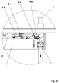
- a first embodiment is in Fig. 1 and 2 shown.
- the detail A shows the locking device in detail. It discloses a fall protection for elevator systems, which is designed with guide posts 5.
- the guide supports 5 have transverse stabilizing struts 14 to support the rollable material 4.
- the mechanical locking is done by locking bolts 6.3 in the active and in the inactive position.
- the fall protection consists of a mounted below the car door sill 1 housing 2, in which a locking device 6 is integrated.
- the loose end of the rollable material 4 is attached to the housing 2 of the elevator car.
- the retractor 3 with the rollable material 4 is movably disposed away from the elevator car at the lower end of the guide posts 5.
- the rollable material 4 is deflected by the retractor 3 by means of a designed as a continuous cross bar deflection device 20 so that the rollable material 4 shows after the deflection in the vertical direction.
- a suitable textile tape is used as a rollable material 4.
- the textile tape is about 950mm wide, so that the door opening width is adequately covered if necessary.
- the textile tape is received at the free, abutting on the car end of a receiving profile 7 and clamped to the housing 2 of the fall protection.
- On the retractor 3 are left and right guide posts 5, which are guided in the housing 2.
- the guide posts 5 can slide between an upper and a lower position and take with it the rollable material 4, which is on the retractor 3 up and unrolled.
- the guide posts 5 are locked by a locking device 6 in the upper and lower positions. In the upper and lower positions are 5 holes in the guide posts introduced such that locking pin 6.3 can engage. By snapping the guide posts 5 are locked.
- the unlocking is done by a trigger plate 11, which acts on the release lever 17 and 18.
- the locking device 6 instead of the release lever 17 and 18 and the release plate 11 consists of at least one release lock 6.1, for example, a triangular lock cylinder and a locking linkage 6.2.
- a solenoid 12 is installed for automatic unlocking. If necessary, can be manually operated with a triangular key serving as a release lock 6.1 lock cylinder on the front of the fall protection.
- a triangular key serving as a release lock 6.1 lock cylinder on the front of the fall protection.
- the position of the car registers the controller 10 via an absolute encoder or via an additional switch in the elevator shaft.
- the speed of the return control is very low and the control is accessible only to a lift attendant.
- the elevator can be moved with activated fall protection only by trained personnel.
- the two 3 and 4 show a lock with a combination of mechanical and electrical means.
- Fig. 3 are the guide posts 5 mechanically released when the car door 24 is open.
- the trip plate is outside the range of the trip levers 17 and 18.
- the solenoid 13 When it is a regular opening of the car door 24 (in normal operation), the solenoid 13 is under tension, the fall protection remains inactive.
- the solenoid When the car door 24 is opened outside the unlocking zone (when the person is being liberated), the solenoid is de-energized and the fall protection active.
- Fig. 4 the car door 24 is closed.
- the trigger plate 11 on the cab door 24 is in contact with the trigger lever 18 and the guide posts 5 are mechanically held by the locking pins 6.3.
- the solenoid 13 is de-energized, no external energy is needed for the retractor. In case of power failure, the fall protection remains inactive, unless the car door 23 is opened.
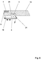
- An in Fig. 5 illustrated embodiment discloses a solution that manages without guide posts.
- the rollable material 4 is guided via a deflection roller 21 to the desired position.
- FIG. 6 illustrated embodiment discloses a fall protection with fold-out and telescopic linkage 19, wherein the retractor 3 is attached to the lower part of the linkage 19.
- the retractor 3 is inserted for further space savings in a recess 25 in the cabin floor 15. Telescoping ensures that the fall protection in the inactive state is short so as not to collide with another fall protection.
- the attached at the bottom retractor 3 supported by its own weight, the extension of the linkage 19th
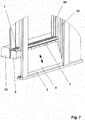
- FIG. 7 Another embodiment is in Fig. 7 shown.
- the fall protection is carried out without guide supports.
- a roller blind serves as a retractor 3, on which as a roll-up material 4, a textile tape is rolled up.
- the textile tape In a 900mm wide door, the textile tape is also about 900mm wide, so that the door opening width is adequately covered if necessary.
- the textile tape is received at the upper end of a receiving profile 7, which is fixed to the housing 2 below the car door sill 1.
- the lock and unlocking is purely mechanical.
- the elevator attendant opens the shaft door 23 completely. Then he unlocks the fall protection and pulls the lower receiving profile 7 with the textile tape to the shaft door 23 and hangs it in this. The roller blind is locked again and the person can be exempted. After the person relief, the fall protection is unlocked with the triangular key, the retractor 3 is released from the shaft door 23 and set back to the inactive state.
- a monitoring switch 8 which registers whether the fall protection is in the upper (inactive) position. As soon as the retractor 3 moves down by a few millimeters, the circuit is interrupted. The controller 10 registers that no more driving may be initiated. A ride with a mounted in the landing door 23 fall protection would result in its destruction.
Landscapes
- Elevator Door Apparatuses (AREA)
- Cage And Drive Apparatuses For Elevators (AREA)
Description
Die Erfindung betrifft einen aufrollbaren Absturzschutz für Aufzugsanlagen, der an Stelle von herkömmlichen Kabinentürschürzen im Bereich der Kabinentürschwelle eingesetzt wird.The invention relates to a roll-up fall protection for elevator systems, which is used instead of conventional cabin door aprons in the area of the car door sill.
Eine Kabinentürschürze in Aufzügen ist gemäß europäischen Aufzugsnormen ein senkrechtes, feststehendes Teil mit 750mm Länge, das bündig mit der Kabinentürschwelle senkrecht nach unten zeigend angebracht ist und verhindern soll, dass Personen bei einer Personenbefreiung in den Aufzugsschacht stürzen können.A cabin door apron in elevators is, according to European elevator standards, a vertical, fixed piece of 750mm length, mounted flush with the car door sill, pointing vertically downwards, to prevent persons from falling into the hoistway when the passenger is cleared.
Bisher ist es üblich, dass geringe Schachtgrubentiefen ab etwa 300mm realisiert werden können. Der Trend geht dabei zu noch geringeren Schachtgrubentiefen. Die nach Aufzugsnormen geforderte Länge der Schürze ist bei der Realisierung der geringen Schachtgrubentiefen hinderlich, da es zwangsläufig zu einer Kollision zwischen Schürze und Schachtgrubenboden kommen würde.So far, it is common that low pit depths can be realized from about 300mm. The trend is towards even lower shaft pit depths. The length of the apron required according to elevator standards hinders the realization of the shallow shaft pit depths, as it would inevitably lead to a collision between the skirt and the shaft pit floor.
Zur Behebung dieses Problems sind verschiedene Lösungen bekannt. Es gibt sowohl teleskopierbare, schwenkbare als auch bei Bedarf manuell zu befestigende Schürzen. Auch einrollbare und einfaltbare Schürzen sind bekannt. Beschrieben werden diese Erfindungen zum Beispiel in
Ein Nachteil der Teleskopschürze für einen Aufzugsfahrkorb nach
Schwenkbare Schürzen, wie in
Manuell zu befestigende Schürzen, wie in
Problematisch ist weiterhin, dass bei einer Schürzenhöhe von lediglich 750mm immer noch ein großes Restrisiko besteht, in den Aufzugsschacht zu fallen, nämlich dann, wenn der Aufzug in einer Höhe stehen bleibt, bei der eingeschlossene Personen den Aufzug gerade noch verlassen können, und gleichzeitig unterhalb der ausgefahrenen Schürze ein Spalt von mehr als 300mm verbleibt. Idealerweise müsste die aktive Schürze etwa so lang sein, wie die Schachttürhöhe. Dies ist mit den bisher benannten Lösungen nicht realisierbar.Another problem is that with a skirt height of only 750 mm there is still a great residual risk of falling into the elevator shaft, namely when the elevator stops at a height at which trapped persons can barely leave the elevator, and at the same time below the extended skirt remains a gap of more than 300mm. Ideally, the active apron would have to be about as long as the shaft door height. This can not be achieved with the previously named solutions.
Einen Lösungsansatz für dieses Problem bieten die Kabinentürschürzen nach
Um Verletzungen zu vermeiden, muss die Vorderseite der Schürze eine möglichst nicht durchbrochene glatte Fläche, bündig mit der Kabinentürschwelle, bilden. Bei
Wird die einrollbare Schürze etwas nach hinten, zur Kabine hin versetzt eingebaut und davor eine feste Schürze angebracht, so muss diese eine Abschrägung wegen der Quetschgefahr in der Entriegelungszone besitzen. Das aufrollbare Material ist dann nicht mehr bündig mit der vorderen Schwellenkante.If the roll-up apron is installed slightly offset to the rear of the cabin and before a fixed apron attached, it must have a chamfer because of the risk of crushing in the unlocking zone. The rollable material is then no longer flush with the front edge of the threshold.
Ein weiterer gravierender Nachteil dieser genannten Lösung ist, dass keine Arretierungseinrichtung zum Straffhalten des aufrollbaren Materials vorgesehen ist. Beim Sturz einer Person gegen die einrollbare Kabinentürschürze baucht das flexible, einrollbare Material in den Aufzugsschacht, wodurch das Risiko für diese Person besteht, durch die dabei entstehenden seitlichen Öffnungen in den Aufzugsschacht zu fallen.Another serious disadvantage of this solution mentioned is that no locking device is provided for keeping the roll-up material in a tight position. When a person falls against the retractable car door apron, the flexible, rollable material bulges in the elevator shaft, whereby the risk for this person to fall through the resulting side openings in the elevator shaft.
Ein weiterer Nachteil der in
Einfaltbare Kabinentürschürzen sind aus
Bei den einfaltbaren Schürzen ist das elastische Material im inaktiven Zustand hintereinander aufgeschichtet. Dieses Aufschichten erfolgt zwangsläufig direkt unterhalb der Kabinentürschwelle. Es ist bei dieser Anordnung nicht auszuschließen, dass sich die einzelnen Schichten in Richtung Schachttür falten. Dies ist insofern ungünstig, weil das elastische Material bei der Aufzugsfahrt an den Schachttüren hängen bleiben und dabei beschädigt werden kann.In the foldable aprons, the elastic material in the inactive state is stacked one behind the other. This layering inevitably takes place directly below the car door sill. With this arrangement, it can not be ruled out that the individual layers fold in the direction of the shaft door. This is unfavorable because the elastic material stuck in the elevator ride on the shaft doors and can be damaged.
Ein weiterer Nachteil aller bekannten Lösungen ist, dass die Schürzen nur aktiviert werden, wenn eine Schachttür mit einem Entriegelungsdreikant geöffnet wird. Bei manuell einzuhängenden Systemen kann die Aktivierung sogar nur manuell durch den Aufzugswärter erfolgen. Bei keinem der bekannten Systeme werden bei einer unbeabsichtigten Bewegung der Kabine aus der Haltestelle die inaktiven Schürzen aktiviert. Eine unbeabsichtigte Bewegung der Kabine aus der Haltestelle ist eine nicht durch die Steuerung innerhalb der Entriegelungszone eingeleitete Bewegung der Kabine mit geöffneter Tür von der Haltestelle weg. Bei inaktiven Schürzen besteht die Gefahr, dass die verbleibende Schürzenlänge zu kurz ist und Personen, die sich in dieser Situation selbst befreien, in den Aufzugsschacht stürzen können.Another disadvantage of all known solutions is that the aprons are activated only when a shaft door is opened with a Entriegelungsdreikant. For manual systems, activation can only be done manually by the lift attendant. In none of the known systems, when the car is unintentionally moved out of the station, the inactive aprons are activated. Inadvertent movement of the car from the stop is a movement of the car with the door open away from the stop, not initiated by the controller within the unlocking zone. With inactive aprons, there is a risk that the remaining apron length is too short and persons who get rid of themselves in this situation can fall into the elevator shaft.
Aufgabe der Erfindung ist es, einen Absturzschutz für Aufzugsanlagen mit geringen Schachtgrubentiefen bereitzustellen, der die genannten Probleme löst und damit ein wesentlich größeres Sicherheitsniveau bietet. Der Absturzschutz soll die aufgeführten Absturz- und Verletzungsgefahren vermeiden und mit deutlich kleinerer Einbauhöhe auskommen. Gleichzeitig soll der Anwendungsbereich des Absturzschutzes möglichst groß sein, sodass er universell für verschiedenste Aufzugstypen verwendbar ist.The object of the invention is to provide a fall protection for elevator systems with low shaft pit depths, which solves the problems mentioned and thus provides a much greater level of security. The fall protection should avoid the listed risk of falling and injury and manage with a much smaller installation height. At the same time, the scope of fall protection should be as large as possible so that it can be used universally for a wide variety of elevator types.
Die Aufgabe wird erfindungsgemäß durch die Merkmale des Anspruches 1 gelöst. Ausgestaltende Merkmale sind in den Unteransprüchen 2 bis 11 beschrieben.The object is achieved by the features of
Der erfindungsgemäße Absturzschutz für Aufzugsanlagen mit einer verfahrbaren Aufzugskabine, bei dem aufrollbares Material von mindestens einer Aufrollvorrichtung auf- und abrollbar ist, ist dadurch gekennzeichnet, dass das lose Ende des aufrollbaren Materials im Bereich der Aufzugskabine befestigt ist und die Aufrollvorrichtung mit dem aufrollbaren Material von der Aufzugskabine weg beweglich angeordnet ist.The fall protection according to the invention for elevator installations with a movable elevator car, in which rollable material can be rolled up and down by at least one retractor, is characterized in that the loose end of the rollable material is fastened in the area of the elevator car and the retractor with the rollable material of the Elevator car is arranged away movable.
Die vorliegende Erfindung löst die genannten Probleme, indem ein sehr kompakter Absturzschutz realisiert wird, der als Ersatz herkömmlicher Kabinentürschürzen im Bereich der Kabinentürschwellen eingebaut wird.The present invention solves the aforementioned problems by realizing a very compact fall protection, which is installed as a replacement of conventional cabin door aprons in the area of the car door sills.
In einer Ausführungsform wird das aufrollbare Material von der Aufrollvorrichtung mittels einer Umlenkvorrichtung so umgelenkt, dass das aufrollbare Material nach der Umlenkung im aktivierten Zustand in vertikale Richtung zeigt. Der Platzbedarf unter der Kabinentürschwelle kann dadurch noch weiter reduziert werden, indem statt einer relativ großen Aufrollvorrichtung lediglich eine relativ kleine Umlenkrolle vorgesehen wird. Die Aufrollvorrichtung kann sich dabei hinter oder oberhalb des tiefsten Ausfahrpunktes befinden, wo sie nicht weiter stört.
Durch diese Anordnung wird erreicht, dass das aufrollbare Material immer bündig zur Kabinentürschwellenkante bzw. zur Kabinendachaußenkante abschließt. Am freien Ende des aufrollbaren Materials kann ein Aufnahmeprofil angebracht sein, welches eine schnelle und einfache Befestigung im Bereich der Kabinentür ermöglicht. Es entsteht ein bündiger Abschluss ohne Vorsprünge oder Schlitze. Ein Verletzungsrisiko kann vermieden werden.In one embodiment, the rollable material is deflected by the retractor by means of a deflection device so that the rollable material after the deflection in the activated state in the vertical direction. The space requirement under the car door sill can thereby be further reduced by only a relatively small pulley is provided instead of a relatively large retractor. The retractor can be located behind or above the deepest exit point where it does not bother.
By this arrangement it is achieved that the rollable material always flush with the car door sill edge or the cabin roof outer edge. At the free end of the rollable material, a receiving profile may be attached, which allows a quick and easy attachment in the cabin door. The result is a flush finish without protrusions or slots. An injury risk can be avoided.
In einer anderen Ausführungsvariante kann der Absturzschutz in offener Bauweise ohne Gehäuse ausgeführt werden. Die Umlenkung des aufrollbaren Materials erfolgt mittels einer horizontal angeordneten Umlenkrolle, die beidseitig gehalten wird.In another embodiment, the fall protection can be performed in an open design without housing. The deflection of the rollable material by means of a horizontally arranged pulley, which is held on both sides.
Weiterhin wird mindestens ein Überwachungsschalter oder ein Überwachungssensor eingesetzt, der die Position des Absturzschutzes (aktiv oder inaktiv) erfasst. Die eingesetzte Steuerung wertet diese Information aus und verhindert, dass der Aufzug bei ausgefahrenem (aktivem) Absturzschutz in den Normalbetrieb übergehen kann. Damit wird unterbunden, dass der Aufzug den ausgefahrenen und arretierten Absturzschutz gegen den Schachtgrubenboden oder gegen die Schachtdecke fährt. Die Steuerung kann die Aufzugssteuerung sein oder eine separate (autarke) Steuereinheit.Furthermore, at least one monitoring switch or a monitoring sensor is used, which detects the position of the fall protection (active or inactive). The controller used evaluates this information and prevents the elevator can go into normal operation with extended (active) fall protection. This prevents that the elevator moves the extended and arrested fall protection against the pit floor or against the shaft ceiling. The control may be the elevator control or a separate (self-sufficient) control unit.
Das aufrollbare Material besteht aus Textilien, Kunststoffen, Bandblech, Leder, Gummi oder Metallgewebe bzw. anderen vollflächigen oder netzartigen Materialien, die sich gut auf- und abrollen lassen und gleichzeitig schwer entflammbar sind. Im Normalbetrieb des Aufzugs ist das aufrollbare Material auf der Aufrollvorrichtung aufgerollt und die Arretierungseinrichtung blockiert das Abrollen des Absturzschutzes in der inaktiven Position. Der Aufzug kann ungehindert den gesamten Aufzugsschacht befahren, eine Kollision zwischen Absturzschutz und Schachtgrubenboden ist ausgeschlossen.The rollable material consists of textiles, plastics, strip, leather, rubber or metal mesh or other full-surface or net-like materials that can be easily rolled up and unrolled and at the same time are flame retardant. During normal operation of the elevator, the rollable material is rolled up on the retractor and the locking device blocks the rolling of the fall protection in the inactive position. The elevator can drive unhindered the entire elevator shaft, a collision between fall protection and pit floor is excluded.
Der Absturzschutz kann sowohl elektrisch als auch rein mechanisch im inaktiven Zustand gehalten (arretiert) werden. Die elektrische Variante sieht vor, dass eine Magnetspule, die während des normalen Betriebes ständig unter Spannung gehalten werden muss, eingesetzt wird. Sobald die Spannung abfällt, ist der Absturzschutz aktiviert. Die mechanische Ausführung beinhaltet im Wesentlichen mechanische Komponenten, wie z.B. ein oder mehrere Entriegelungsschlösser, Verriegelungsgestänge, Rastbolzen und Druckfedern. Die Entriegelung erfolgt durch Verwendung eines Dreikantschlüssels an einem der Entriegelungsschlösser.The fall protection can be held both electrically and purely mechanically in the inactive state (locked). The electrical variant provides that a magnetic coil, which must be kept under tension during normal operation, is used. As soon as the voltage drops, the fall protection is activated. The mechanical design essentially includes mechanical components, such as one or more unlocking locks, locking rods, locking bolts and compression springs. The unlocking is done by using a triangular key on one the unlocking locks.
Der Absturzschutz kann sowohl automatisch (elektrisch) als auch manuell (rein mechanisch) entriegelt (aktiviert) werden. Bei der automatischen Aktivierung wird bei der Entriegelung der Schachttür mittels Entriegelungsdreikant gleichzeitig ein elektrisches Signal an die Steuerung gesendet. Je nach Arretierungsvariante lässt die Steuerung anschließend entweder die Spannung an der Magnetspule abfallen oder es wird kurzzeitig ein Hubmagnet im Absturzschutz angezogen, der Absturzschutz geht anschließend in den aktiven Zustand über. Bei der manuellen Aktivierung erfolgt die Entriegelung mit einem Entriegelungsdreikant an der Vorderseite des Absturzschutzes. Bei einer Personenbefreiung muss der Aufzugswärter die Schachttür nur spaltbreit öffnen, um an ein Entriegelungsschloss zu gelangen.The fall protection can be unlocked (activated) both automatically (electrically) and manually (purely mechanically). In the case of automatic activation, when the shaft door is unlocked, an electrical signal is simultaneously sent to the control by means of the unlocking triangulation. Depending on the locking variant, the controller then either drops the voltage at the solenoid coil or briefly attracts a lifting magnet in the fall protection, and then the fall protection switches to the active state. With manual activation, unlocking takes place with a release triangular on the front of the fall protection. In the event of a person being released, the elevator attendant only has to open the shaft door a few inches to reach a release lock.
In einer bevorzugten Ausführungsform ist die Arretierungseinrichtung als eine Kombination aus mechanischen Mitteln und elektrischen Mitteln ausgebildet, wobei die elektrische Arretierung immer beim regulären Öffnen der Kabinentür (im normalen Betrieb) aktivierbar ist. Die mechanische Verriegelung ist immer bei geschlossener Kabinentür aktiv. Beim nicht regulären Öffnen der Kabinentür (bei Notbefreiung außerhalb der Entriegelungszone) ist weder die elektrische noch die mechanische Verriegelung aktiv. Damit wird bei dieser Lösung der Absturzschutz erst aktiviert, wenn die Kabinentür außerhalb der Entriegelungszone, also unplanmäßig, geöffnet wird. Ziel dieser Variante ist es, Strom zu sparen und Störungen zu vermeiden. Bei einer unbeabsichtigten Bewegung der Kabine aus der Haltestelle wird ein Hubmagnet eingesetzt, der bewirkt, dass die mechanische Arretierung aufgehoben wird.In a preferred embodiment, the locking device is designed as a combination of mechanical means and electrical means, wherein the electrical lock is always activated during regular opening of the car door (in normal operation). The mechanical interlock is always active when the car door is closed. If the car door is not opened normally (in the event of emergency release outside the unlocking zone), neither the electrical nor the mechanical interlock is active. Thus, in this solution, the fall protection is activated only when the car door outside the unlocking, ie unscheduled, is opened. The aim of this variant is to save electricity and avoid interference. In an unintentional movement of the car from the stop a solenoid is used, which causes the mechanical lock is released.
Bei einer unbeabsichtigten Bewegung der Kabine aus der Haltestelle bewegt sich die Kabine bei geöffneter Schachttür aus der Haltestelle. Es kann zu einer größeren Lücke zwischen Etagenboden und Kabinentürschwelle kommen, durch die Personen in den Aufzugsschacht abstürzen können. Um diese Öffnung zu schließen, wird der Absturzschutz bei Erkennen der unbeabsichtigten Bewegung aktiviert. Ausgelöst wird dies durch die Steuerung, die in der Lage ist, eine unbeabsichtigte Bewegung der Kabine aus der Haltestelle zu erkennen und darauf zu reagieren.In the event of an unintentional movement of the car from the stop, the car moves out of the stop when the landing door is open. There may be a larger gap between the floor of the floor and the car door sill, which may cause people to fall into the elevator shaft. To this opening too close, the fall protection is activated upon detection of unintentional movement. This is triggered by the control, which is able to detect an unintentional movement of the car from the stop and respond to it.
Bisherige Lösungen bestanden darin, dass ständig Strom führende Haftmagnete den Absturzschutz gehalten haben. Bei Stromausfall fiel der Absturzschutz nach unten und ein Service-Monteur musste vor Ort den Absturzschutz in die inaktive Stellung zurücksetzen.Previous solutions consisted in the fact that constantly holding current magnets held the fall protection. In case of power failure, the fall protection fell down and a service technician had to reset the fall protection to the inactive position on site.
Optional wird der Absturzschutz mit Führungsstützen ausgestattet, die in Kombination mit der Arretierungseinrichtung das aufrollbare Material sowohl im aktiven als auch im inaktiven Zustand straff halten und ein Ausweichen des aufrollbaren Materials in den Aufzugsschacht verhindern. Die Führungsstützen sind dabei so weit ausfahrbar, wie es die Arretierungseinrichtung zulässt.Optionally, the fall protection is provided with guide posts which, in combination with the locking device, keep the rollable material taut in both the active and inactive states and prevent the roll-up material from dodging into the elevator shaft. The guide supports are extendable as far as the locking device allows.
Die Führungsstützen bewirken in Kombination mit der Aufrollvorrichtung durch ihr Eigengewicht, also ohne weitere Zuführung von Energie das Absenken des Absturzschutzes in den aktiven Zustand nach dem Entriegeln. Sie arbeiten dabei gegen die Federkraft der Aufrollvorrichtung. Der Absturzschutz kann zur Unterstützung des Absenkvorganges mit Druckfedern ausgestattet werden. Dies kann dann von Vorteil sein, wenn die Kraft der Aufrollvorrichtung größer als das Eigengewicht der Führungsstützen und der Aufrollvorrichtung ist oder wenn der Absturzschutz auf dem Kabinendach eingesetzt wird und die Führungsstützen nach oben fahren müssen.The guide supports cause in combination with the retractor by its own weight, so without further supply of energy lowering the fall protection in the active state after unlocking. They work against the spring force of the retractor. The fall protection can be equipped to support the lowering process with compression springs. This can be advantageous if the force of the retractor is greater than the weight of the guide posts and the retractor or if the fall protection is used on the cab roof and the guide posts must go up.
Optional wird durch die Steuerung überwacht und sichergestellt, dass der Absturzschutz ausschließlich in einer definierten Position in der untersten Haltestelle in ihre inaktive Position zurückgesetzt werden kann. Es wird damit verhindert, dass der Aufzugswärter beim Aufrollen des Absturzschutzes von einem gefährlichen Höhenniveau in den Aufzugsschacht fallen kann. In der untersten Haltestelle ist ein Absturz in einen Aufzugsschacht mit verkürzter Schachtgrube unkritisch. Ein Zurücksetzen des Absturzschutzes ist in diesem Bereich daher ebenfalls unkritisch. Die Kabine wird mit Rückholsteuerung und aktivem Absturzschutz in diesen Bereich gefahren.Optionally, the controller monitors and ensures that the fall protection can only be reset to its inactive position in a defined position in the lowest station. It is thus prevented that the elevator attendant when rolling the fall protection of a dangerous height level in the elevator shaft can fall. In the lowest station is a crash into a lift shaft with shortened pit pit uncritical. Resetting the fall protection is therefore also not critical in this area. The cabin is driven into this area with return control and active fall protection.
Es kann Kabinen geben, in denen die ausfahrbaren Führungsstützen unerwünscht sind (z.B. bei Glasaufzügen) oder die Führungsstützen können aus Platzgründen nicht untergebracht werden. Bei diesen Anwendungsfällen kann der Absturzschutz ohne die Führungsstützen so ausgeführt werden, dass die Aufrollvorrichtung im Schachttürrahmen oder der Schachttürschwelle eingehängt wird. Um das aufrollbare Material straff zu halten, wird die Aufrollvorrichtung im aktiven als auch im inaktiven Zustand des Absturzschutzes arretiert.There may be booths in which the extendable guide posts are undesirable (e.g., in glass elevators) or the guide posts may not be accommodated for space. In these applications, the fall protection without the guide posts can be carried out so that the retractor is mounted in the hoistway door or the shaft door sill. In order to keep the rollable material taut, the retractor is locked in the active and inactive state of fall protection.
Alternativ zu den Führungsstützen wird das aufrollbare Material durch ein beim Aktivieren sich selbst ausklappendes und verriegelndes Gestänge straff gehalten.As an alternative to the guide supports, the rollable material is held taut by a self-folding and locking rod when activated.
Mit dem beschriebenen Absturzschutz wird erreicht, dass dessen Länge im ausgefahrenen (aktiven) Zustand wesentlich länger sein kann, als dies bei allen bisher bekannten Kabinentürschürzen der Fall ist, wodurch ein Maximum an Sicherheit erreicht wird. Dies liegt daran, dass die ausfahrbare Länge des Absturzschutzes nicht von der Schachtgrubentiefe abhängig ist, sondern bei der Variante mit Führungsstützen von der Kabinentürhöhe, da die ausfahrbaren Führungsstützen in die Kabinentüreinzüge hineinfahren. Eine Kabinentür ist mindestens 2,0m hoch, die Führungsstützen können also ebenfalls etwa 2,0m lang sein.With the described fall protection ensures that its length in the extended (active) state can be much longer than is the case with all previously known cabin door aprons, whereby a maximum of security is achieved. This is due to the fact that the extendable length of the fall protection is not dependent on the shaft pit depth, but in the variant with guide supports of the cabin door height, as the extendable guide supports drive into the car door drawers. A cabin door is at least 2.0m high, so the guide posts can also be about 2.0m long.
Bei der Variante ohne Führungsstützen im Aufzugsschacht ist die Länge des aktiven Absturzschutzes von der Länge des Gestänges abhängig.In the variant without guide posts in the elevator shaft, the length of the active fall protection depends on the length of the linkage.
Bei Anordnung des Absturzschutzes ausschließlich unterhalb der Kabinentürschwelle wird kein Platz in der Projektion der Kabinenfläche belegt, weder im aufgerollten (inaktiven) noch im abgerollten (aktiven) Zustand. Die Kabinentüren können bei dieser Variante unabhängig vom Absturzschutz angeordnet werden, ohne dass es Berührungspunkte zwischen mehreren Absturzschutzvorrichtungen an der Kabine gibt.When the fall protection is installed only below the car door sill, there is no space in the projection of the Cabin area occupied, neither in rolled up (inactive) nor in unrolled (active) state. The cabin doors can be arranged independently of the fall protection in this variant, without there being points of contact between several fall protection devices on the cabin.
Prinzipiell gilt, dass ein langes aufrollbares Material auf einer verhältnismäßig kleinen Aufrollvorrichtung aufgerollt werden kann, wodurch eine sehr geringe Bauhöhe erreicht wird. Der Absturzschutz wird mit einer oder mehreren Aufrollvorrichtungen ausgestattet. Bei der Verwendung von einer Aufrollvorrichtung ist der Gesamtdurchmesser inklusive aufgerolltem Material größer, als wenn mehrere kleine Aufrollvorrichtungen verwendet werden. Zwei nebeneinander angeordnete Aufrollvorrichtungen bedürfen eines größeren Fertigungsaufwandes, haben aber eine kleinere Einbauhöhe, als eine einzelne Aufrollvorrichtung. Je nach Schachtgrubentiefe ist die eine oder die andere Variante vorteilhafter.In principle, a long roll-up material can be rolled up on a relatively small retractor, whereby a very low height is achieved. The fall protection is equipped with one or more retractors. When using a retractor, the overall diameter, including rolled-up material, is greater than when multiple small retractors are used. Two juxtaposed retractors require greater manufacturing effort, but have a smaller installation height, as a single retractor. Depending on the shaft pit depth, one or the other variant is more advantageous.
Durch das Umlenken des aufrollbaren Materials kann die Aufrollvorrichtung in einem frei wählbaren Bereich entweder unterhalb der Kabinentürschwelle, des Einzuges oder des Kabinenbodens angeordnet werden. Sie kann sogar im Kabinenboden eingelassen sein. Dadurch wird eine noch geringere Einbauhöhe erreicht, als bei allen bisher bekannten Lösungen. Es können Schachtgruben mit einer Tiefe kleiner als 150mm bedient werden.By deflecting the rollable material, the retractor can be arranged in a freely selectable area either below the car door sill, the feeder or the cabin floor. It can even be embedded in the cabin floor. As a result, an even lower installation height is achieved than in all previously known solutions. Pit pits with a depth of less than 150mm can be operated.
Gemäß Aufzugsnormen muss die Länge der inaktiven Schürze wenigstens der Entriegelungszone entsprechen, also dem Bereich, in dem die Aufzugstüren im normalen Betriebszustand geöffnet werden. Es kann sonst zum Abscheren der Zehen im Einstiegsbereich der Kabinentür kommen. Bei kleinen Schürzen kann es also auch nur eine kleine Entriegelungszone geben. Da dies unerwünscht ist, wird der Absturzschutz je nach Schachtgrubentiefe im inaktiven Zustand nur so weit aufgerollt, wie es bei der vorhandenen Schachtgrube möglich ist, ohne dass es bei der normalen Aufzugsfahrt zu Berührung mit dem Schachtgrubenboden kommt. Es muss nicht, wie sonst üblich, für jeden Aufzug je nach Schachtgrubentiefe eine eigene Schürzenlänge hergestellt werden. Es wird immer der gleiche Absturzschutz verwendet. Eine Serienfertigung wird ermöglicht. Ausschließlich die Arretierungsposition im inaktiven Zustand muss angepasst werden, d.h. das Loch in den Führungsstützen, in welches der Rastbolzen einrastet, muss an die Gegebenheiten angepasst werden.According to elevator standards, the length of the inactive apron must at least correspond to the unlocking zone, ie the area in which the elevator doors are opened in the normal operating state. Otherwise it may come to shearing the toes in the entry area of the cabin door. With small aprons, there can only be a small unlocking zone. Since this is undesirable, the fall protection is depending on the shaft pit depth in the inactive state only rolled up as far as it is possible for the existing pit, without it in the normal elevator ride to contact the pit floor comes. It does not, as usual, for each elevator, depending on the shaft pit depth, a separate apron length be made. It is always the same fall protection used. A series production is possible. Only the locking position in the inactive state must be adjusted, ie the hole in the guide supports, in which the locking bolt engages, must be adapted to the circumstances.
Eine wesentliche Verbesserung für die Sicherheit wird erreicht, indem der Absturzschutz bei unbeabsichtigter Bewegung der Kabine aus der Haltestelle aktiviert wird. Erst durch diese Option ist es möglich, kleine Schachtgruben zu realisieren und das erforderliche Sicherheitsniveau einzuhalten. Hintergrund ist der, dass die unbeabsichtigte Bewegung erst nach Verlassen der Entriegelungszone (nach etwa 200mm) erkannt wird und die Kabine anschließend abgebremst wird. Alle dabei beteiligten Komponenten haben Verzögerungszeiten, wodurch die Kabine erst sehr weit von der Haltestelle entfernt zum Stehen kommt. Die Lücke zwischen Etagenboden und inaktivem Absturzschutz wäre so groß, dass Personen in den Aufzugsschacht fallen können. Durch das Aktivieren des Absturzschutzes wird die Lücke sicher geschlossen.A significant improvement in safety is achieved by activating the fall protection in the event of unintentional movement of the car from the landing. Only with this option is it possible to realize small pits and to maintain the required safety level. The background to this is that the unintentional movement is detected only after leaving the unlocking zone (after about 200 mm) and the car is then braked. All the components involved have delay times, causing the car to come to a stop very far from the stop. The gap between floor level and inactive fall protection would be so great that people can fall into the elevator shaft. Activating the fall protection closes the gap safely.
Eine wesentliche Erhöhung der Sicherheit wird durch das automatische Aktivieren beim Öffnen der Schachttüren mit Entriegelungsdreikant erreicht. Die Sicherheit wird sowohl im Kabinentürschwellenbereich als auch auf dem Kabinendach sofort und automatisch hergestellt. Das Aktivieren kann damit auch nicht vom Aufzugswärter vergessen werden.A significant increase in safety is achieved by the automatic activation when opening the shaft doors with unlocking triangular. Safety is instantly and automatically produced both in the cabin door sill area and on the cabin roof. Activation can therefore not be forgotten by the elevator attendant.
Trotz der sehr kompakten Bauweise wird erreicht, dass in jedem Betriebszustand ein Absturzschutz mit einer glatten Flä-, che bündig mit der Kabinentürschwelle, bei Einbau in diesem Bereich, realisiert wird. Die unter der Kabinentür entstehende Öffnung wird stets sicher abgedeckt. Durch die Arretierungseinheit ist das aufrollbare Material stets straff und ein Bauchen in den Aufzugsschacht unmöglich.Despite the very compact construction, it is achieved that in every operating condition a fall protection with a smooth surface is achieved, flush with the car door sill, when installed in this area. The opening under the car door is always safely covered. By locking unit, the rollable material is always taut and a belly in the elevator shaft impossible.
Durch das Aufrollen des aufrollbaren Materials wird dieses von der Kabinentürschwelle weggeführt. Es verbleibt nicht im Bereich der Schachttüren, wie bei den einfaltbaren Schürzen aus
Nachfolgend wird die Erfindung an mehreren Ausführungsbeispielen und den nachfolgend aufgeführten Abbildungen näher erläutert. Es zeigen:
- Fig. 1
- Absturzschutz im aktiven Zustand mit Führungsstützen und mit einer Kombination aus mechanischen und elektrischen Mitteln zur Arretierung; die Entriegelung erfolgt mittels Hubmagnet oder Auslöseplatte;
- Fig. 2
- Absturzschutz im aktiven Zustand mit Führungsstützen und mit einer Kombination aus mechanischen und elektrischen Mitteln zur Arretierung; die Entriegelung erfolgt mittels Hubmagnet oder Entriegelungsschloss;
- Fig. 3
- Absturzschutz mit einer Kombination aus mechanischen und elektrischen Mitteln zur Arretierung-Kabinentür ist auf;
- Fig. 4
- Absturzschutz mit einer Kombination aus mechanischen und elektrischen Mitteln zur Arretierung-Kabinentür ist zu;
- Fig. 5
- im Kabinenboden angeordneter Absturzschutz im aktiven Zustand mit Gestänge;
- Fig. 6
- Absturzschutz im inaktiven Zustand mit einem teleskopierbaren Gestänge;
- Fig. 7
- Absturzschutz ohne Führungsstützen im aktiven Zustand, bei dem die Aufrollvorrichtung in eine Schachttür eingehängt ist.
- Fig. 1
- Fall protection in the active state with guide posts and with a combination of mechanical and electrical means for locking; the release takes place by means of solenoid or trip plate;
- Fig. 2
- Fall protection in the active state with guide posts and with a combination of mechanical and electrical means for locking; the release takes place by means of lifting magnet or unlocking lock;
- Fig. 3
- Crash protection with a combination of mechanical and electrical means to lock car door is on;
- Fig. 4
- Fall protection with a combination of mechanical and electrical means to lock car door is too;
- Fig. 5
- in the cabin floor arranged fall protection in the active state with linkage;
- Fig. 6
- Fall protection in inactive condition with a telescopic boom;
- Fig. 7
- Fall protection without guide posts in the active state, in which the retractor is mounted in a shaft door.
Ein erstes Ausführungsbeispiel ist in
Der Absturzschutz besteht aus einem unterhalb der Kabinentürschwelle 1 angebrachten Gehäuse 2, in dem eine Arretierungseinrichtung 6 integriert ist. Das lose Ende des aufrollbaren Materials 4 ist am Gehäuse 2 der Aufzugskabine befestigt. Die Aufrollvorrichtung 3 mit dem aufrollbaren Material 4 ist von der Aufzugskabine weg beweglich am unteren Ende der Führungsstützen 5 angeordnet. Das aufrollbare Material 4 wird von der Aufrollvorrichtung 3 mittels einer als durchgehende Querleiste ausgebildeten Umlenkvorrichtung 20 so umgelenkt, dass das aufrollbare Material 4 nach der Umlenkung in vertikale Richtung zeigt.The fall protection consists of a mounted below the
Als aufrollbares Material 4 wird ein geeignetes Textilband verwendet. Bei einer 900mm breiten Tür ist das Textilband etwa 950mm breit, damit die Türöffnungsbreite im Bedarfsfall ausreichend überdeckt wird. Das Textilband wird an dessen freien, an der Kabine anschlagendem Ende, von einem Aufnahmeprofil 7 aufgenommen und am Gehäuse 2 des Absturzschutzes festgeklemmt. An der Aufrollvorrichtung 3 befinden sich links und rechts Führungsstützen 5, die im Gehäuse 2 geführt werden. Die Führungsstützen 5 können zwischen einer oberen und einer unteren Position gleiten und nehmen dabei das aufrollbare Material 4 mit, wobei dieses auf der Aufrollvorrichtung 3 auf- und abgerollt wird.As a
Die Führungsstützen 5 werden durch eine Arretierungseinrichtung 6 in der oberen und unteren Position verriegelt. In der oberen und unteren Position sind in den Führungsstützen 5 Löcher derart eingebracht, dass Rastbolzen 6.3 einrasten können. Durch das Einrasten werden die Führungsstützen 5 verriegelt. In
Durch die Schwerkraft gleiten die Führungsstützen 5 mit der Aufrollvorrichtung 3 in die untere Position und nehmen dabei das Textilband mit. Dieses wird dadurch so aufgespannt, dass der Absturzbereich vollflächig abgedeckt ist. In der unteren Position rasten die Rastbolzen 6.3 in die dafür vorgesehenen Löcher ein und die Führungsstützen 5 sind erneut verriegelt.By gravity, the guide supports 5 slide with the
Damit ein Aufzugswärter bei einer Personenbefreiung den Absturzschutz nicht manuell aktivieren muss, wird in den Schachttüren ein zusätzlicher Kontakt eingebaut, der registriert, wenn eine Schachttür mit Entriegelungsdreikant geöffnet wird. Dieser Kontakt gibt ein Signal an die Steuerung 10, welche anschließend den im Absturzschutz zusätzlich integrierten Hubmagnet 12 anziehen lässt. Dieser zieht am Verriegelungsgestänge 6.2 und die Führungsstützen 5 können nach unten gleiten, wo sie erneut verriegelt werden.
Am Absturzschutz befindet sich ein Überwachungsschalter 8 oder -sensor, der kontrolliert, ob sich der Absturzschutz in der oberen (inaktiven) Position befindet. Sobald sich die Aufrollvorrichtung 3 wenige Millimeter nach unten bewegt, wird der Stromkreis unterbrochen. Die Steuerung 10 registriert, dass Normalfahrt nicht mehr eingeleitet werden darf. Der Aufzug kann nun nur noch bis zu einer definierten Position in der untersten Haltestelle mit Rückholsteuerung verfahren werden. Die Position der Kabine registriert die Steuerung 10 über einen Absolutwertgeber oder über einen zusätzlichen Schalter im Aufzugsschacht. Die Geschwindigkeit der Rückholsteuerung ist sehr gering und die Steuerung ist nur einem Aufzugswärter zugänglich. Damit kann der Aufzug bei aktiviertem Absturzschutz nur von eingewiesenem Personal verfahren werden. Durch die genannten Maßnahmen wird sichergestellt, dass der ausgefahrene und arretierte Absturzschutz nicht den Schachtgrubenboden berührt, wodurch er beschädigt werden würde.So that an elevator attendant does not have to activate the fall protection manually in the event of a person being released, an additional contact is installed in the shaft doors, which registers when a shaft door is opened with an unlocking triangular. This contact gives a signal to the
The fall protection has a
In der unteren (aktiven) Position rasten nicht nur die Rastbolzen 6.3 in die Führungsstützen 5 ein, sondern auch mindestens ein Verriegelungsmagnet 9. Dieser Verriegelungsmagnet 9 verhindert, dass der Absturzschutz in einer der oberen Haltestellen in den inaktiven Zustand zurückversetzt werden kann. Lediglich in der definierten Position in der unteren Haltestelle gibt die Steuerung den Verriegelungsmagnet 9 frei. Mit einem Entriegelungsdreikant wird dann ein Dreikant-Schließzylinder betätigt, die Rastbolzen 6.3 geben die Führungsstützen 5 frei und der Absturzschutz kann in die inaktive Position zurückgesetzt werden. Das Textilband wird dabei durch die Aufrollvorrichtung 3 selbsttätig aufgerollt.In the lower (active) position engage not only the locking pin 6.3 in the guide supports 5, but also at least one
Die beiden
In
Ein in
Das in
Ein weiteres Ausführungsbeispiel ist in
Bei einer Personenbefreiung öffnet der Aufzugswärter die Schachttür 23 komplett. Anschließend entriegelt er den Absturzschutz und zieht das untere Aufnahmeprofil 7 mit dem Textilband zur Schachttür 23 und hängt es in diese ein. Das Rollo wird wieder verriegelt und die Personenbefreiung kann erfolgen. Nach der Personenbefreiung wird der Absturzschutz mit dem Dreikantschlüssel entriegelt, die Aufrollvorrichtung 3 aus der Schachttür 23 ausgehangen und in den inaktiven Zustand zurückversetzt.In a passenger exemption the elevator attendant opens the
An dem Absturzschutz befindet sich ein Überwachungsschalter 8, der registriert, ob sich der Absturzschutz in der oberen (inaktiven) Position befindet. Sobald sich die Aufrollvorrichtung 3 um wenige Millimeter nach unten bewegt, wird der Stromkreis unterbrochen. Die Steuerung 10 registriert, dass keine Fahrt mehr eingeleitet werden darf. Eine Fahrt bei einem in der Schachttür 23 eingehängten Absturzschutz hätte dessen Zerstörung zur Folge.At the fall protection is a
- 11
- KabinentürschwelleCar door sill
- 22
- Gehäusecasing
- 33
- Aufrollvorrichtungretractor
- 44
- aufrollbares MaterialRoll-up material
- 55
- Führungsstützenguide posts
- 66
- Arretierungseinrichtunglocking device
- 6.16.1
- EntriegelungsschlossRelease lock
- 6.26.2
- Verriegelungsgestängelocking linkage
- 6.36.3
- RastbolzenIndexing plungers
- 6.46.4
- Druckfedercompression spring
- 77
- AufnahmeprofilUp profile
- 88th
- Überwachungsschaltermonitoring switch
- 99
- Verriegelungsmagnetlocking magnet
- 1010
- Steuerungcontrol
- 1111
- Auslöseplatterelease plate
- 1212
- Hubmagnetsolenoid
- 1313
- Magnetspulesolenoid
- 1414
- Stabilisierungsstrebenstabilizing struts
- 1515
- Kabinenbodencabin floor
- 1616
- Schachtdeckeshaft ceiling
- 1717
-
Auslösehebel 1
Release lever 1 - 1818
-
Auslösehebel 2
Release lever 2 - 1919
- Gestängelinkage
- 2020
- Umlenkvorrichtungdeflecting
- 2121
- Umlenkrolleidler pulley
- 2222
- Kabinendachcanopy
- 2323
- Schachttürshaft door
- 2424
- Kabinentürcabin door
- 2525
- Aussparungrecess
Claims (11)
- Fall protector for lift systems having a movable lift car, in which rollable material (4) can be rolled up on and unrolled from at least one roll-on device (3), characterized in that the loose end of the rollable material (4) is fastened in the region of the car door sill of the lift car and the roll-on device (3) with the rollable material (4) is arranged so as to be movable downwardly away from the lift car.
- Fall protector according to Claim 1, characterized in that the rollable material (4) is deflected from the roll-on device (3) by means of a deflection device (20) such that, after deflection, the rollable material (4) points in the vertical direction in the activated state.
- Fall protector according to Claim 1 or 2, characterized in that a receiving profile (7) is situated at the loose end of the rollable material (4).
- Fall protector according to one of Claims 1 to 3, characterized in that at least one arresting device (6) arrests the rollable material (4) in the rolled-up (inactive) and/or unrolled (active) state.
- Fall protector according to Claim 4, characterized in that the arresting device (6) is formed as a combination of mechanical means and electrical means, wherein electrical arresting can always be activated during regular opening of the car door and mechanical arresting can always be activated with the car door closed.
- Fall protector according to one of Claims 1 to 5, characterized in that the fall protector is equipped with a monitoring switch (8) or sensor and a controller (10) which monitor and ensure that the lift can travel only at nominal speed if the fall protector is in the rolled-up (inactive) state.
- Fall protector according to one of Claims 1 to 6, characterized in that the rollable material (4) is designed to be full-surface, lamellar or net-like and consists of textiles, plastics, leather, rubber, woven metal fabric or strip metal sheet.
- Fall protector according to one of Claims 1 to 7, characterized in that the rollable material (4) can be guided, tensioned and held in its position by extendable guide supports (5).
- Fall protector according to one of Claims 1 to 7, characterized in that the rollable material (4) can be tensioned and held in its position by a fold-out rod system (19).
- Fall protector according to one of Claims 1 to 9, characterized in that the fall protector is equipped with a switch or sensor and a controller (10) which cause the fall protector to be activated if, in the event of an unintended car movement, the lift car moves away from the landing.
- Fall protector according to one of Claims 1 to 10, characterized in that the fall protector is equipped with a switch or sensor and a controller (10) which cause the arresting device (6) to release the rollable material (4) for roll-up purposes only when the lift car is in a defined region in the lowermost landing.
Priority Applications (1)
| Application Number | Priority Date | Filing Date | Title |
|---|---|---|---|
| PL12401205T PL2581334T3 (en) | 2011-10-14 | 2012-10-12 | Fall Protection for Elevators |
Applications Claiming Priority (1)
| Application Number | Priority Date | Filing Date | Title |
|---|---|---|---|
| DE201120051638 DE202011051638U1 (en) | 2011-10-14 | 2011-10-14 | Fall protection for elevator systems |
Publications (3)
| Publication Number | Publication Date |
|---|---|
| EP2581334A1 EP2581334A1 (en) | 2013-04-17 |
| EP2581334A8 EP2581334A8 (en) | 2013-05-29 |
| EP2581334B1 true EP2581334B1 (en) | 2016-08-31 |
Family
ID=45347262
Family Applications (1)
| Application Number | Title | Priority Date | Filing Date |
|---|---|---|---|
| EP12401205.5A Active EP2581334B1 (en) | 2011-10-14 | 2012-10-12 | Fall Protection for Elevators |
Country Status (5)
| Country | Link |
|---|---|
| EP (1) | EP2581334B1 (en) |
| DE (1) | DE202011051638U1 (en) |
| ES (1) | ES2605558T3 (en) |
| HU (1) | HUE032077T2 (en) |
| PL (1) | PL2581334T3 (en) |
Cited By (2)
| Publication number | Priority date | Publication date | Assignee | Title |
|---|---|---|---|---|
| US11235952B2 (en) | 2018-08-10 | 2022-02-01 | Otis Elevator Company | Elevator car apron |
| US11267679B2 (en) | 2018-08-10 | 2022-03-08 | Otis Elevator Company | Elevator car apron |
Families Citing this family (14)
| Publication number | Priority date | Publication date | Assignee | Title |
|---|---|---|---|---|
| ES2597969T3 (en) | 2011-04-05 | 2017-01-24 | Otis Elevator Company | Toe protection set for a lifting system |
| DE102016121742A1 (en) * | 2016-11-14 | 2018-05-17 | Thyssenkrupp Ag | Car for an elevator system |
| CN106629296A (en) * | 2017-02-24 | 2017-05-10 | 江南嘉捷电梯股份有限公司 | Telescopic rod type anti-falling emergency protection device for elevator shaft |
| GR1009417B (en) * | 2017-09-12 | 2018-12-14 | Κλεμαν Ελλας-Kleeman Hellas Α.Β.Ε.Ε. Για Μηχανολογικες Κατασκευες Α.Ε. | Foldable elevator's cabin skirt made of flexible material and provided with support levers and air springs |
| EP3530605B1 (en) * | 2018-02-23 | 2021-09-15 | Otis Elevator Company | Elevator car toe guard system |
| CN108750846B (en) * | 2018-06-29 | 2024-07-16 | 上海德圣米高电梯有限公司 | Elevator car leveling position supporting device |
| EP3599210B1 (en) * | 2018-07-26 | 2022-05-04 | Otis Elevator Company | Elevator car apron |
| EP3599211B1 (en) * | 2018-07-26 | 2020-09-09 | Otis Elevator Company | Elevator car apron |
| EP3608281B1 (en) * | 2018-08-06 | 2021-11-10 | Otis Elevator Company | Elevator car apron |
| EP3656720B1 (en) * | 2018-11-22 | 2021-09-01 | Otis Elevator Company | Elevator car apron |
| CN114531871B (en) * | 2019-09-30 | 2023-11-17 | 因温特奥股份公司 | Elevator installation |
| CN113353752A (en) * | 2021-05-19 | 2021-09-07 | 重庆市华创电梯部件有限公司 | Device for preventing accidental movement of elevator car |
| CN114394511B (en) * | 2022-01-19 | 2023-08-15 | 日立楼宇技术(广州)有限公司 | Elevator maintenance door opening method, device, equipment and storage medium |
| CN118026032B (en) * | 2024-04-12 | 2024-06-21 | 龙岩市宝泰饲料有限公司 | Fodder raw materials hoisting device |
Family Cites Families (12)
| Publication number | Priority date | Publication date | Assignee | Title |
|---|---|---|---|---|
| DE1052459B (en) | 1957-05-15 | 1959-03-12 | Fritz Schwarzer | Multi-stage push-pull direct current amplifier |
| EP1118576B1 (en) | 2000-01-21 | 2005-04-06 | ThyssenKrupp Aufzugswerke GmbH | Toe guard for elevator car |
| DE10052459A1 (en) | 2000-10-23 | 2002-05-02 | Mueller Wolfgang T | Devices for formation of protection space for lifts without machine space with reduced shaft has retractable apron designed as stable frame open upwards which is slid in guides mounted on cabin or in shaft head |
| FI20002743A (en) | 2000-12-14 | 2002-06-15 | Kone Corp | Foot protection |
| DE20313911U1 (en) | 2003-09-08 | 2003-11-13 | Oelsmeier, Ingo, Dipl.-Ing., 59558 Lippstadt | Apron for lift for protection of persons in event of emergency freeing is extendable hence variable in length, and bars of apron are connected via levers which ensure that spacing of bars in relation to each other always remains same |
| DK1524234T3 (en) | 2003-10-13 | 2007-01-22 | Lm Liftmaterial Gmbh | Elevator System |
| FR2891820B1 (en) * | 2005-10-07 | 2008-12-05 | Thyssenkrupp Elevator Mfg F | ELEVATOR SYSTEM COMPRISING A SAFETY DEVICE |
| DE102006045499A1 (en) | 2006-09-27 | 2008-04-03 | TÜV Rheinland Industrie Service GmbH | Elevator cabin with safety function has protective device permanently arranged on at least one deployment element that moves in shaft of elevator system to protect at least one person that may be present in shaft |
| DE102008038409B4 (en) | 2007-08-28 | 2016-12-22 | Thoma Aufzüge Gmbh | Device for securing manhole access of elevator installations |
| DE102008038408A1 (en) | 2007-08-28 | 2009-03-05 | Elt Electronic Lift Thoma Gmbh | Cabin door skirt for e.g. passenger lift, has permanent magnets holding skirt in folded condition, where skirt is made of material e.g. textile or fabric, and manually or automatically folded in or out multiple time |
| DE102007046577A1 (en) | 2007-09-27 | 2009-04-02 | W+W Aufzugkomponenten Gmbh U. Co. Kg | Telescopic apron for a lift car |
| EP2138443A1 (en) | 2008-06-04 | 2009-12-30 | Mac Puar, S.A. | Folding skirt for a lift cabin |
-
2011
- 2011-10-14 DE DE201120051638 patent/DE202011051638U1/en not_active Expired - Lifetime
-
2012
- 2012-10-12 EP EP12401205.5A patent/EP2581334B1/en active Active
- 2012-10-12 PL PL12401205T patent/PL2581334T3/en unknown
- 2012-10-12 ES ES12401205.5T patent/ES2605558T3/en active Active
- 2012-10-12 HU HUE12401205A patent/HUE032077T2/en unknown
Cited By (2)
| Publication number | Priority date | Publication date | Assignee | Title |
|---|---|---|---|---|
| US11235952B2 (en) | 2018-08-10 | 2022-02-01 | Otis Elevator Company | Elevator car apron |
| US11267679B2 (en) | 2018-08-10 | 2022-03-08 | Otis Elevator Company | Elevator car apron |
Also Published As
| Publication number | Publication date |
|---|---|
| PL2581334T3 (en) | 2017-07-31 |
| DE202011051638U1 (en) | 2011-11-16 |
| ES2605558T3 (en) | 2017-03-15 |
| EP2581334A8 (en) | 2013-05-29 |
| EP2581334A1 (en) | 2013-04-17 |
| HUE032077T2 (en) | 2017-08-28 |
Similar Documents
| Publication | Publication Date | Title |
|---|---|---|
| EP2581334B1 (en) | Fall Protection for Elevators | |
| EP1772414B1 (en) | Foldable self-locking toe guard for elevator car | |
| DE69926244T2 (en) | Shaft safety system for lift | |
| EP3007953B1 (en) | Protective wall for protecting persons from travelling rail vehicles | |
| DE602004004600T2 (en) | Device for manual unlocking | |
| DE69113816T2 (en) | LIFT. | |
| EP0725033A1 (en) | Temporary securing of a working space | |
| WO2012126619A1 (en) | Elevator having a minimal shaft top height and a permanent protective space | |
| EP1930285B1 (en) | Lift facility with a safety device fitted on the lift doors | |
| EP3696116A1 (en) | High-bay storage and method for operating same | |
| DE102008038408A1 (en) | Cabin door skirt for e.g. passenger lift, has permanent magnets holding skirt in folded condition, where skirt is made of material e.g. textile or fabric, and manually or automatically folded in or out multiple time | |
| DE102019211973A1 (en) | Safety device for an elevator car that moves in a horizontal direction | |
| DE102008038409B4 (en) | Device for securing manhole access of elevator installations | |
| DE10052459A1 (en) | Devices for formation of protection space for lifts without machine space with reduced shaft has retractable apron designed as stable frame open upwards which is slid in guides mounted on cabin or in shaft head | |
| DE10065101A1 (en) | Elevator has movable protective device beneath elevator cabin with at least one rotation axis or shaft for pivoting the device and locking arrangement for fixing deployed protective device | |
| DE60308684T2 (en) | elevator system | |
| DE102017004719A1 (en) | Device for a secured area in a hoistway | |
| DE69304255T2 (en) | Smoke apron | |
| CH714341B1 (en) | Elevator installation with a car comprising a collecting device. | |
| EP2325128B1 (en) | Lift assembly for people and/or loads with at least one lift cabin | |
| DE20202775U1 (en) | Elevator with a temporary shelter | |
| EP2172411B1 (en) | Lift system with position-dependant door lock | |
| DE2460337C3 (en) | Elevator with a hydraulically raised and lowered car | |
| DE102022103676A1 (en) | Elevator car with a maintenance opening for an elevator system | |
| DE19513851C2 (en) | Safety device for a circulation elevator for the transportation of people |
Legal Events
| Date | Code | Title | Description |
|---|---|---|---|
| PUAI | Public reference made under article 153(3) epc to a published international application that has entered the european phase |
Free format text: ORIGINAL CODE: 0009012 |
|
| AK | Designated contracting states |
Kind code of ref document: A1 Designated state(s): AL AT BE BG CH CY CZ DE DK EE ES FI FR GB GR HR HU IE IS IT LI LT LU LV MC MK MT NL NO PL PT RO RS SE SI SK SM TR |
|
| AX | Request for extension of the european patent |
Extension state: BA ME |
|
| RIN1 | Information on inventor provided before grant (corrected) |
Inventor name: WEIGEL, MICHAEL Inventor name: THON, STEFFEN Inventor name: BURKHARDT, FALK Inventor name: THOMAS, HEIKO |
|
| 17P | Request for examination filed |
Effective date: 20130718 |
|
| RBV | Designated contracting states (corrected) |
Designated state(s): AL AT BE BG CH CY CZ DE DK EE ES FI FR GB GR HR HU IE IS IT LI LT LU LV MC MK MT NL NO PL PT RO RS SE SI SK SM TR |
|
| GRAP | Despatch of communication of intention to grant a patent |
Free format text: ORIGINAL CODE: EPIDOSNIGR1 |
|
| INTG | Intention to grant announced |
Effective date: 20151008 |
|
| GRAS | Grant fee paid |
Free format text: ORIGINAL CODE: EPIDOSNIGR3 |
|
| GRAP | Despatch of communication of intention to grant a patent |
Free format text: ORIGINAL CODE: EPIDOSNIGR1 |
|
| INTG | Intention to grant announced |
Effective date: 20160406 |
|
| GRAS | Grant fee paid |
Free format text: ORIGINAL CODE: EPIDOSNIGR3 |
|
| GRAA | (expected) grant |
Free format text: ORIGINAL CODE: 0009210 |
|
| AK | Designated contracting states |
Kind code of ref document: B1 Designated state(s): AL AT BE BG CH CY CZ DE DK EE ES FI FR GB GR HR HU IE IS IT LI LT LU LV MC MK MT NL NO PL PT RO RS SE SI SK SM TR |
|
| REG | Reference to a national code |
Ref country code: CH Ref legal event code: EP Ref country code: GB Ref legal event code: FG4D Free format text: NOT ENGLISH |
|
| REG | Reference to a national code |
Ref country code: IE Ref legal event code: FG4D Free format text: LANGUAGE OF EP DOCUMENT: GERMAN |
|
| REG | Reference to a national code |
Ref country code: DE Ref legal event code: R096 Ref document number: 502012008115 Country of ref document: DE |
|
| REG | Reference to a national code |
Ref country code: AT Ref legal event code: REF Ref document number: 824795 Country of ref document: AT Kind code of ref document: T Effective date: 20161015 |
|
| REG | Reference to a national code |
Ref country code: FR Ref legal event code: PLFP Year of fee payment: 5 |
|
| REG | Reference to a national code |
Ref country code: NL Ref legal event code: FP |
|
| RAP2 | Party data changed (patent owner data changed or rights of a patent transferred) |
Owner name: INVENTIO AG |
|
| REG | Reference to a national code |
Ref country code: NL Ref legal event code: PD Owner name: INVENTIO AG; CH Free format text: DETAILS ASSIGNMENT: CHANGE OF OWNER(S), ASSIGNMENT; FORMER OWNER NAME: AUFZUGTEILE BT GMBH Effective date: 20161128 |
|
| REG | Reference to a national code |
Ref country code: LT Ref legal event code: MG4D |
|
| REG | Reference to a national code |
Ref country code: CH Ref legal event code: PUE Owner name: INVENTIO AG, CH Free format text: FORMER OWNER: AUFZUGTEILE BT GMBH, DE |
|
| PG25 | Lapsed in a contracting state [announced via postgrant information from national office to epo] |
Ref country code: NO Free format text: LAPSE BECAUSE OF FAILURE TO SUBMIT A TRANSLATION OF THE DESCRIPTION OR TO PAY THE FEE WITHIN THE PRESCRIBED TIME-LIMIT Effective date: 20161130 Ref country code: HR Free format text: LAPSE BECAUSE OF FAILURE TO SUBMIT A TRANSLATION OF THE DESCRIPTION OR TO PAY THE FEE WITHIN THE PRESCRIBED TIME-LIMIT Effective date: 20160831 Ref country code: RS Free format text: LAPSE BECAUSE OF FAILURE TO SUBMIT A TRANSLATION OF THE DESCRIPTION OR TO PAY THE FEE WITHIN THE PRESCRIBED TIME-LIMIT Effective date: 20160831 Ref country code: LT Free format text: LAPSE BECAUSE OF FAILURE TO SUBMIT A TRANSLATION OF THE DESCRIPTION OR TO PAY THE FEE WITHIN THE PRESCRIBED TIME-LIMIT Effective date: 20160831 |
|
| PG25 | Lapsed in a contracting state [announced via postgrant information from national office to epo] |
Ref country code: SE Free format text: LAPSE BECAUSE OF FAILURE TO SUBMIT A TRANSLATION OF THE DESCRIPTION OR TO PAY THE FEE WITHIN THE PRESCRIBED TIME-LIMIT Effective date: 20160831 Ref country code: LV Free format text: LAPSE BECAUSE OF FAILURE TO SUBMIT A TRANSLATION OF THE DESCRIPTION OR TO PAY THE FEE WITHIN THE PRESCRIBED TIME-LIMIT Effective date: 20160831 |
|
| REG | Reference to a national code |
Ref country code: ES Ref legal event code: FG2A Ref document number: 2605558 Country of ref document: ES Kind code of ref document: T3 Effective date: 20170315 |
|
| PG25 | Lapsed in a contracting state [announced via postgrant information from national office to epo] |
Ref country code: EE Free format text: LAPSE BECAUSE OF FAILURE TO SUBMIT A TRANSLATION OF THE DESCRIPTION OR TO PAY THE FEE WITHIN THE PRESCRIBED TIME-LIMIT Effective date: 20160831 Ref country code: RO Free format text: LAPSE BECAUSE OF FAILURE TO SUBMIT A TRANSLATION OF THE DESCRIPTION OR TO PAY THE FEE WITHIN THE PRESCRIBED TIME-LIMIT Effective date: 20160831 |
|
| PG25 | Lapsed in a contracting state [announced via postgrant information from national office to epo] |
Ref country code: SK Free format text: LAPSE BECAUSE OF FAILURE TO SUBMIT A TRANSLATION OF THE DESCRIPTION OR TO PAY THE FEE WITHIN THE PRESCRIBED TIME-LIMIT Effective date: 20160831 Ref country code: SM Free format text: LAPSE BECAUSE OF FAILURE TO SUBMIT A TRANSLATION OF THE DESCRIPTION OR TO PAY THE FEE WITHIN THE PRESCRIBED TIME-LIMIT Effective date: 20160831 Ref country code: PT Free format text: LAPSE BECAUSE OF FAILURE TO SUBMIT A TRANSLATION OF THE DESCRIPTION OR TO PAY THE FEE WITHIN THE PRESCRIBED TIME-LIMIT Effective date: 20170102 Ref country code: DK Free format text: LAPSE BECAUSE OF FAILURE TO SUBMIT A TRANSLATION OF THE DESCRIPTION OR TO PAY THE FEE WITHIN THE PRESCRIBED TIME-LIMIT Effective date: 20160831 Ref country code: BG Free format text: LAPSE BECAUSE OF FAILURE TO SUBMIT A TRANSLATION OF THE DESCRIPTION OR TO PAY THE FEE WITHIN THE PRESCRIBED TIME-LIMIT Effective date: 20161130 |
|
| REG | Reference to a national code |
Ref country code: DE Ref legal event code: R097 Ref document number: 502012008115 Country of ref document: DE |
|
| REG | Reference to a national code |
Ref country code: GR Ref legal event code: EP Ref document number: 20160402985 Country of ref document: GR Effective date: 20170410 |
|
| PLBE | No opposition filed within time limit |
Free format text: ORIGINAL CODE: 0009261 |
|
| STAA | Information on the status of an ep patent application or granted ep patent |
Free format text: STATUS: NO OPPOSITION FILED WITHIN TIME LIMIT |
|
| REG | Reference to a national code |
Ref country code: IE Ref legal event code: MM4A |
|
| 26N | No opposition filed |
Effective date: 20170601 |
|
| REG | Reference to a national code |
Ref country code: HU Ref legal event code: AG4A Ref document number: E032077 Country of ref document: HU |
|
| PG25 | Lapsed in a contracting state [announced via postgrant information from national office to epo] |
Ref country code: SI Free format text: LAPSE BECAUSE OF FAILURE TO SUBMIT A TRANSLATION OF THE DESCRIPTION OR TO PAY THE FEE WITHIN THE PRESCRIBED TIME-LIMIT Effective date: 20160831 |
|
| REG | Reference to a national code |
Ref country code: FR Ref legal event code: PLFP Year of fee payment: 6 |
|
| PG25 | Lapsed in a contracting state [announced via postgrant information from national office to epo] |
Ref country code: IE Free format text: LAPSE BECAUSE OF NON-PAYMENT OF DUE FEES Effective date: 20161012 |
|
| PG25 | Lapsed in a contracting state [announced via postgrant information from national office to epo] |
Ref country code: CY Free format text: LAPSE BECAUSE OF FAILURE TO SUBMIT A TRANSLATION OF THE DESCRIPTION OR TO PAY THE FEE WITHIN THE PRESCRIBED TIME-LIMIT Effective date: 20160831 |
|
| PG25 | Lapsed in a contracting state [announced via postgrant information from national office to epo] |
Ref country code: MC Free format text: LAPSE BECAUSE OF FAILURE TO SUBMIT A TRANSLATION OF THE DESCRIPTION OR TO PAY THE FEE WITHIN THE PRESCRIBED TIME-LIMIT Effective date: 20160831 Ref country code: IS Free format text: LAPSE BECAUSE OF FAILURE TO SUBMIT A TRANSLATION OF THE DESCRIPTION OR TO PAY THE FEE WITHIN THE PRESCRIBED TIME-LIMIT Effective date: 20160831 Ref country code: MK Free format text: LAPSE BECAUSE OF FAILURE TO SUBMIT A TRANSLATION OF THE DESCRIPTION OR TO PAY THE FEE WITHIN THE PRESCRIBED TIME-LIMIT Effective date: 20160831 Ref country code: MT Free format text: LAPSE BECAUSE OF FAILURE TO SUBMIT A TRANSLATION OF THE DESCRIPTION OR TO PAY THE FEE WITHIN THE PRESCRIBED TIME-LIMIT Effective date: 20160831 |
|
| REG | Reference to a national code |
Ref country code: FR Ref legal event code: PLFP Year of fee payment: 7 |
|
| PG25 | Lapsed in a contracting state [announced via postgrant information from national office to epo] |
Ref country code: AL Free format text: LAPSE BECAUSE OF FAILURE TO SUBMIT A TRANSLATION OF THE DESCRIPTION OR TO PAY THE FEE WITHIN THE PRESCRIBED TIME-LIMIT Effective date: 20160831 |
|
| PGFP | Annual fee paid to national office [announced via postgrant information from national office to epo] |
Ref country code: TR Payment date: 20200930 Year of fee payment: 9 |
|
| PGFP | Annual fee paid to national office [announced via postgrant information from national office to epo] |
Ref country code: LU Payment date: 20201027 Year of fee payment: 9 Ref country code: NL Payment date: 20201027 Year of fee payment: 9 |
|
| PGFP | Annual fee paid to national office [announced via postgrant information from national office to epo] |
Ref country code: GR Payment date: 20201029 Year of fee payment: 9 Ref country code: AT Payment date: 20201028 Year of fee payment: 9 Ref country code: HU Payment date: 20201007 Year of fee payment: 9 Ref country code: CZ Payment date: 20201012 Year of fee payment: 9 Ref country code: FI Payment date: 20201028 Year of fee payment: 9 Ref country code: ES Payment date: 20201113 Year of fee payment: 9 Ref country code: IT Payment date: 20201028 Year of fee payment: 9 |
|
| PGFP | Annual fee paid to national office [announced via postgrant information from national office to epo] |
Ref country code: BE Payment date: 20201029 Year of fee payment: 9 Ref country code: PL Payment date: 20201002 Year of fee payment: 9 |
|
| REG | Reference to a national code |
Ref country code: FI Ref legal event code: MAE |
|
| REG | Reference to a national code |
Ref country code: NL Ref legal event code: MM Effective date: 20211101 |
|
| REG | Reference to a national code |
Ref country code: AT Ref legal event code: MM01 Ref document number: 824795 Country of ref document: AT Kind code of ref document: T Effective date: 20211012 |
|
| REG | Reference to a national code |
Ref country code: BE Ref legal event code: MM Effective date: 20211031 |
|
| PG25 | Lapsed in a contracting state [announced via postgrant information from national office to epo] |
Ref country code: NL Free format text: LAPSE BECAUSE OF NON-PAYMENT OF DUE FEES Effective date: 20211101 Ref country code: LU Free format text: LAPSE BECAUSE OF NON-PAYMENT OF DUE FEES Effective date: 20211012 Ref country code: HU Free format text: LAPSE BECAUSE OF NON-PAYMENT OF DUE FEES Effective date: 20211013 Ref country code: CZ Free format text: LAPSE BECAUSE OF NON-PAYMENT OF DUE FEES Effective date: 20211012 Ref country code: BE Free format text: LAPSE BECAUSE OF NON-PAYMENT OF DUE FEES Effective date: 20211031 |
|
| PG25 | Lapsed in a contracting state [announced via postgrant information from national office to epo] |
Ref country code: GR Free format text: LAPSE BECAUSE OF NON-PAYMENT OF DUE FEES Effective date: 20220506 Ref country code: FI Free format text: LAPSE BECAUSE OF NON-PAYMENT OF DUE FEES Effective date: 20211012 Ref country code: AT Free format text: LAPSE BECAUSE OF NON-PAYMENT OF DUE FEES Effective date: 20211012 |
|
| PG25 | Lapsed in a contracting state [announced via postgrant information from national office to epo] |
Ref country code: IT Free format text: LAPSE BECAUSE OF NON-PAYMENT OF DUE FEES Effective date: 20211012 |
|
| REG | Reference to a national code |
Ref country code: ES Ref legal event code: FD2A Effective date: 20230214 |
|
| PG25 | Lapsed in a contracting state [announced via postgrant information from national office to epo] |
Ref country code: ES Free format text: LAPSE BECAUSE OF NON-PAYMENT OF DUE FEES Effective date: 20211013 |
|
| PG25 | Lapsed in a contracting state [announced via postgrant information from national office to epo] |
Ref country code: PL Free format text: LAPSE BECAUSE OF NON-PAYMENT OF DUE FEES Effective date: 20211012 |
|
| PGFP | Annual fee paid to national office [announced via postgrant information from national office to epo] |
Ref country code: GB Payment date: 20231024 Year of fee payment: 12 |
|
| PGFP | Annual fee paid to national office [announced via postgrant information from national office to epo] |
Ref country code: FR Payment date: 20231026 Year of fee payment: 12 Ref country code: DE Payment date: 20231027 Year of fee payment: 12 Ref country code: CH Payment date: 20231102 Year of fee payment: 12 |