EP2579787B1 - Suture delivery tools for endoscopic and robot-assisted surgery - Google Patents
Suture delivery tools for endoscopic and robot-assisted surgery Download PDFInfo
- Publication number
- EP2579787B1 EP2579787B1 EP11793252.5A EP11793252A EP2579787B1 EP 2579787 B1 EP2579787 B1 EP 2579787B1 EP 11793252 A EP11793252 A EP 11793252A EP 2579787 B1 EP2579787 B1 EP 2579787B1
- Authority
- EP
- European Patent Office
- Prior art keywords
- suture
- self
- cartridge
- retaining
- spool
- Prior art date
- Legal status (The legal status is an assumption and is not a legal conclusion. Google has not performed a legal analysis and makes no representation as to the accuracy of the status listed.)
- Active
Links
- 238000012384 transportation and delivery Methods 0.000 title description 176
- 238000001356 surgical procedure Methods 0.000 title description 26
- 210000001519 tissue Anatomy 0.000 description 117
- 238000000034 method Methods 0.000 description 52
- 208000027418 Wounds and injury Diseases 0.000 description 33
- 206010052428 Wound Diseases 0.000 description 32
- 230000033001 locomotion Effects 0.000 description 31
- 238000002324 minimally invasive surgery Methods 0.000 description 30
- 230000007246 mechanism Effects 0.000 description 18
- 230000007704 transition Effects 0.000 description 18
- 238000005520 cutting process Methods 0.000 description 16
- 239000000463 material Substances 0.000 description 13
- 230000002457 bidirectional effect Effects 0.000 description 12
- 239000003356 suture material Substances 0.000 description 11
- 238000011068 loading method Methods 0.000 description 10
- 239000003550 marker Substances 0.000 description 10
- 229920000642 polymer Polymers 0.000 description 10
- 230000007723 transport mechanism Effects 0.000 description 7
- 230000008901 benefit Effects 0.000 description 6
- 239000007943 implant Substances 0.000 description 6
- RKDVKSZUMVYZHH-UHFFFAOYSA-N 1,4-dioxane-2,5-dione Chemical compound O=C1COC(=O)CO1 RKDVKSZUMVYZHH-UHFFFAOYSA-N 0.000 description 5
- -1 MAXONTM Chemical compound 0.000 description 5
- 239000000853 adhesive Substances 0.000 description 5
- 230000001070 adhesive effect Effects 0.000 description 5
- 239000012636 effector Substances 0.000 description 5
- 238000012545 processing Methods 0.000 description 5
- 230000035945 sensitivity Effects 0.000 description 5
- 208000002847 Surgical Wound Diseases 0.000 description 4
- 230000000694 effects Effects 0.000 description 4
- 230000006870 function Effects 0.000 description 4
- 208000014674 injury Diseases 0.000 description 4
- 230000013011 mating Effects 0.000 description 4
- 210000000056 organ Anatomy 0.000 description 4
- 230000008439 repair process Effects 0.000 description 4
- YFHICDDUDORKJB-UHFFFAOYSA-N trimethylene carbonate Chemical compound O=C1OCCCO1 YFHICDDUDORKJB-UHFFFAOYSA-N 0.000 description 4
- 210000001015 abdomen Anatomy 0.000 description 3
- 238000012668 chain scission Methods 0.000 description 3
- 229920001577 copolymer Polymers 0.000 description 3
- 230000007547 defect Effects 0.000 description 3
- MTHSVFCYNBDYFN-UHFFFAOYSA-N diethylene glycol Chemical compound OCCOCCO MTHSVFCYNBDYFN-UHFFFAOYSA-N 0.000 description 3
- 238000001839 endoscopy Methods 0.000 description 3
- 230000001815 facial effect Effects 0.000 description 3
- 230000035876 healing Effects 0.000 description 3
- 238000003780 insertion Methods 0.000 description 3
- 230000037431 insertion Effects 0.000 description 3
- 238000005304 joining Methods 0.000 description 3
- 210000003041 ligament Anatomy 0.000 description 3
- 238000004806 packaging method and process Methods 0.000 description 3
- 230000036961 partial effect Effects 0.000 description 3
- 230000008569 process Effects 0.000 description 3
- 230000004044 response Effects 0.000 description 3
- 230000000472 traumatic effect Effects 0.000 description 3
- VPVXHAANQNHFSF-UHFFFAOYSA-N 1,4-dioxan-2-one Chemical compound O=C1COCCO1 VPVXHAANQNHFSF-UHFFFAOYSA-N 0.000 description 2
- 102000008186 Collagen Human genes 0.000 description 2
- 108010035532 Collagen Proteins 0.000 description 2
- 241001465754 Metazoa Species 0.000 description 2
- 238000007792 addition Methods 0.000 description 2
- 239000000560 biocompatible material Substances 0.000 description 2
- 230000005540 biological transmission Effects 0.000 description 2
- 230000015556 catabolic process Effects 0.000 description 2
- 230000008859 change Effects 0.000 description 2
- 238000006243 chemical reaction Methods 0.000 description 2
- 229920001436 collagen Polymers 0.000 description 2
- 239000002537 cosmetic Substances 0.000 description 2
- 238000002788 crimping Methods 0.000 description 2
- 230000006378 damage Effects 0.000 description 2
- 238000006731 degradation reaction Methods 0.000 description 2
- 239000003814 drug Substances 0.000 description 2
- 229940079593 drug Drugs 0.000 description 2
- 230000007247 enzymatic mechanism Effects 0.000 description 2
- 238000001125 extrusion Methods 0.000 description 2
- 238000005227 gel permeation chromatography Methods 0.000 description 2
- 230000005484 gravity Effects 0.000 description 2
- 230000007062 hydrolysis Effects 0.000 description 2
- 238000006460 hydrolysis reaction Methods 0.000 description 2
- 208000015181 infectious disease Diseases 0.000 description 2
- 208000028867 ischemia Diseases 0.000 description 2
- JJTUDXZGHPGLLC-UHFFFAOYSA-N lactide Chemical compound CC1OC(=O)C(C)OC1=O JJTUDXZGHPGLLC-UHFFFAOYSA-N 0.000 description 2
- 238000002357 laparoscopic surgery Methods 0.000 description 2
- 238000004519 manufacturing process Methods 0.000 description 2
- 229910052751 metal Inorganic materials 0.000 description 2
- 239000002184 metal Substances 0.000 description 2
- 238000012978 minimally invasive surgical procedure Methods 0.000 description 2
- 239000000203 mixture Substances 0.000 description 2
- 210000003205 muscle Anatomy 0.000 description 2
- 230000000399 orthopedic effect Effects 0.000 description 2
- 230000003647 oxidation Effects 0.000 description 2
- 238000007254 oxidation reaction Methods 0.000 description 2
- 229920002635 polyurethane Polymers 0.000 description 2
- 239000004814 polyurethane Substances 0.000 description 2
- 230000009467 reduction Effects 0.000 description 2
- 230000000717 retained effect Effects 0.000 description 2
- 230000037390 scarring Effects 0.000 description 2
- 238000009958 sewing Methods 0.000 description 2
- 229910001220 stainless steel Inorganic materials 0.000 description 2
- 230000003068 static effect Effects 0.000 description 2
- 210000002435 tendon Anatomy 0.000 description 2
- 230000008733 trauma Effects 0.000 description 2
- 238000011282 treatment Methods 0.000 description 2
- 238000012800 visualization Methods 0.000 description 2
- 238000003466 welding Methods 0.000 description 2
- KIUKXJAPPMFGSW-DNGZLQJQSA-N (2S,3S,4S,5R,6R)-6-[(2S,3R,4R,5S,6R)-3-Acetamido-2-[(2S,3S,4R,5R,6R)-6-[(2R,3R,4R,5S,6R)-3-acetamido-2,5-dihydroxy-6-(hydroxymethyl)oxan-4-yl]oxy-2-carboxy-4,5-dihydroxyoxan-3-yl]oxy-5-hydroxy-6-(hydroxymethyl)oxan-4-yl]oxy-3,4,5-trihydroxyoxane-2-carboxylic acid Chemical compound CC(=O)N[C@H]1[C@H](O)O[C@H](CO)[C@@H](O)[C@@H]1O[C@H]1[C@H](O)[C@@H](O)[C@H](O[C@H]2[C@@H]([C@@H](O[C@H]3[C@@H]([C@@H](O)[C@H](O)[C@H](O3)C(O)=O)O)[C@H](O)[C@@H](CO)O2)NC(C)=O)[C@@H](C(O)=O)O1 KIUKXJAPPMFGSW-DNGZLQJQSA-N 0.000 description 1
- WSQZNZLOZXSBHA-UHFFFAOYSA-N 3,8-dioxabicyclo[8.2.2]tetradeca-1(12),10,13-triene-2,9-dione Chemical compound O=C1OCCCCOC(=O)C2=CC=C1C=C2 WSQZNZLOZXSBHA-UHFFFAOYSA-N 0.000 description 1
- 206010002091 Anaesthesia Diseases 0.000 description 1
- 241000894006 Bacteria Species 0.000 description 1
- 208000010392 Bone Fractures Diseases 0.000 description 1
- 208000035473 Communicable disease Diseases 0.000 description 1
- 229920000742 Cotton Polymers 0.000 description 1
- 206010016717 Fistula Diseases 0.000 description 1
- 206010019909 Hernia Diseases 0.000 description 1
- 241000699670 Mus sp. Species 0.000 description 1
- 102100026933 Myelin-associated neurite-outgrowth inhibitor Human genes 0.000 description 1
- 239000004677 Nylon Substances 0.000 description 1
- 229920002292 Nylon 6 Polymers 0.000 description 1
- 229920002302 Nylon 6,6 Polymers 0.000 description 1
- 241000288049 Perdix perdix Species 0.000 description 1
- 239000004952 Polyamide Substances 0.000 description 1
- 239000004698 Polyethylene Substances 0.000 description 1
- 229920000954 Polyglycolide Polymers 0.000 description 1
- 239000004743 Polypropylene Substances 0.000 description 1
- 239000004372 Polyvinyl alcohol Substances 0.000 description 1
- RTAQQCXQSZGOHL-UHFFFAOYSA-N Titanium Chemical compound [Ti] RTAQQCXQSZGOHL-UHFFFAOYSA-N 0.000 description 1
- 210000000683 abdominal cavity Anatomy 0.000 description 1
- 238000004026 adhesive bonding Methods 0.000 description 1
- 230000032683 aging Effects 0.000 description 1
- 230000037005 anaesthesia Effects 0.000 description 1
- 230000003872 anastomosis Effects 0.000 description 1
- 238000004873 anchoring Methods 0.000 description 1
- 210000001557 animal structure Anatomy 0.000 description 1
- 238000013459 approach Methods 0.000 description 1
- 230000000712 assembly Effects 0.000 description 1
- 238000000429 assembly Methods 0.000 description 1
- 230000003190 augmentative effect Effects 0.000 description 1
- 230000009286 beneficial effect Effects 0.000 description 1
- 229920001400 block copolymer Polymers 0.000 description 1
- 230000017531 blood circulation Effects 0.000 description 1
- 210000004204 blood vessel Anatomy 0.000 description 1
- 210000000988 bone and bone Anatomy 0.000 description 1
- 239000004067 bulking agent Substances 0.000 description 1
- 150000001720 carbohydrates Chemical class 0.000 description 1
- 235000014633 carbohydrates Nutrition 0.000 description 1
- 210000000038 chest Anatomy 0.000 description 1
- 238000004891 communication Methods 0.000 description 1
- 150000001875 compounds Chemical class 0.000 description 1
- 230000001010 compromised effect Effects 0.000 description 1
- 239000012141 concentrate Substances 0.000 description 1
- 238000010276 construction Methods 0.000 description 1
- 230000008878 coupling Effects 0.000 description 1
- 238000010168 coupling process Methods 0.000 description 1
- 238000005859 coupling reaction Methods 0.000 description 1
- 238000007428 craniotomy Methods 0.000 description 1
- 238000002574 cystoscopy Methods 0.000 description 1
- 230000003247 decreasing effect Effects 0.000 description 1
- 230000023753 dehiscence Effects 0.000 description 1
- 230000002939 deleterious effect Effects 0.000 description 1
- 239000004053 dental implant Substances 0.000 description 1
- 230000001419 dependent effect Effects 0.000 description 1
- 230000000994 depressogenic effect Effects 0.000 description 1
- 238000013461 design Methods 0.000 description 1
- 238000002405 diagnostic procedure Methods 0.000 description 1
- 238000010586 diagram Methods 0.000 description 1
- 201000010099 disease Diseases 0.000 description 1
- 208000037265 diseases, disorders, signs and symptoms Diseases 0.000 description 1
- 238000006073 displacement reaction Methods 0.000 description 1
- 238000009826 distribution Methods 0.000 description 1
- 230000008030 elimination Effects 0.000 description 1
- 238000003379 elimination reaction Methods 0.000 description 1
- 238000011846 endoscopic investigation Methods 0.000 description 1
- 238000005516 engineering process Methods 0.000 description 1
- 230000003628 erosive effect Effects 0.000 description 1
- 229920000295 expanded polytetrafluoroethylene Polymers 0.000 description 1
- 238000000605 extraction Methods 0.000 description 1
- 210000003195 fascia Anatomy 0.000 description 1
- 230000003890 fistula Effects 0.000 description 1
- 230000004927 fusion Effects 0.000 description 1
- 210000001035 gastrointestinal tract Anatomy 0.000 description 1
- 230000002068 genetic effect Effects 0.000 description 1
- 238000000227 grinding Methods 0.000 description 1
- 238000001631 haemodialysis Methods 0.000 description 1
- 210000003709 heart valve Anatomy 0.000 description 1
- 230000000322 hemodialysis Effects 0.000 description 1
- 229920002674 hyaluronan Polymers 0.000 description 1
- 229960003160 hyaluronic acid Drugs 0.000 description 1
- 238000003384 imaging method Methods 0.000 description 1
- 238000001727 in vivo Methods 0.000 description 1
- 238000001746 injection moulding Methods 0.000 description 1
- 238000007689 inspection Methods 0.000 description 1
- 230000007794 irritation Effects 0.000 description 1
- 210000001503 joint Anatomy 0.000 description 1
- 239000011159 matrix material Substances 0.000 description 1
- 230000001404 mediated effect Effects 0.000 description 1
- 229910001092 metal group alloy Inorganic materials 0.000 description 1
- 150000002739 metals Chemical class 0.000 description 1
- 230000005012 migration Effects 0.000 description 1
- 238000013508 migration Methods 0.000 description 1
- 238000012986 modification Methods 0.000 description 1
- 230000004048 modification Effects 0.000 description 1
- 239000000178 monomer Substances 0.000 description 1
- 229920001778 nylon Polymers 0.000 description 1
- 230000003287 optical effect Effects 0.000 description 1
- 206010033675 panniculitis Diseases 0.000 description 1
- 210000004197 pelvis Anatomy 0.000 description 1
- 230000035515 penetration Effects 0.000 description 1
- 230000035790 physiological processes and functions Effects 0.000 description 1
- 229920001606 poly(lactic acid-co-glycolic acid) Polymers 0.000 description 1
- 229920002647 polyamide Polymers 0.000 description 1
- 229920000728 polyester Polymers 0.000 description 1
- 229920000573 polyethylene Polymers 0.000 description 1
- 239000004633 polyglycolic acid Substances 0.000 description 1
- 239000004626 polylactic acid Substances 0.000 description 1
- 238000012667 polymer degradation Methods 0.000 description 1
- 229920001155 polypropylene Polymers 0.000 description 1
- 229920001343 polytetrafluoroethylene Polymers 0.000 description 1
- 239000004810 polytetrafluoroethylene Substances 0.000 description 1
- 229920000909 polytetrahydrofuran Polymers 0.000 description 1
- 229920002451 polyvinyl alcohol Polymers 0.000 description 1
- 102000004169 proteins and genes Human genes 0.000 description 1
- 108090000623 proteins and genes Proteins 0.000 description 1
- 230000005855 radiation Effects 0.000 description 1
- 238000011084 recovery Methods 0.000 description 1
- 230000002829 reductive effect Effects 0.000 description 1
- 230000000284 resting effect Effects 0.000 description 1
- 230000002441 reversible effect Effects 0.000 description 1
- 238000002432 robotic surgery Methods 0.000 description 1
- 238000007665 sagging Methods 0.000 description 1
- 210000003752 saphenous vein Anatomy 0.000 description 1
- 231100000241 scar Toxicity 0.000 description 1
- 230000036573 scar formation Effects 0.000 description 1
- 239000000565 sealant Substances 0.000 description 1
- 229910052710 silicon Inorganic materials 0.000 description 1
- 239000010703 silicon Substances 0.000 description 1
- 238000004513 sizing Methods 0.000 description 1
- 210000004872 soft tissue Anatomy 0.000 description 1
- 239000010935 stainless steel Substances 0.000 description 1
- 238000007920 subcutaneous administration Methods 0.000 description 1
- 210000004304 subcutaneous tissue Anatomy 0.000 description 1
- 239000000126 substance Substances 0.000 description 1
- 230000003319 supportive effect Effects 0.000 description 1
- 230000003746 surface roughness Effects 0.000 description 1
- 230000003874 surgical anastomosis Effects 0.000 description 1
- 208000024891 symptom Diseases 0.000 description 1
- 229920002994 synthetic fiber Polymers 0.000 description 1
- 230000002123 temporal effect Effects 0.000 description 1
- 229920001897 terpolymer Polymers 0.000 description 1
- 230000000451 tissue damage Effects 0.000 description 1
- 231100000827 tissue damage Toxicity 0.000 description 1
- 230000009772 tissue formation Effects 0.000 description 1
- 230000017423 tissue regeneration Effects 0.000 description 1
- 239000002407 tissue scaffold Substances 0.000 description 1
- 229910052719 titanium Inorganic materials 0.000 description 1
- 239000010936 titanium Substances 0.000 description 1
- 238000012546 transfer Methods 0.000 description 1
- 230000008736 traumatic injury Effects 0.000 description 1
- 238000002604 ultrasonography Methods 0.000 description 1
- 230000002792 vascular Effects 0.000 description 1
- 230000000007 visual effect Effects 0.000 description 1
- 230000029663 wound healing Effects 0.000 description 1
- PAPBSGBWRJIAAV-UHFFFAOYSA-N ε-Caprolactone Chemical compound O=C1CCCCCO1 PAPBSGBWRJIAAV-UHFFFAOYSA-N 0.000 description 1
Images


Classifications
-
- A—HUMAN NECESSITIES
- A61—MEDICAL OR VETERINARY SCIENCE; HYGIENE
- A61B—DIAGNOSIS; SURGERY; IDENTIFICATION
- A61B17/00—Surgical instruments, devices or methods, e.g. tourniquets
- A61B17/04—Surgical instruments, devices or methods, e.g. tourniquets for suturing wounds; Holders or packages for needles or suture materials
- A61B17/06—Needles ; Sutures; Needle-suture combinations; Holders or packages for needles or suture materials
- A61B17/06166—Sutures
-
- A—HUMAN NECESSITIES
- A61—MEDICAL OR VETERINARY SCIENCE; HYGIENE
- A61B—DIAGNOSIS; SURGERY; IDENTIFICATION
- A61B17/00—Surgical instruments, devices or methods, e.g. tourniquets
- A61B17/04—Surgical instruments, devices or methods, e.g. tourniquets for suturing wounds; Holders or packages for needles or suture materials
- A61B17/06—Needles ; Sutures; Needle-suture combinations; Holders or packages for needles or suture materials
- A61B17/06114—Packages or dispensers for needles or sutures
- A61B17/06119—Packages or dispensers for needles or sutures of cylindrical shape
- A61B17/06128—Elongate cylinders, i.e. tubes
-
- A—HUMAN NECESSITIES
- A61—MEDICAL OR VETERINARY SCIENCE; HYGIENE
- A61B—DIAGNOSIS; SURGERY; IDENTIFICATION
- A61B17/00—Surgical instruments, devices or methods, e.g. tourniquets
-
- A—HUMAN NECESSITIES
- A61—MEDICAL OR VETERINARY SCIENCE; HYGIENE
- A61B—DIAGNOSIS; SURGERY; IDENTIFICATION
- A61B17/00—Surgical instruments, devices or methods, e.g. tourniquets
- A61B17/04—Surgical instruments, devices or methods, e.g. tourniquets for suturing wounds; Holders or packages for needles or suture materials
- A61B17/06—Needles ; Sutures; Needle-suture combinations; Holders or packages for needles or suture materials
- A61B17/062—Needle manipulators
-
- A—HUMAN NECESSITIES
- A61—MEDICAL OR VETERINARY SCIENCE; HYGIENE
- A61B—DIAGNOSIS; SURGERY; IDENTIFICATION
- A61B34/00—Computer-aided surgery; Manipulators or robots specially adapted for use in surgery
- A61B34/30—Surgical robots
-
- A—HUMAN NECESSITIES
- A61—MEDICAL OR VETERINARY SCIENCE; HYGIENE
- A61B—DIAGNOSIS; SURGERY; IDENTIFICATION
- A61B34/00—Computer-aided surgery; Manipulators or robots specially adapted for use in surgery
- A61B34/30—Surgical robots
- A61B34/35—Surgical robots for telesurgery
-
- A—HUMAN NECESSITIES
- A61—MEDICAL OR VETERINARY SCIENCE; HYGIENE
- A61B—DIAGNOSIS; SURGERY; IDENTIFICATION
- A61B34/00—Computer-aided surgery; Manipulators or robots specially adapted for use in surgery
- A61B34/70—Manipulators specially adapted for use in surgery
- A61B34/74—Manipulators with manual electric input means
-
- A—HUMAN NECESSITIES
- A61—MEDICAL OR VETERINARY SCIENCE; HYGIENE
- A61B—DIAGNOSIS; SURGERY; IDENTIFICATION
- A61B34/00—Computer-aided surgery; Manipulators or robots specially adapted for use in surgery
- A61B34/70—Manipulators specially adapted for use in surgery
- A61B34/76—Manipulators having means for providing feel, e.g. force or tactile feedback
-
- A—HUMAN NECESSITIES
- A61—MEDICAL OR VETERINARY SCIENCE; HYGIENE
- A61B—DIAGNOSIS; SURGERY; IDENTIFICATION
- A61B90/00—Instruments, implements or accessories specially adapted for surgery or diagnosis and not covered by any of the groups A61B1/00 - A61B50/00, e.g. for luxation treatment or for protecting wound edges
- A61B90/90—Identification means for patients or instruments, e.g. tags
- A61B90/94—Identification means for patients or instruments, e.g. tags coded with symbols, e.g. text
- A61B90/96—Identification means for patients or instruments, e.g. tags coded with symbols, e.g. text using barcodes
-
- A—HUMAN NECESSITIES
- A61—MEDICAL OR VETERINARY SCIENCE; HYGIENE
- A61B—DIAGNOSIS; SURGERY; IDENTIFICATION
- A61B90/00—Instruments, implements or accessories specially adapted for surgery or diagnosis and not covered by any of the groups A61B1/00 - A61B50/00, e.g. for luxation treatment or for protecting wound edges
- A61B90/90—Identification means for patients or instruments, e.g. tags
- A61B90/98—Identification means for patients or instruments, e.g. tags using electromagnetic means, e.g. transponders
-
- A—HUMAN NECESSITIES
- A61—MEDICAL OR VETERINARY SCIENCE; HYGIENE
- A61M—DEVICES FOR INTRODUCING MEDIA INTO, OR ONTO, THE BODY; DEVICES FOR TRANSDUCING BODY MEDIA OR FOR TAKING MEDIA FROM THE BODY; DEVICES FOR PRODUCING OR ENDING SLEEP OR STUPOR
- A61M25/00—Catheters; Hollow probes
- A61M25/01—Introducing, guiding, advancing, emplacing or holding catheters
-
- A—HUMAN NECESSITIES
- A61—MEDICAL OR VETERINARY SCIENCE; HYGIENE
- A61B—DIAGNOSIS; SURGERY; IDENTIFICATION
- A61B17/00—Surgical instruments, devices or methods, e.g. tourniquets
- A61B17/064—Surgical staples, i.e. penetrating the tissue
- A61B17/0644—Surgical staples, i.e. penetrating the tissue penetrating the tissue, deformable to closed position
-
- A—HUMAN NECESSITIES
- A61—MEDICAL OR VETERINARY SCIENCE; HYGIENE
- A61B—DIAGNOSIS; SURGERY; IDENTIFICATION
- A61B17/00—Surgical instruments, devices or methods, e.g. tourniquets
- A61B17/34—Trocars; Puncturing needles
- A61B17/3417—Details of tips or shafts, e.g. grooves, expandable, bendable; Multiple coaxial sliding cannulas, e.g. for dilating
- A61B17/3421—Cannulas
-
- A—HUMAN NECESSITIES
- A61—MEDICAL OR VETERINARY SCIENCE; HYGIENE
- A61B—DIAGNOSIS; SURGERY; IDENTIFICATION
- A61B17/00—Surgical instruments, devices or methods, e.g. tourniquets
- A61B17/04—Surgical instruments, devices or methods, e.g. tourniquets for suturing wounds; Holders or packages for needles or suture materials
- A61B17/0401—Suture anchors, buttons or pledgets, i.e. means for attaching sutures to bone, cartilage or soft tissue; Instruments for applying or removing suture anchors
- A61B2017/0406—Pledgets
-
- A—HUMAN NECESSITIES
- A61—MEDICAL OR VETERINARY SCIENCE; HYGIENE
- A61B—DIAGNOSIS; SURGERY; IDENTIFICATION
- A61B17/00—Surgical instruments, devices or methods, e.g. tourniquets
- A61B17/04—Surgical instruments, devices or methods, e.g. tourniquets for suturing wounds; Holders or packages for needles or suture materials
- A61B17/0401—Suture anchors, buttons or pledgets, i.e. means for attaching sutures to bone, cartilage or soft tissue; Instruments for applying or removing suture anchors
- A61B2017/0412—Suture anchors, buttons or pledgets, i.e. means for attaching sutures to bone, cartilage or soft tissue; Instruments for applying or removing suture anchors having anchoring barbs or pins extending outwardly from suture anchor body
-
- A—HUMAN NECESSITIES
- A61—MEDICAL OR VETERINARY SCIENCE; HYGIENE
- A61B—DIAGNOSIS; SURGERY; IDENTIFICATION
- A61B17/00—Surgical instruments, devices or methods, e.g. tourniquets
- A61B17/04—Surgical instruments, devices or methods, e.g. tourniquets for suturing wounds; Holders or packages for needles or suture materials
- A61B17/0401—Suture anchors, buttons or pledgets, i.e. means for attaching sutures to bone, cartilage or soft tissue; Instruments for applying or removing suture anchors
- A61B2017/0417—T-fasteners
-
- A—HUMAN NECESSITIES
- A61—MEDICAL OR VETERINARY SCIENCE; HYGIENE
- A61B—DIAGNOSIS; SURGERY; IDENTIFICATION
- A61B17/00—Surgical instruments, devices or methods, e.g. tourniquets
- A61B17/04—Surgical instruments, devices or methods, e.g. tourniquets for suturing wounds; Holders or packages for needles or suture materials
- A61B17/06—Needles ; Sutures; Needle-suture combinations; Holders or packages for needles or suture materials
- A61B2017/06057—Double-armed sutures, i.e. sutures having a needle attached to each end
-
- A—HUMAN NECESSITIES
- A61—MEDICAL OR VETERINARY SCIENCE; HYGIENE
- A61B—DIAGNOSIS; SURGERY; IDENTIFICATION
- A61B17/00—Surgical instruments, devices or methods, e.g. tourniquets
- A61B17/04—Surgical instruments, devices or methods, e.g. tourniquets for suturing wounds; Holders or packages for needles or suture materials
- A61B17/06—Needles ; Sutures; Needle-suture combinations; Holders or packages for needles or suture materials
- A61B17/06114—Packages or dispensers for needles or sutures
- A61B2017/06142—Packages or dispensers for needles or sutures having needle- or suture- retaining members, e.g. holding tabs or needle parks
-
- A—HUMAN NECESSITIES
- A61—MEDICAL OR VETERINARY SCIENCE; HYGIENE
- A61B—DIAGNOSIS; SURGERY; IDENTIFICATION
- A61B17/00—Surgical instruments, devices or methods, e.g. tourniquets
- A61B17/04—Surgical instruments, devices or methods, e.g. tourniquets for suturing wounds; Holders or packages for needles or suture materials
- A61B17/06—Needles ; Sutures; Needle-suture combinations; Holders or packages for needles or suture materials
- A61B17/06166—Sutures
- A61B2017/06176—Sutures with protrusions, e.g. barbs
-
- A—HUMAN NECESSITIES
- A61—MEDICAL OR VETERINARY SCIENCE; HYGIENE
- A61B—DIAGNOSIS; SURGERY; IDENTIFICATION
- A61B34/00—Computer-aided surgery; Manipulators or robots specially adapted for use in surgery
- A61B34/30—Surgical robots
- A61B2034/302—Surgical robots specifically adapted for manipulations within body cavities, e.g. within abdominal or thoracic cavities
-
- A—HUMAN NECESSITIES
- A61—MEDICAL OR VETERINARY SCIENCE; HYGIENE
- A61B—DIAGNOSIS; SURGERY; IDENTIFICATION
- A61B90/00—Instruments, implements or accessories specially adapted for surgery or diagnosis and not covered by any of the groups A61B1/00 - A61B50/00, e.g. for luxation treatment or for protecting wound edges
- A61B90/03—Automatic limiting or abutting means, e.g. for safety
- A61B2090/033—Abutting means, stops, e.g. abutting on tissue or skin
- A61B2090/036—Abutting means, stops, e.g. abutting on tissue or skin abutting on tissue or skin
Definitions
- the present invention relates to systems for packaging, selecting and delivering sutures to surgical sites within a patient during surgical procedures including minimally-invasive surgical procedures.
- Minimally invasive surgery (MIS) procedures avoid open invasive surgery in favor of closed or local surgery with less trauma.
- Minimally invasive surgical procedures typically involve remote manipulation of instruments with indirect observation of the surgical field through an endoscope or similar device, and are carried out through a small access port through the skin or through a body cavity or anatomical opening.
- Minimally invasive medical techniques thereby reduce tissue damage during diagnostic or surgical procedures, thereby reducing patient recovery time, discomfort, and deleterious side effects.
- Minimally invasive medical techniques consequently shorten the average length of a hospital stay for a procedure when compared to standard open surgery.
- endoscopy One form of minimally invasive surgery is endoscopy.
- laparoscopy Probably the most common form of endoscopy is laparoscopy, which is minimally invasive inspection and surgery inside the abdominal cavity.
- laparoscopic surgical instruments In standard laparoscopic surgery, a patient's abdomen is insufflated with gas, and cannula sleeves are passed through small (approximately 13 mm [1 ⁇ 2 inch]) incisions to provide access ports for laparoscopic surgical instruments.
- the laparoscopic surgical instruments generally include an endoscope for visualizing the surgical field and specialized surgical instruments which is, in some embodiments, passed through the access ports.
- the instruments can include clamps, graspers, scissors, staplers, and needle holders, for example.
- the surgical instruments may or may not be similar to those used in conventional (open) surgery; typically that the working end of each instrument is separated from its handle by an elongated shaft and is sized and configured to fit through the access port.
- the surgeon passes the surgical instruments through the access ports to an internal surgical site and manipulates them from outside the abdomen.
- the surgeon monitors the procedure by means of a monitor that displays an image of the surgical site taken from the laparoscope.
- Minimally invasive telesurgery systems have been developed to increase a surgeon's dexterity when working within an internal surgical site, as well as to allow a surgeon to operate on a patient from a remote location.
- the surgeon is provided with an image of the surgical site as with endoscopy.
- the surgeon performs the surgical procedures on the patient by manipulating master input or control devices at a console.
- the master input and control devices control the motion of surgical instruments utilizing telemanipulators.
- telesurgery systems may overcome some but not all of the lack of dexterity and sensitivity of endoscopic instruments.
- Surgical telemanipulator systems are often referred to as robotic or robotically-assisted surgery systems.
- MIS procedures including MIS telesurgery procedures employ wound closure devices such as sutures, staples and tacks for closing wounds, repairing traumatic injuries or defects, joining tissues together (bringing severed tissues into approximation, closing an anatomical space, affixing single or multiple tissue layers together, creating an anastomosis between two hollow/luminal structures, adjoining tissues, attaching or reattaching tissues to their proper anatomical location), attaching foreign elements to tissues (affixing medical implants, devices, prostheses and other functional or supportive devices), and for repositioning tissues to new anatomical locations (repairs, tissue elevations, tissue grafting and related procedures) to name but a few examples.
- wound closure devices such as sutures, staples and tacks for closing wounds, repairing traumatic injuries or defects, joining tissues together (bringing severed tissues into approximation, closing an anatomical space, affixing single or multiple tissue layers together, creating an anastomosis between two hollow/luminal structures, adjoining tissues
- Sutures typically consist of a filamentous suture thread attached to a needle with a sharp point.
- Suture threads can be made from a wide variety of materials including bioabsorbable (i.e., that break down completely in the body over time), or non-absorbable (permanent; non-degradable) materials.
- Absorbable sutures have been found to be particularly useful in situations where suture removal might jeopardize the repair or where the natural healing process renders the support provided by the suture material unnecessary after wound healing has been completed; as in, for example, completing an uncomplicated skin closure.
- Non-degradable (non-absorbable) sutures are used in wounds where healing is, in some embodiments, expected to be protracted or where the suture material is needed to provide physical support to the wound for long periods of time; as in, for example, deep tissue repairs, high tension wounds, many orthopedic repairs and some types of surgical anastomosis.
- a wide variety of surgical needles are available, and the shape, and size of the needle body and the configuration of the needle tip is typically selected based upon the needs of the particular application.
- the suture needle is advanced through the desired tissue on one side of the wound and then through the adjacent side of the wound.
- the suture is then formed into a "loop" which is completed by tying a knot in the suture to hold the wound closed.
- Knot tying takes time and causes a range of complications, including, but not limited to (i) spitting (a condition where the suture, usually a knot) pushes through the skin after a subcutaneous closure), (ii) infection (bacteria are often able to attach and grow in the spaces created by a knot), (iii) bulk/mass (a significant amount of suture material left in a wound is the portion that comprises the knot), (iv) slippage (knots can slip or come untied), and (v) irritation (knots serve as a bulk "foreign body" in a wound).
- Knot tying is also labor intensive and can comprise a significant percentage of the time spent closing a surgical wound. Additional operative procedure time is not only bad for the patient (complication rates rise with time spent under anesthesia), but it also adds to the overall cost of the operation (many surgical procedures are estimated to cost between $15 and $30 per minute of operating time). The time taken by suture tying and the range of complications is exasperated by the lack of dexterity and sensitivity of MIS instruments.
- Self-retaining sutures differ from conventional sutures in that self-retaining sutures possess numerous tissue retainers (such as barbs) which anchor the self-retaining suture into the tissue following deployment and resist movement of the suture in a direction opposite to that in which the retainers face, thereby eliminating the need to tie knots to affix adjacent tissues together (a "knotless” closure).
- tissue retainers such as barbs
- Knotless tissue-approximating devices having barbs have been previously described in, for example, U.S. Patent No. 5,374,268 , disclosing armed anchors having barb-like projections, while suture assemblies having barbed lateral members have been described in U.S. Patent Nos.
- Self-retaining sutures result in better approximation of the wound edges, evenly distribute the tension along the length of the wound (reducing areas of tension that can break or lead to ischemia), decrease the bulk of suture material remaining in the wound (by eliminating knots) and reduce spitting (the extrusion of suture material - typically knots - through the surface of the skin. All of these features are thought to reduce scarring, improve cosmesis, and increase wound strength relative to wound closures using plain sutures or staples.
- self-retaining sutures because such sutures avoid knot tying, allow patients to experience an improved clinical outcome, and also save time and costs associated with extended surgeries and follow-up treatments.
- a suture dispenser according to the present invention is defined by claim 1 and preferred embodiments are defined by the dependent claims.
- the present invention is generally directed to surgical instruments for delivering sutures and in particular self-retaining sutures to a surgical site in an MIS procedure including a robot-assisted MIS procedures.
- MIS procedures including a robot-assisted MIS procedures.
- the present invention overcomes the problems and disadvantages of the prior art by providing packages and systems for delivering self-retaining sutures to the surgical site.
- the self-retaining sutures can be deployed by endoscopic and/or telesurgical instruments at the surgical site for suturing, approximating and holding tissue.
- the self-retaining sutures provide advantages which compensate for lack of dexterity and sensitivity present in instruments used MIS and telesurgical MIS procedures. In this way, the time taken for the procedure is reduced and the clinical outcome is enhanced.
- Also disclosed is a method of performing MIS procedure in a body cavity of a patient which includes providing a suture package containing a suture or self-retaining suture and introducing the package to an operative site within a patient for use during an MIS procedure.
- the suture or self-retaining suture is then manipulated by the MIS instrument to suture, approximate and/or hold tissue.
- the suture package is introduced into the cavity using a telesurgical suture delivery instrument.
- the suture delivery instrument delivers suture to the cavity under the control of the surgeon and positions the suture such that it is, in some examples, located by the surgeon and manipulated using MIS instruments.
- the suture package is introduced into the cavity using a telesurgical suture delivery system.
- the telesurgical suture delivery system delivers suture to the cavity using a telemanipulator under the control of the surgeon and positions the suture such that it is, in some examples, located by the surgeon and manipulated by MIS instruments.
- the suture package includes a spool for the suture and self-retaining suture.
- the spool releasably secures one or more self-retaining sutures and surgical needles therein.
- a cartridge releasably secures one or more sutures.
- a cartridge is selected and attached to the suture delivery system which delivers the cartridge and suture to the surgical site.
- a variety of different cartridges is available having different sutures.
- a cartridge releasably secures one or more sutures.
- a cartridge is selected and attached to the suture delivery system which delivers the cartridge and suture to the surgical site.
- different cartridges are available having different sutures the cartridges have features which allow them to be identified and/or selected by an automated delivery system responsive to instructions from a surgeon.
- suture cartridges provided with visible and/or machine readable markings, codes, tags or the like which are indicative of one or more properties of a suture loaded in the cartridge.
- Self-retaining system refers to a self-retaining suture together with devices for deploying the suture into tissue.
- deployment devices include, without limitation, suture needles and other deployment devices as well as sufficiently rigid and sharp ends on the suture itself to penetrate tissue.
- Self-retaining suture refers to a suture that comprises features on the suture filament for engaging tissue without the need for a knot or suture anchor.
- Self-retaining sutures as described herein are produced by any suitable method, including without limitation, injection molding, stamping, cutting, laser, extrusion, and so forth.
- polymeric thread or filaments is, in some embodiments, manufactured or purchased for the suture body, and the retainers can be subsequently cut onto the suture body; the retainers are, in some embodiments, hand-cut, laser-cut, or mechanically machine-cut using blades, cutting wheels, grinding wheels, and so forth.
- tissue retainer refers to a physical feature of a suture filament which is adapted to mechanically engage tissue and resist movement of the suture in at least one axial directions.
- tissue retainer or retainers can include hooks, projections, barbs, darts, extensions, bulges, anchors, protuberances, spurs, bumps, points, cogs, tissue engagers, traction devices, surface roughness, surface irregularities, surface defects, edges, facets and the like.
- tissue retainers are adapted to engage tissue to resist movement of the suture in a direction other than the direction in which the suture is deployed into the tissue by the physician, by being oriented to substantially face the deployment direction.
- the retainers lie flat when pulled in the deployment direction and open or "fan out” when pulled in a direction contrary to the deployment direction. As the tissue-penetrating end of each retainer faces away from the deployment direction when moving through tissue during deployment, the tissue retainers should not catch or grab tissue during this phase.
- a force exerted in another direction causes the retainers to be displaced from the deployment position (i.e.
- the tissue retainers is, in some embodiments, configured to permit motion of the suture in one direction and resist movement of the suture in another direction without fanning out or deploying. In certain other configurations, the tissue retainer is, in some embodiments, configured or combined with other tissue retainers to resist motion of the suture filament in both directions.
- a suture having such retainers is deployed through a device such as a cannula which prevents contact between the retainers and the tissue until the suture is in the desired location.
- mechanical retainers are replaced and/or augmented with chemical and/or adhesive retainers which engage tissue by adhering or physically and/or chemically bonding the suture to surrounding tissue.
- Retainer configurations refers to configurations of tissue retainers and can include features such as size, shape, flexibility, surface characteristics, and so forth. These are sometimes also referred to as “barb configurations”.
- Retainer distribution refers to the arrangement of retainers on the surface of a filament and can include variables such as orientation, pattern, pitch, and spirality angle.
- Bidirectional suture refers to a self-retaining suture having retainers oriented in one direction at one end and retainers oriented in the other direction at the other end.
- a bidirectional suture is typically armed with a needle at each end of the suture thread.
- Many bidirectional sutures have a transition segment located between the two barb orientations.
- Transition segment refers to a retainer-free (barb-free) portion of a bidirectional suture located between a first set of retainers (barbs) oriented in one direction and a second set of retainers (barbs) oriented in another direction.
- the transition segment can be at about the midpoint of the self-retaining suture, or closer to one end of the self-retaining suture to form an asymmetrical self-retaining suture system.
- Suture thread refers to the filamentary body component of the suture.
- the suture thread is, in some embodiments, a monofilament, or comprise multiple filaments as in a braided suture.
- the suture thread is, in some embodiments, made of any suitable biocompatible material, and is, in some embodiments, further treated with any suitable biocompatible material, whether to enhance the sutures' strength, resilience, longevity, or other qualities, or to equip the sutures to fulfill additional functions besides joining tissues together, repositioning tissues, or attaching foreign elements to tissues.
- “Monofilament suture” refers to a suture comprising a monofilamentary suture thread.
- Braided suture refers to a suture comprising a multifilamentary suture thread.
- the filaments in such suture threads are typically braided, twisted, or woven together.
- “Degradable suture” (also referred to as “biodegradable suture” or “absorbable suture”) refers to a suture which, after introduction into a tissue is broken down and absorbed by the body. Typically, the degradation process is at least partially mediated by, or performed in, a biological system. “Degradation” refers to a chain scission process by which a polymer chain is cleaved into oligomers and monomers. Chain scission may occur through various mechanisms, including, for example, by chemical reaction (e.g., hydrolysis, oxidation/reduction, enzymatic mechanisms or a combination of these) or by a thermal or photolytic process.
- chemical reaction e.g., hydrolysis, oxidation/reduction, enzymatic mechanisms or a combination of these
- Degradable suture material may include polymers such as polyglycolic acid, copolymers of glycolide and lactide, copolymers of trimethylene carbonate and glycolide with diethylene glycol (e.g., MAXONTM, Tyco Healthcare Group), terpolymer composed of glycolide, trimethylene carbonate, and dioxanone (e.g., BIOSYNTM [glycolide (60%), trimethylene carbonate (26%), and dioxanone (14%)], Tyco Healthcare Group), copolymers of glycolide, caprolactone, trimethylene carbonate, and lactide (e.g., CAPROSYNTM, Tyco Healthcare Group).
- polymers such as polyglycolic acid, copolymers of glycolide and lactide, copolymers of trimethylene carbonate and glycolide with diethylene glycol (e.g., MAXONTM, Tyco Healthcare Group), terpolymer composed of glycolide, trimethylene carbonate, and dioxanone (e
- a dissolvable suture can also include partially deacetylated polyvinyl alcohol.
- Polymers suitable for use in degradable sutures can be linear polymers, branched polymers or multi-axial polymers. Examples of multi-axial polymers used in sutures are described in U.S. Patent Application Publication Nos. 2002/0161168 , 2004/0024169 , and 2004/0116620 .
- Sutures made from degradable suture material lose tensile strength as the material degrades.
- Degradable sutures can be in either a braided multifilament form or a monofilament form.
- Non-degradable suture refers to a suture comprising material that is not degraded by chain scission such as chemical reaction processes (e.g., hydrolysis, oxidation/reduction, enzymatic mechanisms or a combination of these) or by a thermal or photolytic process.
- chain scission such as chemical reaction processes (e.g., hydrolysis, oxidation/reduction, enzymatic mechanisms or a combination of these) or by a thermal or photolytic process.
- Non-degradable suture material includes polyamide (also known as nylon, such as nylon 6 and nylon 6,6), polyester (e.g., polyethylene terephthlate), polytetrafluoroethylene (e.g., expanded polytetrafluoroethylene), polyether-ester such as polybutester (block copolymer of butylene terephthalate and polytetra methylene ether glycol), polyurethane, metal alloys, metal (e.g., stainless steel wire), polypropylene, polyethelene, silk, and cotton.
- Sutures made of non-degradable suture material are suitable for applications in which the suture is meant to remain permanently or is meant to be physically removed from the body.
- Suture diameter refers to the diameter of the body of the suture. It is to be understood that a variety of suture lengths is, in some embodiments, used with the sutures described herein and that while the term “diameter” is often associated with a circular periphery, it is to be understood herein to indicate a cross-sectional dimension associated with a periphery of any shape. Suture sizing is based upon diameter. United States Pharmacopeia (“USP”) designation of suture size runs from 0 to 7 in the larger range and 1-0 to 11-0 in the smaller range; in the smaller range, the higher the value preceding the hyphenated zero, the smaller the suture diameter.
- USP United States Pharmacopeia
- the actual diameter of a suture will depend on the suture material, so that, by way of example, a suture of size 5-0 and made of collagen will have a diameter of 0.15 mm, while sutures having the same USP size designation but made of a synthetic absorbable material or a non-absorbable material will each have a diameter of 0.1 mm.
- the selection of suture size for a particular purpose depends upon factors such as the nature of the tissue to be sutured and the importance of cosmetic concerns; while smaller sutures is, in some embodiments, more easily manipulated through tight surgical sites and are associated with less scarring, the tensile strength of a suture manufactured from a given material tends to decrease with decreasing size.
- sutures and methods of manufacturing sutures disclosed herein are suited to a variety of diameters, including without limitation 7, 6, 5, 4, 3, 2, 1, 0, 1-0, 2-0, 3-0, 4-0, 5-0, 6-0, 7-0, 8-0, 9-0, 10-0 and 11-0.
- Needle attachment refers to the attachment of a needle to a suture requiring same for deployment into tissue, and can include methods such as crimping, swaging, using adhesives, and so forth.
- the suture thread is attached to the suture needle using methods such as crimping, swaging and adhesives. Attachment of sutures and surgical needles is described in U.S. Patent Nos. 3,981,307 , 5,084,063 , 5,102,418 , 5,123,911 , 5,500,991 , 5,722,991 , 6,012,216 , and 6,163,948 , and U.S. Patent Application Publication No. US 2004/0088003 ). The point of attachment of the suture to the needle is known as the swage.
- Traumatic needles have channels or drilled ends (that is, holes or eyes) and are supplied separate from the suture thread and are threaded on site.
- Atraumatic needles are eyeless and are attached to the suture at the factory by swaging or other methods whereby the suture material is inserted into a channel at the blunt end of the needle which is then deformed to a final shape to hold the suture and needle together.
- atraumatic needles do not require extra time on site for threading and the suture end at the needle attachment site is generally smaller than the needle body.
- Atraumatic needle In the traumatic needle, the thread comes out of the needle's hole on both sides and often the suture rips the tissues to a certain extent as it passes through.
- Most modern sutures are swaged atraumatic needles.
- Atraumatic needles is, in some embodiments, permanently swaged to the suture or is, in some embodiments, designed to come off the suture with a sharp straight tug. These "pop-offs" are commonly used for interrupted sutures, where each suture is only passed once and then tied. For barbed sutures that are uninterrupted, these atraumatic needles are preferred.
- Suture needles may also be classified according to the geometry of the tip or point of the needle.
- needles is, in some embodiments, (i) “tapered” whereby the needle body is round and tapers smoothly to a point; (ii) “cutting” whereby the needle body is triangular and has a sharpened cutting edge on the inside; (iii) “reverse cutting” whereby the cutting edge is on the outside; (iv) “trocar point” or “taper cut” whereby the needle body is round and tapered, but ends in a small triangular cutting point; (v) “blunt” points for sewing friable tissues; (vi) “side cutting” or “spatula points” whereby the needle is flat on top and bottom with a cutting edge along the front to one side (these are typically used for eye surgery).
- Suture needles may also be of several shapes including, (i) straight, (ii) half curved or ski, (iii) 1/4 circle, (iv) 3/8 circle, (v) 1/2 circle, (vi) 5/8 circle, (v) and compound curve.
- Suturing needles are described, for example, in US Patent Nos. 6,322,581 and 6,214,030 (Mani, Inc., Japan); and 5,464,422 (W.L. Gore , Newark, DE); and 5,941,899 ; 5,425,746 ; 5,306,288 and 5,156,615 (US Surgical Corp., Norwalk, CT); and 5,312,422 (Linvatec Corp., Largo, FL); and 7,063,716 (Tyco Healthcare, North Haven, CT).
- Other suturing needles are described, for example, in US Patent Nos. 6,129,741 ; 5,897,572 ; 5,676,675 ; and 5,693,072 .
- the sutures described herein is, in some embodiments, deployed with a variety of needle types (including without limitation curved, straight, long, short, micro, and so forth), needle cutting surfaces (including without limitation, cutting, tapered, and so forth), and needle attachment techniques (including without limitation, drilled end, crimped, and so forth).
- needle types including without limitation curved, straight, long, short, micro, and so forth
- needle cutting surfaces including without limitation, cutting, tapered, and so forth
- needle attachment techniques including without limitation, drilled end, crimped, and so forth.
- the sutures described herein may themselves include sufficiently rigid and sharp ends so as to dispense with the requirement for deployment needles altogether.
- Needle diameter refers to the diameter of a suture deployment needle at the widest point of that needle. While the term “diameter” is often associated with a circular periphery, it can be understood herein to indicate a cross-sectional dimension associated with a periphery of any shape.
- “Armed suture” refers to a suture having a suture needle on at least one suture deployment end.
- Suture deployment end refers to an end of the suture to be deployed into tissue; one or both ends of the suture is, in some embodiments, suture deployment ends.
- the suture deployment end is, in some embodiments, attached to a deployment device such as a suture needle, or is, in some embodiments, sufficiently sharp and rigid to penetrate tissue on its own.
- wound closure refers to a surgical procedure for closing of a wound.
- An injury especially one in which the skin or another external or internal surface is cut, torn, pierced, or otherwise broken is known as a wound.
- a wound commonly occurs when the integrity of any tissue is compromised (e.g., skin breaks or burns, muscle tears, or bone fractures).
- a wound is, in some embodiments, caused by an act, such as a puncture, fall, or surgical procedure; by an infectious disease; or by an underlying medical condition.
- Surgical wound closure facilitates the biological event of healing by joining, or closely approximating, the edges of those wounds where the tissue has been torn, cut, or otherwise separated.
- Surgical wound closure directly apposes or approximates the tissue layers, which serves to minimize the volume new tissue formation required to bridge the gap between the two edges of the wound. Closure can serve both functional and aesthetic purposes. These purposes include elimination of dead space by approximating the subcutaneous tissues, minimization of scar formation by careful epidermal alignment, and avoidance of a depressed scar by precise eversion of skin edges.
- tissue elevation procedure refers to a surgical procedure for repositioning tissue from a lower elevation to a higher elevation (i.e. moving the tissue in a direction opposite to the direction of gravity).
- the retaining ligaments of the face support facial soft tissue in the normal anatomic position.
- Face-lift procedures are designed to lift these sagging tissues, and are one example of a more general class of medical procedure known as a tissue elevation procedure.
- tissue elevation procedure reverses the appearance change that results from effects of aging and gravity over time, and other temporal effects that cause tissue to sag, such as genetic effects. It should be noted that tissue can also be repositioned without elevation; in some procedures tissues are repositioned laterally (away from the midline), medially (towards the midline) or inferiorly (lowered) in order to restore symmetry (i.e. repositioned such that the left and right sides of the body "match").
- Medical device refers to any object placed in the body for the purpose of restoring physiological function, reducing/alleviating symptoms associated with disease, and/or repairing and/or replacing damaged or diseased organs and tissues. While normally composed of biologically compatible synthetic materials (e.g., medical-grade stainless steel, titanium and other metals or polymers such as polyurethane, silicon, PLA, PLGA and other materials) that are exogenous, some medical devices and implants include materials derived from animals (e.g., "xenografts" such as whole animal organs; animal tissues such as heart valves; naturally occurring or chemically-modified molecules such as collagen, hyaluronic acid, proteins, carbohydrates and others), human donors (e.g., "allografts” such as whole organs; tissues such as bone grafts, skin grafts and others), or from the patients themselves (e.g., "autografts” such as saphenous vein grafts, skin grafts, tendon/ligament/mus
- Medical devices that can be used in procedures in conjunction with the present invention include, but are not restricted to, orthopedic implants (artificial joints, ligaments and tendons; screws, plates, and other implantable hardware), dental implants, intravascular implants (arterial and venous vascular bypass grafts, hemodialysis access grafts; both autologous and synthetic), skin grafts (autologous, synthetic), tubes, drains, implantable tissue bulking agents, pumps, shunts, sealants, surgical meshes (e.g., hernia repair meshes, tissue scaffolds), fistula treatments, spinal implants (e.g., artificial intervertebral discs, spinal fusion devices, etc.) and the like.
- orthopedic implants artificial joints, ligaments and tendons; screws, plates, and other implantable hardware
- dental implants include, but are not restricted to, dental implants, intravascular implants (arterial and venous vascular bypass grafts, hemodialysis access grafts; both autologous and synthetic), skin graft
- the present disclosure provides compositions, configurations, methods of manufacturing and methods of utilizing self-retaining sutures.
- the invention overcomes the problems and disadvantages of the prior art by delivering self-retaining sutures to the surgical site.
- the self-retaining sutures can be manipulated by endoscopic and/or robotically-assisted surgical instruments at the site for suturing, approximating and holding tissue.
- a number of devices have been proposed for delivery surgical elements and accessories for use in MIS procedures. Devices are disclosed, for example, in U.S. Patent 6,986,780 titled "Surgical Element Delivery System And Method” to Rudnick et al. and U.S. Patent 7,125,403 titled “in Vivo Accessories For Minimally Invasive Robotic Surgery" to Julian et al.
- a self-retaining suture is, in some embodiments, unidirectional, having one or more retainers oriented in one direction along the length of the suture thread; or bidirectional, typically having one or more retainers oriented in one direction along a portion of the thread, followed by one or more retainers oriented in another (often opposite) direction over a different portion of the thread (as described with barbed retainers in U.S. Patent Nos. 5,931,855 and. 6,241,747 ).
- a common form of bidirectional self-retaining suture involves a needle at one end of a suture thread which has barbs having tips projecting "away” from the needle until the transition point (often the midpoint) of the suture is reached; at the transition point the configuration of barbs reverses itself about 180° (such that the barbs are now facing in the opposite direction) along the remaining length of the suture thread before attaching to a second needle at the opposite end (with the result that the barbs on this portion of the suture also have tips projecting "away” from the nearest needle).
- the tip of the barb is further away from the needle and the portion of suture comprising the barb is, in some embodiments, pulled more easily through tissue in the direction of the needle than in the opposite direction.
- the barbs on both "halves" of a typical bidirectional self-retaining suture have tips that point towards the middle, with a transition segment (lacking barbs) interspersed between them, and with a needle attached to either end.
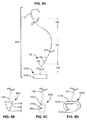
- FIG. 1A illustrates a self-retaining suture system 100.
- Self-retaining suture system 100 comprises needles 110, 112 attached to self-retaining suture thread 102.
- Self-retaining suture thread 102 includes a plurality of retainers 130 distributed on the surface of a filament 120.
- In lead-in section 140 of filament 120 there are no retainers 130.
- In section 142 of filament 120 there are a plurality of retainers 130 arranged such that the suture can be deployed in the direction of needle 110, but resists movement in the direction of needle 112.
- transition section 144 there are no retainers 130.
- Transition section 122 is, in some embodiments, provided with a marker to facilitate location of the transition section.
- Transition section 122 as shown, is provided with a visible band 122 to help identify the transition section.
- Markers are in some embodiments also provided on sections 142, 146 and/or needles 110, 112 in order to help identify the retainer location and orientation of a particular portion of self-retaining suture system 100.
- section 146 there is a plurality of retainers 130 arranged such that the suture can be deployed in the direction of needle 112, but resists movement in the direction of needle 110.
- the retainers 130 in section 146 are larger than the retainers 130 in section 142.
- the larger retainers are better suited for gripping tissue that is softer and/or less dense than the smaller retainers.
- lead-in section 148 of filament 120 there are no retainers 130.
- a break is shown in each of sections 140, 142, 144, 146 and 148 to indicate that the length of each section is, in some embodiments, varied and selected depending upon the application for which the suture is intended to be used.
- transition section 144 can be asymmetrically located closer to needle 110 or needle 112, if desired.
- a self-retaining suture having an asymmetrically located transition section 144 is, in some embodiments, favored by a physician that prefers to use his dominant hand in techniques that require suturing in opposite directions along a wound. The physician may start further from one end of the wound than the other and stitch the longer portion of the wound with the needle that is located further from the transition section 144. This allows a physician to use his dominant hand to stitch the majority of the wound with the longer arm of the suture.
- the longer arm of the suture is that section of suture between the transition section and the needle which is located further from the transition section.
- FIG. 1B illustrates a magnified view of self-retaining suture thread 102 in section 142.
- a plurality of retainers 130 is distributed on the surface of filament 120.
- the affixation of self-retaining sutures after deployment in tissue entails the penetration of retainer ends 132 into the surrounding tissue resulting in tissue being caught between the retainer 130 and the body of suture filament 120.
- the inner surface 134 of the retainer 130 that is in contact with the tissue that is caught between the retainer 130 and the body of filament 120 is referred to herein as the "tissue engagement surface” or "inner retainer surface.”
- each retainer 130 has a tip 132 and tissue retainer surface 134.
- a pledget can be applied to a self-retaining suture.
- FIG. 1H depicts a pledget 124 located in the transition zone 144 of self-retaining suture system 100.
- a pledget 124 can carry a marker/code 128 which helps identify the suture and/or properties thereof.
- Pledget 124 has one or more apertures 126 through which suture thread 120 can be passed as shown.
- a pledget can be bonded and/or mechanically fixed to suture thread 120, by, for example, welding, clipping, gluing, fusing.
- the pledget 126 can be used for locating the transition zone, for providing a stop so that the pledget can be pulled through tissue only until the pledget contacts the tissue, and/or for providing a support to tissue and organs, to name just a few uses.
- the pledget 126 can take many forms including a wider section that can support tissue.
- self-retaining sutures provide easier handling in anatomically tight or deep places (such as the pelvis, abdomen and thorax) and make it easier to approximate tissues in laparoscopic/endoscopic and minimally invasive procedures; all without having to secure the closure via a knot. Greater accuracy allows self-retaining sutures to be used for more complex closures (such as those with diameter mismatches, larger defects or purse string suturing) than can be accomplished with plain sutures.
- the superior qualities of self-retaining suture are particularly beneficial in endoscopic and telesurgical procedures. Self-retaining suture help overcome the limitations of dexterity and sensitivity present in endoscopic and telesurgical instruments.
- FIG. 1C shows an endoscopic suture delivery instrument 150 for delivering a self-retaining suture system 100 to a surgical site within a patient.
- Suture delivery instrument 150 includes, at the proximal end, a handle 152 connected by an elongated tubular member 154 to a spool 156.
- Handle 152 allows for positioning and operation of the suture delivery instrument 150 from outside of the body of the patient.
- Handle 152 may include one or more actuators 158 which is, in some embodiments, moved relative to one another and/or handle 152 for operating an effector, such as surgical scissors, a delivery spool, etc., located on the suture delivery instrument.
- Elongated tubular member connects handle 152 (proximal end) to spool 156 (distal end).
- Elongated tubular member 154 is a rigid member which is sized to fit through an access port into the body of the patient.
- the tubular member 154 is about or less than 12 mm, 8 mm and 5 mm.
- Elongated tubular member 154 must be long enough to reach the desired surgical site through the access port.
- elongated tubular member 154 is between 180 mm and 450 mm in length and is typically 360 mm in length for adults and 280 mm in length for pediatric surgery.
- the access port will be 12mm in diameter in less.
- the access port will be 10 mm in diameter or less.
- the access port is, in some embodiments, 8 mm or 5 mm in diameter or less. In general smaller access ports are preferred to reduce trauma to patient tissues however, the parts must be sufficiently large to permit entry of instruments having the functionality to perform the desired surgical manipulations.
- the diameter of the elongated tubular member 154 and spool 156 will be smaller than the inner diameter of the access port so that the distal portion of suture delivery instrument is, in some embodiments, introduce through the access port.
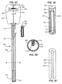
- FIG. 1D shows a cartridge 170 which includes spool 156 and a connector 172.
- Connector 172 allows cartridge 170 to be releasably attached to the distal end of elongated tubular member 154.
- an actuator 158 controls the attaching and releasing of the cartridge 170.
- a selection of sterile cartridges 170 is, in some embodiments, supplied for a procedure each supporting a different self-retaining suture.
- suture delivery instrument 150 can be used by the surgeon or assistant to select and deliver multiple self-retaining suture systems 100 in the course of a procedure.
- spool 156 is, in some embodiments, permanently fixed to the end of suture delivery instrument 150. As shown in FIG.
- spool 156 may also include one or more needle docks 157 for supporting the needles 110, 112 of self-retaining suture system 100.
- Needles 110, 112 are releasable attached to needle docks 157.
- the needle 110, 112 are removed from needle docks 157 to allow deployment of self-retaining suture thread 102.
- needles 110, 112 are replaced in needle docks 157 to allow removal of needles 110, 112 and any surplus self-retaining suture thread 102 after deployment of self-retaining suture thread 102.
- cartridge 170 includes a marker 174.
- marker 174 is a QR code.
- a QR code is a machine-readable matrix code or two-dimensional barcode designed to allow quick decoding of its contents.
- QR codes can be quickly recognized and decoded in camera images.
- the QR code in some embodiments directly identifies properties of the suture and in other cases identifies the location (URL or other) of data identifying properties of the suture.
- the properties of the suture are then displayed with the image of the surgical site provided to the surgeon (See FIG. 1G ). The information displayed allows the surgeon to verify that the cartridge is loaded with the desired suture.
- a QR code is shown in FIG.
- potential markers include, but are not limited to: markers visible in the visible light frequency range; alphanumeric markers, QR code markers, markers invisible to the naked eye but which can be visualized under the conditions of surgical use; markers recognizable in the non-visible radiation frequency range; markers detectable with ultrasound; markers which are machine readable; markers which are human readable; markers which is, in some embodiments, read remotely; markers which are active markers (including RFID); and markers which are passive markers (including passive RFID).
- the properties of the suture which can be associated with the marker include, but are not limited to: length, diameter, material, needles, presence of retainers, absence of retainers, source/brand and/or other fixed properties. In addition to fixed or static properties, a marker can be used to identify dynamic properties.
- movement of the cartridge and/or suture through forces being placed on the cartridge can cause the marker to move, and such movement can be noted by telesurgical system in order to track the changing location of the cartridge and the suture.
- Such movement can be translational movement or rotational movement.
- the amount of suture removed from the spool can be tracked.
- Markings placed additionally on the suture can be used to identify the changing location of the suture and also, for example, tension placed on the suture.
- the markings can also be used with a voice-command telesurgical system. The surgeon speaks the type of suture desired, and the telesurgical system then loads the cartridge onto the end of a tool located on an arm of the telesurgical system for deployment into a patient.
- FIG. 1E shows the distal portion of suture delivery instrument 150 introduced through an access port 160 into a patient 162.
- Suture delivery instrument 150 is inserted through a cannula 164 at the access port 160.
- Suture delivery instrument 150 is, in some embodiments, slid in and out of cannula 164 as shown by arrow 166.
- Suture delivery instrument 150 and cannula 164 may also pivot about the access port 160 as shown by arrows 168.
- suture delivery instrument 150 allows spool 156 to be delivered to a surgical site within patient 162.
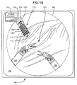
- FIG. 1F shows delivery of a self-retaining suture system 100 to a surgical site in a patient.
- an endoscope 180 illuminates the surgical site with one or more light sources 182.
- Endoscope 180 also images the surgical site through one or more imaging devices 184.
- Endoscope 180 thereby illuminates the surgical site.
- the dashed circle 186 indicates the field of view that is, in some embodiments, transmitted to the surgeon.
- suture delivery instrument 150 has been inserted so as to position a spool 156 of a cartridge 170 within the field of view.
- the end effectors (scissors, forceps and the like) of one or more endoscopic surgical instruments 190 also appear in the field of view.
- the surgeon may operate the endoscopic surgical instruments 190 to grasp the needles 110, 112 supported by spool 156. The surgeon may then operate the endoscopic surgical instruments 190 to deploy self-retaining suture thread 102 into tissue 192. After deployment of self-retaining suture thread 102, the surgeon may operate endoscopic surgical instruments 190 to replace needle 110, 112 in spool 156 and cut off any unused self-retaining suture thread 102. Suture delivery instrument 150 may then be removed from the surgical site thereby removing the needles and any excess self-retaining suture thread 102 from the patient's body.
- FIG. 1G shows an example of an image 194 on a display 196 of the surgical site of FIG. 1F as displayed to a surgeon.
- the dashed circle 186 indicates the field of view available from the endoscope (not shown).
- suture delivery instrument 150 has been inserted so as to position a spool 156 of a cartridge 170 within the field of view 186.
- Marker 174 of cartridge 170 is visible in the image.
- a computer system associated with display 196 identifies and translates marker 174.
- suture property information 176 associated with marker 174 is displayed to the surgeon in the image 194.
- the information displayed allows the surgeon to verify that the cartridge is loaded with the desired suture.
- the information displayed can be static or dynamic information.
- the image display system can also display other suture property information 176 relevant to the suture.
- tension sensed by the endoscopic tools or otherwise can be displayed as a percentage graph of the maximum rated tension of the identified suture.
- minimally invasive telesurgical systems have been developed to increase a surgeon's dexterity when working within an internal surgical site, as well as to allow a surgeon to operate on a patient from a remote location.
- the surgeon is provided with an image of the surgical site at a console. While viewing an image of the surgical site on a suitable display, the surgeon performs the surgical procedures on the patient by manipulating input devices of the console. The input devices control a robot arm which positions and manipulates the surgical instrument.
- the telesurgical system can provide mechanical actuation and control of a variety of surgical instruments or instruments having end effectors such as, e.g., tissue graspers, cautery, needle drivers, or the like, that perform various functions for the surgeon, e.g., holding or driving a needle, grasping a blood vessel, or dissecting tissue, or the like, in response to manipulation of the master control devices.
- end effectors such as, e.g., tissue graspers, cautery, needle drivers, or the like
- the Intuitive Surgical, Inc. DA VINCI® Surgical System is one example of a MIS telesurgical system.
- sutures in some embodiments be introduced to the surgical site using suture delivery instrument 150 previously described with respect to FIGS. 1C-1G .
- the suture delivery instrument could be operated manually by the surgeon. However, this requires the surgeon to leave the workstation.
- the suture delivery instrument 150 can be operated manually by a surgical assistant. However, this requires the assistant to insert the suture delivery instrument manually without the visualization provided by the workstation.
- a suture delivery instrument is provided which interfaces with the telesurgery system. The suture delivery instrument is used to deliver the self-retaining suture to the surgical site under the command of the surgeon.
- Such a suture delivery instrument advantageously leverages the abilities of the telesurgery system to accurately deliver the self-retaining suture to the surgical site under the control of the surgeon at the workstation and using the visualization capabilities of the telesurgery system. Moreover certain portions of the suture delivery operation is, in some embodiments, safely automated to facilitate the repeated delivery and extraction of sutures to the surgical site after initial setup under the control of the surgeon.
- the surgeon controls the suture delivery instrument with one or more inputs of the console, which can include, for example, switch, keyboards, motion controllers and/or voice input devices.
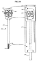
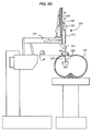
- FIG. 2A shows a suture delivery tool 250 suitable for use with a telesurgery system.
- Suture delivery tool 250 includes, at the proximal end, a case 252 connected by a tool shaft 254 to an end effector including a spool 256. Case 252 can be mounted to the interface 246 of a manipulator arm 240 to allow for positioning and operation of the suture delivery tool 250 from outside of the body of the patient.
- Suture delivery tool 250 includes a spool 256 mounted on the distal end of tool shaft 254.
- Spool 256 supports self-retaining suture system 100 thus allowing self-retaining suture system 100 to be delivered through a cannula/guide 264 to the surgical site within the patient.
- Spool 256 is sized so that it may slide through cannula/guide 264 into the body of the patient.
- Tool shaft 254 connects case 252 (proximal end) to the spool 256 (distal end).
- Tool shaft 254 is a rigid member which is sized to fit through an access port into the body of the patient. Alternatively, the tool shaft can be flexible. The tool shaft itself can be controlled by the telesurgical system so that the tool shaft can be "snaked" to a desired location. Tool shaft 254 must be long enough to reach the desired surgical site through the access port. The diameter of the tool shaft 254 and spool 256 must be small enough so that the distal portion of surgical tool 250 is, in some embodiments, introduced through the cannula tool guide/access port 264 into the patient.
- Tool shaft 254 may contain one or more mechanical linkages for transferring motion from the gears 258 in the case to an end effector at the distal end of tool shaft 254.
- FIG. 2A also shows the portion of a manipulator arm 240 to which a suture delivery tool 250 is, in some embodiments, mounted.
- the case 252 of suture delivery tool 250 (or another tool) is, in some embodiments, releasably mounted to the interface 246 on the manipulator arm 240.
- Case 252 includes one or more clips 253 which engage mating structures on interface 246 to hold case 252 to interface 246.
- interface 246 can be moved up and down track 247 to slide a tool in and out of cannula/tool guide 264. The movement of interface 246 along track 247 is effected by a transducer/actuator.
- Track 247 is sufficiently long that when interface 246 is moved to the proximal end of the track (the end furthest from the patient) a suture delivery tool 250 mounted to the interface is completely retracted from the cannula/tool guide 264.
- a suture delivery tool 250 is, in some embodiments, mated with or released from interface 246 when interface 246 is at the proximal end of the track.
- the suture delivery tool 250 may then be inserted through access port 264 using the transducer/actuator to advance interface 246 along track 247 towards the access port 264.
- case 252 of suture delivery tool 250 may include one or more gears 258 to control movement/operation of portions of the suture delivery tool 250.
- Interface 246 includes a plurality of powered gears 248 which mesh with the plurality of gears 258 in case 252 when case 252 is mounted to interface 246. This allows the powered gears 248 of the interface to be utilized to rotate tool shaft 254 and/or spool 256 and/or operate other mechanical operations of the suture delivery tool.
- suture delivery tool 250 in some embodiments includes at its distal end a grasper for grasping needles for removal from the patient or a cutter for cutting suture during the procedure; the grasper or cutter is, in some embodiments, operated by the powered gears 248 through the mating gears 258 of case 252.
- FIGS. 2B and 2C show a suture delivery tool 250 mounted to a manipulator arm 240.
- the case 252 is held to interface 246 by one or clips 253 (not shown).
- One or more release levers 257 are accessible when case 252 is mounted to interface 248 to release clips 253 (not shown) when desired.
- Spool 256 is, in some embodiments, permanently attached to suture delivery tool 250 or may form part of a cartridge which is, in some embodiments, releasably attached to suture delivery tool 250. In some embodiments the spool is permanently or releasably attached at a fixed location of the suture delivery tool 250. Spool 256 is fixed (in this example) at the distal end of suture delivery tool 250.
- the interface 246 is first moved to the proximal end of the track 247 (the end furthest from the patient).
- the case 248 of the suture delivery tool 250 carrying the spool 256 is then mated with the interface 246 of the manipulator arm 240 as shown in FIG 2B .
- the interface 246 is then advanced linearly towards the patient down the track 247.
- the movement of the interface 246 down the track 247 inserts the spool 256 and the self-retaining suture 100 through the cannula/tool guide 264 into the patient as shown in FIG. 2C .
- the self-retaining suture 100 may then be positioned at the surgical site within the patient by the manipulator arm 240.
- the self-retaining suture 100 is positioned to be removed from the spool 256 by another instrument.
- the needles and surplus suture are reattached to the spool after deployment of the suture.
- the suture delivery tool delivery tool 250 and spool 256 (and optionally the needles and excess suture) are removed from the body by retracting the interface 246 to the proximal end of the track 247 (the end furthest from the patient) as shown in FIG 2B . If another suture is required, the suture delivery tool 250 is exchanged for another suture delivery tool, or a cartridge including the spool 256 is removed and replaced with a new cartridge having a new spool 256.
- FIG. 2D shows a view of manipulator arm 240 with the distal portion of suture delivery tool 250 introduced through an incision 260 into a patient 262.
- Suture delivery tool 250 is inserted through a cannula 264 at the incision 260.
- the cannula 264 is coupled to the manipulator arm 240.
- the suture delivery tool 250 is releasably mated with the interface 246 on the manipulator arm 240.
- the manipulator arm 240 can position the suture delivery tool 250 and spool 256 in three dimensions and rotate the suture delivery tool 250 about the insertion axis while constraining the motion (preventing lateral displacement) at the incision 260.
- Suture delivery tool 250 is slid in and out of cannula 264 as shown by arrow 266.
- Suture delivery tool 250 and cannula 264 is adapted to be pivoted about the incision 260 as shown by arrows 268, 269.
- the movements of the suture delivery tool in three or more dimensions within patient 262 are thus under the control of manipulator arm 240 allowing the spool 256 and suture 100 to be delivered to a desired position in the operative site and/or within the field of vision of the surgeon.
- FIGS. 2E and 2F show an example of a telesurgical system 200 which includes a plurality of manipulator arms 240 one of which can be used to position the suture delivery tool 20 within a patient.
- FIG. 2E shows a perspective view of the telesurgical system whereas FIG. 2F shows a functional block diagram of the telesurgical system 200.
- telesurgical system 200 comprises a patient-side manipulator system 204 and a surgeon's console 201.
- Patient-side manipulator system 204 includes a plurality of manipulator arms 240 mounted on an adjustable stand 242.
- the manipulator arms 240 comprise a plurality of mechanical linkages and a plurality of transducers/actuators.
- the transducers/actuators are, in some embodiments, electrical motors, for example, stepper motors and/or servo motors.
- the actuators are pneumatic, hydraulic, magnetic or other transducers capable of effecting movement of the linkages in response to control signals.
- the position of the linkages is monitored using a plurality of sensors 270; e.g. linear or rotary optical encoders.
- the linkages are adapted to be moved independently by a plurality of actuators 272; e.g. stepper motors and shape-memory actuators.
- the actuators 272 may also be sensors 270; for example, stepper motors function as actuators, position encoders and force sensors.
- a patient-side manipulator system 240 in some embodiments includes two mechanical manipulator arms 240 for operating surgical tools and one manipulator arm 240 for positioning the endoscope.
- a suture delivery tool is in this embodiment positioned and operated by one of the two manipulator arms 240 for operating surgical tools.
- a suture is in some cases inserted with the suture delivery tool 250 and then the suture delivery tool exchanged for another surgical tool such as a needle driver or grasper.
- a fourth arm is provided. In such systems the suture delivery tool is positioned and operated by the fourth manipulator arm. The surgeon can switch between control of the surgical instruments and control of the suture delivery tool without the need for exchange of the suture delivery tool with a surgical instrument.
- Surgeon's console 201 comprises a display system 212, a control system 214 and a processing system 218.
- the display system 212 includes a 2D or 3D video display 213 and one or more of an audio output system, force-feedback system, touchscreen display and other display elements e.g. lights, buzzers etc.
- the display system 212 provides the surgeon 202 with an image of the surgical site and may also provide other information in visual, audible and/or haptic formats.
- the control system 214 may include one or more of a variety of input devices; for example hand-operated controllers 215, joysticks, gloves, keyboards 216, buttons, case-pedals 217, touchscreen displays, mice and the like.
- a microphone may also be provided so that the surgeon can provide voice commands to the control system.
- Particular components are elements of both display system 212 and control system 214; for example, force-feedback hand controllers and touchscreen displays which both display information and receive input.
- the surgeon 202 performs a minimally-invasive surgery procedure by manipulating control devices of the control system 214.
- the output of the control system 214 is received by a processing system 218.
- One function of processing system 218 is to translate the output of the control system 214 into control signals for the operation of the patient-side manipulator system 204.
- Surgeon's console 201 is connected by cable 206 to patient-side manipulators 240 and 242.
- the operation of the control devices by the surgeon 204 operates the patient-side manipulator system 204 and manipulator arms 240 to position and operate surgical tools and an endoscope coupled to the manipulator arms 240.
- the movement of the surgical tools is imaged by the endoscope and the image of the surgical tools is transmitted to the processing system 218.
- the processing system transforms the image of the surgical tools and transmits it (and other information) to display system 212 so that it can be observed by the surgeon 202.
- FIGS. 3A and 3B show an alternative suture delivery tool 350 mounted to a manipulator arm 240.
- Suture delivery tool has a load slot 310 for receiving a cartridge 320 including a spool 356.
- Cartridge 320 is sized and configured to fit through load slot 310 into the tool shaft 354 as shown in FIG. 3A .
- Suture delivery tool 350 has a transport mechanism 312 for moving cartridge 320 from the loading slot 352 to the distal end of suture delivery tool 350 where it is accessible through delivery slot 314 for removal of the suture 100.
- the driven gears 248 of a manipulator arm 240 operate the transport mechanism through mating gears (not shown) in the case 352.
- the transport mechanism 312 is for example a cable drive screw drive or similar drive for moving a cartridge linearly through the tool shaft 354.
- the distal end of the suture delivery tool 350 is first positioned at the surgical site under surgeon control.
- Cartridge 320 is then loaded into the loading slot 310 of the suture delivery tool 350.
- the transport mechanism 312 is then operated to move the cartridge 320 from the loading slot 310 to the delivery slot 314 at the distal end of suture delivery tool 350 as shown by arrow 317.
- cartridge 320 reaches the distal end of suture delivery tool 350, cartridge 320 is exposed sufficiently at delivery slot 314 that the suture and needles are exposed to be accessed and removed from the cartridge 320 as shown in FIG 3B .
- the self-retaining suture 100 is then removed from the cartridge 320 by another surgical instrument at the surgical site.
- the spool 356 can be rotated at the delivery slot 314 in order to remove the suture from the spool.
- the needles and surplus suture are re-attached to cartridge 320 after deployment of the self-retaining suture 100.
- the cartridge 320 is then removed from the body by operating the transport mechanism 356 in the opposite direction to retract the cartridge 320 from the delivery slot 314 to the loading slot 310 where the cartridge 320 is positioned to be removed and replaced with a new cartridge 320.
- one or more cartridges 320 are delivered through suture delivery tool 350 automatically.
- the automatic delivery of cartridges is rendered safe by the fact that the cartridge 320 stays within the confines of the suture delivery tool 350. Additionally, the suture delivery tool itself does not change position during automatic delivery of the cartridge (only the cartridge is moved). Once the suture delivery tool has been positioned under surgeon guidance, there is little or no possibility of the insertion or retraction of a new cartridge 320 causing damage to tissue at the surgical site. Thus the presentation and removal of suture cartridges 320 is performed automatically or by the surgeon's assistant without the need to check the position for delivery of subsequent cartridge deliveries.
- FIG. 3C shows one embodiment of a suture delivery tool 350 which is adapted to move a cartridge 320 from a proximal end of the shaft 354 to the distal end of the shaft 354.
- FIG. 3D shows a section through the tool shaft 354.
- FIGS. 3E and 3F show views of one embodiment of a cartridge for use with suture delivery tool 350 of FIG. 3C.
- FIG. 3C shows interior components of case 352 and tool shaft 354.
- transport mechanism comprises a threaded rod 316 which runs the length of tool shaft 354.
- the threaded rod 316 is supported at each end by a bushing which allows rotation of the threaded rod.
- a capstan 360 within case 352 is directly connected to a gear of case 352 which is adapted to be mated with a driven gear of the interface of the manipulator arm.
- a transmission mechanism transmits rotation of capstan 360 to rotation of threaded rod 316.
- the transmission mechanism is, in some embodiments, a geared mechanism or may comprise a pulley-driven system as shown in FIG. 3C .
- a loop of cable 364 is wrapped around capstan 360 and idler pulley 364 between capstan 360 and idler pulley 364, cable 364 is also wrapped around a pulley 366 mounted to threaded rod 316.
- Threaded rod 316 When cartridge 320 is engaged with threaded rod 316, rotation of threaded rod 316 results in movement of the cartridge up or down tool shaft 354 depending on the direction of rotation of the threaded rod 316. Threaded rod 316 can be rotated in one direction to move cartridge 320 from the load slot 310 to the delivery slot 316. Threaded rod 316 can be rotated in the opposite direction to move cartridge 320 from the delivery slot 316 back to the load slot 310 where it can be removed/replaced. Note that in some embodiments, what is shown as a cartridge in FIG. 3C is a shuttle which is an integral part of the suture delivery tool 350. In such embodiments, rather than removing and replacing a cartridge, sutures are loaded and unloaded from the shuttle to be transported to or from the distal end of the suture delivery tool 350.
- FIG. 3D shows a sectional view through shaft 354 along the line D-D of FIG. 3C .
- the position of a cartridge 320 within the shaft is shown by the dashed line. Note that the interior of groove 322 is pushed against and engaged with threaded rod 316. Note also that shaft 354 has an internal ridge 318 which also engages groove 322 to prevent rotation of cartridge 320.
- FIGS. 3E and 3F show one embodiment of a cartridge 320 suitable for use with the suture delivery tool 350 of FIGS. 3C and 3D .
- cartridge 320 comprises a cylinder several centimeters long and having a diameter slightly less than the interior diameter of shaft 354.
- Cartridge 320 has a groove 322 in the back surface. Groove 322 is sized to fit over the threaded rod 316 and ridge 318 of suture delivery tool 350.
- Groove 322 has surface features 324 for engaging threaded rod 316.
- Surface features 325 include, for example, threads, ridges or similar contact points which can engage threaded rod 316 to cause linear motion of cartridge 320.
- Cartridge 320 has an opening 321 on the front surface through which a self-retaining suture 100 is loaded into the hollow chamber 326.
- Hollow chamber contains needle docks 328 for releasably securing needles 110, 112 of self-retaining suture 100.
- Suture thread 102 is positioned linearly within hollow chamber 326 passing around pin 329 to hold self-retaining suture 100 in position during transfer. Where longer suture is required self-retaining suture 100 is coiled up with cartridge 320.
- Cartridge 320 may additionally comprise more needle docks and nubs so that cartridge 320 can hold two or more self-retaining sutures 100.
- FIGS. 4A through 4G show various suture cartridges suitable for use with MIS suture delivery tools in accordance with embodiments of the present invention.
- the cartridge should have a diameter less than the diameter of the access port i.e. typically the cartridge should be 10 mm in diameter or less.
- the cartridge length will be determined by the amount of suture to be contained.
- the cartridges will preferably be a fraction of the length of the suture delivery tool.
- the cartridges will preferably be 120 mm or less in length and more preferably 80 mm or less in length. In some circumstances, the cartridges are 10 mm or less in length.
- the cartridge should also have a coupling, aperture groove or the like for attaching the cartridge to the suture delivery tool or engaging the drive mechanism of the suture delivery tool.
- Each of the cartridges and spools discussed herein is adaptable for use with each of the suture delivery tools discussed herein by addition of the appropriate mating features for engaging the suture delivery tool.
- FIG. 4A shows a cartridge 410 comprising a spool 412 having a helical groove 414.
- self-retaining suture 100 is wrapped around spool 412 within helical groove 414.
- the cartridge includes a mechanism for preventing tangling of the suture or self-retaining suture.
- the retainers of section 142 facing in a given direction are spaced apart from the retainers of section 146 facing in an opposing direction (and which is separated from section 142 by transitional segment 144).
- the self-retaining suture 100 is, in some embodiments, wrapped sufficiently tightly around spool 412 that the retainer pluralities do not overlap with one another; for example, needles 110 and 112 at either end of self-retaining suture 100 are, in some embodiments, removably engaged in needle parks 416 and 417, respectively, in order to achieve such tension.
- cartridge 410 has a central aperture 418 for mounting cartridge on a pin on the end of a suture delivery tool (for example suture delivery tool 150 of FIG. 1C or suture delivery tool 250 of FIG. 2A .
- the aperture is provided with a latching mechanism such that the pin is releasably retained within aperture 418 while still allowing rotation of cartridge 410 during removal of self-retaining suture 100.
- FIG. 4B shows a partial cutaway view of a variation of cartridge 410 of FIG 4A .
- the spool 412 is provided with a cover 430 which fits over the spool 412, holding suture 100 within groove 414.
- Suture 100 can be removed by sliding cover 430 off spool 412 (incrementally or in one go).
- cover 430 is made of a material that can be split by the suture as the suture 100 is unwound.
- Cover 430 may, for example, be perforated along the groove 414 so that suture 100 is adapted to be pulled through the cover 430 as it is unwound from the spool 412.
- Such a cover may also be used with other cartridges described herein.
- a cover is useful to protect the suture during delivery to the surgical site and to retain the suture within the cartridge during delivery.
- the cover is removed by the surgeon using another surgical instrument.
- the cover is removed by actuation of the suture delivery tool to which the cartridge is mated.
- self-retaining suture 100 is wrapped around spool 422 within double helical grooves 424.
- the retainers of section 142 facing in a given direction are spaced apart from the retainers of section 146 facing in an opposing direction (and which is separated from section 142 by transitional segment 144).
- the self-retaining suture 100 is, in some embodiments, wrapped sufficiently tightly around spool 422 that the retainer pluralities do not overlap with one another.
- needles 110 and 112 at either end of self-retaining suture 100 are, in some embodiments, removably engaged in needle parks 426 and 427 and transitional segment 144 can be wrapped around pin 423, respectively, in order to achieve such tension.
- cartridge 420 has a central protrusion 428 for mounting cartridge on the end of a suture delivery tool, for example, suture delivery tool 150 of FIG. 1C or suture delivery tool 250 of FIG. 2A .
- the protrusion is provided with a latching mechanism 429 such that the protrusion is releasably retained within a suture delivery tool while still allowing rotation of cartridge 420 during removal of self-retaining suture 100.
- Groove 414 or grooves 424 are, in some embodiments, provided with retaining features to releasably retain self-retaining suture 100 to manage self-retaining suture 100 while it is being unwound form a spool.
- the groove is shaped so that the adjacent walls of the grooves are approximately parallel and slightly closer together than the diameter of the suture 100. The walls thus serve to keep suture 100 in the groove even when the tension in suture 100 is released.
- the walls are flexible enough that they can be pushed apart with a slight force to admit and release suture 100 as it is being wound on or off of the spool.
- This configuration of helical groove forms what is essentially a continuous helical clip which lightly holds suture 100 to the surface of the spool.
- Other configurations of groove and clips are used in alternative embodiments to hold suture 100 in place.
- releasable clips are positioned intermittently along the helical groove.
- a releasable adhesive or gel is provided continuously or intermittently along the helical grove to retain suture 100 in the absence of tension.
- the spools of the various embodiments herein hold the sutures so as not to compress or reposition the retainers.
- the retainers on the suture are proud. That is, the retainers stand out or away from the body of the suture.
- the retainers In a container or cartridge such as a spool, it may be desirable that the retainers to remain away from the body of the suture and not be compressed against the body of the suture. Further, it is to be understood that some materials such as polymers, that the suture body is made up can have a memory. That is to say, the suture can develop a set shape after being help in a certain shape for awhile, such as being held in a container. With a spool, the suture can be set or have a memory of a suture with many small loops. This can be advantageous in a situation where tight radius suturing is desirable.
- the suture With the suture set with tight loops, the suture can be managed as the suture is in a coil and the tight loops of the suture help facilitate sewing tissue with tight radius stitches.
- drug can be coated on the internal surfaces of the cartridges such that as the suture is removed from the cartridges, drugs coated on the surfaces of the helical grooves, for example, can rub off onto the suture for delivery to the tissue.
- Cartridges 410 and 420 are preferably 10 mm or less in diameter so that they may fit through a cannula/guide into a patient.
- the length of cartridges 410, 420 may vary depending upon the length of self-retaining suture 100 and the number of turns of the groove required to hold self-retaining suture 100. For example, if spools 412, 422 are 10 mm in diameter, approximately 30 mm of suture will be taken up by one wrap around the spool. Thus, a suture of 70 mm total length will require less than three turns of groove around the spool. A suture of 140 mm total length will require less than five turns of groove around the spool.
- a suture delivery tool 450 includes a spindle 452.
- a plurality of cartridges 454 each holding a self-retaining suture 100 including needles is received over spindle 452.
- Each cartridge 454 has a central aperture 455 which fits over spindle 452.
- Spindle 452 has at its distal end a catch 456 for releasably retaining the plurality of cartridges onto the spindle 452 during use. Additional catches 456 is, in some embodiments, provided along the length of spindle 452 so that less than the maximum number of cartridges is, in some embodiments, securely held on the spindle 452.
- FIGS. 4F and 4G show two partial cutaway views of a suture cartridge 460 suitable for use with MIS suture delivery tools.
- self-retaining suture 100 is arranged in a linear configuration.
- the linear configuration is suitable for shorter sutures which are often used in MIS surgery.
- self-retaining suture 100 is, in some examples, approximately 70 mm in total length with each of sections 142 and 146 being approximately 35 mm in length.
- Cartridge 460 would be approximately 40 mm in length to accommodate the 70 mm suture in the configuration of FIG 4F .
- self-retaining suture 100 is approximately 140 mm in total length with each or sections 142 and 146 being approximately 70 mm in length.
- Cartridge 460 would be approximately 80 mm in length to accommodate the 140 mm suture in the configuration of FIG 4F .
- cartridge 460 is approximately cylindrical and has a projection 462 on its proximal end for releasably engaging a suture delivery tool.
- Cartridge 460 has an opening 464 at its distal end for allowing access to the interior of cartridge 460.
- a self-retaining suture 100 is contained with cartridge 460 with needles 110 and 112 releasably secured adjacent opening 464 by needle docks 466.
- a longitudinal divider 467 separates sections 142 and 146 of self-retaining suture 100.
- Section 144 of self-retaining suture 100 passes through a slot 468 in divider 467.
- Self-retaining suture 100 can be pulled along/through slot 468 towards opening 464.
- Slot 468 is open with opening 464 allowing self-retaining suture 100 to be released from the cartridge 460.
- the cartridge 460 may include several different sutures in similar configurations and spaced from one another by dividers or the like. As shown in FIG. 4H , multiple loops of suture 100 are separated from one anther by dividers 472 so that each suture is, in some examples, removed individually from a cartridge. The stacked sutures may then be loaded into a suture cartridge 470. Cartridge 470 has sufficient needle docks for each of the needles of the sutures. In use, the surgeon may remove one suture and its associated needles at a time without disturbing the other sutures 100.
- a suture delivery tool in a telesurgery system.
- telesurgery where telesurgery is to be performed at a remote location, there is, in some embodiments, no patient-side assistant to load cartridges onto a suture delivery system.
- a suture cartridge magazine holds a plurality of suture cartridges.
- a selector mechanism allows a surgeon to select a cartridge to be loaded into a suture delivery tool from the cartridges available in the magazine.
- a cartridge load/unload mechanism loads the cartridge onto/into the suture delivery tool and unloads the cartridge after deployment of the suture. This allows the surgeon to choose a suture and deploy it to the surgical site using the surgeon's console controls without the use of an assistant.
- FIGS. 5A-5C show a suture cartridge magazine 500 which is adapted to select, load and unload cartridges 520 into a suture delivery tool 550 mounted to a manipulator arm 540.
- the case 552 of suture cartridge magazine 500 is releasably mounted to the interface 546 on the manipulator arm 540.
- Magazine 500 is, in this embodiment, mounted to interface 546 adjacent a load slot 522 in suture delivery tool 550.
- magazine 500 is in a fixed position relative to suture delivery tool 550.
- magazine 500 is, in some embodiments, mounted in an affixed position relative to manipulator arm 540. In such case, the suture delivery tool retracts to place the distal end of the tool in position for loading and is then advanced into the patient.
- a support 502 is mounted to interface 546.
- Support 502 carries a selector mechanism 504 and a load/unload mechanism 506.
- Magazine 500 is hooped shaped an has a plurality of spring loaded bays 508 each of which is adapted to releasably secure a cartridge. The number of bays can be selected based on the needs of the system.
- the bays 508 are open towards the interior and exterior of the magazine.
- a cover 510 substantially covers the magazine 500 such that only one bay 508 is exposed at an opening 512 at any time.
- the bays can rotate with respect to cover 510 so that any one of the bays 508 is, in some embodiments, adjacent the opening 512. Magazine 500 mounts to support 502 such that opening 512 in cover 510 is adjacent to suture delivery device 550.
- Selector mechanism 504 engages magazine 500 such that it rotates bays 508 past opening 512 and suture delivery tool 550 as shown by arrow 514 of FIGS. 5A and 5B .
- Selector mechanism 504 may rotate bays 508 passed opening 512 for sequential loading of cartridges 520.
- cartridges 520 is, in some embodiments, loaded with different sutures, it is, in some embodiments, desirable to allow selectable loading and unloading of any one of the cartridges.
- Data regarding the sutures is, in some embodiments, entered into the system manually upon loading the magazine, or more preferably, each cartridge comprises a machine readable device, such as a barcode or RFID tag, which identifies the suture loaded on the cartridge.
- the system can thus automatically determine the sutures available in a magazine and the position of the respective cartridges in the magazine by reading each machine readable device in sequence when the magazine is loaded.
- the surgeon's console should display data regarding the sutures available in cartridges available in the magazine to the surgeon and allow the surgeon to select a suture for use in the procedure.
- selector system 504 indexes magazine 500 until the desired cartridge 520 is positioned adjacent opening 512 and suture delivery tool 550.
- the selector system 504 is preferably operated by one or more transducers/actuators controlled by the surgeon from the surgeon's console.
- selector system 504 may coupled to a driven gear 248 (See FIG. 2A ) of interface 546.
- load/unload mechanism 506 When the desired cartridge 520 is positioned adjacent opening 512 and suture delivery tool 550, load/unload mechanism 506 is activated to push the cartridge 520 from the spring-loaded bay 508 through opening 512 and into the load slot 522 of the suture delivery tool 550 (see arrow 516 in FIG 5C ).
- the transport mechanism of the suture delivery tool can then be activated to transport cartridge 520 to the distal end of suture delivery tool 550 for deployment of the suture. After deployment, cartridge 520 is transported back to the load slot of suture delivery tool 550.
- Load/unload mechanism 506 is then activated to pull cartridge 520 from the load slot into the spring-loaded bay 508.
- a new suture may then be selected by the surgeon and the cartridge indexed and loaded automatically in response to the suture selected by the surgeon.
- the load/unload mechanism 506 is operated by one or more transducers/actuators controlled by the surgeon from the surgeon's console. In some embodiments load/unload mechanism 506 may coupled to a driven gear 248 (See FIG. 2A ) of interface 546.
- suture delivery systems described herein are, in some embodiments, utilized for the delivery of plain sutures.
- suture delivery systems are, in various embodiments, used for the delivery of self-retaining sutures in a wide variety of configurations including unidirectional self-retaining sutures, unidirectional self-retaining sutures having an anchor at one end and a needle at the other end; and/or bidirectional self-retaining sutures as discussed herein.
- FIG. 6A illustrates an alternative example of a self-retaining suture system 600.
- Self-retaining suture system 600 includes needle 110 and sections 140, 142 and 144 of self-retaining suture system 100 of FIG. 1A .
- self-retaining suture system 600 is a single-armed system.
- filament 120 terminates following section 144 in a tissue anchor 602a.
- Tissue anchor 602a is a device for engaging tissue and preventing filament 120 from moving through tissue in the direction of needle 110.
- Tissue anchor 602a is in some examples formed in one piece with filament 120 or formed separately and subsequently attached to filament 120. As shown in FIG.
- tissue anchor 602a has a bar-shaped body 610a which extends approximately perpendicular to the axis of filament 120.
- Bar-shaped body 610a is sufficiently long and stiff to preclude movement of the distal end of filament 120 in the direction of needle 110 after tissue anchor 602a has engaged a tissue.
- FIG. 6B shows an alternative anchor 602b which could be used in place of tissue anchor 602a of FIG. 6A .
- tissue anchor 602b comprises a conical body 610b.
- Conical body 610b has a pointed end 612b and tissue engaging features 614b which consist of ribs and/or barbs.
- Tissue anchor 602b is configured to be pushed into tissue in order to anchor filament 120 to that tissue and preclude movement of the distal end of filament 120 in the direction of needle 110.
- FIG. 6C shows an alternative tissue anchor 602c which could be used in place of tissue anchor 602a of FIG. 6A .
- tissue anchor 602c comprises a loop 610c.
- Loop 610c is, in this example, formed by folding back the end 612c of filament 120 and securing end 612c to filament 120 by welding, fusing and/or adhesive. Loop 610c is thus formed from the material of filament 120.
- Loop 610c has an aperture 614c through which needle 110 can pass in order to create a noose/cinch which can be used to engage tissue and preclude movement of the distal end of filament 120 in the direction of needle 110.
- FIG. 6D shows an alternative tissue anchor 602d which could be used in place of tissue anchor 602a of FIG. 6A .
- tissue anchor 602d comprises a staple-shaped body 610d.
- Filament 120 passes through an aperture in anchor 602d and is secured by a crimp 614d.
- Staple-shaped body 610d has two pointed ends 612d which can be pushed into tissue and deformed towards each other to engage the tissue and preclude movement of the distal end of filament 120 in the direction of needle 110.
- FIGS. 6E and 6F show an exploded and partial cutaway views of a suture cartridge 660 suitable for use with MIS suture delivery tools.
- Cartridge 660 can be used to releasably hold one or more unidirectional self-retaining suture 600 with an anchor 602a-d such as described in FIGS. 6A-6D .
- one or more self-retaining suture systems 600 is arranged in a linear configuration. The linear configuration is suitable for shorter sutures which are often used in MIS surgery.
- self-retaining suture system 600 is, in some examples, approximately 70 mm in total length.
- Cartridge 660 would be approximately 70 mm in length to accommodate the 70 mm suture in the configuration of FIG 6E . As shown in FIGS.
- cartridge 660 is approximately cylindrical and has a projection 662 on its proximal end for releasably engaging a suture delivery tool.
- Cartridge 660 has an opening 664 at its distal end for allowing access to the interior of cartridge 660.
- one or more self-retaining suture system 600 can be contained within cartridge 660 with needles 110 releasably secured adjacent opening 664 by needle docks 666.
- Anchors 602a-d of self-retaining suture systems 600 are positioned towards the proximal end of the cartridge 660.
- Multiple self-retaining suture systems 600 are, in some examples, loaded in a cartridge 660. As shown in FIG. 6E the self-retaining suture systems 600 are stacked and loaded through opening 664. Where multiple self-retaining suture systems 600 are loaded in a cartridge 600 they can be spaced from one another by dividers or the like to prevent entanglement. Cartridge 670 of FIG. 6G and/or dividers 669 have sufficient needle docks 667 for each of the needles 110. As shown in FIGS. 6E and 6F , multiple self-retaining suture systems 600 are separated from one another by dividers 669. Each of the plurality of self-retaining suture systems 600 can be, in some embodiments, removed individually from a cartridge 670.
- Cartridge 660 containing one or more self-retaining suture system 600 can be mounted to an endoscopic suture delivery tool as previously described for delivery of self-retaining suture systems 600 through a port to a desired location within a patient's body.
- the surgeon may remove one self-retaining suture system 600 and its associated needle 110 and anchor 602a-d without disturbing the other self-retaining suture systems 600.
- FIG. 6G shows a cartridge 670 which includes spool 656 and a connector 672.
- Connector 672 allows cartridge 670 to be releasably attached to the distal end of a tool such as an endoscopic tool.
- Spool 656 includes a spiral groove 658 for releasably holding a unidirectional self-retaining suture 600 with an anchor 602a-d such as described in FIGS. 6A-6D .
- spool 656 also includes one or more needle docks 657 for supporting the needle 110 of self-retaining suture system 600. Needle 110 is releasable attached to needle dock 657. The needle 110 is removed from needle dock 657 to allow deployment of self-retaining suture system 600. In some embodiments, needle 110 is replaced in needle dock 657 to allow removal of needle 110 and any surplus self-retaining suture thread after deployment of self-retaining suture system 600.
- FIG. 6H shows cartridge 670 attached to the elongated member 682 of an endoscopic instrument 680 for insertion through a port into the body of a patient.
- a selection of sterile cartridges 670 is, in some embodiments, supplied for a procedure each supporting a different self-retaining suture system 100, 600.
- endoscopic suture delivery instrument 680 can be used by the surgeon or assistant to select and deliver multiple self-retaining suture systems 100, 600 in the course of a procedure.
- Handle 684 can be manipulated by a surgeon outside the body of a patient to deliver spool 656 to a desired site within the patient.
- an actuator 686 is provided to control the attaching and releasing of the cartridge 670.
- spool 656 is fixed to the end of suture delivery instrument 680.
- cartridge 670 can also be delivered by a robotically-operated endoscopic tool as shown for example in FIG. 3A .
Landscapes
- Health & Medical Sciences (AREA)
- Life Sciences & Earth Sciences (AREA)
- Surgery (AREA)
- Engineering & Computer Science (AREA)
- Veterinary Medicine (AREA)
- Heart & Thoracic Surgery (AREA)
- Animal Behavior & Ethology (AREA)
- General Health & Medical Sciences (AREA)
- Public Health (AREA)
- Biomedical Technology (AREA)
- Medical Informatics (AREA)
- Molecular Biology (AREA)
- Nuclear Medicine, Radiotherapy & Molecular Imaging (AREA)
- Robotics (AREA)
- Pathology (AREA)
- Oral & Maxillofacial Surgery (AREA)
- Dentistry (AREA)
- Physics & Mathematics (AREA)
- Electromagnetism (AREA)
- Pulmonology (AREA)
- Anesthesiology (AREA)
- Hematology (AREA)
- Biophysics (AREA)
- Surgical Instruments (AREA)
- Materials For Medical Uses (AREA)
- Endoscopes (AREA)
Description
- The present invention relates to systems for packaging, selecting and delivering sutures to surgical sites within a patient during surgical procedures including minimally-invasive surgical procedures.
- Minimally invasive surgery (MIS) procedures avoid open invasive surgery in favor of closed or local surgery with less trauma. Minimally invasive surgical procedures typically involve remote manipulation of instruments with indirect observation of the surgical field through an endoscope or similar device, and are carried out through a small access port through the skin or through a body cavity or anatomical opening. Minimally invasive medical techniques thereby reduce tissue damage during diagnostic or surgical procedures, thereby reducing patient recovery time, discomfort, and deleterious side effects. Minimally invasive medical techniques consequently shorten the average length of a hospital stay for a procedure when compared to standard open surgery.
- One form of minimally invasive surgery is endoscopy. Probably the most common form of endoscopy is laparoscopy, which is minimally invasive inspection and surgery inside the abdominal cavity. In standard laparoscopic surgery, a patient's abdomen is insufflated with gas, and cannula sleeves are passed through small (approximately 13 mm [½ inch]) incisions to provide access ports for laparoscopic surgical instruments. The laparoscopic surgical instruments generally include an endoscope for visualizing the surgical field and specialized surgical instruments which is, in some embodiments, passed through the access ports. The instruments can include clamps, graspers, scissors, staplers, and needle holders, for example. The surgical instruments may or may not be similar to those used in conventional (open) surgery; typically that the working end of each instrument is separated from its handle by an elongated shaft and is sized and configured to fit through the access port. To perform surgical procedures, the surgeon passes the surgical instruments through the access ports to an internal surgical site and manipulates them from outside the abdomen. The surgeon monitors the procedure by means of a monitor that displays an image of the surgical site taken from the laparoscope. Similar endoscopic techniques are employed in, e.g., arthroscopy, thoracoscopy, retroperitoneoscopy, pelviscopy, nephroscopy, cystoscopy, cisternoscopy, sinoscopy, hysteroscopy, urethroscopy, craniotomy, and natural orifice surgery (for example of the airway and gastrointestinal tract).
- There are many disadvantages relating to MIS technology utilizing hand-operated instruments. For example, existing MIS instruments deny the surgeon the flexibility of instrument placement found in open surgery. Most current laparoscopic instruments have rigid shafts, so that it can be difficult to approach the surgical site through the small incision. Additionally, the length and construction of many endoscopic instruments reduces the surgeon's ability to feel forces exerted by the instrument on tissues and organs at the surgical site. The lack of dexterity and sensitivity of endoscopic instruments is an impediment to the expansion of minimally invasive surgery.
- Minimally invasive telesurgery systems have been developed to increase a surgeon's dexterity when working within an internal surgical site, as well as to allow a surgeon to operate on a patient from a remote location. In a telesurgery system, the surgeon is provided with an image of the surgical site as with endoscopy. However, rather than manipulating the surgical instruments directly, the surgeon performs the surgical procedures on the patient by manipulating master input or control devices at a console. The master input and control devices control the motion of surgical instruments utilizing telemanipulators. Depending on the system, telesurgery systems may overcome some but not all of the lack of dexterity and sensitivity of endoscopic instruments. Surgical telemanipulator systems are often referred to as robotic or robotically-assisted surgery systems.
- Many MIS procedures including MIS telesurgery procedures employ wound closure devices such as sutures, staples and tacks for closing wounds, repairing traumatic injuries or defects, joining tissues together (bringing severed tissues into approximation, closing an anatomical space, affixing single or multiple tissue layers together, creating an anastomosis between two hollow/luminal structures, adjoining tissues, attaching or reattaching tissues to their proper anatomical location), attaching foreign elements to tissues (affixing medical implants, devices, prostheses and other functional or supportive devices), and for repositioning tissues to new anatomical locations (repairs, tissue elevations, tissue grafting and related procedures) to name but a few examples. Sutures typically consist of a filamentous suture thread attached to a needle with a sharp point. Suture threads can be made from a wide variety of materials including bioabsorbable (i.e., that break down completely in the body over time), or non-absorbable (permanent; non-degradable) materials. Absorbable sutures have been found to be particularly useful in situations where suture removal might jeopardize the repair or where the natural healing process renders the support provided by the suture material unnecessary after wound healing has been completed; as in, for example, completing an uncomplicated skin closure. Non-degradable (non-absorbable) sutures are used in wounds where healing is, in some embodiments, expected to be protracted or where the suture material is needed to provide physical support to the wound for long periods of time; as in, for example, deep tissue repairs, high tension wounds, many orthopedic repairs and some types of surgical anastomosis. Also, a wide variety of surgical needles are available, and the shape, and size of the needle body and the configuration of the needle tip is typically selected based upon the needs of the particular application.
- To use an ordinary suture, the suture needle is advanced through the desired tissue on one side of the wound and then through the adjacent side of the wound. The suture is then formed into a "loop" which is completed by tying a knot in the suture to hold the wound closed. Knot tying takes time and causes a range of complications, including, but not limited to (i) spitting (a condition where the suture, usually a knot) pushes through the skin after a subcutaneous closure), (ii) infection (bacteria are often able to attach and grow in the spaces created by a knot), (iii) bulk/mass (a significant amount of suture material left in a wound is the portion that comprises the knot), (iv) slippage (knots can slip or come untied), and (v) irritation (knots serve as a bulk "foreign body" in a wound). Suture loops associated with knot tying may lead to ischemia (knots can create tension points that can strangulate tissue and limit blood flow to the region) and increased risk of dehiscence or rupture at the surgical wound. Knot tying is also labor intensive and can comprise a significant percentage of the time spent closing a surgical wound. Additional operative procedure time is not only bad for the patient (complication rates rise with time spent under anesthesia), but it also adds to the overall cost of the operation (many surgical procedures are estimated to cost between $15 and $30 per minute of operating time). The time taken by suture tying and the range of complications is exasperated by the lack of dexterity and sensitivity of MIS instruments.
- Self-retaining sutures (including barbed sutures) differ from conventional sutures in that self-retaining sutures possess numerous tissue retainers (such as barbs) which anchor the self-retaining suture into the tissue following deployment and resist movement of the suture in a direction opposite to that in which the retainers face, thereby eliminating the need to tie knots to affix adjacent tissues together (a "knotless" closure). This facilitates and expedites deployment of self-retaining sutures compared to ordinary sutures. Knotless tissue-approximating devices having barbs have been previously described in, for example,
U.S. Patent No. 5,374,268 , disclosing armed anchors having barb-like projections, while suture assemblies having barbed lateral members have been described inU.S. Patent Nos. 5,584,859 and6,264,675 . Sutures having a plurality of barbs positioned along a greater portion of the suture are described inU.S. Pat No. 5,931,855 , which discloses a unidirectional barbed suture, andU.S. Patent No. 6,241,747 , which discloses a bidirectional barbed suture. Methods and apparatus for forming barbs on sutures have been described in, for example,U.S. Patent Nos. 6,848,152 . Self-retaining sutures result in better approximation of the wound edges, evenly distribute the tension along the length of the wound (reducing areas of tension that can break or lead to ischemia), decrease the bulk of suture material remaining in the wound (by eliminating knots) and reduce spitting (the extrusion of suture material - typically knots - through the surface of the skin. All of these features are thought to reduce scarring, improve cosmesis, and increase wound strength relative to wound closures using plain sutures or staples. Thus, self-retaining sutures, because such sutures avoid knot tying, allow patients to experience an improved clinical outcome, and also save time and costs associated with extended surgeries and follow-up treatments. - International patent application publication
WO 2008/150773 A1 is considered the closest prior art and discloses packaging and dispensers for sutures including bi-directional sutures, the packaging and dispensers being used to reduce catching and tangling of the sutures. - A suture dispenser according to the present invention is defined by
claim 1 and preferred embodiments are defined by the dependent claims. The present invention is generally directed to surgical instruments for delivering sutures and in particular self-retaining sutures to a surgical site in an MIS procedure including a robot-assisted MIS procedures. Despite the multitude of advantages of unidirectional and bidirectional self-retaining sutures for MIS and telesurgical MIS, there remains a need to improve upon the design of the suture such that the functionality is enhanced and/or additional functionality is provided. The present invention overcomes the problems and disadvantages of the prior art by providing packages and systems for delivering self-retaining sutures to the surgical site. The self-retaining sutures can be deployed by endoscopic and/or telesurgical instruments at the surgical site for suturing, approximating and holding tissue. The self-retaining sutures provide advantages which compensate for lack of dexterity and sensitivity present in instruments used MIS and telesurgical MIS procedures. In this way, the time taken for the procedure is reduced and the clinical outcome is enhanced. - Also disclosed is a method of performing MIS procedure in a body cavity of a patient which includes providing a suture package containing a suture or self-retaining suture and introducing the package to an operative site within a patient for use during an MIS procedure. The suture or self-retaining suture is then manipulated by the MIS instrument to suture, approximate and/or hold tissue.
- In some examples, the suture package is introduced into the cavity using a telesurgical suture delivery instrument. The suture delivery instrument delivers suture to the cavity under the control of the surgeon and positions the suture such that it is, in some examples, located by the surgeon and manipulated using MIS instruments.
- In some examples, the suture package is introduced into the cavity using a telesurgical suture delivery system. The telesurgical suture delivery system delivers suture to the cavity using a telemanipulator under the control of the surgeon and positions the suture such that it is, in some examples, located by the surgeon and manipulated by MIS instruments.
- In some embodiments, the suture package includes a spool for the suture and self-retaining suture. The spool releasably secures one or more self-retaining sutures and surgical needles therein.
- In a specific embodiment, a cartridge releasably secures one or more sutures. A cartridge is selected and attached to the suture delivery system which delivers the cartridge and suture to the surgical site. In some embodiments, a variety of different cartridges is available having different sutures.
- In a specific embodiment, a cartridge releasably secures one or more sutures. A cartridge is selected and attached to the suture delivery system which delivers the cartridge and suture to the surgical site.
- In some embodiments, different cartridges are available having different sutures the cartridges have features which allow them to be identified and/or selected by an automated delivery system responsive to instructions from a surgeon.
- In some embodiments, suture cartridges provided with visible and/or machine readable markings, codes, tags or the like which are indicative of one or more properties of a suture loaded in the cartridge.
- The details of one or more embodiments are set forth in the description below. Other features, objects and advantages will be apparent from the description, the drawings, and the claims.
- Features of the invention, its nature and various advantages will be apparent from the accompanying drawings and the following detailed description of various embodiments.
-
FIG. 1A shows a perspective view of a bidirectional self-retaining suture in accordance with an embodiment of the present invention. -
FIG. 1B shows an enlarged views of a portion of the bidirectional suture ofFIG. 1A . -
FIG. 1C shows a view of a suture delivery instrument according to an embodiment of the present invention. -
FIG. 1D shows an enlarged view of an embodiment of a suture spool which is, in some embodiments, used with the suture delivery instrument ofFIG 1C according to an embodiment of the present invention. -
FIG. 1E shows a sectional view of a subject illustrating delivery of a suture using the suture delivery instrument ofFIG. 1C . -
FIG. 1F shows a view of a surgical site illustrating use of the suture delivery instrument ofFIG 1C . -
FIG. 1G shows an image of a surgical site provided to a surgeon and illustrating use of the suture delivery instrument ofFIG 1C . -
FIG. 1H includes a portion of the suture ofFIG. 1A also including an optional pledget. -
FIG. 2A shows a suture delivery tool suitable for use with a robotically-assisted surgery system in accordance with an embodiment of the present invention; and a surgical manipulator suitable for use with the suture delivery tool. -
FIGS. 2B and 2C shows introduction of a suture delivery tool by a surgical manipulator in accordance with one embodiment of the present invention. -
FIG. 2D shows a side view of a suture delivery tool mounted to a surgical manipulator. -
FIGS. 2E and 2F show a surgery system, and a schematic description thereof, for controlling the surgical manipulators and suture delivery tools ofFIGS. 2A-2D . -
FIGS. 3A and 3B show suture cartridge delivery utilizing an alternative suture delivery tool according to an embodiment of the present invention. -
FIGS. 3C and 3D show internal and sectional views, respectively, of the suture delivery tool ofFIGS 3A and 3B . -
FIGS. 3E and 3F show different views of a suture delivery cartridge suitable for use with the suture delivery tool ofFIGS. 3A through 3D according to an embodiment of the present invention. -
FIGS. 4A to 4H show examples of suture cartridges. -
FIGS. 5A to 5C show a suture cartridge magazine according to an embodiment of the present invention. -
FIGS. 6A-6D show alternative self-retaining suture systems which have an anchor at one end. -
FIGS. 6E-6F show views of a cartridge for holding one more of the alternative self-retaining suture systems ofFIGS. 6A-6D . -
FIGS. 6G-6H show views of a cartridge/spool for holding one more of the alternative self-retaining suture systems ofFIGS. 6A-6D . - Definitions of certain terms that is, in some embodiments, used hereinafter include the following.
- "Self-retaining system" refers to a self-retaining suture together with devices for deploying the suture into tissue. Such deployment devices include, without limitation, suture needles and other deployment devices as well as sufficiently rigid and sharp ends on the suture itself to penetrate tissue.
- "Self-retaining suture" refers to a suture that comprises features on the suture filament for engaging tissue without the need for a knot or suture anchor. Self-retaining sutures as described herein are produced by any suitable method, including without limitation, injection molding, stamping, cutting, laser, extrusion, and so forth. With respect to cutting, polymeric thread or filaments is, in some embodiments, manufactured or purchased for the suture body, and the retainers can be subsequently cut onto the suture body; the retainers are, in some embodiments, hand-cut, laser-cut, or mechanically machine-cut using blades, cutting wheels, grinding wheels, and so forth. During cutting either the cutting device or the suture thread is, in some embodiments, moved relative to the other, or both is, in some embodiments, moved, to control the size, shape and depth of cut 210. Particular methods for cutting barbs on a filament are described in
U.S. Patent No. 6,848,152 (U.S. Patent Application Serial No. 09/943,733 ) titled "Method Of Forming Barbs On A Suture And Apparatus For Performing Same" to Genova et al., andU.S. Patent No. 8,795,332 (U.S. Patent Application Serial No. 10/065,280 ) titled "Barbed Sutures" to Leung et al.. - "Tissue retainer" (or simply "retainer") refers to a physical feature of a suture filament which is adapted to mechanically engage tissue and resist movement of the suture in at least one axial directions. By way of example only, tissue retainer or retainers can include hooks, projections, barbs, darts, extensions, bulges, anchors, protuberances, spurs, bumps, points, cogs, tissue engagers, traction devices, surface roughness, surface irregularities, surface defects, edges, facets and the like. In certain configurations, tissue retainers are adapted to engage tissue to resist movement of the suture in a direction other than the direction in which the suture is deployed into the tissue by the physician, by being oriented to substantially face the deployment direction. In some embodiments, the retainers lie flat when pulled in the deployment direction and open or "fan out" when pulled in a direction contrary to the deployment direction. As the tissue-penetrating end of each retainer faces away from the deployment direction when moving through tissue during deployment, the tissue retainers should not catch or grab tissue during this phase. Once the self-retaining suture has been deployed, a force exerted in another direction (often substantially opposite to the deployment direction) causes the retainers to be displaced from the deployment position (i.e. resting substantially along the suture body), forces the retainer ends to open (or "fan out") from the suture body in a manner that catches and penetrates into the surrounding tissue, and results in tissue being caught between the retainer and the suture body; thereby "anchoring" or affixing the self-retaining suture in place. In certain other embodiments, the tissue retainers is, in some embodiments, configured to permit motion of the suture in one direction and resist movement of the suture in another direction without fanning out or deploying. In certain other configurations, the tissue retainer is, in some embodiments, configured or combined with other tissue retainers to resist motion of the suture filament in both directions. Typically a suture having such retainers is deployed through a device such as a cannula which prevents contact between the retainers and the tissue until the suture is in the desired location. In some embodiments, mechanical retainers are replaced and/or augmented with chemical and/or adhesive retainers which engage tissue by adhering or physically and/or chemically bonding the suture to surrounding tissue.
- "Retainer configurations" refers to configurations of tissue retainers and can include features such as size, shape, flexibility, surface characteristics, and so forth. These are sometimes also referred to as "barb configurations".
- "Retainer distribution" refers to the arrangement of retainers on the surface of a filament and can include variables such as orientation, pattern, pitch, and spirality angle.
- "Bidirectional suture" refers to a self-retaining suture having retainers oriented in one direction at one end and retainers oriented in the other direction at the other end. A bidirectional suture is typically armed with a needle at each end of the suture thread. Many bidirectional sutures have a transition segment located between the two barb orientations.
- "Transition segment" refers to a retainer-free (barb-free) portion of a bidirectional suture located between a first set of retainers (barbs) oriented in one direction and a second set of retainers (barbs) oriented in another direction. The transition segment can be at about the midpoint of the self-retaining suture, or closer to one end of the self-retaining suture to form an asymmetrical self-retaining suture system.
- "Suture thread" refers to the filamentary body component of the suture. The suture thread is, in some embodiments, a monofilament, or comprise multiple filaments as in a braided suture. The suture thread is, in some embodiments, made of any suitable biocompatible material, and is, in some embodiments, further treated with any suitable biocompatible material, whether to enhance the sutures' strength, resilience, longevity, or other qualities, or to equip the sutures to fulfill additional functions besides joining tissues together, repositioning tissues, or attaching foreign elements to tissues.
- "Monofilament suture" refers to a suture comprising a monofilamentary suture thread.
- "Braided suture" refers to a suture comprising a multifilamentary suture thread. The filaments in such suture threads are typically braided, twisted, or woven together.
- "Degradable suture" (also referred to as "biodegradable suture" or "absorbable suture") refers to a suture which, after introduction into a tissue is broken down and absorbed by the body. Typically, the degradation process is at least partially mediated by, or performed in, a biological system. "Degradation" refers to a chain scission process by which a polymer chain is cleaved into oligomers and monomers. Chain scission may occur through various mechanisms, including, for example, by chemical reaction (e.g., hydrolysis, oxidation/reduction, enzymatic mechanisms or a combination of these) or by a thermal or photolytic process. Polymer degradation is, in some embodiments, characterized, for example, using gel permeation chromatography (GPC), which monitors the polymer molecular mass changes during erosion and breakdown. Degradable suture material may include polymers such as polyglycolic acid, copolymers of glycolide and lactide, copolymers of trimethylene carbonate and glycolide with diethylene glycol (e.g., MAXONTM, Tyco Healthcare Group), terpolymer composed of glycolide, trimethylene carbonate, and dioxanone (e.g., BIOSYNTM [glycolide (60%), trimethylene carbonate (26%), and dioxanone (14%)], Tyco Healthcare Group), copolymers of glycolide, caprolactone, trimethylene carbonate, and lactide (e.g., CAPROSYNTM, Tyco Healthcare Group). A dissolvable suture can also include partially deacetylated polyvinyl alcohol. Polymers suitable for use in degradable sutures can be linear polymers, branched polymers or multi-axial polymers. Examples of multi-axial polymers used in sutures are described in
U.S. Patent Application Publication Nos. 2002/0161168 ,2004/0024169 , and2004/0116620 . Sutures made from degradable suture material lose tensile strength as the material degrades. Degradable sutures can be in either a braided multifilament form or a monofilament form. - "Non-degradable suture" (also referred to as "non-absorbable suture") refers to a suture comprising material that is not degraded by chain scission such as chemical reaction processes (e.g., hydrolysis, oxidation/reduction, enzymatic mechanisms or a combination of these) or by a thermal or photolytic process. Non-degradable suture material includes polyamide (also known as nylon, such as nylon 6 and nylon 6,6), polyester (e.g., polyethylene terephthlate), polytetrafluoroethylene (e.g., expanded polytetrafluoroethylene), polyether-ester such as polybutester (block copolymer of butylene terephthalate and polytetra methylene ether glycol), polyurethane, metal alloys, metal (e.g., stainless steel wire), polypropylene, polyethelene, silk, and cotton. Sutures made of non-degradable suture material are suitable for applications in which the suture is meant to remain permanently or is meant to be physically removed from the body.
- "Suture diameter" refers to the diameter of the body of the suture. It is to be understood that a variety of suture lengths is, in some embodiments, used with the sutures described herein and that while the term "diameter" is often associated with a circular periphery, it is to be understood herein to indicate a cross-sectional dimension associated with a periphery of any shape. Suture sizing is based upon diameter. United States Pharmacopeia ("USP") designation of suture size runs from 0 to 7 in the larger range and 1-0 to 11-0 in the smaller range; in the smaller range, the higher the value preceding the hyphenated zero, the smaller the suture diameter. The actual diameter of a suture will depend on the suture material, so that, by way of example, a suture of size 5-0 and made of collagen will have a diameter of 0.15 mm, while sutures having the same USP size designation but made of a synthetic absorbable material or a non-absorbable material will each have a diameter of 0.1 mm. The selection of suture size for a particular purpose depends upon factors such as the nature of the tissue to be sutured and the importance of cosmetic concerns; while smaller sutures is, in some embodiments, more easily manipulated through tight surgical sites and are associated with less scarring, the tensile strength of a suture manufactured from a given material tends to decrease with decreasing size. It is to be understood that the sutures and methods of manufacturing sutures disclosed herein are suited to a variety of diameters, including without
limitation 7, 6, 5, 4, 3, 2, 1, 0, 1-0, 2-0, 3-0, 4-0, 5-0, 6-0, 7-0, 8-0, 9-0, 10-0 and 11-0. - "Needle attachment" refers to the attachment of a needle to a suture requiring same for deployment into tissue, and can include methods such as crimping, swaging, using adhesives, and so forth. The suture thread is attached to the suture needle using methods such as crimping, swaging and adhesives. Attachment of sutures and surgical needles is described in
U.S. Patent Nos. 3,981,307 ,5,084,063 ,5,102,418 ,5,123,911 ,5,500,991 ,5,722,991 ,6,012,216 , and6,163,948 , and U.S. Patent Application Publication No.US 2004/0088003 ). The point of attachment of the suture to the needle is known as the swage. - "Suture needle" refers to needles used to deploy sutures into tissue, which come in many different shapes, forms and compositions. There are two main types of needles, traumatic needles and atraumatic needles. Traumatic needles have channels or drilled ends (that is, holes or eyes) and are supplied separate from the suture thread and are threaded on site. Atraumatic needles are eyeless and are attached to the suture at the factory by swaging or other methods whereby the suture material is inserted into a channel at the blunt end of the needle which is then deformed to a final shape to hold the suture and needle together. As such, atraumatic needles do not require extra time on site for threading and the suture end at the needle attachment site is generally smaller than the needle body. In the traumatic needle, the thread comes out of the needle's hole on both sides and often the suture rips the tissues to a certain extent as it passes through. Most modern sutures are swaged atraumatic needles. Atraumatic needles is, in some embodiments, permanently swaged to the suture or is, in some embodiments, designed to come off the suture with a sharp straight tug. These "pop-offs" are commonly used for interrupted sutures, where each suture is only passed once and then tied. For barbed sutures that are uninterrupted, these atraumatic needles are preferred.
- Suture needles may also be classified according to the geometry of the tip or point of the needle. For example, needles is, in some embodiments, (i) "tapered" whereby the needle body is round and tapers smoothly to a point; (ii) "cutting" whereby the needle body is triangular and has a sharpened cutting edge on the inside; (iii) "reverse cutting" whereby the cutting edge is on the outside; (iv) "trocar point" or "taper cut" whereby the needle body is round and tapered, but ends in a small triangular cutting point; (v) "blunt" points for sewing friable tissues; (vi) "side cutting" or "spatula points" whereby the needle is flat on top and bottom with a cutting edge along the front to one side (these are typically used for eye surgery).
- Suture needles may also be of several shapes including, (i) straight, (ii) half curved or ski, (iii) 1/4 circle, (iv) 3/8 circle, (v) 1/2 circle, (vi) 5/8 circle, (v) and compound curve.
- Suturing needles are described, for example, in
US Patent Nos. 6,322,581 and6,214,030 (Mani, Inc., Japan); and5,464,422 (W.L. Gore , Newark, DE); and5,941,899 ;5,425,746 ;5,306,288 and5,156,615 (US Surgical Corp., Norwalk, CT); and5,312,422 (Linvatec Corp., Largo, FL); and7,063,716 (Tyco Healthcare, North Haven, CT). Other suturing needles are described, for example, inUS Patent Nos. 6,129,741 ;5,897,572 ;5,676,675 ; and5,693,072 . The sutures described herein is, in some embodiments, deployed with a variety of needle types (including without limitation curved, straight, long, short, micro, and so forth), needle cutting surfaces (including without limitation, cutting, tapered, and so forth), and needle attachment techniques (including without limitation, drilled end, crimped, and so forth). Moreover, the sutures described herein may themselves include sufficiently rigid and sharp ends so as to dispense with the requirement for deployment needles altogether. - "Needle diameter" refers to the diameter of a suture deployment needle at the widest point of that needle. While the term "diameter" is often associated with a circular periphery, it can be understood herein to indicate a cross-sectional dimension associated with a periphery of any shape.
- "Armed suture" refers to a suture having a suture needle on at least one suture deployment end. "Suture deployment end" refers to an end of the suture to be deployed into tissue; one or both ends of the suture is, in some embodiments, suture deployment ends. The suture deployment end is, in some embodiments, attached to a deployment device such as a suture needle, or is, in some embodiments, sufficiently sharp and rigid to penetrate tissue on its own.
- "Wound closure" refers to a surgical procedure for closing of a wound. An injury, especially one in which the skin or another external or internal surface is cut, torn, pierced, or otherwise broken is known as a wound. A wound commonly occurs when the integrity of any tissue is compromised (e.g., skin breaks or burns, muscle tears, or bone fractures). A wound is, in some embodiments, caused by an act, such as a puncture, fall, or surgical procedure; by an infectious disease; or by an underlying medical condition. Surgical wound closure facilitates the biological event of healing by joining, or closely approximating, the edges of those wounds where the tissue has been torn, cut, or otherwise separated. Surgical wound closure directly apposes or approximates the tissue layers, which serves to minimize the volume new tissue formation required to bridge the gap between the two edges of the wound. Closure can serve both functional and aesthetic purposes. These purposes include elimination of dead space by approximating the subcutaneous tissues, minimization of scar formation by careful epidermal alignment, and avoidance of a depressed scar by precise eversion of skin edges.
- "Tissue elevation procedure" refers to a surgical procedure for repositioning tissue from a lower elevation to a higher elevation (i.e. moving the tissue in a direction opposite to the direction of gravity). The retaining ligaments of the face support facial soft tissue in the normal anatomic position. However, with age, gravitational effects and loss of tissue volume effect downward migration of tissue, and fat descends into the plane between the superficial and deep facial fascia, thus causing facial tissue to sag. Face-lift procedures are designed to lift these sagging tissues, and are one example of a more general class of medical procedure known as a tissue elevation procedure. More generally, a tissue elevation procedure reverses the appearance change that results from effects of aging and gravity over time, and other temporal effects that cause tissue to sag, such as genetic effects. It should be noted that tissue can also be repositioned without elevation; in some procedures tissues are repositioned laterally (away from the midline), medially (towards the midline) or inferiorly (lowered) in order to restore symmetry (i.e. repositioned such that the left and right sides of the body "match").
- "Medical device" or "implant" refers to any object placed in the body for the purpose of restoring physiological function, reducing/alleviating symptoms associated with disease, and/or repairing and/or replacing damaged or diseased organs and tissues. While normally composed of biologically compatible synthetic materials (e.g., medical-grade stainless steel, titanium and other metals or polymers such as polyurethane, silicon, PLA, PLGA and other materials) that are exogenous, some medical devices and implants include materials derived from animals (e.g., "xenografts" such as whole animal organs; animal tissues such as heart valves; naturally occurring or chemically-modified molecules such as collagen, hyaluronic acid, proteins, carbohydrates and others), human donors (e.g., "allografts" such as whole organs; tissues such as bone grafts, skin grafts and others), or from the patients themselves (e.g., "autografts" such as saphenous vein grafts, skin grafts, tendon/ligament/muscle transplants). Medical devices that can be used in procedures in conjunction with the present invention include, but are not restricted to, orthopedic implants (artificial joints, ligaments and tendons; screws, plates, and other implantable hardware), dental implants, intravascular implants (arterial and venous vascular bypass grafts, hemodialysis access grafts; both autologous and synthetic), skin grafts (autologous, synthetic), tubes, drains, implantable tissue bulking agents, pumps, shunts, sealants, surgical meshes (e.g., hernia repair meshes, tissue scaffolds), fistula treatments, spinal implants (e.g., artificial intervertebral discs, spinal fusion devices, etc.) and the like.
- As discussed above, the present disclosure provides compositions, configurations, methods of manufacturing and methods of utilizing self-retaining sutures. The invention overcomes the problems and disadvantages of the prior art by delivering self-retaining sutures to the surgical site. The self-retaining sutures can be manipulated by endoscopic and/or robotically-assisted surgical instruments at the site for suturing, approximating and holding tissue. A number of devices have been proposed for delivery surgical elements and accessories for use in MIS procedures. Devices are disclosed, for example, in
U.S. Patent 6,986,780 titled "Surgical Element Delivery System And Method" to Rudnick et al. andU.S. Patent 7,125,403 titled "in Vivo Accessories For Minimally Invasive Robotic Surgery" to Julian et al. - A self-retaining suture is, in some embodiments, unidirectional, having one or more retainers oriented in one direction along the length of the suture thread; or bidirectional, typically having one or more retainers oriented in one direction along a portion of the thread, followed by one or more retainers oriented in another (often opposite) direction over a different portion of the thread (as described with barbed retainers in
U.S. Patent Nos. 5,931,855 and.6,241,747 ). Although any number of sequential or intermittent configurations of retainers are possible, a common form of bidirectional self-retaining suture involves a needle at one end of a suture thread which has barbs having tips projecting "away" from the needle until the transition point (often the midpoint) of the suture is reached; at the transition point the configuration of barbs reverses itself about 180° (such that the barbs are now facing in the opposite direction) along the remaining length of the suture thread before attaching to a second needle at the opposite end (with the result that the barbs on this portion of the suture also have tips projecting "away" from the nearest needle). Projecting "away" from the needle means that the tip of the barb is further away from the needle and the portion of suture comprising the barb is, in some embodiments, pulled more easily through tissue in the direction of the needle than in the opposite direction. Put another way, the barbs on both "halves" of a typical bidirectional self-retaining suture have tips that point towards the middle, with a transition segment (lacking barbs) interspersed between them, and with a needle attached to either end. -
FIG. 1A illustrates a self-retainingsuture system 100. Self-retainingsuture system 100 comprisesneedles suture thread 102. Self-retainingsuture thread 102 includes a plurality ofretainers 130 distributed on the surface of afilament 120. In lead-insection 140 offilament 120 there are noretainers 130. Insection 142 offilament 120, there are a plurality ofretainers 130 arranged such that the suture can be deployed in the direction ofneedle 110, but resists
movement in the direction ofneedle 112. Intransition section 144, there are noretainers 130.Transition section 122 is, in some embodiments, provided with a marker to facilitate location of the transition section.Transition section 122, as shown, is provided with avisible band 122 to help identify the transition section. Markers are in some embodiments also provided onsections needles suture system 100. Insection 146, there is a plurality ofretainers 130 arranged such that the suture can be deployed in the direction ofneedle 112, but resists movement in the direction ofneedle 110. Theretainers 130 insection 146 are larger than theretainers 130 insection 142. The larger retainers are better suited for gripping tissue that is softer and/or less dense than the smaller retainers. In lead-insection 148 offilament 120 there are noretainers 130. - A break is shown in each of
sections transition section 144 can be asymmetrically located closer toneedle 110 orneedle 112, if desired. A self-retaining suture having an asymmetrically locatedtransition section 144 is, in some embodiments, favored by a physician that prefers to use his dominant hand in techniques that require suturing in opposite directions along a wound. The physician may start further from one end of the wound than the other and stitch the longer portion of the wound with the needle that is located further from thetransition section 144. This allows a physician to use his dominant hand to stitch the majority of the wound with the longer arm of the suture. The longer arm of the suture is that section of suture between the transition section and the needle which is located further from the transition section. -
FIG. 1B illustrates a magnified view of self-retainingsuture thread 102 insection 142. As shown inFIG. 1B , a plurality ofretainers 130 is distributed on the surface offilament 120. The affixation of self-retaining sutures after deployment in tissue entails the penetration of retainer ends 132 into the surrounding tissue resulting in tissue being caught between theretainer 130 and the body ofsuture filament 120. Theinner surface 134 of theretainer 130 that is in contact with the tissue that is caught between theretainer 130 and the body offilament 120, is referred to herein as the "tissue engagement surface" or "inner retainer surface." As illustrated inFIG. 1B , eachretainer 130 has atip 132 andtissue retainer surface 134. When self-retainingsuture thread 102 is moved in the direction ofarrow 136,retainers 130 lies flat against the body offilament 120. However, when self-retainingsuture thread 102 is moved in the direction ofarrow 138,tip 132 ofretainer 130 engagestissue surrounding filament 120 and causesretainer 130 to fan out fromfilament 120 and engage the tissue withtissue engagement surface 134 thereby preventing movement of the suture in that direction. - In alternative embodiments, a pledget can be applied to a self-retaining suture.
FIG. 1H depicts apledget 124 located in thetransition zone 144 of self-retainingsuture system 100. In some embodiments, apledget 124 can carry a marker/code 128 which helps identify the suture and/or properties thereof.Pledget 124 has one ormore apertures 126 through whichsuture thread 120 can be passed as shown. Alternatively, a pledget can be bonded and/or mechanically fixed tosuture thread 120, by, for example, welding, clipping, gluing, fusing. Thepledget 126 can be used for locating the transition zone, for providing a stop so that the pledget can be pulled through tissue only until the pledget contacts the tissue, and/or for providing a support to tissue and organs, to name just a few uses. Thepledget 126 can take many forms including a wider section that can support tissue. - The ability of self-retaining sutures to anchor and hold tissues in place even in the absence of tension applied to the suture by a knot is a feature that also provides superiority over plain sutures. When closing a wound that is under tension, this advantage manifests itself in several ways: (i) self-retaining sutures have a multiplicity of retainers which can dissipate tension along the entire length of the suture (providing hundreds of "anchor" points this produces a superior cosmetic result and lessens the chance that the suture will "slip" or pull through) as opposed to knotted interrupted sutures which concentrate the tension at discrete points; (ii) complicated wound geometries can be closed (circles, arcs, jagged edges) in a uniform manner with more precision and accuracy than can be achieved with interrupted sutures; (iii) self-retaining sutures eliminate the need for a "third hand" which is often required for maintaining tension across the wound during traditional suturing and knot tying (to prevent "slippage" when tension is momentarily released during tying); (iv) self-retaining sutures are superior in procedures where knot tying is technically difficult, such as in deep wounds or laparoscopic/endoscopic procedures; and (v) self-retaining sutures can be used to approximate and hold the wound prior to definitive closure. As a result, self-retaining sutures provide easier handling in anatomically tight or deep places (such as the pelvis, abdomen and thorax) and make it easier to approximate tissues in laparoscopic/endoscopic and minimally invasive procedures; all without having to secure the closure via a knot. Greater accuracy allows self-retaining sutures to be used for more complex closures (such as those with diameter mismatches, larger defects or purse string suturing) than can be accomplished with plain sutures. The superior qualities of self-retaining suture are particularly beneficial in endoscopic and telesurgical procedures. Self-retaining suture help overcome the limitations of dexterity and sensitivity present in endoscopic and telesurgical instruments.
-
FIG. 1C shows an endoscopicsuture delivery instrument 150 for delivering a self-retainingsuture system 100 to a surgical site within a patient.Suture delivery instrument 150 includes, at the proximal end, ahandle 152 connected by anelongated tubular member 154 to aspool 156. Handle 152 allows for positioning and operation of thesuture delivery instrument 150 from outside of the body of the patient. Handle 152 may include one ormore actuators 158 which is, in some embodiments, moved relative to one another and/or handle 152 for operating an effector, such as surgical scissors, a delivery spool, etc., located on the suture delivery instrument. - Elongated tubular member connects handle 152 (proximal end) to spool 156 (distal end). Elongated
tubular member 154 is a rigid member which is sized to fit through an access port into the body of the patient. Preferably, thetubular member 154 is about or less than 12 mm, 8 mm and 5 mm. Elongatedtubular member 154 must be long enough to reach the desired surgical site through the access port. For laparoscopic instruments, for example, elongatedtubular member 154 is between 180 mm and 450 mm in length and is typically 360 mm in length for adults and 280 mm in length for pediatric surgery. Typically the access port will be 12mm in diameter in less. Preferably the access port will be 10 mm in diameter or less. In some case the access port is, in some embodiments, 8 mm or 5 mm in diameter or less. In general smaller access ports are preferred to reduce trauma to patient tissues however, the parts must be sufficiently large to permit entry of instruments having the functionality to perform the desired surgical manipulations. The diameter of theelongated tubular member 154 andspool 156 will be smaller than the inner diameter of the access port so that the distal portion of suture delivery instrument is, in some embodiments, introduce through the access port. -
FIG. 1D shows acartridge 170 which includesspool 156 and aconnector 172.Connector 172 allowscartridge 170 to be releasably attached to the distal end of elongatedtubular member 154. In some embodiments, anactuator 158 controls the attaching and releasing of thecartridge 170. A selection ofsterile cartridges 170 is, in some embodiments, supplied for a procedure each supporting a different self-retaining suture. Thus,suture delivery instrument 150 can be used by the surgeon or assistant to select and deliver multiple self-retainingsuture systems 100 in the course of a procedure. In alternative embodiments spool 156 is, in some embodiments, permanently fixed to the end ofsuture delivery instrument 150. As shown inFIG. 1D ,spool 156 may also include one ormore needle docks 157 for supporting theneedles suture system 100.Needles needle docks 157. Theneedle needle docks 157 to allow deployment of self-retainingsuture thread 102. In some embodiments, needles 110, 112 are replaced inneedle docks 157 to allow removal ofneedles suture thread 102 after deployment of self-retainingsuture thread 102. - As also shown in
FIG. 1D ,cartridge 170 includes amarker 174. As shown inFIG. 1D ,marker 174 is a QR code. A QR code is a machine-readable matrix code or two-dimensional barcode designed to allow quick decoding of its contents. In particular QR codes can be quickly recognized and decoded in camera images. The QR code in some embodiments directly identifies properties of the suture and in other cases identifies the location (URL or other) of data identifying properties of the suture. The properties of the suture are then displayed with the image of the surgical site provided to the surgeon (SeeFIG. 1G ). The information displayed allows the surgeon to verify that the cartridge is loaded with the desired suture. Although a QR code is shown inFIG. 1D , potential markers include, but are not limited to: markers visible in the visible light frequency range; alphanumeric markers, QR code markers, markers invisible to the naked eye but which can be visualized under the conditions of surgical use; markers recognizable in the non-visible radiation frequency range; markers detectable with ultrasound; markers which are machine readable; markers which are human readable; markers which is, in some embodiments, read remotely; markers which are active markers (including RFID); and markers which are passive markers (including passive RFID). The properties of the suture which can be associated with the marker include, but are not limited to: length, diameter, material, needles, presence of retainers, absence of retainers, source/brand and/or other fixed properties. In addition to fixed or static properties, a marker can be used to identify dynamic properties. For example, movement of the cartridge and/or suture through forces being placed on the cartridge can cause the marker to move, and such movement can be noted by telesurgical system in order to track the changing location of the cartridge and the suture. Such movement can be translational movement or rotational movement. With the tracking of rotational movement of the spool, for example, the amount of suture removed from the spool can be tracked. Markings placed additionally on the suture can be used to identify the changing location of the suture and also, for example, tension placed on the suture. The markings can also be used with a voice-command telesurgical system. The surgeon speaks the type of suture desired, and the telesurgical system then loads the cartridge onto the end of a tool located on an arm of the telesurgical system for deployment into a patient. -
Spool 156 is mounted on the distal end of elongatedtubular member 154 and is sized so that it may slide through an access port into the body of the patient.Spool 156 supports self-retainingsuture system 100 thus allowing self-retainingsuture system 100 to be delivered through an access port to the surgical site within the patient.FIG. 1E shows the distal portion ofsuture delivery instrument 150 introduced through anaccess port 160 into apatient 162.Suture delivery instrument 150 is inserted through acannula 164 at theaccess port 160.Suture delivery instrument 150 is, in some embodiments, slid in and out ofcannula 164 as shown byarrow 166.Suture delivery instrument 150 andcannula 164 may also pivot about theaccess port 160 as shown byarrows 168. Thus,suture delivery instrument 150 allowsspool 156 to be delivered to a surgical site withinpatient 162. -
FIG. 1F shows delivery of a self-retainingsuture system 100 to a surgical site in a patient. As shown inFIG. 1F , anendoscope 180 illuminates the surgical site with one or morelight sources 182.Endoscope 180 also images the surgical site through one ormore imaging devices 184.Endoscope 180 thereby illuminates the surgical site. The dashedcircle 186 indicates the field of view that is, in some embodiments, transmitted to the surgeon. Note thatsuture delivery instrument 150 has been inserted so as to position aspool 156 of acartridge 170 within the field of view. The end effectors (scissors, forceps and the like) of one or more endoscopicsurgical instruments 190 also appear in the field of view. The surgeon may operate the endoscopicsurgical instruments 190 to grasp theneedles spool 156. The surgeon may then operate the endoscopicsurgical instruments 190 to deploy self-retainingsuture thread 102 intotissue 192. After deployment of self-retainingsuture thread 102, the surgeon may operate endoscopicsurgical instruments 190 to replaceneedle spool 156 and cut off any unused self-retainingsuture thread 102.Suture delivery instrument 150 may then be removed from the surgical site thereby removing the needles and any excess self-retainingsuture thread 102 from the patient's body. -
FIG. 1G shows an example of animage 194 on adisplay 196 of the surgical site ofFIG. 1F as displayed to a surgeon. The dashedcircle 186 indicates the field of view available from the endoscope (not shown). Note thatsuture delivery instrument 150 has been inserted so as to position aspool 156 of acartridge 170 within the field ofview 186.Marker 174 ofcartridge 170 is visible in the image. A computer system associated withdisplay 196 identifies and translatesmarker 174. As shown inFIG. 1G ,suture property information 176 associated withmarker 174 is displayed to the surgeon in theimage 194. The information displayed allows the surgeon to verify that the cartridge is loaded with the desired suture. The information displayed can be static or dynamic information. For example, having identified the suture the image display system can also display othersuture property information 176 relevant to the suture. For example tension sensed by the endoscopic tools or otherwise can be displayed as a percentage graph of the maximum rated tension of the identified suture. - As described above, minimally invasive telesurgical systems have been developed to increase a surgeon's dexterity when working within an internal surgical site, as well as to allow a surgeon to operate on a patient from a remote location. In a telesurgery system, the surgeon is provided with an image of the surgical site at a console. While viewing an image of the surgical site on a suitable display, the surgeon performs the surgical procedures on the patient by manipulating input devices of the console. The input devices control a robot arm which positions and manipulates the surgical instrument. During the surgical procedure, the telesurgical system can provide mechanical actuation and control of a variety of surgical instruments or instruments having end effectors such as, e.g., tissue graspers, cautery, needle drivers, or the like, that perform various functions for the surgeon, e.g., holding or driving a needle, grasping a blood vessel, or dissecting tissue, or the like, in response to manipulation of the master control devices. The Intuitive Surgical, Inc. DA VINCI® Surgical System is one example of a MIS telesurgical system.
- In a telesurgical procedure, sutures, including self-retaining suture systems, can in some embodiments be introduced to the surgical site using
suture delivery instrument 150 previously described with respect toFIGS. 1C-1G . The suture delivery instrument could be operated manually by the surgeon. However, this requires the surgeon to leave the workstation. Alternatively, thesuture delivery instrument 150 can be operated manually by a surgical assistant. However, this requires the assistant to insert the suture delivery instrument manually without the visualization provided by the workstation. According to another embodiment of the present invention, a suture delivery instrument is provided which interfaces with the telesurgery system. The suture delivery instrument is used to deliver the self-retaining suture to the surgical site under the command of the surgeon. Such a suture delivery instrument advantageously leverages the abilities of the telesurgery system to accurately deliver the self-retaining suture to the surgical site under the control of the surgeon at the workstation and using the visualization capabilities of the telesurgery system. Moreover certain portions of the suture delivery operation is, in some embodiments, safely automated to facilitate the repeated delivery and extraction of sutures to the surgical site after initial setup under the control of the surgeon. The surgeon controls the suture delivery instrument with one or more inputs of the console, which can include, for example, switch, keyboards, motion controllers and/or voice input devices. -
FIG. 2A shows asuture delivery tool 250 suitable for use with a telesurgery system.Suture delivery tool 250 includes, at the proximal end, acase 252 connected by atool shaft 254 to an end effector including aspool 256.Case 252 can be mounted to theinterface 246 of amanipulator arm 240 to allow for positioning and operation of thesuture delivery tool 250 from outside of the body of the patient.Suture delivery tool 250 includes aspool 256 mounted on the distal end oftool shaft 254.Spool 256 supports self-retainingsuture system 100 thus allowing self-retainingsuture system 100 to be delivered through a cannula/guide 264 to the surgical site within the patient.Spool 256 is sized so that it may slide through cannula/guide 264 into the body of the patient. -
Tool shaft 254 connects case 252 (proximal end) to the spool 256 (distal end).Tool shaft 254 is a rigid member which is sized to fit through an access port into the body of the patient. Alternatively, the tool shaft can be flexible. The tool shaft itself can be controlled by the telesurgical system so that the tool shaft can be "snaked" to a desired location.Tool shaft 254 must be long enough to reach the desired surgical site through the access port. The diameter of thetool shaft 254 andspool 256 must be small enough so that the distal portion ofsurgical tool 250 is, in some embodiments, introduced through the cannula tool guide/access port 264 into the patient.Tool shaft 254 may contain one or more mechanical linkages for transferring motion from thegears 258 in the case to an end effector at the distal end oftool shaft 254. -
FIG. 2A also shows the portion of amanipulator arm 240 to which asuture delivery tool 250 is, in some embodiments, mounted. Thecase 252 of suture delivery tool 250 (or another tool) is, in some embodiments, releasably mounted to theinterface 246 on themanipulator arm 240.Case 252 includes one ormore clips 253 which engage mating structures oninterface 246 to holdcase 252 tointerface 246. Note thatinterface 246 can be moved up and downtrack 247 to slide a tool in and out of cannula/tool guide 264. The movement ofinterface 246 alongtrack 247 is effected by a transducer/actuator.Track 247 is sufficiently long that wheninterface 246 is moved to the proximal end of the track (the end furthest from the patient) asuture delivery tool 250 mounted to the interface is completely retracted from the cannula/tool guide 264. Thus, asuture delivery tool 250 is, in some embodiments, mated with or released frominterface 246 wheninterface 246 is at the proximal end of the track. Thesuture delivery tool 250 may then be inserted throughaccess port 264 using the transducer/actuator to advanceinterface 246 alongtrack 247 towards theaccess port 264. - As shown in
FIG. 2A ,case 252 ofsuture delivery tool 250 may include one ormore gears 258 to control movement/operation of portions of thesuture delivery tool 250.Interface 246 includes a plurality ofpowered gears 248 which mesh with the plurality ofgears 258 incase 252 whencase 252 is mounted tointerface 246. This allows thepowered gears 248 of the interface to be utilized to rotatetool shaft 254 and/orspool 256 and/or operate other mechanical operations of the suture delivery tool. For example,suture delivery tool 250 in some embodiments includes at its distal end a grasper for grasping needles for removal from the patient or a cutter for cutting suture during the procedure; the grasper or cutter is, in some embodiments, operated by thepowered gears 248 through the mating gears 258 ofcase 252. -
FIGS. 2B and 2C show asuture delivery tool 250 mounted to amanipulator arm 240. Thecase 252 is held to interface 246 by one or clips 253 (not shown). One or more release levers 257 are accessible whencase 252 is mounted to interface 248 to release clips 253 (not shown) when desired.Spool 256 is, in some embodiments, permanently attached tosuture delivery tool 250 or may form part of a cartridge which is, in some embodiments, releasably attached tosuture delivery tool 250. In some embodiments the spool is permanently or releasably attached at a fixed location of thesuture delivery tool 250.Spool 256 is fixed (in this example) at the distal end ofsuture delivery tool 250. To introducespool 256 to a surgical site in the subject, theinterface 246 is first moved to the proximal end of the track 247 (the end furthest from the patient). Thecase 248 of thesuture delivery tool 250 carrying thespool 256 is then mated with theinterface 246 of themanipulator arm 240 as shown inFIG 2B . Theinterface 246 is then advanced linearly towards the patient down thetrack 247. The movement of theinterface 246 down thetrack 247 inserts thespool 256 and the self-retainingsuture 100 through the cannula/tool guide 264 into the patient as shown inFIG. 2C . The self-retainingsuture 100 may then be positioned at the surgical site within the patient by themanipulator arm 240. - When the
spool 256 has been positioned at the surgical site, the self-retainingsuture 100 is positioned to be removed from thespool 256 by another instrument. In some embodiments, the needles and surplus suture are reattached to the spool after deployment of the suture. The suture deliverytool delivery tool 250 and spool 256 (and optionally the needles and excess suture) are removed from the body by retracting theinterface 246 to the proximal end of the track 247 (the end furthest from the patient) as shown inFIG 2B . If another suture is required, thesuture delivery tool 250 is exchanged for another suture delivery tool, or a cartridge including thespool 256 is removed and replaced with a new cartridge having anew spool 256. -
FIG. 2D shows a view ofmanipulator arm 240 with the distal portion ofsuture delivery tool 250 introduced through anincision 260 into apatient 262.Suture delivery tool 250 is inserted through acannula 264 at theincision 260. Thecannula 264 is coupled to themanipulator arm 240. Thesuture delivery tool 250 is releasably mated with theinterface 246 on themanipulator arm 240. Themanipulator arm 240 can position thesuture delivery tool 250 andspool 256 in three dimensions and rotate thesuture delivery tool 250 about the insertion axis while constraining the motion (preventing lateral displacement) at theincision 260.Suture delivery tool 250 is slid in and out ofcannula 264 as shown byarrow 266.Suture delivery tool 250 andcannula 264 is adapted to be pivoted about theincision 260 as shown byarrows patient 262 are thus under the control ofmanipulator arm 240 allowing thespool 256 andsuture 100 to be delivered to a desired position in the operative site and/or within the field of vision of the surgeon. -
FIGS. 2E and 2F show an example of atelesurgical system 200 which includes a plurality ofmanipulator arms 240 one of which can be used to position the suture delivery tool 20 within a patient.FIG. 2E shows a perspective view of the telesurgical system whereasFIG. 2F shows a functional block diagram of thetelesurgical system 200. As shown inFIGS. 2E, 2F ,telesurgical system 200 comprises a patient-side manipulator system 204 and a surgeon'sconsole 201. Patient-side manipulator system 204 includes a plurality ofmanipulator arms 240 mounted on anadjustable stand 242. Themanipulator arms 240 comprise a plurality of mechanical linkages and a plurality of transducers/actuators. The transducers/actuators are, in some embodiments, electrical motors, for example, stepper motors and/or servo motors. In alternative embodiments, the actuators are pneumatic, hydraulic, magnetic or other transducers capable of effecting movement of the linkages in response to control signals. The position of the linkages is monitored using a plurality of sensors 270; e.g. linear or rotary optical encoders. The linkages are adapted to be moved independently by a plurality ofactuators 272; e.g. stepper motors and shape-memory actuators. In some cases, theactuators 272 may also be sensors 270; for example, stepper motors function as actuators, position encoders and force sensors. - The endoscope, suture delivery instrument and one or more surgical tools are coupled to the
manipulator arms 240. The number of patient-side manipulators and instruments used will vary depending on the procedure. A patient-side manipulator system 240 in some embodiments includes twomechanical manipulator arms 240 for operating surgical tools and onemanipulator arm 240 for positioning the endoscope. A suture delivery tool is in this embodiment positioned and operated by one of the twomanipulator arms 240 for operating surgical tools. A suture is in some cases inserted with thesuture delivery tool 250 and then the suture delivery tool exchanged for another surgical tool such as a needle driver or grasper. In some systems, a fourth arm is provided. In such systems the suture delivery tool is positioned and operated by the fourth manipulator arm. The surgeon can switch between control of the surgical instruments and control of the suture delivery tool without the need for exchange of the suture delivery tool with a surgical instrument. - Surgeon's
console 201 comprises a display system 212, acontrol system 214 and aprocessing system 218. The display system 212 includes a 2D or3D video display 213 and one or more of an audio output system, force-feedback system, touchscreen display and other display elements e.g. lights, buzzers etc. The display system 212 provides thesurgeon 202 with an image of the surgical site and may also provide other information in visual, audible and/or haptic formats. Thecontrol system 214 may include one or more of a variety of input devices; for example hand-operatedcontrollers 215, joysticks, gloves,keyboards 216, buttons, case-pedals 217, touchscreen displays, mice and the like. A microphone may also be provided so that the surgeon can provide voice commands to the control system. Particular components are elements of both display system 212 andcontrol system 214; for example, force-feedback hand controllers and touchscreen displays which both display information and receive input. - The
surgeon 202 performs a minimally-invasive surgery procedure by manipulating control devices of thecontrol system 214. The output of thecontrol system 214 is received by aprocessing system 218. One function ofprocessing system 218 is to translate the output of thecontrol system 214 into control signals for the operation of the patient-side manipulator system 204. Surgeon'sconsole 201 is connected bycable 206 to patient-side manipulators surgeon 204 operates the patient-side manipulator system 204 andmanipulator arms 240 to position and operate surgical tools and an endoscope coupled to themanipulator arms 240. The movement of the surgical tools is imaged by the endoscope and the image of the surgical tools is transmitted to theprocessing system 218. The processing system transforms the image of the surgical tools and transmits it (and other information) to display system 212 so that it can be observed by thesurgeon 202. -
FIGS. 3A and 3B show an alternativesuture delivery tool 350 mounted to amanipulator arm 240. Suture delivery tool has aload slot 310 for receiving acartridge 320 including aspool 356.Cartridge 320 is sized and configured to fit throughload slot 310 into thetool shaft 354 as shown inFIG. 3A .Suture delivery tool 350 has atransport mechanism 312 for movingcartridge 320 from theloading slot 352 to the distal end ofsuture delivery tool 350 where it is accessible throughdelivery slot 314 for removal of thesuture 100. In some embodiments, the drivengears 248 of amanipulator arm 240 operate the transport mechanism through mating gears (not shown) in thecase 352. Thetransport mechanism 312 is for example a cable drive screw drive or similar drive for moving a cartridge linearly through thetool shaft 354. - To introduce
spool 356 to a surgical site in a patient, the distal end of thesuture delivery tool 350 is first positioned at the surgical site under surgeon control.Cartridge 320 is then loaded into theloading slot 310 of thesuture delivery tool 350. Thetransport mechanism 312 is then operated to move thecartridge 320 from theloading slot 310 to thedelivery slot 314 at the distal end ofsuture delivery tool 350 as shown byarrow 317. Whencartridge 320 reaches the distal end ofsuture delivery tool 350,cartridge 320 is exposed sufficiently atdelivery slot 314 that the suture and needles are exposed to be accessed and removed from thecartridge 320 as shown inFIG 3B . The self-retainingsuture 100 is then removed from thecartridge 320 by another surgical instrument at the surgical site. In some embodiments, thespool 356 can be rotated at thedelivery slot 314 in order to remove the suture from the spool. In some embodiments, the needles and surplus suture are re-attached tocartridge 320 after deployment of the self-retainingsuture 100. Thecartridge 320 is then removed from the body by operating thetransport mechanism 356 in the opposite direction to retract thecartridge 320 from thedelivery slot 314 to theloading slot 310 where thecartridge 320 is positioned to be removed and replaced with anew cartridge 320. - Advantageously, one or
more cartridges 320 are delivered throughsuture delivery tool 350 automatically. The automatic delivery of cartridges is rendered safe by the fact that thecartridge 320 stays within the confines of thesuture delivery tool 350. Additionally, the suture delivery tool itself does not change position during automatic delivery of the cartridge (only the cartridge is moved). Once the suture delivery tool has been positioned under surgeon guidance, there is little or no possibility of the insertion or retraction of anew cartridge 320 causing damage to tissue at the surgical site. Thus the presentation and removal ofsuture cartridges 320 is performed automatically or by the surgeon's assistant without the need to check the position for delivery of subsequent cartridge deliveries. -
FIG. 3C shows one embodiment of asuture delivery tool 350 which is adapted to move acartridge 320 from a proximal end of theshaft 354 to the distal end of theshaft 354.FIG. 3D shows a section through thetool shaft 354.FIGS. 3E and 3F show views of one embodiment of a cartridge for use withsuture delivery tool 350 ofFIG. 3C. FIG. 3C shows interior components ofcase 352 andtool shaft 354. As shown inFIG. 3C , transport mechanism comprises a threadedrod 316 which runs the length oftool shaft 354. The threadedrod 316 is supported at each end by a bushing which allows rotation of the threaded rod. Acapstan 360 withincase 352 is directly connected to a gear ofcase 352 which is adapted to be mated with a driven gear of the interface of the manipulator arm. A transmission mechanism transmits rotation ofcapstan 360 to rotation of threadedrod 316. The transmission mechanism is, in some embodiments, a geared mechanism or may comprise a pulley-driven system as shown inFIG. 3C . As shown inFIG. 3C a loop ofcable 364 is wrapped aroundcapstan 360 andidler pulley 364 betweencapstan 360 andidler pulley 364,cable 364 is also wrapped around apulley 366 mounted to threadedrod 316. Thus, whencapstan 360 is turned by a driven gear of the manipulator arm the threaded rod is rotated. When acartridge 320 is inserted into the loading slot 310 agroove 322 in thecartridge 320 engages the threadedrod 316. - When
cartridge 320 is engaged with threadedrod 316, rotation of threadedrod 316 results in movement of the cartridge up or downtool shaft 354 depending on the direction of rotation of the threadedrod 316. Threadedrod 316 can be rotated in one direction to movecartridge 320 from theload slot 310 to thedelivery slot 316. Threadedrod 316 can be rotated in the opposite direction to movecartridge 320 from thedelivery slot 316 back to theload slot 310 where it can be removed/replaced. Note that in some embodiments, what is shown as a cartridge inFIG. 3C is a shuttle which is an integral part of thesuture delivery tool 350. In such embodiments, rather than removing and replacing a cartridge, sutures are loaded and unloaded from the shuttle to be transported to or from the distal end of thesuture delivery tool 350. -
FIG. 3D shows a sectional view throughshaft 354 along the line D-D ofFIG. 3C . The position of acartridge 320 within the shaft is shown by the dashed line. Note that the interior ofgroove 322 is pushed against and engaged with threadedrod 316. Note also thatshaft 354 has aninternal ridge 318 which also engagesgroove 322 to prevent rotation ofcartridge 320. -
FIGS. 3E and 3F show one embodiment of acartridge 320 suitable for use with thesuture delivery tool 350 ofFIGS. 3C and 3D . As shown inFIG. 3E cartridge 320 comprises a cylinder several centimeters long and having a diameter slightly less than the interior diameter ofshaft 354.Cartridge 320 has agroove 322 in the back surface.Groove 322 is sized to fit over the threadedrod 316 andridge 318 ofsuture delivery tool 350.Groove 322 has surface features 324 for engaging threadedrod 316. Surface features 325 include, for example, threads, ridges or similar contact points which can engage threadedrod 316 to cause linear motion ofcartridge 320.Cartridge 320 has anopening 321 on the front surface through which a self-retainingsuture 100 is loaded into thehollow chamber 326. Hollow chamber containsneedle docks 328 for releasably securingneedles suture 100.Suture thread 102 is positioned linearly withinhollow chamber 326 passing aroundpin 329 to hold self-retainingsuture 100 in position during transfer. Where longer suture is required self-retainingsuture 100 is coiled up withcartridge 320.Cartridge 320 may additionally comprise more needle docks and nubs so thatcartridge 320 can hold two or more self-retainingsutures 100. -
FIGS. 4A through 4G show various suture cartridges suitable for use with MIS suture delivery tools in accordance with embodiments of the present invention. In general, the cartridge should have a diameter less than the diameter of the access port i.e. typically the cartridge should be 10 mm in diameter or less. The cartridge length will be determined by the amount of suture to be contained. As a practical matter, the cartridges will preferably be a fraction of the length of the suture delivery tool. Thus, the cartridges will preferably be 120 mm or less in length and more preferably 80 mm or less in length. In some circumstances, the cartridges are 10 mm or less in length. The cartridge should also have a coupling, aperture groove or the like for attaching the cartridge to the suture delivery tool or engaging the drive mechanism of the suture delivery tool. Each of the cartridges and spools discussed herein is adaptable for use with each of the suture delivery tools discussed herein by addition of the appropriate mating features for engaging the suture delivery tool. -
FIG. 4A shows acartridge 410 comprising aspool 412 having ahelical groove 414. As shown inFIG. 4A , self-retainingsuture 100 is wrapped aroundspool 412 withinhelical groove 414. In preferred embodiments, the cartridge includes a mechanism for preventing tangling of the suture or self-retaining suture. For example, with respect tocartridge 410, the retainers ofsection 142 facing in a given direction are spaced apart from the retainers ofsection 146 facing in an opposing direction (and which is separated fromsection 142 by transitional segment 144). The self-retainingsuture 100 is, in some embodiments, wrapped sufficiently tightly aroundspool 412 that the retainer pluralities do not overlap with one another; for example, needles 110 and 112 at either end of self-retainingsuture 100 are, in some embodiments, removably engaged inneedle parks - Note
helical groove 414 is sufficiently deep that thesuture 100 does not protrude above the ridges between turns ofgroove 414. It is to be understood that in this particular embodiment that friction engagement structures can be used to retain thesuture 100 to thespool 412 in place in grooves. Note thatsuture 100 must be unwound fromspool 412 thus requiring thatspool 412 is mounted in a fashion that allows it to rotate or mounted without obstruction to unwinding thesuture 100 from thespool 412. As shown inFIG. 4A ,cartridge 410 has acentral aperture 418 for mounting cartridge on a pin on the end of a suture delivery tool (for examplesuture delivery tool 150 ofFIG. 1C orsuture delivery tool 250 ofFIG. 2A . The aperture is provided with a latching mechanism such that the pin is releasably retained withinaperture 418 while still allowing rotation ofcartridge 410 during removal of self-retainingsuture 100. -
FIG. 4B shows a partial cutaway view of a variation ofcartridge 410 ofFIG 4A . In the embodiment ofFIG. 4B thespool 412 is provided with acover 430 which fits over thespool 412, holdingsuture 100 withingroove 414. Suture 100 can be removed by slidingcover 430 off spool 412 (incrementally or in one go). Alternatively, cover 430 is made of a material that can be split by the suture as thesuture 100 is unwound. Cover 430 may, for example, be perforated along thegroove 414 so thatsuture 100 is adapted to be pulled through thecover 430 as it is unwound from thespool 412. Such a cover may also be used with other cartridges described herein. A cover is useful to protect the suture during delivery to the surgical site and to retain the suture within the cartridge during delivery. In some embodiments the cover is removed by the surgeon using another surgical instrument. In other embodiments, the cover is removed by actuation of the suture delivery tool to which the cartridge is mated. - As shown in
FIG. 4C , self-retainingsuture 100 is wrapped aroundspool 422 within doublehelical grooves 424. The retainers ofsection 142 facing in a given direction are spaced apart from the retainers ofsection 146 facing in an opposing direction (and which is separated fromsection 142 by transitional segment 144). The self-retainingsuture 100 is, in some embodiments, wrapped sufficiently tightly aroundspool 422 that the retainer pluralities do not overlap with one another. For example, needles 110 and 112 at either end of self-retainingsuture 100 are, in some embodiments, removably engaged inneedle parks transitional segment 144 can be wrapped aroundpin 423, respectively, in order to achieve such tension. Notehelical groove 424 is sufficiently deep that thesuture 100 does not protrude above the ridges between turns ofgrooves 424. It is to be understood that in this particular embodiment that friction engagement structures can be used to retain thesuture 100 to thespool 422 in place in grooves. Note thatsuture 100 must be unwound fromspool 422 thus requiring thatspool 422 is mounted in a fashion that allows it to rotate or mounted without obstruction to unwinding thesuture 100 from thespool 422. As shown inFIG. 4A ,cartridge 420 has acentral protrusion 428 for mounting cartridge on the end of a suture delivery tool, for example,suture delivery tool 150 ofFIG. 1C orsuture delivery tool 250 ofFIG. 2A . The protrusion is provided with alatching mechanism 429 such that the protrusion is releasably retained within a suture delivery tool while still allowing rotation ofcartridge 420 during removal of self-retainingsuture 100. - Groove 414 or
grooves 424 are, in some embodiments, provided with retaining features to releasably retain self-retainingsuture 100 to manage self-retainingsuture 100 while it is being unwound form a spool. For example, as shown inFIG., 4D , the groove is shaped so that the adjacent walls of the grooves are approximately parallel and slightly closer together than the diameter of thesuture 100. The walls thus serve to keepsuture 100 in the groove even when the tension insuture 100 is released. The walls are flexible enough that they can be pushed apart with a slight force to admit and releasesuture 100 as it is being wound on or off of the spool. This configuration of helical groove forms what is essentially a continuous helical clip which lightly holdssuture 100 to the surface of the spool. Other configurations of groove and clips are used in alternative embodiments to holdsuture 100 in place. For example, releasable clips are positioned intermittently along the helical groove. Alternatively, a releasable adhesive or gel is provided continuously or intermittently along the helical grove to retainsuture 100 in the absence of tension. The spools of the various embodiments herein hold the sutures so as not to compress or reposition the retainers. Generally, the retainers on the suture are proud. That is, the retainers stand out or away from the body of the suture. In a container or cartridge such as a spool, it may be desirable that the retainers to remain away from the body of the suture and not be compressed against the body of the suture. Further, it is to be understood that some materials such as polymers, that the suture body is made up can have a memory. That is to say, the suture can develop a set shape after being help in a certain shape for awhile, such as being held in a container. With a spool, the suture can be set or have a memory of a suture with many small loops. This can be advantageous in a situation where tight radius suturing is desirable. With the suture set with tight loops, the suture can be managed as the suture is in a coil and the tight loops of the suture help facilitate sewing tissue with tight radius stitches. Further, with these cartridges, drug can be coated on the internal surfaces of the cartridges such that as the suture is removed from the cartridges, drugs coated on the surfaces of the helical grooves, for example, can rub off onto the suture for delivery to the tissue. -
Cartridges cartridges suture 100 and the number of turns of the groove required to hold self-retainingsuture 100. For example, ifspools FIG. 4E , asuture delivery tool 450 includes aspindle 452. A plurality ofcartridges 454 each holding a self-retainingsuture 100 including needles is received overspindle 452. Eachcartridge 454 has acentral aperture 455 which fits overspindle 452.Spindle 452 has at its distal end acatch 456 for releasably retaining the plurality of cartridges onto thespindle 452 during use.Additional catches 456 is, in some embodiments, provided along the length ofspindle 452 so that less than the maximum number of cartridges is, in some embodiments, securely held on thespindle 452. -
FIGS. 4F and 4G show two partial cutaway views of asuture cartridge 460 suitable for use with MIS suture delivery tools. Incartridge 460, self-retainingsuture 100 is arranged in a linear configuration. The linear configuration is suitable for shorter sutures which are often used in MIS surgery. For example, self-retainingsuture 100 is, in some examples, approximately 70 mm in total length with each ofsections Cartridge 460 would be approximately 40 mm in length to accommodate the 70 mm suture in the configuration ofFIG 4F . In another example, self-retainingsuture 100 is approximately 140 mm in total length with each orsections Cartridge 460 would be approximately 80 mm in length to accommodate the 140 mm suture in the configuration ofFIG 4F . - As shown in
FIGS. 4F and 4G ,cartridge 460 is approximately cylindrical and has aprojection 462 on its proximal end for releasably engaging a suture delivery tool.Cartridge 460 has anopening 464 at its distal end for allowing access to the interior ofcartridge 460.Adjacent opening 464 there are a plurality ofneedle docks 466 for releasably holding a plurality of needles. As shown inFIGS. 4F and 4G , a self-retainingsuture 100 is contained withcartridge 460 withneedles adjacent opening 464 byneedle docks 466. Alongitudinal divider 467separates sections suture 100.Section 144 of self-retainingsuture 100 passes through aslot 468 individer 467. When deployed self-retainingsuture 100 can be pulled along/throughslot 468 towardsopening 464.Slot 468 is open with opening 464 allowing self-retainingsuture 100 to be released from thecartridge 460. - The
cartridge 460 may include several different sutures in similar configurations and spaced from one another by dividers or the like. As shown inFIG. 4H , multiple loops ofsuture 100 are separated from one anther bydividers 472 so that each suture is, in some examples, removed individually from a cartridge. The stacked sutures may then be loaded into asuture cartridge 470.Cartridge 470 has
sufficient needle docks for each of the needles of the sutures. In use, the surgeon may remove one suture and its associated needles at a time without disturbing theother sutures 100. - In some situations, it is, in some embodiments, desirable to automate the delivery, loading and exchange or suture delivery cartridges to a suture delivery tool in a telesurgery system. In one example, where telesurgery is to be performed at a remote location, there is, in some embodiments, no patient-side assistant to load cartridges onto a suture delivery system. In another example, it is, in some embodiments, more expedient or reliable to let the surgeon select a suture of choice using the surgeon's console as an interface rather than relying upon communication between the surgeon and a patient-side assistant. A suture cartridge magazine holds a plurality of suture cartridges. A selector mechanism allows a surgeon to select a cartridge to be loaded into a suture delivery tool from the cartridges available in the magazine. A cartridge load/unload mechanism loads the cartridge onto/into the suture delivery tool and unloads the cartridge after deployment of the suture. This allows the surgeon to choose a suture and deploy it to the surgical site using the surgeon's console controls without the use of an assistant.
-
FIGS. 5A-5C show asuture cartridge magazine 500 which is adapted to select, load and unloadcartridges 520 into asuture delivery tool 550 mounted to amanipulator arm 540. Thecase 552 ofsuture cartridge magazine 500 is releasably mounted to theinterface 546 on themanipulator arm 540.Magazine 500 is, in this embodiment, mounted to interface 546 adjacent aload slot 522 insuture delivery tool 550. Thus, in this embodiment,magazine 500 is in a fixed position relative tosuture delivery tool 550. In other embodiments, such as where a cartridge is loaded at the distal end of a suture delivery tool,magazine 500 is, in some embodiments, mounted in an affixed position relative tomanipulator arm 540. In such case, the suture delivery tool retracts to place the distal end of the tool in position for loading and is then advanced into the patient. - As shown in
FIGS. 5A-5C , asupport 502 is mounted tointerface 546.Support 502 carries aselector mechanism 504 and a load/unloadmechanism 506.Magazine 500 is hooped shaped an has a plurality of spring loadedbays 508 each of which is adapted to releasably secure a cartridge. The number of bays can be selected based on the needs of the system. Thebays 508 are open towards the interior and exterior of the magazine. However, acover 510 substantially covers themagazine 500 such that only onebay 508 is exposed at anopening 512 at any time. The bays can rotate with respect to cover 510 so that any one of thebays 508 is, in some embodiments, adjacent theopening 512.Magazine 500 mounts to support 502 such thatopening 512 incover 510 is adjacent to suturedelivery device 550. -
Selector mechanism 504 engagesmagazine 500 such that it rotatesbays 508past opening 512 andsuture delivery tool 550 as shown byarrow 514 ofFIGS. 5A and 5B .Selector mechanism 504 may rotatebays 508 passed opening 512 for sequential loading ofcartridges 520. Alternatively, ascartridges 520 is, in some embodiments, loaded with different sutures, it is, in some embodiments, desirable to allow selectable loading and unloading of any one of the cartridges. Data regarding the sutures is, in some embodiments, entered into the system manually upon loading the magazine, or more preferably, each cartridge comprises a machine readable device, such as a barcode or RFID tag, which identifies the suture loaded on the cartridge. The system can thus automatically determine the sutures available in a magazine and the position of the respective cartridges in the magazine by reading each machine readable device in sequence when the magazine is loaded. The surgeon's console should display data regarding the sutures available in cartridges available in the magazine to the surgeon and allow the surgeon to select a suture for use in the procedure. When the surgeon selects a suture, thusselector system 504indexes magazine 500 until the desiredcartridge 520 is positionedadjacent opening 512 andsuture delivery tool 550. Theselector system 504 is preferably operated by one or more transducers/actuators controlled by the surgeon from the surgeon's console. In someembodiments selector system 504 may coupled to a driven gear 248 (SeeFIG. 2A ) ofinterface 546. - When the desired
cartridge 520 is positionedadjacent opening 512 andsuture delivery tool 550, load/unloadmechanism 506 is activated to push thecartridge 520 from the spring-loadedbay 508 throughopening 512 and into theload slot 522 of the suture delivery tool 550 (seearrow 516 inFIG 5C ). The transport mechanism of the suture delivery tool can then be activated to transportcartridge 520 to the distal end ofsuture delivery tool 550 for deployment of the suture. After deployment,cartridge 520 is transported back to the load slot ofsuture delivery tool 550. Load/unloadmechanism 506 is then activated to pullcartridge 520 from the load slot into the spring-loadedbay 508. A new suture may then be selected by the surgeon and the cartridge indexed and loaded automatically in response to the suture selected by the surgeon. The load/unloadmechanism 506 is operated by one or more transducers/actuators controlled by the surgeon from the surgeon's console. In some embodiments load/unloadmechanism 506 may coupled to a driven gear 248 (SeeFIG. 2A ) ofinterface 546. - Note that all of the suture delivery systems described herein are, in some embodiments, utilized for the delivery of plain sutures. Moreover, the suture delivery systems are, in various embodiments, used for the delivery of self-retaining sutures in a wide variety of configurations including unidirectional self-retaining sutures, unidirectional self-retaining sutures having an anchor at one end and a needle at the other end; and/or bidirectional self-retaining sutures as discussed herein.
-
FIG. 6A illustrates an alternative example of a self-retainingsuture system 600. Self-retainingsuture system 600 includesneedle 110 andsections suture system 100 ofFIG. 1A . However, self-retainingsuture system 600 is a single-armed system. As shown inFIG. 6A ,filament 120terminates following section 144 in atissue anchor 602a.Tissue anchor 602a is a device for engaging tissue and preventingfilament 120 from moving through tissue in the direction ofneedle 110.Tissue anchor 602a is in some examples formed in one piece withfilament 120 or formed separately and subsequently attached tofilament 120. As shown inFIG. 6A ,tissue anchor 602a has a bar-shapedbody 610a which extends approximately perpendicular to the axis offilament 120. Bar-shapedbody 610a is sufficiently long and stiff to preclude movement of the distal end offilament 120 in the direction ofneedle 110 aftertissue anchor 602a has engaged a tissue. -
FIG. 6B shows analternative anchor 602b which could be used in place oftissue anchor 602a ofFIG. 6A . As shown inFIG. 6B ,tissue anchor 602b comprises a conical body 610b. Conical body 610b has apointed end 612b andtissue engaging features 614b which consist of ribs and/or barbs.Tissue anchor 602b is configured to be pushed into tissue in order to anchorfilament 120 to that tissue and preclude movement of the distal end offilament 120 in the direction ofneedle 110. -
FIG. 6C shows analternative tissue anchor 602c which could be used in place oftissue anchor 602a ofFIG. 6A . As shown inFIG. 6C ,tissue anchor 602c comprises aloop 610c.Loop 610c is, in this example, formed by folding back the end 612c offilament 120 and securing end 612c tofilament 120 by welding, fusing and/or adhesive.Loop 610c is thus formed from the material offilament 120.Loop 610c has anaperture 614c through which needle 110 can pass in order to create a noose/cinch which can be used to engage tissue and preclude movement of the distal end offilament 120 in the direction ofneedle 110. -
FIG. 6D shows analternative tissue anchor 602d which could be used in place oftissue anchor 602a ofFIG. 6A . As shown inFIG. 6D ,tissue anchor 602d comprises a staple-shapedbody 610d.Filament 120 passes through an aperture inanchor 602d and is secured by acrimp 614d. Staple-shapedbody 610d has two pointedends 612d which can be pushed into tissue and deformed towards each other to engage the tissue and preclude movement of the distal end offilament 120 in the direction ofneedle 110. -
FIGS. 6E and 6F show an exploded and partial cutaway views of asuture cartridge 660 suitable for use with MIS suture delivery tools.Cartridge 660 can be used to releasably hold one or more unidirectional self-retainingsuture 600 with ananchor 602a-d such as described inFIGS. 6A-6D . Incartridge 660, one or more self-retainingsuture systems 600 is arranged in a linear configuration. The linear configuration is suitable for shorter sutures which are often used in MIS surgery. For example, self-retainingsuture system 600 is, in some examples, approximately 70 mm in total length.Cartridge 660 would be approximately 70 mm in length to accommodate the 70 mm suture in the configuration ofFIG 6E . As shown inFIGS. 6E and 6F ,cartridge 660 is approximately cylindrical and has aprojection 662 on its proximal end for releasably engaging a suture delivery tool.Cartridge 660 has anopening 664 at its distal end for allowing access to the interior ofcartridge 660.Adjacent opening 664 there are one ormore needle docks 667 for releasably holding one or more needles 110. As shown inFIG. 6F one or more self-retainingsuture system 600 can be contained withincartridge 660 withneedles 110 releasably securedadjacent opening 664 by needle docks 666.Anchors 602a-d of self-retainingsuture systems 600 are positioned towards the proximal end of thecartridge 660. - Multiple self-retaining
suture systems 600 are, in some examples, loaded in acartridge 660. As shown inFIG. 6E the self-retainingsuture systems 600 are stacked and loaded throughopening 664. Where multiple self-retainingsuture systems 600 are loaded in acartridge 600 they can be spaced from one another by dividers or the like to prevent entanglement.Cartridge 670 ofFIG. 6G and/ordividers 669 havesufficient needle docks 667 for each of theneedles 110. As shown inFIGS. 6E and 6F , multiple self-retainingsuture systems 600 are separated from one another bydividers 669. Each of the plurality of self-retainingsuture systems 600 can be, in some embodiments, removed individually from acartridge 670.Cartridge 660 containing one or more self-retainingsuture system 600 can be mounted to an endoscopic suture delivery tool as previously described for delivery of self-retainingsuture systems 600 through a port to a desired location within a patient's body. In use, the surgeon may remove one self-retainingsuture system 600 and its associatedneedle 110 andanchor 602a-d without disturbing the other self-retainingsuture systems 600. -
FIG. 6G shows acartridge 670 which includesspool 656 and aconnector 672.Connector 672 allowscartridge 670 to be releasably attached to the distal end of a tool such as an endoscopic tool.Spool 656 includes aspiral groove 658 for releasably holding a unidirectional self-retainingsuture 600 with ananchor 602a-d such as described inFIGS. 6A-6D . As shown inFIG. 6G ,spool 656 also includes one ormore needle docks 657 for supporting theneedle 110 of self-retainingsuture system 600.Needle 110 is releasable attached toneedle dock 657. Theneedle 110 is removed fromneedle dock 657 to allow deployment of self-retainingsuture system 600. In some embodiments,needle 110 is replaced inneedle dock 657 to allow removal ofneedle 110 and any surplus self-retaining suture thread after deployment of self-retainingsuture system 600. -
FIG. 6H showscartridge 670 attached to theelongated member 682 of anendoscopic instrument 680 for insertion through a port into the body of a patient. A selection ofsterile cartridges 670 is, in some embodiments, supplied for a procedure each supporting a different self-retainingsuture system suture delivery instrument 680 can be used by the surgeon or assistant to select and deliver multiple self-retainingsuture systems spool 656 to a desired site within the patient. In some embodiments, anactuator 686 is provided to control the attaching and releasing of thecartridge 670. In alternative embodiments spool 656 is fixed to the end ofsuture delivery instrument 680. Although a manualendoscopic instrument 680 is shown,cartridge 670 can also be delivered by a robotically-operated endoscopic tool as shown for example inFIG. 3A . - Although the present invention has been shown and described in detail with regard to only a few exemplary embodiments of the invention, it should be understood by those skilled in the art that it is not intended to limit the invention to the specific embodiments disclosed. Various modifications, omissions, and additions may be made to the disclosed embodiments without materially departing from the novel teachings and advantages of the invention, particularly in light of the foregoing teachings.
Claims (9)
- A suture dispenser, comprising:a self-retaining suture (100) having an elongated suture body with a first segment (142) having a first plurality of retainers (130) disposed proximally to a first end, and a second segment (146) having a second plurality of retainers (130) disposed proximally to a second end; anda spool (156, 256, 356, 412, 422), the self-retaining suture (100) being releasably secured to the spool (156, 256, 356, 412, 422);
characterized byan elongated shaft (154, 254, 354); the spool (156, 256, 356, 412, 422) coupled to a distal end of the elongated shaft (154, 254, 354); and an actuator (158, 272) attached to a proximal end of the elongated shaft by which the dispenser can be manipulated to introduce the spool and distal end of the elongated shaft (154, 254, 354) through an access port into a surgical site within a patient. - The dispenser of claim 1, wherein:the self-retaining suture (100) comprises a first needle (110) at the first end and a second needle (112) at the second end; andthe spool comprises a first needle dock (157, 328) for the first needle (110) and a second needle dock (157, 328) for the second needle (112).
- The dispenser of claim 1, wherein:the spool (156, 256, 356, 412, 422) comprises a plurality of suture containment regions to segregate the retainers (130) of the first segment (142) from the retainers (130) of the second segment (146).
- The dispenser of claim 1, wherein:the spool (156, 256, 356, 412, 422, 656) is releasably coupled to the distal end of the elongated shaft (154, 254, 354) such that the spool is adapted to be replaced by a second spool.
- The dispenser of claim 1, wherein:the dispenser is provided with a machine-readable code to identify a characteristic of the self-retaining suture (100).
- The suture dispenser of claim 1 wherein:said actuator is a mount that is adapted to mount said suture dispenser onto at least one of an endoscopic surgical tool and a laparoscopic surgical tool.
- The suture dispenser of claim 1 wherein:said spool (156, 256, 356, 412, 422) has a diameter about 12 mm or less.
- The suture dispenser of claim 1 in combination with a telesurgical system.
- The suture dispenser of claim 1 wherein said dispenser can accept and dispense a plurality of spools.
Priority Applications (1)
| Application Number | Priority Date | Filing Date | Title |
|---|---|---|---|
| EP16201158.9A EP3155978B1 (en) | 2010-06-11 | 2011-06-10 | Suture delivery tools for endoscopic and robot-assisted surgery |
Applications Claiming Priority (2)
| Application Number | Priority Date | Filing Date | Title |
|---|---|---|---|
| US35400910P | 2010-06-11 | 2010-06-11 | |
| PCT/US2011/040014 WO2011156733A2 (en) | 2010-06-11 | 2011-06-10 | Suture delivery tools for endoscopic and robot-assisted surgery and methods |
Related Child Applications (1)
| Application Number | Title | Priority Date | Filing Date |
|---|---|---|---|
| EP16201158.9A Division EP3155978B1 (en) | 2010-06-11 | 2011-06-10 | Suture delivery tools for endoscopic and robot-assisted surgery |
Publications (3)
| Publication Number | Publication Date |
|---|---|
| EP2579787A2 EP2579787A2 (en) | 2013-04-17 |
| EP2579787A4 EP2579787A4 (en) | 2015-11-11 |
| EP2579787B1 true EP2579787B1 (en) | 2016-11-30 |
Family
ID=45098702
Family Applications (2)
| Application Number | Title | Priority Date | Filing Date |
|---|---|---|---|
| EP16201158.9A Active EP3155978B1 (en) | 2010-06-11 | 2011-06-10 | Suture delivery tools for endoscopic and robot-assisted surgery |
| EP11793252.5A Active EP2579787B1 (en) | 2010-06-11 | 2011-06-10 | Suture delivery tools for endoscopic and robot-assisted surgery |
Family Applications Before (1)
| Application Number | Title | Priority Date | Filing Date |
|---|---|---|---|
| EP16201158.9A Active EP3155978B1 (en) | 2010-06-11 | 2011-06-10 | Suture delivery tools for endoscopic and robot-assisted surgery |
Country Status (13)
| Country | Link |
|---|---|
| US (1) | US9955962B2 (en) |
| EP (2) | EP3155978B1 (en) |
| JP (1) | JP5897560B2 (en) |
| KR (1) | KR101859360B1 (en) |
| CN (2) | CN104873237B (en) |
| AU (1) | AU2011265232B2 (en) |
| BR (1) | BR112012031606B1 (en) |
| CA (1) | CA2801271C (en) |
| ES (2) | ES2912898T3 (en) |
| MX (1) | MX337815B (en) |
| NZ (1) | NZ604320A (en) |
| RU (1) | RU2568538C2 (en) |
| WO (1) | WO2011156733A2 (en) |
Families Citing this family (61)
| Publication number | Priority date | Publication date | Assignee | Title |
|---|---|---|---|---|
| WO2005112787A2 (en) | 2004-05-14 | 2005-12-01 | Quill Medical, Inc. | Suture methods and devices |
| EP2197501B8 (en) * | 2007-09-27 | 2012-10-03 | Ethicon, LLC | Self-retaining sutures including tissue retainers having improved strength |
| US8916077B1 (en) | 2007-12-19 | 2014-12-23 | Ethicon, Inc. | Self-retaining sutures with retainers formed from molten material |
| US20130180966A1 (en) | 2010-05-04 | 2013-07-18 | Jeffrey M. Gross | Laser cutting system and methods for creating self-retaining sutures |
| EP3155978B1 (en) | 2010-06-11 | 2022-04-13 | Cilag GmbH International | Suture delivery tools for endoscopic and robot-assisted surgery |
| US9491743B2 (en) | 2010-10-11 | 2016-11-08 | Lg Electronics Inc. | Method for transmitting control information and apparatus for same |
| NZ706725A (en) | 2010-11-03 | 2016-03-31 | Tissuegen Inc | Drug-eluting self-retaining sutures and methods relating thereto |
| CA2817036C (en) | 2010-11-09 | 2019-01-15 | Ethicon, Llc | Emergency self-retaining sutures and packaging |
| US10278694B2 (en) | 2012-02-23 | 2019-05-07 | Northwestern University | Indirect attachment of a needle to a mesh suture |
| WO2014043697A2 (en) | 2012-09-17 | 2014-03-20 | Omniguide, Inc. | Devices and methods for laser surgery |
| WO2014061968A1 (en) * | 2012-10-16 | 2014-04-24 | Park Min Jae | Apparatus and method for processing surface of in vivo insertion member, said in vivo insertion member, and injection apparatus for injecting said in vivo insertion member |
| US9498207B2 (en) | 2012-12-13 | 2016-11-22 | Ethicon Endo-Surgery, Llc | Cartridge interface for surgical suturing device |
| DE102013200136A1 (en) * | 2013-01-08 | 2014-07-10 | Siemens Aktiengesellschaft | Person identification unit used during medical diagnosis of patient, has X-ray imaging machine readable structure which is arranged for detecting personal data encoding of image |
| SG11201507613QA (en) * | 2013-03-15 | 2015-10-29 | Synaptive Medical Barbados Inc | Intelligent positioning system and methods therefore |
| US20150351749A1 (en) | 2014-06-06 | 2015-12-10 | Ethicon Endo-Surgery, Inc. | Needle Cartridge with Moveable Cover |
| KR102387096B1 (en) | 2014-03-28 | 2022-04-15 | 인튜어티브 서지컬 오퍼레이션즈 인코포레이티드 | Quantitative three-dimensional visualization of instruments in a field of view |
| CN110251047B (en) | 2014-03-28 | 2022-01-18 | 直观外科手术操作公司 | Quantitative three-dimensional imaging and printing of surgical implants |
| CN106456252B (en) * | 2014-03-28 | 2020-05-08 | 直观外科手术操作公司 | Quantitative three-dimensional imaging of surgical scenes |
| CN106535806B (en) | 2014-03-28 | 2019-06-18 | 直观外科手术操作公司 | The quantitative three-dimensional imaging of surgical scene from multiport visual angle |
| EP3125809B1 (en) | 2014-03-28 | 2020-09-09 | Intuitive Surgical Operations, Inc. | Surgical system with haptic feedback based upon quantitative three-dimensional imaging |
| BR112016024947A2 (en) | 2014-04-25 | 2018-06-19 | Sharp Fluidics Llc | systems and methods to improve efficiency in an operating room |
| US9474522B2 (en) | 2014-06-06 | 2016-10-25 | Ethicon Endo-Surgery, Llc | Jawed receiver for needle cartridge |
| US10022120B2 (en) | 2015-05-26 | 2018-07-17 | Ethicon Llc | Surgical needle with recessed features |
| US10004491B2 (en) * | 2015-06-15 | 2018-06-26 | Ethicon Llc | Suturing instrument with needle motion indicator |
| US10070858B2 (en) * | 2015-06-17 | 2018-09-11 | Ethicon Llc | Barbed suture dispenser |
| US10085756B2 (en) | 2015-07-24 | 2018-10-02 | Covidien Lp | Anvil assembly and anvil assembly delivery system |
| EP3340897A1 (en) | 2015-08-28 | 2018-07-04 | DistalMotion SA | Surgical instrument with increased actuation force |
| EP3367833A4 (en) | 2015-10-29 | 2019-07-03 | Sharp Fluidics LLC | Systems and methods for increased operating room efficiency |
| USD800306S1 (en) | 2015-12-10 | 2017-10-17 | Ethicon Llc | Surgical suturing device |
| RU191867U1 (en) * | 2016-03-15 | 2019-08-26 | Елена Николаевна Фаге | Multi-axis Electromechanical Surgical Manipulator |
| KR102400881B1 (en) | 2016-07-14 | 2022-05-24 | 인튜어티브 서지컬 오퍼레이션즈 인코포레이티드 | multi-cable medical device |
| US10117734B2 (en) | 2016-07-28 | 2018-11-06 | Ethicon, Inc. | Mesh positioning system for laparoscopic ventral hernia repair |
| CA3048848A1 (en) * | 2016-12-30 | 2018-07-05 | Spirox, Inc. | Nasal implants and methods of use |
| FR3062297B1 (en) * | 2017-02-01 | 2022-07-15 | Laurent Cazal | METHOD AND DEVICE FOR ASSISTING THE PLACEMENT OF A PROSTHESIS, PARTICULARLY OF THE HIP, BY A SURGEON FOLLOWING DIFFERENT SURGICAL PROTOCOLS |
| US10709439B2 (en) * | 2017-02-06 | 2020-07-14 | Covidien Lp | Endoscopic stitching device |
| US11154294B2 (en) * | 2018-05-29 | 2021-10-26 | Suture Ease, Inc. | Biological tissue access and closure apparatus, systems and methods |
| CN110740692B (en) * | 2017-06-09 | 2023-07-14 | 希格纳姆外科有限公司 | Implant for closing an opening in tissue |
| US10441272B2 (en) * | 2017-06-29 | 2019-10-15 | Medos International Sarl | Suture magazine for suture passing surgical device |
| US20200163785A1 (en) | 2017-07-21 | 2020-05-28 | Gi Dynamics, Inc. | Disintegrable gastrointestinal anchoring systems and methods of use thereof |
| CN107890202B (en) * | 2017-11-14 | 2020-07-03 | 杭州华育教学设备有限公司 | Lifting locking device for table and chair legs |
| WO2019108261A1 (en) * | 2017-11-29 | 2019-06-06 | Northwestern University | Indirect attachment of a needle to a mesh suture |
| CA3089681A1 (en) | 2018-02-07 | 2019-08-15 | Distalmotion Sa | Surgical robot systems comprising robotic telemanipulators and integrated laparoscopy |
| CA3096743A1 (en) | 2018-04-23 | 2019-10-31 | Covidien Lp | Staple cartridge assembly for use in a surgical robotic system |
| RU182492U1 (en) * | 2018-04-27 | 2018-08-21 | Александр Сергеевич Немков | Surgical thread |
| EP3793449A4 (en) * | 2018-05-16 | 2022-02-09 | Munday, George Swope | Apparatus and method for closing a surgical site |
| WO2020055795A1 (en) * | 2018-09-10 | 2020-03-19 | Activ Surgical, Inc. | Surgical grasper with integrated suture pulley |
| WO2020081651A1 (en) | 2018-10-16 | 2020-04-23 | Activ Surgical, Inc. | Autonomous methods and systems for tying surgical knots |
| WO2020086403A1 (en) * | 2018-10-22 | 2020-04-30 | Smith & Nephew, Inc. | Device identification using surgical navigation system |
| US11103237B2 (en) * | 2019-02-22 | 2021-08-31 | Ethicon, Inc. | Systems, devices and methods for storing suture needles and using robotics for delivering selected suture needles through trocars |
| CN113677283A (en) * | 2019-04-12 | 2021-11-19 | 柯惠Lp公司 | Method and system for color-based indication of suture tension |
| WO2020214548A1 (en) * | 2019-04-15 | 2020-10-22 | Mayo Foundation For Medical Education And Research | Surgical suture management |
| US12035904B2 (en) | 2020-03-03 | 2024-07-16 | Boston Scientific Scimed, Inc. | Endoscopic tissue approximation system and methods |
| US20230134917A1 (en) * | 2020-03-09 | 2023-05-04 | Vanderbilt University | System, apparatus, and method for suturing |
| CN115252147A (en) * | 2021-04-26 | 2022-11-01 | 武汉联影智融医疗科技有限公司 | Force feedback main manipulator for puncture surgery and puncture surgery robot system |
| DE102021119563A1 (en) * | 2021-07-28 | 2023-02-02 | Karl Storz Se & Co. Kg | medical instrument |
| DE102021119610A1 (en) | 2021-07-28 | 2023-02-23 | Karl Storz Se & Co. Kg | medical instrument |
| CN114469353A (en) * | 2022-04-18 | 2022-05-13 | 湖南科迈森医疗科技有限公司 | Robot-assisted hysteroscopic surgery system |
| US20230346378A1 (en) * | 2022-05-02 | 2023-11-02 | Covidien Lp | Surgical robotic systems and reloading modules thereof |
| CN115153700B (en) * | 2022-07-19 | 2023-09-01 | 北京大学深圳医院 | Disposable endoscope spiral continuous suture needle |
| US20240164768A1 (en) * | 2022-11-21 | 2024-05-23 | Boston Scientific Scimed, Inc. | Robotic systems for use through a natural orifice and suturing within the gastrointestinal tract |
| DE102022132716A1 (en) | 2022-12-08 | 2024-06-13 | Karl Storz Se & Co. Kg | Device for supplying surgical material into an endoscopic surgical area or for removing surgical material from an endoscopic surgical area |
Family Cites Families (859)
| Publication number | Priority date | Publication date | Assignee | Title |
|---|---|---|---|---|
| US1321011A (en) | 1919-11-04 | Surgical | ||
| US3123077A (en) | 1964-03-03 | Surgical suture | ||
| US709392A (en) | 1902-05-06 | 1902-09-16 | Haydn Brown | Suture-clamp. |
| US733723A (en) | 1903-02-16 | 1903-07-14 | Clarence D Lukens | Serrefin. |
| US816026A (en) | 1905-03-09 | 1906-03-27 | Albert J Meier | Surgical clip. |
| US879758A (en) | 1907-06-14 | 1908-02-18 | Frank Brooks Foster | Needle. |
| US1142510A (en) | 1914-11-04 | 1915-06-08 | Lillian K Engle | Fastening device. |
| US1248825A (en) | 1915-04-08 | 1917-12-04 | Carleton Dederer | Surgical needle. |
| US1558037A (en) | 1925-06-17 | 1925-10-20 | Harry D Morton | Surgical needle and suture assembly and method of making the same |
| GB267007A (en) | 1926-09-04 | 1927-03-10 | Mayr Alfred | Improvements in containers for surgical suture material |
| US1728316A (en) | 1927-07-02 | 1929-09-17 | Kirurgiska Instr Fabriks Aktie | Wound clasp |
| US1886721A (en) | 1928-08-10 | 1932-11-08 | Rubber Products Corp | Road marker |
| US2094578A (en) | 1932-09-13 | 1937-10-05 | Blumenthal Bernhard | Material for surgical ligatures and sutures |
| US2201610A (en) | 1938-05-20 | 1940-05-21 | Jr James C Dawson | Wound clip |
| US2254620A (en) | 1939-11-14 | 1941-09-02 | George I Miller | Clip |
| US2232142A (en) | 1940-09-27 | 1941-02-18 | Schumann Seymour | Wound clip |
| US2347956A (en) | 1943-02-06 | 1944-05-02 | Earl P Lansing | Cable sheath cutting and stripping tool |
| US2421193A (en) | 1943-08-02 | 1947-05-27 | Cleveland Clinic Foundation | Surgical dressing |
| US2355907A (en) | 1943-11-12 | 1944-08-15 | Johnson & Johnson | Method and apparatus for grinding and polishing ligatures |
| US2480271A (en) | 1945-02-27 | 1949-08-30 | Sumner Thomas | Soap dispenser with reciprocating cutter blade |
| US2472009A (en) | 1945-08-01 | 1949-05-31 | Cleveland Clinic Foundation | Surgical dressing |
| US2452734A (en) | 1945-10-26 | 1948-11-02 | John F Costelow | Insulation cutter |
| US2572936A (en) | 1947-02-27 | 1951-10-30 | American Viscose Corp | Process for making crimped artificial filaments |
| US2591063A (en) | 1949-05-14 | 1952-04-01 | Goldberg Harry | Surgical suture |
| US2910067A (en) | 1952-10-13 | 1959-10-27 | Technical Oil Tool Corp | Wound clip and extractor therefor |
| US2684070A (en) | 1953-03-23 | 1954-07-20 | Walter L Kelsey | Surgical clip |
| US2817339A (en) | 1953-08-10 | 1957-12-24 | Norman M Sullivan | Rigid fascial suture |
| US2814296A (en) | 1954-04-15 | 1957-11-26 | S & R J Everett & Co Ltd | Surgical needles |
| US2736964A (en) | 1954-05-18 | 1956-03-06 | Lieberman Frank | Chiropodist's knife |
| US2779083A (en) | 1955-02-09 | 1957-01-29 | Edward N Eaton | Lip and mouth adjuster |
| US2866256A (en) | 1956-04-05 | 1958-12-30 | Rohm & Haas | Wool-like artificial fibers |
| US3003155A (en) | 1956-07-06 | 1961-10-10 | Felix C Mielzynski | Hair darts for implanting in live or artificial media |
| US2988028A (en) | 1956-08-13 | 1961-06-13 | John H Alcamo | Surgeon's suturing device |
| US2928395A (en) | 1957-06-20 | 1960-03-15 | Ethicon Inc | Sutures |
| US3066673A (en) | 1959-04-23 | 1962-12-04 | American Cyanamid Co | Surgical sutures |
| US3066452A (en) | 1959-04-23 | 1962-12-04 | American Cyanamid Co | Precision grinding of surgical sutures |
| US3068869A (en) | 1959-10-01 | 1962-12-18 | Sheiden Charles Hunter | Tissue suture clamp |
| US3273562A (en) | 1960-02-24 | 1966-09-20 | Rene G Le Vaux | Skin and surgical clips |
| US3068870A (en) | 1960-03-18 | 1962-12-18 | Levin Abraham | Wound clip |
| US3209652A (en) | 1961-03-30 | 1965-10-05 | Burgsmueller Karl | Thread whirling method |
| US3136418A (en) | 1961-06-14 | 1964-06-09 | Ethicon Inc | Sterile package |
| US3209754A (en) | 1961-08-10 | 1965-10-05 | Ernest C Wood | Surgical clip |
| US3234636A (en) | 1962-03-19 | 1966-02-15 | Ernest C Wood | Clip applicator |
| US3187752A (en) | 1962-04-27 | 1965-06-08 | American Cyanamid Co | Non-absorbable silicone coated sutures and method of making |
| US3166072A (en) | 1962-10-22 | 1965-01-19 | Jr John T Sullivan | Barbed clips |
| US3221746A (en) | 1963-01-25 | 1965-12-07 | Noble John William | Surgical connecting device |
| US3212187A (en) | 1963-03-27 | 1965-10-19 | Bard Parker Company Inc | Suture cutting and removing instrument |
| US3214810A (en) | 1963-05-23 | 1965-11-02 | Robert V Mathison | Fastener devices |
| GB1091282A (en) | 1963-07-09 | 1967-11-15 | Nat Res Dev | Sutures |
| US3206018A (en) | 1963-07-10 | 1965-09-14 | Ethicon Inc | Wire suturing device |
| US3352191A (en) | 1965-04-23 | 1967-11-14 | Allan H Crawford | Dowel |
| US3378010A (en) | 1965-07-28 | 1968-04-16 | Coldling | Surgical clip with means for releasing the clamping pressure |
| US3394704A (en) | 1965-10-20 | 1968-07-30 | Torrington Co | Surgical needle with bonded suture |
| US3385299A (en) | 1965-10-23 | 1968-05-28 | New Res And Dev Lab Inc | Wound clip |
| US3376973A (en) * | 1966-07-15 | 1968-04-09 | American Cyanamid Co | Package for surgical sutures |
| US3525340A (en) | 1967-10-31 | 1970-08-25 | Joseph G Gilbert | Surgical dressing with skin clips thereon |
| US3586002A (en) | 1968-01-08 | 1971-06-22 | Ernest C Wood | Surgical skin clip |
| US3494006A (en) | 1968-01-12 | 1970-02-10 | George C Brumlik | Self-gripping fastening device |
| US3522637A (en) | 1968-03-06 | 1970-08-04 | George C Brumlik | Self-gripping fastening filament |
| US3557795A (en) | 1968-06-19 | 1971-01-26 | Weck & Co Inc Edward | Suture provided with wound healing coating |
| US3545608A (en) | 1968-06-28 | 1970-12-08 | Ethicon Inc | Suture package |
| AT326803B (en) | 1968-08-26 | 1975-12-29 | Binder Fa G | MESHWARE AND METHOD OF MANUFACTURING THE SAME |
| US3608539A (en) | 1968-11-06 | 1971-09-28 | Daniel G Miller | Method for the biopsy of subcutaneous masses |
| DE1810800A1 (en) | 1968-11-25 | 1970-06-04 | Dr Med Gerhard Metz | Special wires and needles for the tendon sutures |
| US3570497A (en) | 1969-01-16 | 1971-03-16 | Gerald M Lemole | Suture apparatus and methods |
| US3833972A (en) | 1969-09-11 | 1974-09-10 | G Brumlik | Self-adhering fastening filament |
| US3618447A (en) | 1969-09-15 | 1971-11-09 | Phillips Petroleum Co | Deterioration fasteners |
| US3646615A (en) | 1970-01-26 | 1972-03-07 | Richard A Ness | Reinforcing element for muscles |
| US3608095A (en) | 1970-03-05 | 1971-09-28 | Federal Tool Eng Co | Method of fixing hair pieces to scalps |
| FR2084475A5 (en) | 1970-03-16 | 1971-12-17 | Brumlik George | |
| CH521459A (en) | 1970-03-20 | 1972-04-15 | Sobico Inc | Textile yarn and process for its manufacture |
| CH515699A (en) | 1970-04-29 | 1971-11-30 | Velcro Sa Soulie | Multi-hook, tablecloth-shaped article |
| US3683926A (en) | 1970-07-09 | 1972-08-15 | Dainippon Pharmaceutical Co | Tube for connecting blood vessels |
| US3716058A (en) | 1970-07-17 | 1973-02-13 | Atlanta Res Inst | Barbed suture |
| US4008303A (en) | 1971-08-30 | 1977-02-15 | American Cyanamid Company | Process for extruding green polyglycolic acid sutures and surgical elements |
| US3889322A (en) | 1971-10-22 | 1975-06-17 | Ingrip Fasteners | Multi-element self-gripping device |
| US4198734A (en) | 1972-04-04 | 1980-04-22 | Brumlik George C | Self-gripping devices with flexible self-gripping means and method |
| US4182340A (en) | 1972-05-12 | 1980-01-08 | Spencer Dudley W C | Hoof repair |
| US3762418A (en) | 1972-05-17 | 1973-10-02 | W Wasson | Surgical suture |
| US3922455A (en) | 1972-05-23 | 1975-11-25 | Ingrip Fasteners | Linear element with grafted nibs and method therefor |
| US3847156A (en) | 1972-07-17 | 1974-11-12 | Sherwood Medical Ind Inc | Suture |
| AU476672B2 (en) | 1972-07-24 | 1976-09-30 | Ethicon Inc. | Braided suture dimension control |
| US3985138A (en) | 1972-08-25 | 1976-10-12 | Jarvik Robert K | Preformed ligatures for bleeders and methods of applying such ligatures |
| US3825010A (en) | 1973-04-23 | 1974-07-23 | Donald B Mc | Surgical apparatus for closing wounds |
| US3977937A (en) | 1973-10-10 | 1976-08-31 | Candor James T | System for making a non-woven sheet by creating an electrostatic field action |
| US3980177A (en) | 1973-10-26 | 1976-09-14 | Johnson & Johnson | Controlled release suture |
| US3918455A (en) | 1974-04-29 | 1975-11-11 | Albany Int Corp | Combined surgical suture and needle |
| US3981307A (en) | 1974-07-01 | 1976-09-21 | Ethicon, Inc. | Thermal attachment of surgical sutures to needles |
| US3951261A (en) | 1974-08-28 | 1976-04-20 | Ethicon, Inc. | Needled suture mounting and dispensing device and package |
| US3941164A (en) | 1975-02-13 | 1976-03-02 | Musgrave Daniel D | Process for making barbed material |
| US4006747A (en) | 1975-04-23 | 1977-02-08 | Ethicon, Inc. | Surgical method |
| US3990144A (en) | 1975-06-30 | 1976-11-09 | Boris Schwartz | Suture cutter and removal means |
| US4014434A (en) | 1975-09-03 | 1977-03-29 | Ethicon, Inc. | Folders and integral lock therefor |
| US3985227A (en) | 1975-11-05 | 1976-10-12 | Ethicon, Inc. | Package for armed sutures |
| JPS5315191Y2 (en) | 1975-11-17 | 1978-04-21 | ||
| GB1508627A (en) | 1975-11-26 | 1978-04-26 | Ethicon Inc | Rapid closure suture |
| US4052988A (en) | 1976-01-12 | 1977-10-11 | Ethicon, Inc. | Synthetic absorbable surgical devices of poly-dioxanone |
| US4069825A (en) | 1976-01-28 | 1978-01-24 | Taichiro Akiyama | Surgical thread and cutting apparatus for the same |
| US4027608A (en) | 1976-02-20 | 1977-06-07 | Raymond Kelder | Suturing device |
| USD246911S (en) | 1976-02-27 | 1978-01-10 | Bess Jr Kenneth B | Automatic blind suturing machine |
| US4073298A (en) | 1976-08-03 | 1978-02-14 | New Research & Development Lab., Inc. | Wound clip |
| GB1545731A (en) | 1976-09-07 | 1979-05-16 | Vnii Ispytatel Med Tech | Surgical apparatus |
| US4043344A (en) | 1976-09-20 | 1977-08-23 | American Cyanamid Company | Non-absorbable surgical sutures coated with polyoxyethylene-polyoxypropylene copolymer lubricant |
| US4186239A (en) | 1976-12-06 | 1980-01-29 | Berkley & Company, Inc. | Monofilament weed cutters |
| SU715082A1 (en) | 1977-01-24 | 1980-02-15 | Всесоюзный научно-исследовательский и испытательный институт медицинской техники | Surgical suturing apparatus |
| US4300424A (en) | 1977-03-14 | 1981-11-17 | American Greetings Corporation | Candle manufacturing system including wick cutting means |
| US4063638A (en) | 1977-03-16 | 1977-12-20 | American Cyanamid Company | Direct dispensing packaging of surgical sutures |
| US4137921A (en) | 1977-06-24 | 1979-02-06 | Ethicon, Inc. | Addition copolymers of lactide and glycolide and method of preparation |
| US4204542A (en) | 1977-08-03 | 1980-05-27 | Carbomedics, Inc. | Multistrand carbon coated sutures |
| US4311002A (en) | 1977-09-22 | 1982-01-19 | Kabel Metallwerke Ghh | Forming stranded stock |
| US4135623A (en) | 1978-01-20 | 1979-01-23 | Ethicon, Inc. | Package for armed sutures |
| JPS6042301B2 (en) | 1978-02-27 | 1985-09-21 | ユニチカ株式会社 | Method for drawing thick synthetic fiber filament |
| CA1107989A (en) | 1978-05-16 | 1981-09-01 | Alexandre Wolosianski | Apparatus for screw-threading |
| US4183431A (en) | 1978-06-09 | 1980-01-15 | Sharpoint, Inc. | Access suture package |
| US5147382A (en) | 1978-12-08 | 1992-09-15 | Ethicon, Inc. | Elastomeric surgical sutures comprising segmented copolyether/esters |
| US4259959A (en) | 1978-12-20 | 1981-04-07 | Walker Wesley W | Suturing element |
| US4313448A (en) | 1980-01-28 | 1982-02-02 | Medtronic, Inc. | Myocardial sutureless lead |
| US4317451A (en) | 1980-02-19 | 1982-03-02 | Ethicon, Inc. | Plastic surgical staple |
| US4428376A (en) | 1980-05-02 | 1984-01-31 | Ethicon Inc. | Plastic surgical staple |
| US4253563A (en) | 1980-05-15 | 1981-03-03 | Ethicon, Inc. | Multistrand suture package |
| US4505274A (en) | 1980-10-17 | 1985-03-19 | Propper Manufacturing Co., Inc. | Suture clip |
| US4372293A (en) | 1980-12-24 | 1983-02-08 | Vijil Rosales Cesar A | Apparatus and method for surgical correction of ptotic breasts |
| SU982676A1 (en) | 1981-04-07 | 1982-12-23 | Всесоюзный научно-исследовательский и испытательный институт медицинской техники | Surgical cramp |
| DE3214479C2 (en) | 1981-07-22 | 1986-05-15 | Siemens AG, 1000 Berlin und 8000 München | Hand tool for peeling off the outer sheath of electrical lines and cables |
| US4490326A (en) | 1981-07-30 | 1984-12-25 | Ethicon, Inc. | Molding process for polydioxanone polymers |
| FR2520390B1 (en) | 1982-01-26 | 1984-05-25 | Asa Sa | |
| US4454875A (en) | 1982-04-15 | 1984-06-19 | Techmedica, Inc. | Osteal medical staple |
| US6656182B1 (en) | 1982-05-20 | 2003-12-02 | John O. Hayhurst | Tissue manipulation |
| US5417691A (en) | 1982-05-20 | 1995-05-23 | Hayhurst; John O. | Apparatus and method for manipulating and anchoring tissue |
| US5601557A (en) | 1982-05-20 | 1997-02-11 | Hayhurst; John O. | Anchoring and manipulating tissue |
| US4741330A (en) | 1983-05-19 | 1988-05-03 | Hayhurst John O | Method and apparatus for anchoring and manipulating cartilage |
| US4430998A (en) | 1982-06-01 | 1984-02-14 | Thoratec Laboratories Corporation | Wound closing device |
| DE3227984C2 (en) | 1982-07-27 | 1985-10-17 | Abdoll-Hossein Dr. med. 4330 Mülheim Towfigh | Device for producing a tendon butt seam |
| US4467805A (en) | 1982-08-25 | 1984-08-28 | Mamoru Fukuda | Skin closure stapling device for surgical procedures |
| US4553544A (en) | 1982-09-20 | 1985-11-19 | Janome Sewing Machine Co. Ltd. | Suturing instrument for surgical operation |
| US4493323A (en) | 1982-12-13 | 1985-01-15 | University Of Iowa Research Foundation | Suturing device and method for using same |
| US4676245A (en) | 1983-02-09 | 1987-06-30 | Mamoru Fukuda | Interlocking surgical staple assembly |
| US4535772A (en) | 1983-03-10 | 1985-08-20 | Kells Medical, Incorporated | Skin closure device |
| US4595007A (en) | 1983-03-14 | 1986-06-17 | Ethicon, Inc. | Split ring type tissue fastener |
| US4510934A (en) | 1983-05-13 | 1985-04-16 | Batra Subhash K | Suture |
| US4532926A (en) | 1983-06-20 | 1985-08-06 | Ethicon, Inc. | Two-piece tissue fastener with ratchet leg staple and sealable latching receiver |
| US4531522A (en) | 1983-06-20 | 1985-07-30 | Ethicon, Inc. | Two-piece tissue fastener with locking top and method for applying same |
| US4548202A (en) | 1983-06-20 | 1985-10-22 | Ethicon, Inc. | Mesh tissue fasteners |
| IL74460A (en) | 1983-09-02 | 1990-01-18 | Istec Ind & Technologies Ltd | Surgical implement particularly useful for suturing prosthetic valves |
| US5104399A (en) | 1986-12-10 | 1992-04-14 | Endovascular Technologies, Inc. | Artificial graft and implantation method |
| US7166125B1 (en) | 1988-03-09 | 2007-01-23 | Endovascular Technologies, Inc. | Intraluminal grafting system |
| US4873976A (en) | 1984-02-28 | 1989-10-17 | Schreiber Saul N | Surgical fasteners and method |
| US4635637A (en) | 1984-03-29 | 1987-01-13 | Schreiber Saul N | Surgical suture |
| US4653486A (en) | 1984-04-12 | 1987-03-31 | Coker Tom P | Fastener, particularly suited for orthopedic use |
| JPS61502379A (en) | 1984-06-14 | 1986-10-23 | バイオリサ−チ インコ−ポレイテツド | composite surgical suture |
| US4496045A (en) | 1984-06-14 | 1985-01-29 | W. L. Gore & Associates, Inc. | Multi-panel folder for surgical sutures |
| US4689882A (en) | 1984-10-22 | 1987-09-01 | United Technologies Automotive, Inc. | Hand tool and method for removing insulation from wire-wound ignition cable |
| US4610251A (en) | 1985-04-19 | 1986-09-09 | Kumar Sarbjeet S | Surgical staple |
| US4712553A (en) | 1985-05-30 | 1987-12-15 | Cordis Corporation | Sutures having a porous surface |
| US4637380A (en) | 1985-06-24 | 1987-01-20 | Orejola Wilmo C | Surgical wound closures |
| US4669473A (en) | 1985-09-06 | 1987-06-02 | Acufex Microsurgical, Inc. | Surgical fastener |
| US4610250A (en) | 1985-10-08 | 1986-09-09 | United States Surgical Corporation | Two-part surgical fastener for fascia wound approximation |
| US4733665C2 (en) | 1985-11-07 | 2002-01-29 | Expandable Grafts Partnership | Expandable intraluminal graft and method and apparatus for implanting an expandable intraluminal graft |
| US4750910A (en) | 1986-01-22 | 1988-06-14 | Mitsui Toatsu Chemicals, Incorporated | Indigo blue-colored bioabsorbable surgical fibers and production process thereof |
| US4895148A (en) | 1986-05-20 | 1990-01-23 | Concept, Inc. | Method of joining torn parts of bodily tissue in vivo with a biodegradable tack member |
| US4924865A (en) | 1986-05-20 | 1990-05-15 | Concept, Inc. | Repair tack for bodily tissue |
| JPH0525605Y2 (en) | 1987-01-26 | 1993-06-29 | ||
| US4841960A (en) | 1987-02-10 | 1989-06-27 | Garner Eric T | Method and apparatus for interosseous bone fixation |
| US4719917A (en) | 1987-02-17 | 1988-01-19 | Minnesota Mining And Manufacturing Company | Surgical staple |
| US4865026A (en) | 1987-04-23 | 1989-09-12 | Barrett David M | Sealing wound closure device |
| US5437680A (en) | 1987-05-14 | 1995-08-01 | Yoon; Inbae | Suturing method, apparatus and system for use in endoscopic procedures |
| US5478353A (en) | 1987-05-14 | 1995-12-26 | Yoon; Inbae | Suture tie device system and method for suturing anatomical tissue proximate an opening |
| US4898156A (en) | 1987-05-18 | 1990-02-06 | Mitek Surgical Products, Inc. | Suture anchor |
| JPS63288146A (en) | 1987-05-20 | 1988-11-25 | Nippon Medical Supply Corp | Base paper for packing suture |
| US4832025A (en) | 1987-07-30 | 1989-05-23 | American Cyanamid Company | Thermoplastic surgical suture with a melt fused length |
| FR2619129B1 (en) | 1987-08-07 | 1990-02-09 | Mas Richard | SEWING THREAD NEEDLE |
| US5103073A (en) | 1987-08-28 | 1992-04-07 | Danilov Viktor A | Device for laser treatment of an object |
| FR2620633B1 (en) | 1987-09-23 | 1991-09-20 | Lyonnaise Eaux | PROCESS AND DEVICE FOR MAKING A BEAM OF FILAMENTS, IN PARTICULAR SEMI-PERMEABLE HOLLOW FIBERS |
| DE3735649A1 (en) | 1987-10-21 | 1989-05-03 | Wiessner Serag Gmbh & Co Kg | Packaging for surgical suturing material |
| JPH01113091A (en) | 1987-10-27 | 1989-05-01 | Agency Of Ind Science & Technol | Monofilament feeder |
| EP0314412B1 (en) | 1987-10-30 | 1993-10-06 | Howmedica Inc. | Device for tendon and ligament repair |
| US4887601A (en) | 1987-11-06 | 1989-12-19 | Ophthalmic Ventures Limited Partnership | Adjustable surgical staple and method of using the same |
| US4899743A (en) | 1987-12-15 | 1990-02-13 | Mitek Surgical Products, Inc. | Suture anchor installation tool |
| US4968315A (en) | 1987-12-15 | 1990-11-06 | Mitek Surgical Products, Inc. | Suture anchor and suture anchor installation tool |
| JP2561853B2 (en) | 1988-01-28 | 1996-12-11 | 株式会社ジェイ・エム・エス | Shaped memory molded article and method of using the same |
| US4930945A (en) | 1988-05-20 | 1990-06-05 | Mitsubishi Metal Corporation | Insert rotary cutter |
| US5002562A (en) | 1988-06-03 | 1991-03-26 | Oberlander Michael A | Surgical clip |
| US4900605A (en) | 1988-09-16 | 1990-02-13 | Harold Thorgersen | Bristle pile textile for garment applications |
| WO1990003766A1 (en) | 1988-10-04 | 1990-04-19 | Peter Emanuel Petros | Surgical instrument prosthesis and method of utilisation of such |
| US5047047A (en) | 1988-10-26 | 1991-09-10 | Inbae Yoon | Wound closing device |
| US4946043A (en) | 1988-10-28 | 1990-08-07 | Ethicon, Inc. | Retainer for surgical sutures |
| US4905367A (en) | 1988-11-08 | 1990-03-06 | Corvita Corporation | Manufacture of stretchable porous sutures |
| US5217494A (en) | 1989-01-12 | 1993-06-08 | Coggins Peter R | Tissue supporting prosthesis |
| US4997439A (en) | 1989-01-26 | 1991-03-05 | Chen Fusen H | Surgical closure or anastomotic device |
| FR2643251B1 (en) | 1989-02-20 | 1994-03-04 | Ethnor | SURGICAL SUTURE, PARTICULARLY FOR STERNOTOMY CLOSURE |
| US4994073A (en) | 1989-02-22 | 1991-02-19 | United States Surgical Corp. | Skin fastener |
| US5053047A (en) | 1989-05-16 | 1991-10-01 | Inbae Yoon | Suture devices particularly useful in endoscopic surgery and methods of suturing |
| US5222976A (en) | 1989-05-16 | 1993-06-29 | Inbae Yoon | Suture devices particularly useful in endoscopic surgery |
| US4932962A (en) | 1989-05-16 | 1990-06-12 | Inbae Yoon | Suture devices particularly useful in endoscopic surgery and methods of suturing |
| US4981149A (en) | 1989-05-16 | 1991-01-01 | Inbae Yoon | Method for suturing with a bioabsorbable needle |
| US5002550A (en) | 1989-06-06 | 1991-03-26 | Mitek Surgical Products, Inc. | Suture anchor installation tool |
| US4946468A (en) | 1989-06-06 | 1990-08-07 | Mitek Surgical Products, Inc. | Suture anchor and suture anchor installation tool |
| US4994084A (en) | 1989-06-23 | 1991-02-19 | Brennan H George | Reconstructive surgery method and implant |
| US5154283A (en) | 1990-08-13 | 1992-10-13 | United States Surgical Corporation | Molded suture retainer |
| DE3928677C2 (en) | 1989-08-30 | 1998-05-14 | Kimberly Clark Gmbh | Tampon for medical or hygienic purposes and process for its manufacture |
| US5451461A (en) | 1989-09-01 | 1995-09-19 | Ethicon, Inc. | Thermal treatment of thermoplastic filaments for the preparation of surgical sutures |
| US5129906A (en) | 1989-09-08 | 1992-07-14 | Linvatec Corporation | Bioabsorbable tack for joining bodily tissue and in vivo method and apparatus for deploying same |
| US5156615A (en) | 1989-09-27 | 1992-10-20 | United States Surgical Corporation | Surgical needle-suture attachment for controlled suture release |
| CA2026200A1 (en) | 1989-09-27 | 1991-03-28 | Herbert W. Korthoff | Combined surgical needle-suture device and method for its manufacture |
| US5133738A (en) | 1989-09-27 | 1992-07-28 | United States Surgical Corporation | Combined surgical needle-spiroid braided suture device |
| US5084063A (en) | 1989-09-27 | 1992-01-28 | United States Surgical Corporation | Surgical needle-suture attachment |
| US5123911A (en) | 1989-09-27 | 1992-06-23 | United States Surgical Corporation | Method for attaching a surgical needle to a suture |
| US5089010A (en) | 1989-09-27 | 1992-02-18 | United States Surgical Corporation | Surgical needle-suture attachment possessing weakened suture segment for controlled suture release |
| US5102418A (en) | 1989-09-27 | 1992-04-07 | United States Surgical Corporation | Method for attaching a surgical needle to a suture |
| US5007921A (en) | 1989-10-26 | 1991-04-16 | Brown Alan W | Surgical staple |
| US5026390A (en) | 1989-10-26 | 1991-06-25 | Brown Alan W | Surgical staple |
| US5007922A (en) | 1989-11-13 | 1991-04-16 | Ethicon, Inc. | Method of making a surgical suture |
| US5156788A (en) | 1989-11-14 | 1992-10-20 | United States Surgical Corporation | Method and apparatus for heat tipping sutures |
| US4950285A (en) | 1989-11-27 | 1990-08-21 | Wilk Peter J | Suture device |
| US5123913A (en) | 1989-11-27 | 1992-06-23 | Wilk Peter J | Suture device |
| JP2528602B2 (en) | 1989-12-04 | 1996-08-28 | ケンゼー・ナッシュ・コーポレーション | Plug device for sealing the opening |
| SU1725847A1 (en) | 1990-04-05 | 1992-04-15 | Московский медицинский стоматологический институт им.Н.А.Семашко | Device for sewing tissues with a ligature |
| US5037433A (en) | 1990-05-17 | 1991-08-06 | Wilk Peter J | Endoscopic suturing device and related method and suture |
| US5121836A (en) | 1990-05-25 | 1992-06-16 | United States Surgical Corporation | Retainer for combined surgical suture-needle device |
| US5197597A (en) | 1990-06-05 | 1993-03-30 | United States Surgical Corporation | Suture retainer |
| US5102421A (en) | 1990-06-14 | 1992-04-07 | Wm. E. Anpach, III | Suture anchor and method of forming |
| US6203565B1 (en) | 1990-06-28 | 2001-03-20 | Peter M. Bonutti | Surgical devices assembled using heat bondable materials |
| SU1752358A1 (en) | 1990-06-29 | 1992-08-07 | Крымский Медицинский Институт | Surgical sutural material |
| US5037422A (en) | 1990-07-02 | 1991-08-06 | Acufex Microsurgical, Inc. | Bone anchor and method of anchoring a suture to a bone |
| US5224946A (en) | 1990-07-02 | 1993-07-06 | American Cyanamid Company | Bone anchor and method of anchoring a suture to a bone |
| US5269809A (en) | 1990-07-02 | 1993-12-14 | American Cyanamid Company | Locking mechanism for use with a slotted suture anchor |
| US5041129A (en) | 1990-07-02 | 1991-08-20 | Acufex Microsurgical, Inc. | Slotted suture anchor and method of anchoring a suture |
| SU1745214A1 (en) | 1990-07-04 | 1992-07-07 | Межотраслевой научно-технический комплекс "Микрохирургия глаза" | Head of an automatic appliance for application of a surgical thread suture |
| US5342395A (en) | 1990-07-06 | 1994-08-30 | American Cyanamid Co. | Absorbable surgical repair devices |
| JP2890063B2 (en) | 1990-08-09 | 1999-05-10 | グンゼ株式会社 | Manufacturing method of surgical suture |
| US5127413A (en) | 1990-08-09 | 1992-07-07 | Ebert Edward A | Sinous suture |
| CA2048464A1 (en) | 1990-08-17 | 1992-02-18 | Michael P. Chesterfield | Apparatus and method for producing braided suture products |
| US5306288A (en) | 1990-09-05 | 1994-04-26 | United States Surgical Corporation | Combined surgical needle-suture device |
| CA2049123C (en) | 1990-09-13 | 2002-01-15 | David T. Green | Apparatus and method for subcuticular stapling of body tissue |
| US5372146A (en) | 1990-11-06 | 1994-12-13 | Branch; Thomas P. | Method and apparatus for re-approximating tissue |
| US5123910A (en) | 1990-11-07 | 1992-06-23 | Mcintosh Charles L | Blunt tip surgical needle |
| CA2704197C (en) | 1990-12-13 | 2011-01-04 | United States Surgical Corporation | Method and apparatus for tipping sutures |
| US5277299A (en) | 1990-12-17 | 1994-01-11 | United States Surgical Corporation | Package for multiple sutures |
| US5320629B1 (en) | 1991-01-07 | 2000-05-02 | Advanced Surgical Inc | Device and method for applying suture |
| US5131534A (en) * | 1991-01-07 | 1992-07-21 | United States Surgical Corporation | Suture dispenser |
| US5258013A (en) | 1991-01-07 | 1993-11-02 | United States Surgical Corporation | Siliconized surgical needle and method for its manufacture |
| US5259846A (en) | 1991-01-07 | 1993-11-09 | United States Surgical Corporation | Loop threaded combined surgical needle-suture device |
| US5234006A (en) | 1991-01-18 | 1993-08-10 | Eaton Alexander M | Adjustable sutures and method of using the same |
| US5312456A (en) | 1991-01-31 | 1994-05-17 | Carnegie Mellon University | Micromechanical barb and method for making the same |
| JP3124564B2 (en) | 1991-02-21 | 2001-01-15 | マニー株式会社 | Medical suture needle and manufacturing method thereof |
| US5354298A (en) | 1991-03-22 | 1994-10-11 | United States Surgical Corporation | Suture anchor installation system |
| US5480403A (en) | 1991-03-22 | 1996-01-02 | United States Surgical Corporation | Suture anchoring device and method |
| US5101968A (en) | 1991-05-07 | 1992-04-07 | Lukens Medical Corporation | Retainers for needled surgical sutures |
| US5192274A (en) | 1991-05-08 | 1993-03-09 | Bierman Steven F | Anchor pad for catheterization system |
| US5269783A (en) | 1991-05-13 | 1993-12-14 | United States Surgical Corporation | Device and method for repairing torn tissue |
| DE4115836C2 (en) | 1991-05-15 | 1999-11-25 | Jordan Reflektoren Gmbh & Co | Luminaire with a reflector arrangement and a dimming body |
| SE9101752D0 (en) | 1991-06-10 | 1991-06-10 | Procordia Ortech Ab | METHOD OF PRODUCING A MICROSTRUCTURE IN A BIORESORBABLE ELEMENT |
| US5263973A (en) | 1991-08-30 | 1993-11-23 | Cook Melvin S | Surgical stapling method |
| US5179964A (en) | 1991-08-30 | 1993-01-19 | Cook Melvin S | Surgical stapling method |
| US5207679A (en) | 1991-09-26 | 1993-05-04 | Mitek Surgical Products, Inc. | Suture anchor and installation tool |
| CA2076069C (en) | 1991-10-07 | 1999-11-09 | David L. Brown | Retainer for a suture reel dispenser |
| US5141520A (en) | 1991-10-29 | 1992-08-25 | Marlowe Goble E | Harpoon suture anchor |
| DE4136266A1 (en) | 1991-11-04 | 1993-05-06 | Kabelmetal Electro Gmbh | DEVICE FOR STRINGING STRAND-SHAPED GOODS, IN PARTICULAR LARGER CROSS-SECTIONS WITH ALTERNATING PUNCHING DIRECTION |
| US5123919A (en) | 1991-11-21 | 1992-06-23 | Carbomedics, Inc. | Combined prosthetic aortic heart valve and vascular graft |
| US5176692A (en) | 1991-12-09 | 1993-01-05 | Wilk Peter J | Method and surgical instrument for repairing hernia |
| US5765560A (en) | 1991-12-16 | 1998-06-16 | Adeva Medical, Gesellschaft Fur Entwicklung Und Vertrieb Von Medizinischen, Implantat-Artikeln Mbh | Trachostoma valve and tissue connector and housing for use as a part thereof |
| US5249673A (en) | 1992-02-07 | 1993-10-05 | United States Surgical Corporation | Package and method of loading for resilient surgical sutures |
| US5217486A (en) | 1992-02-18 | 1993-06-08 | Mitek Surgical Products, Inc. | Suture anchor and installation tool |
| US5352515A (en) | 1992-03-02 | 1994-10-04 | American Cyanamid Company | Coating for tissue drag reduction |
| US5225485A (en) | 1992-03-03 | 1993-07-06 | United States Surgical Corporation | Polyetherimide ester suture and its method of manufacture and method of use |
| CA2090371A1 (en) | 1992-03-27 | 1993-09-28 | William Frank Banholzer | Water jet mixing tubes used in water jet cutting devices and method of preparation thereof |
| US5301801A (en) | 1992-04-17 | 1994-04-12 | United States Surgical Corporation | Retainer package for resilient surgical sutures |
| FR2690840B1 (en) | 1992-05-07 | 1994-08-19 | Patrick Frechet | Living tissue extension device. |
| US5242457A (en) | 1992-05-08 | 1993-09-07 | Ethicon, Inc. | Surgical instrument and staples for applying purse string sutures |
| US5484451A (en) | 1992-05-08 | 1996-01-16 | Ethicon, Inc. | Endoscopic surgical instrument and staples for applying purse string sutures |
| US5766246A (en) | 1992-05-20 | 1998-06-16 | C. R. Bard, Inc. | Implantable prosthesis and method and apparatus for loading and delivering an implantable prothesis |
| FR2693108B3 (en) | 1992-06-10 | 1994-08-12 | Hexabio | Absorbable surgical material, in particular absorbable suture thread. |
| US5366756A (en) | 1992-06-15 | 1994-11-22 | United States Surgical Corporation | Method for treating bioabsorbable implant material |
| CA2094111C (en) | 1992-06-15 | 1999-02-16 | Daniel R. Lee | Suture anchoring device and method |
| US5207694A (en) | 1992-06-18 | 1993-05-04 | Surgical Invent Ab | Method for performing a surgical occlusion, and kit and applicator for carrying out the method |
| FR2692774B1 (en) | 1992-06-25 | 1999-05-21 | Bfl Medical Sarl | MATERIAL THAT CAN BE USED FOR THE REPAIR OF THE BROKEN TENDON. |
| US5312422A (en) | 1992-07-16 | 1994-05-17 | Linvatec Corporation | Endoscopic suturing needle |
| US5540704A (en) | 1992-09-04 | 1996-07-30 | Laurus Medical Corporation | Endoscopic suture system |
| US5387227A (en) | 1992-09-10 | 1995-02-07 | Grice; O. Drew | Method for use of a laparo-suture needle |
| CA2437777C (en) | 1992-09-21 | 2006-11-28 | United States Surgical Corporation | Device for applying a meniscal staple |
| CN1091315A (en) | 1992-10-08 | 1994-08-31 | E·R·斯奎布父子公司 | Fibrin sealant compositions and using method thereof |
| US5282832A (en) | 1992-10-09 | 1994-02-01 | United States Surgical Corporation | Suture clip |
| US5222508A (en) | 1992-10-09 | 1993-06-29 | Osvaldo Contarini | Method for suturing punctures of the human body |
| DE4304353A1 (en) | 1992-10-24 | 1994-04-28 | Helmut Dipl Ing Wurster | Suturing device used in endoscopic surgical operations - has helical needle with fixed non-traumatic thread held and rotated by rollers attached to instrument head extended into patients body. |
| IL103737A (en) | 1992-11-13 | 1997-02-18 | Technion Res & Dev Foundation | Stapler device particularly useful in medical suturing |
| US5649939A (en) | 1992-12-08 | 1997-07-22 | Reddick; Eddie J. | Laparoscopic suture introducer |
| US5417699A (en) | 1992-12-10 | 1995-05-23 | Perclose Incorporated | Device and method for the percutaneous suturing of a vascular puncture site |
| US20020095164A1 (en) | 1997-06-26 | 2002-07-18 | Andreas Bernard H. | Device and method for suturing tissue |
| US5403346A (en) | 1992-12-31 | 1995-04-04 | Loeser; Edward A. | Self-affixing suture assembly |
| US5632753A (en) | 1992-12-31 | 1997-05-27 | Loeser; Edward A. | Surgical procedures |
| US6387363B1 (en) | 1992-12-31 | 2002-05-14 | United States Surgical Corporation | Biocompatible medical devices |
| RU2076639C1 (en) * | 1993-01-10 | 1997-04-10 | Аркадий Вениаминович Дубровский | Tissue suturing apparatus |
| US5336239A (en) | 1993-01-15 | 1994-08-09 | Gimpelson Richard J | Surgical needle |
| DE4302895C2 (en) | 1993-02-02 | 1996-03-28 | Wiessner Serag Gmbh & Co Kg | Surgical thread |
| US5306290A (en) | 1993-02-12 | 1994-04-26 | Mitek Surgical Products, Inc. | Suture button |
| US5380334A (en) | 1993-02-17 | 1995-01-10 | Smith & Nephew Dyonics, Inc. | Soft tissue anchors and systems for implantation |
| US5341922A (en) * | 1993-02-24 | 1994-08-30 | Ethicon, Inc. | Peelable foil suture packaging |
| US5330488A (en) | 1993-03-23 | 1994-07-19 | Goldrath Milton H | Verres needle suturing kit |
| US5350385A (en) | 1993-04-28 | 1994-09-27 | Christy William J | Surgical stab wound closure device and method |
| US6241747B1 (en) | 1993-05-03 | 2001-06-05 | Quill Medical, Inc. | Barbed Bodily tissue connector |
| US8795332B2 (en) | 2002-09-30 | 2014-08-05 | Ethicon, Inc. | Barbed sutures |
| US5342376A (en) | 1993-05-03 | 1994-08-30 | Dermagraphics, Inc. | Inserting device for a barbed tissue connector |
| BR9301757A (en) | 1993-05-05 | 1994-11-29 | Johnson & Johnson Produtos Pro | Foldable packaging for surgical products |
| ATE197172T1 (en) | 1993-05-13 | 2000-11-15 | American Cyanamid Co | AQUEOUS SILOXANE COATING COMPOSITION |
| US5464426A (en) | 1993-05-14 | 1995-11-07 | Bonutti; Peter M. | Method of closing discontinuity in tissue |
| AU7199594A (en) | 1993-07-01 | 1995-01-24 | W.L. Gore & Associates, Inc. | A suture needle |
| US5500000A (en) | 1993-07-01 | 1996-03-19 | United States Surgical Corporation | Soft tissue repair system and method |
| US5921982A (en) | 1993-07-30 | 1999-07-13 | Lesh; Michael D. | Systems and methods for ablating body tissue |
| US5462561A (en) | 1993-08-05 | 1995-10-31 | Voda; Jan K. | Suture device |
| US5354271A (en) | 1993-08-05 | 1994-10-11 | Voda Jan K | Vascular sheath |
| US5899911A (en) | 1993-08-25 | 1999-05-04 | Inlet Medical, Inc. | Method of using needle-point suture passer to retract and reinforce ligaments |
| US5450860A (en) | 1993-08-31 | 1995-09-19 | W. L. Gore & Associates, Inc. | Device for tissue repair and method for employing same |
| DE9414727U1 (en) | 1993-09-09 | 1994-12-08 | Heske, Norbert, 82299 Türkenfeld | Biopsy system |
| US5540718A (en) | 1993-09-20 | 1996-07-30 | Bartlett; Edwin C. | Apparatus and method for anchoring sutures |
| US5411613A (en) | 1993-10-05 | 1995-05-02 | United States Surgical Corporation | Method of making heat treated stainless steel needles |
| US5478344A (en) | 1993-10-08 | 1995-12-26 | United States Surgical Corporation | Surgical suturing apparatus with loading mechanism |
| US5425747A (en) | 1993-10-12 | 1995-06-20 | Brotz; Gregory R. | Suture |
| US5584859A (en) | 1993-10-12 | 1996-12-17 | Brotz; Gregory R. | Suture assembly |
| US5503266A (en) | 1993-10-15 | 1996-04-02 | United States Surgical Corporation | Molded suture retainer with needle park |
| CA2117967A1 (en) | 1993-10-27 | 1995-04-28 | Thomas W. Sander | Tissue repair device and apparatus and method for fabricating same |
| US5566822A (en) | 1993-12-09 | 1996-10-22 | United States Surgical Corporation | Suture retainer |
| US5545180A (en) | 1993-12-13 | 1996-08-13 | Ethicon, Inc. | Umbrella-shaped suture anchor device with actuating ring member |
| US5527342A (en) | 1993-12-14 | 1996-06-18 | Pietrzak; William S. | Method and apparatus for securing soft tissues, tendons and ligaments to bone |
| US5487216A (en) | 1994-01-13 | 1996-01-30 | Ethicon, Inc. | Control system for an automatic needle-suture assembly and packaging machine |
| US5728122A (en) | 1994-01-18 | 1998-03-17 | Datascope Investment Corp. | Guide wire with releaseable barb anchor |
| US5571216A (en) | 1994-01-19 | 1996-11-05 | The General Hospital Corporation | Methods and apparatus for joining collagen-containing materials |
| US5662714A (en) | 1994-01-21 | 1997-09-02 | M.X.M. | Device for extending living tissues |
| US6315788B1 (en) | 1994-02-10 | 2001-11-13 | United States Surgical Corporation | Composite materials and surgical articles made therefrom |
| US5391173A (en) | 1994-02-10 | 1995-02-21 | Wilk; Peter J. | Laparoscopic suturing technique and associated device |
| US5626611A (en) | 1994-02-10 | 1997-05-06 | United States Surgical Corporation | Composite bioabsorbable materials and surgical articles made therefrom |
| GB9404268D0 (en) | 1994-03-05 | 1994-04-20 | Univ Nottingham | Surface treatment of shape memory alloys |
| US5486197A (en) | 1994-03-24 | 1996-01-23 | Ethicon, Inc. | Two-piece suture anchor with barbs |
| US5411523A (en) | 1994-04-11 | 1995-05-02 | Mitek Surgical Products, Inc. | Suture anchor and driver combination |
| US5950505A (en) | 1994-05-24 | 1999-09-14 | Locher; Beat | Process for stripping an insulated wire or cable having a cross-section which may be non-circular and stripping device for carrying out the process |
| DE69531638T2 (en) | 1994-06-06 | 2004-06-17 | Osiris Therapeutics, Inc. | BIOMATRIX FOR TISSUE REGENATION |
| US5494154A (en) | 1994-07-12 | 1996-02-27 | Look Incorporated | Surgical suture package |
| US5593424A (en) | 1994-08-10 | 1997-01-14 | Segmed, Inc. | Apparatus and method for reducing and stabilizing the circumference of a vascular structure |
| US5549633A (en) | 1994-08-24 | 1996-08-27 | Kensey Nash Corporation | Apparatus and methods of use for preventing blood seepage at a percutaneous puncture site |
| US5472452A (en) | 1994-08-30 | 1995-12-05 | Linvatec Corporation | Rectilinear anchor for soft tissue fixation |
| US6206908B1 (en) | 1994-09-16 | 2001-03-27 | United States Surgical Corporation | Absorbable polymer and surgical articles fabricated therefrom |
| US5562685A (en) | 1994-09-16 | 1996-10-08 | General Surgical Innovations, Inc. | Surgical instrument for placing suture or fasteners |
| US5522845A (en) | 1994-09-27 | 1996-06-04 | Mitek Surgical Products, Inc. | Bone anchor and bone anchor installation |
| US5464427A (en) | 1994-10-04 | 1995-11-07 | Synthes (U.S.A.) | Expanding suture anchor |
| EP0784450B1 (en) | 1994-10-06 | 1999-01-13 | Theratechnologies Inc. | Sutureless wound closing with harness and plaster elements |
| US5807406A (en) | 1994-10-07 | 1998-09-15 | Baxter International Inc. | Porous microfabricated polymer membrane structures |
| US5938668A (en) | 1994-10-07 | 1999-08-17 | United States Surgical | Surgical suturing apparatus |
| DE4440095A1 (en) | 1994-11-10 | 1996-05-15 | Braun B Surgical Gmbh | Surgical sutures, their use in surgery, and methods of making them |
| US5716358A (en) | 1994-12-02 | 1998-02-10 | Johnson & Johnson Professional, Inc. | Directional bone fixation device |
| US5575382A (en) | 1994-12-22 | 1996-11-19 | Ethicon, Inc. | Rotary self-winding two-piece ligature package |
| US5665109A (en) | 1994-12-29 | 1997-09-09 | Yoon; Inbae | Methods and apparatus for suturing tissue |
| US5653716A (en) | 1994-12-29 | 1997-08-05 | Acufex Microsurgical, Inc. | Suture manipulating instrument with grasping members |
| US5643295A (en) | 1994-12-29 | 1997-07-01 | Yoon; Inbae | Methods and apparatus for suturing tissue |
| US5566821A (en) | 1995-01-10 | 1996-10-22 | United States Surgical Corporation | Suture retainer |
| US5968076A (en) | 1995-03-03 | 1999-10-19 | United States Surgical Corporation | Channel-bodied surgical needle and method of manufacture |
| US5531760A (en) | 1995-04-14 | 1996-07-02 | Alwafaie; Mohammed G. | Skin closure clip |
| US5571139A (en) | 1995-05-19 | 1996-11-05 | Jenkins, Jr.; Joseph R. | Bidirectional suture anchor |
| US5540705A (en) | 1995-05-19 | 1996-07-30 | Suturtek, Inc. | Suturing instrument with thread management |
| JPH11506644A (en) | 1995-06-06 | 1999-06-15 | タル,レイモンド | Knotless suture anchor assembly |
| US5722991A (en) | 1995-06-07 | 1998-03-03 | United States Surgical Corporation | Apparatus and method for attaching surgical needle suture components |
| US5571175A (en) | 1995-06-07 | 1996-11-05 | St. Jude Medical, Inc. | Suture guard for prosthetic heart valve |
| US6814748B1 (en) | 1995-06-07 | 2004-11-09 | Endovascular Technologies, Inc. | Intraluminal grafting system |
| US6129741A (en) | 1995-06-10 | 2000-10-10 | Forschungszentrum Karlsruhe Gmbh | Surgical suturing needle |
| US6042583A (en) | 1995-06-14 | 2000-03-28 | Medworks Corporation | Bone anchor-insertion tool and surgical method employing same |
| US5997554A (en) | 1995-06-14 | 1999-12-07 | Medworks Corporation | Surgical template and surgical method employing same |
| CA2224640A1 (en) | 1995-06-14 | 1997-01-03 | Incont, Inc. | Surgical kit and method for performing laparoscopic urethropexy, and apparatus employed in same |
| US5643288A (en) | 1995-06-14 | 1997-07-01 | Incont, Inc. | Apparatus and method for laparoscopic urethropexy |
| US5662654A (en) | 1995-06-14 | 1997-09-02 | Incont, Inc. | Bone anchor, insertion tool and surgical kit employing same |
| CA2225808C (en) | 1995-06-30 | 2002-12-17 | Christopher C. Capelli | Silver-based pharmaceutical compositions |
| US6102947A (en) | 1995-07-20 | 2000-08-15 | Gordon; Leonard | Splint with flexible body for repair of tendons or ligaments and method |
| US5723008A (en) | 1995-07-20 | 1998-03-03 | Gordon; Leonard | Splint for repair of tendons or ligaments and method |
| US5669935A (en) | 1995-07-28 | 1997-09-23 | Ethicon, Inc. | One-way suture retaining device for braided sutures |
| JPH0990421A (en) | 1995-09-27 | 1997-04-04 | Sharp Corp | Liquid crystal display device and its manufacture |
| JPH09103477A (en) | 1995-10-12 | 1997-04-22 | Unitika Ltd | Suture |
| US6509098B1 (en) | 1995-11-17 | 2003-01-21 | Massachusetts Institute Of Technology | Poly(ethylene oxide) coated surfaces |
| US5645568A (en) | 1995-11-20 | 1997-07-08 | Medicinelodge, Inc. | Expandable body suture |
| USD386583S (en) | 1996-01-02 | 1997-11-18 | Acufex Microsurgical, Inc. | Proximal end of a surgical suture slotted knot pusher |
| USD387161S (en) | 1996-01-02 | 1997-12-02 | Acufex Microsurgical, Inc. | Surgical suture knot pusher with hooks |
| US5810853A (en) | 1996-01-16 | 1998-09-22 | Yoon; Inbae | Knotting element for use in suturing anatomical tissue and methods therefor |
| US5702462A (en) | 1996-01-24 | 1997-12-30 | Oberlander; Michael | Method of meniscal repair |
| JP3327765B2 (en) | 1996-02-16 | 2002-09-24 | 株式会社アズウェル | Equipment for manufacturing sutures with needles |
| JP3659525B2 (en) | 1996-02-16 | 2005-06-15 | アルフレッサファーマ株式会社 | Manufacturing device for suture with needle |
| US5702397A (en) | 1996-02-20 | 1997-12-30 | Medicinelodge, Inc. | Ligament bone anchor and method for its use |
| FI107124B (en) | 1996-03-01 | 2001-06-15 | Rolf E A Nordstroem | Surgical suture |
| RU2139690C1 (en) | 1996-03-25 | 1999-10-20 | Плетиков Сергей Михайлович | Method of application of tendon suture |
| US6149660A (en) | 1996-04-22 | 2000-11-21 | Vnus Medical Technologies, Inc. | Method and apparatus for delivery of an appliance in a vessel |
| US6491714B1 (en) | 1996-05-03 | 2002-12-10 | William F. Bennett | Surgical tissue repair and attachment apparatus and method |
| DE19618891C1 (en) | 1996-05-10 | 1997-04-03 | Barbara Bloch | Grass cutting monofilament |
| US5893856A (en) | 1996-06-12 | 1999-04-13 | Mitek Surgical Products, Inc. | Apparatus and method for binding a first layer of material to a second layer of material |
| US6063105A (en) | 1996-06-18 | 2000-05-16 | United States Surgical | Medical devices fabricated from elastomeric alpha-olefins |
| US5843178A (en) | 1996-06-20 | 1998-12-01 | St. Jude Medical, Inc. | Suture guard for annuloplasty ring |
| US5716376A (en) | 1996-06-28 | 1998-02-10 | United States Surgical Corporation | Absorbable mixture and coatings for surgical articles fabricated therefrom |
| US6117162A (en) | 1996-08-05 | 2000-09-12 | Arthrex, Inc. | Corkscrew suture anchor |
| US5683417A (en) | 1996-08-14 | 1997-11-04 | Cooper; William I. | Suture and method for endoscopic surgery |
| US5919234A (en) | 1996-08-19 | 1999-07-06 | Macropore, Inc. | Resorbable, macro-porous, non-collapsing and flexible membrane barrier for skeletal repair and regeneration |
| DE19634726A1 (en) | 1996-08-28 | 1998-03-05 | Braun Surgical Ag B | Multi-thread pack for surgical sutures |
| US6083244A (en) | 1996-09-13 | 2000-07-04 | Tendon Technology, Ltd. | Apparatus and method for tendon or ligament repair |
| US7611521B2 (en) | 1996-09-13 | 2009-11-03 | Tendon Technology, Ltd. | Apparatus and methods for tendon or ligament repair |
| US6984241B2 (en) | 1996-09-13 | 2006-01-10 | Tendon Technology, Ltd. | Apparatus and methods for tendon or ligament repair |
| JPH1085225A (en) | 1996-09-18 | 1998-04-07 | Yuichi Matsuzawa | Surgical suturing needle with tapered yarn |
| CA2217406C (en) | 1996-10-04 | 2006-05-30 | United States Surgical Corporation | Suture anchor installation system with disposable loading unit |
| US5897572A (en) | 1996-10-11 | 1999-04-27 | Cornell Research Foundation, Inc. | Microsurgical suture needle |
| US5891166A (en) | 1996-10-30 | 1999-04-06 | Ethicon, Inc. | Surgical suture having an ultrasonically formed tip, and apparatus and method for making same |
| US5817129A (en) | 1996-10-31 | 1998-10-06 | Ethicon, Inc. | Process and apparatus for coating surgical sutures |
| US5715942A (en) | 1996-11-15 | 1998-02-10 | Li Medical Technologies, Inc. | Package and holder for suture anchor with sutures and surgical needles attacked |
| US6331181B1 (en) | 1998-12-08 | 2001-12-18 | Intuitive Surgical, Inc. | Surgical robotic tools, data architecture, and use |
| FR2757371B1 (en) | 1996-12-20 | 1999-03-26 | Mxm | ELASTIC DEVICE WITH LARGE ELONGATION CAPACITY FOR LIVE TISSUE EXTENSION |
| US5972024A (en) | 1996-12-24 | 1999-10-26 | Metacardia, Inc. | Suture-staple apparatus and method |
| US6074419A (en) | 1996-12-31 | 2000-06-13 | St. Jude Medical, Inc. | Indicia for prosthetic device |
| US5843087A (en) | 1997-01-30 | 1998-12-01 | Ethicon, Inc. | Suture anchor installation tool |
| US6012216A (en) | 1997-04-30 | 2000-01-11 | Ethicon, Inc. | Stand alone swage apparatus |
| US5782864A (en) | 1997-04-03 | 1998-07-21 | Mitek Surgical Products, Inc. | Knotless suture system and method |
| US6867248B1 (en) | 1997-05-12 | 2005-03-15 | Metabolix, Inc. | Polyhydroxyalkanoate compositions having controlled degradation rates |
| US5931855A (en) | 1997-05-21 | 1999-08-03 | Frank Hoffman | Surgical methods using one-way suture |
| US5814051A (en) | 1997-06-06 | 1998-09-29 | Mitex Surgical Products, Inc. | Suture anchor insertion system |
| JPH1113091A (en) | 1997-06-23 | 1999-01-19 | Hitachi Constr Mach Co Ltd | Hydraulic drive unit for construction machine |
| US6071292A (en) | 1997-06-28 | 2000-06-06 | Transvascular, Inc. | Transluminal methods and devices for closing, forming attachments to, and/or forming anastomotic junctions in, luminal anatomical structures |
| US5916224A (en) | 1997-07-09 | 1999-06-29 | The United States Of America As Represented By The Secretary Of The Army | Tendon repair clip implant |
| US5895395A (en) | 1997-07-17 | 1999-04-20 | Yeung; Teresa T. | Partial to full thickness suture device & method for endoscopic surgeries |
| US6159234A (en) | 1997-08-01 | 2000-12-12 | Peter M. Bonutti | Method and apparatus for securing a suture |
| US20050216059A1 (en) | 2002-09-05 | 2005-09-29 | Bonutti Peter M | Method and apparatus for securing a suture |
| US6241771B1 (en) | 1997-08-13 | 2001-06-05 | Cambridge Scientific, Inc. | Resorbable interbody spinal fusion devices |
| US5906617A (en) | 1997-08-15 | 1999-05-25 | Meislin; Robert J. | Surgical repair with hook-and-loop fastener |
| IL121752A0 (en) | 1997-09-11 | 1998-02-22 | Gaber Benny | Stitching tool |
| US5887594A (en) | 1997-09-22 | 1999-03-30 | Beth Israel Deaconess Medical Center Inc. | Methods and devices for gastroesophageal reflux reduction |
| US5935138A (en) | 1997-09-24 | 1999-08-10 | Ethicon, Inc. | Spiral needle for endoscopic surgery |
| US5950633A (en) | 1997-10-02 | 1999-09-14 | Ethicon, Inc. | Microsurgical technique for cosmetic surgery |
| US6027523A (en) | 1997-10-06 | 2000-02-22 | Arthrex, Inc. | Suture anchor with attached disk |
| DE69834375T2 (en) | 1997-10-10 | 2007-03-15 | Ethicon, Inc. | Braided suture with improved knot strength |
| AU1075699A (en) | 1997-10-10 | 1999-05-03 | Allegheny Health, Education And Research Foundation | Hybrid nanofibril matrices for use as tissue engineering devices |
| US6409674B1 (en) | 1998-09-24 | 2002-06-25 | Data Sciences International, Inc. | Implantable sensor with wireless communication |
| US6056778A (en) | 1997-10-29 | 2000-05-02 | Arthrex, Inc. | Meniscal repair device |
| WO1999021488A1 (en) | 1997-10-29 | 1999-05-06 | Oh Nahm Gun | Suture needle |
| US5964783A (en) | 1997-11-07 | 1999-10-12 | Arthrex, Inc. | Suture anchor with insert-molded suture |
| US5954747A (en) | 1997-11-20 | 1999-09-21 | Clark; Ron | Meniscus repair anchor system |
| US6015410A (en) | 1997-12-23 | 2000-01-18 | Bionx Implants Oy | Bioabsorbable surgical implants for endoscopic soft tissue suspension procedure |
| US6001111A (en) | 1998-01-16 | 1999-12-14 | Cardiothoracic Systems, Inc. | Low profile vessel occluder with and without detachable applicator |
| IL122994A (en) | 1998-01-19 | 2001-12-23 | Wisebands Ltd | Suture tightening device for closing wounds and a method for its use |
| DE19802213B4 (en) | 1998-01-22 | 2005-08-04 | Maihak Ag | Device for receiving ropes or rope-like structures |
| US6015042A (en) | 1998-02-12 | 2000-01-18 | Ethicon, Inc. | Double-armed suture package having ramped needle park |
| US6146406A (en) | 1998-02-12 | 2000-11-14 | Smith & Nephew, Inc. | Bone anchor |
| KR100415373B1 (en) | 1998-02-23 | 2004-01-16 | 엠네모사이언스 게엠베하 | Shape memory polymers |
| AU751861B2 (en) | 1998-02-23 | 2002-08-29 | Massachusetts Institute Of Technology | Biodegradable shape memory polymers |
| US20020087148A1 (en) | 1998-02-24 | 2002-07-04 | Brock David L. | Flexible instrument |
| US7297142B2 (en) | 1998-02-24 | 2007-11-20 | Hansen Medical, Inc. | Interchangeable surgical instrument |
| US6494898B1 (en) | 1998-02-25 | 2002-12-17 | United States Surgical Corporation | Absorbable copolymers and surgical articles fabricated therefrom |
| GB2334503B (en) | 1998-02-27 | 2002-04-24 | Ethicon Inc | Suture container |
| JP2002509753A (en) | 1998-04-01 | 2002-04-02 | ビオンクス インプランツ オサケユイチア | Biologically absorbable surgical fasteners for treating tissue |
| US5918733A (en) | 1998-04-08 | 1999-07-06 | Ethicon, Inc. | Ligating reel package |
| US6024757A (en) | 1998-04-14 | 2000-02-15 | Ethicon, Inc. | Method for cutting a surgical suture tip |
| US5964765A (en) | 1998-04-16 | 1999-10-12 | Axya Medical, Inc. | Soft tissue fixation device |
| US6056751A (en) | 1998-04-16 | 2000-05-02 | Axya Medical, Inc. | Sutureless soft tissue fixation assembly |
| US6106545A (en) | 1998-04-16 | 2000-08-22 | Axya Medical, Inc. | Suture tensioning and fixation device |
| NL1009028C2 (en) | 1998-04-28 | 1999-10-29 | Adri Marinus Blomme | Adhesives for connecting a tubular vascular prosthesis to a blood vessel in the body as well as branching means, a vascular prosthesis, a device for inserting and adhering a vascular prosthesis and a vascular prosthesis system. |
| JP3983888B2 (en) | 1998-05-07 | 2007-09-26 | オリンパス株式会社 | Suture tool and suture assembly for transendoscope |
| EP1079740B1 (en) | 1998-05-21 | 2007-08-29 | Christopher J. Walshe | A tissue anchor system |
| JPH11332828A (en) | 1998-05-22 | 1999-12-07 | Topcon Corp | Ophthalmic device |
| US6974450B2 (en) | 1999-12-30 | 2005-12-13 | Pearl Technology Holdings, Llc | Face-lifting device |
| FI981203A (en) | 1998-05-29 | 1999-11-30 | Rolf E A Nordstroem | Binding between a surgical sewing thread of silicone elastomer and a needle |
| AU754156B2 (en) | 1998-06-02 | 2002-11-07 | Cook Incorporated | Multiple-sided intraluminal medical device |
| US7452371B2 (en) | 1999-06-02 | 2008-11-18 | Cook Incorporated | Implantable vascular device |
| US6945980B2 (en) | 1998-06-03 | 2005-09-20 | Medtronic, Inc. | Multiple loop tissue connector apparatus and methods |
| US6613059B2 (en) | 1999-03-01 | 2003-09-02 | Coalescent Surgical, Inc. | Tissue connector apparatus and methods |
| US6607541B1 (en) | 1998-06-03 | 2003-08-19 | Coalescent Surgical, Inc. | Tissue connector apparatus and methods |
| US6514265B2 (en) | 1999-03-01 | 2003-02-04 | Coalescent Surgical, Inc. | Tissue connector apparatus with cable release |
| US6641593B1 (en) | 1998-06-03 | 2003-11-04 | Coalescent Surgical, Inc. | Tissue connector apparatus and methods |
| WO2000015144A1 (en) | 1998-06-10 | 2000-03-23 | Advanced Bypass Technologies, Inc. | Aortic aneurysm treatment systems |
| US6045561A (en) | 1998-06-23 | 2000-04-04 | Orthopaedic Biosystems Ltd., Inc. | Surgical knot manipulator |
| US6174324B1 (en) | 1998-07-13 | 2001-01-16 | Axya Medical, Inc. | Suture guide and fastener |
| DE19833703A1 (en) | 1998-07-27 | 2000-02-03 | Cetex Chemnitzer Textilmaschin | Tension control during precision winding of yarn packages involves periodic variation of winding speed to compensate for yarn displacement due to action of traverse |
| US6334865B1 (en) | 1998-08-04 | 2002-01-01 | Fusion Medical Technologies, Inc. | Percutaneous tissue track closure assembly and method |
| US6214030B1 (en) | 1998-08-10 | 2001-04-10 | Mani, Inc. | Suture needle |
| US6168633B1 (en) | 1998-08-10 | 2001-01-02 | Itzhak Shoher | Composite surface composition for an implant structure |
| US6355066B1 (en) | 1998-08-19 | 2002-03-12 | Andrew C. Kim | Anterior cruciate ligament reconstruction hamstring tendon fixation system |
| US6183499B1 (en) | 1998-09-11 | 2001-02-06 | Ethicon, Inc. | Surgical filament construction |
| US6165203A (en) | 1998-09-11 | 2000-12-26 | Bio Innovation, Ltd. | Suture anchor installation devices and methods |
| US6146407A (en) | 1998-09-11 | 2000-11-14 | Bio Innovation, Ltd. | Suture anchor installation devices and methods |
| US6921811B2 (en) | 1998-09-22 | 2005-07-26 | Biosurface Engineering Technologies, Inc. | Bioactive coating composition and methods |
| US6235869B1 (en) | 1998-10-20 | 2001-05-22 | United States Surgical Corporation | Absorbable polymers and surgical articles fabricated therefrom |
| US7044134B2 (en) | 1999-11-08 | 2006-05-16 | Ev3 Sunnyvale, Inc | Method of implanting a device in the left atrial appendage |
| US7387634B2 (en) | 1998-11-23 | 2008-06-17 | Benderev Theodore V | System for securing sutures, grafts and soft tissue to bone and periosteum |
| US6110484A (en) | 1998-11-24 | 2000-08-29 | Cohesion Technologies, Inc. | Collagen-polymer matrices with differential biodegradability |
| US6522906B1 (en) | 1998-12-08 | 2003-02-18 | Intuitive Surgical, Inc. | Devices and methods for presenting and regulating auxiliary information on an image display of a telesurgical system to assist an operator in performing a surgical procedure |
| US7125403B2 (en) | 1998-12-08 | 2006-10-24 | Intuitive Surgical | In vivo accessories for minimally invasive robotic surgery |
| US6395029B1 (en) | 1999-01-19 | 2002-05-28 | The Children's Hospital Of Philadelphia | Sustained delivery of polyionic bioactive agents |
| US7211088B2 (en) | 1999-02-02 | 2007-05-01 | Arthrex, Inc. | Bioabsorbable tissue tack with oval-shaped head and method of tissue fixation using the same |
| US20070225764A1 (en) | 1999-02-02 | 2007-09-27 | Benavitz William C | Insert molded suture anchor |
| US6315784B1 (en) * | 1999-02-03 | 2001-11-13 | Zarija Djurovic | Surgical suturing unit |
| FR2789314B1 (en) | 1999-02-09 | 2001-04-27 | Virsol | WOUND SUTURE MATERIAL BASED ON METHYLIDENE MALONATE |
| US6656489B1 (en) | 1999-02-10 | 2003-12-02 | Isotis N.V. | Scaffold for tissue engineering cartilage having outer surface layers of copolymer and ceramic material |
| US6319231B1 (en) | 1999-02-12 | 2001-11-20 | Abiomed, Inc. | Medical connector |
| US8118822B2 (en) | 1999-03-01 | 2012-02-21 | Medtronic, Inc. | Bridge clip tissue connector apparatus and methods |
| NZ513924A (en) | 1999-03-01 | 2001-09-28 | Ortho Mcneil Pharm Inc | Composition comprising a tramadol material and a selective cox-2 inhibitor drug |
| RU2139734C1 (en) | 1999-03-03 | 1999-10-20 | Суламанидзе Марлен Андреевич | Surgical thread for cosmetic operations |
| EP1164943B1 (en) | 1999-03-11 | 2006-10-11 | Ethicon, Inc. | Improved needle park and method of use |
| US6029806A (en) | 1999-03-15 | 2000-02-29 | Ethicon, Inc. | Package for double-armed sutures |
| EP2305324B1 (en) | 1999-03-25 | 2014-09-17 | Metabolix, Inc. | Medical devices and applications of polyhydroxyalkanoate polymers |
| US6981983B1 (en) | 1999-03-31 | 2006-01-03 | Rosenblatt Peter L | System and methods for soft tissue reconstruction |
| US6554802B1 (en) | 1999-03-31 | 2003-04-29 | Medtronic, Inc. | Medical catheter anchor |
| US6045571A (en) | 1999-04-14 | 2000-04-04 | Ethicon, Inc. | Multifilament surgical cord |
| US6689153B1 (en) | 1999-04-16 | 2004-02-10 | Orthopaedic Biosystems Ltd, Inc. | Methods and apparatus for a coated anchoring device and/or suture |
| US6260696B1 (en) | 1999-04-16 | 2001-07-17 | Genzyme Corporation | Suture package |
| GB9909301D0 (en) | 1999-04-22 | 1999-06-16 | Kci Medical Ltd | Wound treatment apparatus employing reduced pressure |
| US6383201B1 (en) | 1999-05-14 | 2002-05-07 | Tennison S. Dong | Surgical prosthesis for repairing a hernia |
| WO2000072761A1 (en) | 1999-05-29 | 2000-12-07 | Tyco Health Care Group, Lp | Bioabsorbable blends and surgical articles therefrom |
| US6251143B1 (en) | 1999-06-04 | 2001-06-26 | Depuy Orthopaedics, Inc. | Cartilage repair unit |
| DK1581162T3 (en) | 1999-06-09 | 2011-08-01 | Ethicon Inc | Device for adjusting polymer implants on soft surfaces |
| US6626899B2 (en) | 1999-06-25 | 2003-09-30 | Nidus Medical, Llc | Apparatus and methods for treating tissue |
| US6991643B2 (en) | 2000-12-20 | 2006-01-31 | Usgi Medical Inc. | Multi-barbed device for retaining tissue in apposition and methods of use |
| US7160312B2 (en) | 1999-06-25 | 2007-01-09 | Usgi Medical, Inc. | Implantable artificial partition and methods of use |
| WO2001006952A1 (en) | 1999-07-16 | 2001-02-01 | Med Institute, Inc. | Stent adapted for tangle-free deployment |
| US6776340B2 (en) | 1999-07-23 | 2004-08-17 | Tri Star Technologies, A General Partnership | Duplicate laser marking discrete consumable articles |
| US6610071B1 (en) | 1999-07-26 | 2003-08-26 | Beth Israel Deaconess Medical Center | Suture system |
| US7033603B2 (en) | 1999-08-06 | 2006-04-25 | Board Of Regents The University Of Texas | Drug releasing biodegradable fiber for delivery of therapeutics |
| WO2001010421A1 (en) | 1999-08-06 | 2001-02-15 | Board Of Regents, The University Of Texas System | Drug releasing biodegradable fiber implant |
| US6592609B1 (en) | 1999-08-09 | 2003-07-15 | Bonutti 2003 Trust-A | Method and apparatus for securing tissue |
| US6554852B1 (en) | 1999-08-25 | 2003-04-29 | Michael A. Oberlander | Multi-anchor suture |
| EP1078602A3 (en) | 1999-08-26 | 2001-04-04 | Mani, Inc. | Suturing needle for medical use |
| AU7084300A (en) | 1999-08-27 | 2001-03-26 | Cohesion Technologies, Inc. | Compositions that form interpenetrating polymer networks for use as high strength medical sealants |
| EP1210014A1 (en) | 1999-09-07 | 2002-06-05 | Microvena Corporation | Retrievable septal defect closure device |
| USD433753S (en) | 1999-09-24 | 2000-11-14 | Wisebands Ltd. | Suture band tightening device for closing wounds |
| MXPA02003461A (en) | 1999-10-01 | 2002-10-17 | Genzyme Corp | A package for surgical sutures provided with a needle. |
| US6613254B1 (en) | 1999-10-19 | 2003-09-02 | Ethicon, Inc. | Method for making extruded, oriented fiber |
| US6592625B2 (en) | 1999-10-20 | 2003-07-15 | Anulex Technologies, Inc. | Spinal disc annulus reconstruction method and spinal disc annulus stent |
| US7615076B2 (en) | 1999-10-20 | 2009-11-10 | Anulex Technologies, Inc. | Method and apparatus for the treatment of the intervertebral disc annulus |
| US7004970B2 (en) | 1999-10-20 | 2006-02-28 | Anulex Technologies, Inc. | Methods and devices for spinal disc annulus reconstruction and repair |
| US6626930B1 (en) | 1999-10-21 | 2003-09-30 | Edwards Lifesciences Corporation | Minimally invasive mitral valve repair method and apparatus |
| US6231911B1 (en) | 1999-10-29 | 2001-05-15 | Clarence Steinback | Ultra high speed hot dog incisor |
| US6641592B1 (en) | 1999-11-19 | 2003-11-04 | Lsi Solutions, Inc. | System for wound closure |
| US6623492B1 (en) | 2000-01-25 | 2003-09-23 | Smith & Nephew, Inc. | Tissue fastener |
| AU2001233065A1 (en) | 2000-01-28 | 2001-08-07 | Paul A. Spence | Non-kinking and non-tangling suture package |
| US6528002B1 (en) | 2000-01-31 | 2003-03-04 | Cramer, Inc. | Preformed enclosure for a cushion |
| WO2001056626A1 (en) | 2000-02-03 | 2001-08-09 | Nexia Biotechnologies, Inc. | Surgical sutures containing spider silk |
| US6478809B1 (en) | 2000-02-04 | 2002-11-12 | Gregory R. Brotz | Suture and method of use |
| US6264675B1 (en) | 2000-02-04 | 2001-07-24 | Gregory R. Brotz | Single suture structure |
| US6270517B1 (en) | 2000-02-04 | 2001-08-07 | Gregory R. Brotz | Suture assembly and method |
| US6296659B1 (en) | 2000-02-29 | 2001-10-02 | Opus Medical, Inc. | Single-tailed suturing method and apparatus |
| US9138222B2 (en) | 2000-03-13 | 2015-09-22 | P Tech, Llc | Method and device for securing body tissue |
| US6712830B2 (en) | 2000-03-15 | 2004-03-30 | Esplin Medical Inventions, L.L.C. | Soft tissue anchor |
| DE10019604C2 (en) | 2000-04-20 | 2002-06-27 | Ethicon Gmbh | implant |
| DE10021122C1 (en) | 2000-04-29 | 2001-11-08 | Aesculap Ag & Co Kg | Thread anchor system for connecting tissue parts and instrument for inserting an anchor implant |
| US20050119694A1 (en) | 2000-05-19 | 2005-06-02 | Jacobs Daniel I. | Remotely anchored tissue fixation device and method |
| US7510566B2 (en) | 2000-05-19 | 2009-03-31 | Coapt Systems, Inc. | Multi-point tissue tension distribution device and method, a chin lift variation |
| US20040260340A1 (en) | 2000-05-19 | 2004-12-23 | Jacobs Daniel Irwin | Remotely anchored tissue fixation device and method |
| US7172615B2 (en) | 2000-05-19 | 2007-02-06 | Coapt Systems, Inc. | Remotely anchored tissue fixation device |
| US7156862B2 (en) | 2000-05-19 | 2007-01-02 | Coapt Systems, Inc. | Multi-point tension distribution system device and method of tissue approximation using that device to improve wound healing |
| US20040010275A1 (en) | 2000-05-19 | 2004-01-15 | Daniel Jacobs | Multi-point tissue tension distribution device and method, a custom-fittable variation |
| US6485503B2 (en) | 2000-05-19 | 2002-11-26 | Coapt Systems, Inc. | Multi-point tissue tension distribution device, a brow and face lift variation, and a method of tissue approximation using the device |
| US6645226B1 (en) | 2000-05-19 | 2003-11-11 | Coapt Systems, Inc. | Multi-point tension distribution system device and method of tissue approximation using that device to improve wound healing |
| US6575976B2 (en) | 2000-06-12 | 2003-06-10 | Arthrex, Inc. | Expandable tissue anchor |
| US8158143B2 (en) | 2000-07-14 | 2012-04-17 | Helmholtz-Zentrum Geesthacht Zentrum Fuer Material- Und Kuestenforschung Gmbh | Systems for releasing active ingredients, based on biodegradable or biocompatible polymers with a shape memory effect |
| US6746443B1 (en) | 2000-07-27 | 2004-06-08 | Intuitive Surgical Inc. | Roll-pitch-roll surgical tool |
| JP3471004B2 (en) | 2000-08-09 | 2003-11-25 | 株式会社医研工業 | Manufacturing method of suture needle with thread |
| AU8298201A (en) | 2000-08-17 | 2002-02-25 | Tyco Healthcare | Sutures and coatings made from therapeutic absorbable glass |
| US20020029011A1 (en) | 2000-09-05 | 2002-03-07 | Dyer Wallace K. | Methods and devices for surgery |
| US6746458B1 (en) | 2000-09-07 | 2004-06-08 | William G. Cloud | Mesh material to repair hernias |
| US6994725B1 (en) | 2000-10-03 | 2006-02-07 | Medicinelodge, Inc. | Method and apparatus for reconstructing a ligament |
| DE60109112T2 (en) | 2000-10-03 | 2006-04-06 | Ethicon, Inc. | Multifilament yarns and manufacturing processes |
| US6527795B1 (en) | 2000-10-18 | 2003-03-04 | Ethicon, Inc. | Knotless suture anchor system and method of use |
| US20020161168A1 (en) | 2000-10-27 | 2002-10-31 | Shalaby Shalaby W. | Amorphous polymeric polyaxial initiators and compliant crystalline copolymers therefrom |
| WO2002038083A1 (en) | 2000-10-31 | 2002-05-16 | East Carolina University | Tissue lockable connecting structures |
| JP4180382B2 (en) | 2000-11-07 | 2008-11-12 | アーテミス・メディカル・インコーポレイテッド | Tissue separation assembly and tissue separation method |
| US6506197B1 (en) | 2000-11-15 | 2003-01-14 | Ethicon, Inc. | Surgical method for affixing a valve to a heart using a looped suture combination |
| US6463719B2 (en) | 2000-12-13 | 2002-10-15 | Ethicon | Suture winding machine, suture tray package, and method of winding sutures |
| DE10062881A1 (en) | 2000-12-16 | 2002-07-11 | Inst Textil & Faserforschung | Suture material for surgery, process for its manufacture and use |
| US20020111641A1 (en) | 2001-01-08 | 2002-08-15 | Incisive Surgical, Inc. | Bioabsorbable surgical clip with engageable expansion structure |
| RU2175855C1 (en) | 2001-01-22 | 2001-11-20 | Московская медицинская академия им. И.М. Сеченова | Device for guiding ligature |
| USD462766S1 (en) | 2001-02-16 | 2002-09-10 | Coapt Systems, Inc. | Brow lift device |
| US6783554B2 (en) | 2001-02-20 | 2004-08-31 | Atrium Medical Corporation | Pile mesh prosthesis |
| US7048748B1 (en) | 2001-03-21 | 2006-05-23 | Uestuener Emin Tuncay | Automatic surgical suturing instrument and method |
| GB0107175D0 (en) | 2001-03-22 | 2001-05-09 | Michel David | Chassis for grass treatment machine |
| US20020165555A1 (en) | 2001-04-05 | 2002-11-07 | Stein Barry L. | Shape memory surgical polypectomy tool |
| US6776789B2 (en) | 2001-04-16 | 2004-08-17 | Todd Bryant | Cinch suture and method for using |
| US20020173803A1 (en) | 2001-05-01 | 2002-11-21 | Stephen Ainsworth | Self-closing surgical clip for tissue |
| US20020173822A1 (en) | 2001-05-17 | 2002-11-21 | Justin Daniel F. | Threaded suture anchor |
| ATE516759T1 (en) | 2001-05-29 | 2011-08-15 | Microvention Inc | METHOD FOR PRODUCING EXPANDABLE FILAMENTOUS EMBOLIZATION DEVICES |
| US20050065533A1 (en) | 2001-05-31 | 2005-03-24 | Magen Hugh E. | Apparatus for assembling anterior cruciate ligament reconstruction system |
| WO2002096269A2 (en) | 2001-05-31 | 2002-12-05 | Coapt Systems, Inc. | Anterior cruciate ligament reconstruction system |
| US20040153153A1 (en) | 2001-05-31 | 2004-08-05 | Elson Robert J. | Anterior cruciate ligament reconstruction system and method of implementing same |
| GB0113697D0 (en) | 2001-06-06 | 2001-07-25 | Smith & Nephew | Fixation devices for tissue repair |
| US7144401B2 (en) | 2001-06-07 | 2006-12-05 | Olympus Optical Co., Ltd. | Suturing device for endoscope |
| US7033379B2 (en) | 2001-06-08 | 2006-04-25 | Incisive Surgical, Inc. | Suture lock having non-through bore capture zone |
| JP4276065B2 (en) | 2001-06-14 | 2009-06-10 | スターテック インコーポレイテッド | Apparatus and method for surgical suturing including thread handling |
| US6712859B2 (en) | 2001-06-28 | 2004-03-30 | Ethicon, Inc. | Hernia repair prosthesis and methods for making same |
| US6599310B2 (en) | 2001-06-29 | 2003-07-29 | Quill Medical, Inc. | Suture method |
| US7056331B2 (en) | 2001-06-29 | 2006-06-06 | Quill Medical, Inc. | Suture method |
| GB0116247D0 (en) | 2001-07-04 | 2001-08-29 | Univ Loughborough | Surgical techniques and devices |
| US20030052028A1 (en) | 2001-07-13 | 2003-03-20 | Fibercom Optics Communication Corp. | Flat package for fiber |
| US6848152B2 (en) | 2001-08-31 | 2005-02-01 | Quill Medical, Inc. | Method of forming barbs on a suture and apparatus for performing same |
| BE1014364A6 (en) | 2001-09-07 | 2003-09-02 | Collette Michel | Surgical suture has wire with hooks which can be deployed when inserted in tissue |
| US6716234B2 (en) | 2001-09-13 | 2004-04-06 | Arthrex, Inc. | High strength suture material |
| US20050055051A1 (en) | 2001-09-13 | 2005-03-10 | Grafton R. Donald | High strength suture with silk trace |
| US6860891B2 (en) | 2001-09-28 | 2005-03-01 | Ethicen, Inc. | Arrangement and method for vascular anastomosis |
| US7294357B2 (en) | 2001-09-28 | 2007-11-13 | Tyco Healthcare Group Lp | Plasma coated sutures |
| US6648921B2 (en) | 2001-10-03 | 2003-11-18 | Ams Research Corporation | Implantable article |
| GB0125746D0 (en) | 2001-10-26 | 2001-12-19 | Cathnet Science Holding | Anti-restenosis agent |
| US6749616B1 (en) | 2001-11-21 | 2004-06-15 | Baylor College Of Medicine | Surgical system for repairing and grafting severed nerves and methods of repairing and grafting severed nerves |
| US6645227B2 (en) | 2001-11-21 | 2003-11-11 | Stryker Endoscopy | Suture anchor |
| US7182771B1 (en) | 2001-12-20 | 2007-02-27 | Russell A. Houser | Vascular couplers, techniques, methods, and accessories |
| US20030149447A1 (en) | 2002-02-01 | 2003-08-07 | Morency Steven David | Barbed surgical suture |
| DE10208211A1 (en) | 2002-02-26 | 2003-09-11 | Mnemoscience Gmbh | Polymer networks |
| DE60207893T2 (en) | 2002-03-14 | 2006-08-17 | Yeung, Teresa T., San Jose | SEALANTS AND ADAPTATION DEVICE |
| US6739450B2 (en) | 2002-03-22 | 2004-05-25 | Ethicon, Inc. | Two-tiered multistrand suture folder |
| JP3841710B2 (en) | 2002-03-26 | 2006-11-01 | 泉工医科工業株式会社 | Vascular clip |
| WO2003082119A1 (en) | 2002-03-26 | 2003-10-09 | Ethicon, Inc. | System and method for biopsy management |
| US7070610B2 (en) | 2002-03-30 | 2006-07-04 | Samyang Corporation | Monofilament suture and manufacturing method thereof |
| EP3311759B1 (en) | 2002-04-18 | 2020-12-09 | Helmholtz-Zentrum Geesthacht Zentrum für Material- und Küstenforschung GmbH | Shape memory polymeric sutures |
| DE10217351B3 (en) | 2002-04-18 | 2004-02-12 | Mnemoscience Gmbh | Interpenetrating networks |
| DE10217350C1 (en) | 2002-04-18 | 2003-12-18 | Mnemoscience Gmbh | polyesterurethanes |
| US6951565B2 (en) * | 2002-04-24 | 2005-10-04 | Linvatec Biomaterials Ltd. | Device for inserting surgical implants |
| US20030204193A1 (en) * | 2002-04-25 | 2003-10-30 | Stefan Gabriel | Suture anchor insertion tool |
| US6960233B1 (en) | 2002-12-10 | 2005-11-01 | Torax Medical, Inc. | Methods and apparatus for improving the function of biological passages |
| AU2003231229A1 (en) | 2002-04-30 | 2003-11-17 | Cook Biotech Incorporated | Sling for supporting tissue |
| DE10219860A1 (en) | 2002-05-03 | 2003-11-20 | Ethicon Gmbh | Surgical thread and surgical implant with such a thread |
| GB0212976D0 (en) | 2002-06-06 | 2002-07-17 | Tonejet Corp Pty Ltd | Ejection method and apparatus |
| US7416556B2 (en) | 2002-06-06 | 2008-08-26 | Abbott Laboratories | Stop-cock suture clamping system |
| CN1630537A (en) | 2002-06-07 | 2005-06-22 | 马里恩·安德烈耶维奇·苏拉马尼泽 | Surgical thread for cosmetic surgery |
| RU2268752C2 (en) | 2002-06-07 | 2006-01-27 | Марлен Андреевич Суламанидзе | Surgical thread "artos" for cosmetic operations |
| WO2003105701A2 (en) | 2002-06-12 | 2003-12-24 | Scimed Life Systems, Inc. | Suturing instruments |
| US8287555B2 (en) | 2003-02-06 | 2012-10-16 | Guided Delivery Systems, Inc. | Devices and methods for heart valve repair |
| US7125413B2 (en) | 2002-06-20 | 2006-10-24 | Scimed Life Systems, Inc. | Endoscopic fundoplication devices and methods for treatment of gastroesophageal reflux disease |
| US7112214B2 (en) | 2002-06-25 | 2006-09-26 | Incisive Surgical, Inc. | Dynamic bioabsorbable fastener for use in wound closure |
| US8074857B2 (en) | 2002-06-25 | 2011-12-13 | Incisive Surgical, Inc. | Method and apparatus for tissue fastening with single translating trigger operation |
| US6726705B2 (en) | 2002-06-25 | 2004-04-27 | Incisive Surgical, Inc. | Mechanical method and apparatus for bilateral tissue fastening |
| US7950559B2 (en) | 2002-06-25 | 2011-05-31 | Incisive Surgical, Inc. | Mechanical method and apparatus for bilateral tissue fastening |
| WO2004006806A1 (en) | 2002-07-10 | 2004-01-22 | Marlen Andreevich Sulamanidze | Endoprosthesis for reparative anaplastic surgery. |
| CA2491042C (en) | 2002-07-17 | 2011-01-25 | Tyco Healthcare Group Lp | Uniform stress needle |
| WO2004007300A2 (en) | 2002-07-17 | 2004-01-22 | Tyco Healthcare Group Lp | Suture retainer package |
| US8016881B2 (en) | 2002-07-31 | 2011-09-13 | Icon Interventional Systems, Inc. | Sutures and surgical staples for anastamoses, wound closures, and surgical closures |
| US6773450B2 (en) | 2002-08-09 | 2004-08-10 | Quill Medical, Inc. | Suture anchor and method |
| US7413571B2 (en) | 2002-08-21 | 2008-08-19 | Kci Licensing, Inc. | Flexible medical closure screen and method |
| US7381211B2 (en) | 2002-08-21 | 2008-06-03 | Kci Licensing, Inc. | Medical closure screen device and method |
| US7351250B2 (en) | 2002-08-21 | 2008-04-01 | Kci Licensing, Inc. | Circumferential medical closure device and method |
| US7413570B2 (en) | 2002-08-21 | 2008-08-19 | Kci Licensing, Inc. | Medical closure screen installation systems and methods |
| US7410495B2 (en) | 2002-08-21 | 2008-08-12 | Kci Licensing, Inc. | Medical closure clip system and method |
| US7845356B2 (en) | 2002-09-06 | 2010-12-07 | Koninklijke Philips Electronics N.V. | Implantable devices, systems, and methods for maintaining desired orientations in targeted tissue regions |
| US8074654B2 (en) | 2002-09-06 | 2011-12-13 | Koninklijke Philips Electronics N.V. | Implantable devices, systems, and methods for maintaining desired orientations in targeted tissue regions |
| US20080066764A1 (en) | 2002-09-06 | 2008-03-20 | Apneon, Inc. | Implantable devices, systems, and methods for maintaining desired orientations in targeted tissue regions |
| US8707959B2 (en) | 2002-09-06 | 2014-04-29 | Koninklijke Philips N.V. | Implantable devices, systems, and methods for maintaining desired orientations in targeted tissue regions |
| DE10245025A1 (en) | 2002-09-25 | 2004-04-15 | Gerdes Kunststoff-Technik Gmbh & Co. | Hole production in plastic parts uses a punch with heated cutting edge which just penetrates to the other side of the supported plastic material |
| US20040088003A1 (en) | 2002-09-30 | 2004-05-06 | Leung Jeffrey C. | Barbed suture in combination with surgical needle |
| AU2003277157A1 (en) | 2002-09-30 | 2004-04-23 | Damage Control Surgical Technologies, Inc. | Rapid deployment chest drainage |
| US8100940B2 (en) | 2002-09-30 | 2012-01-24 | Quill Medical, Inc. | Barb configurations for barbed sutures |
| US20040068294A1 (en) | 2002-10-04 | 2004-04-08 | Howard Scalzo | Braided antimicrobial suture |
| US6877934B2 (en) | 2002-10-28 | 2005-04-12 | Rem Sales, Inc. | Milling head for thread whirling |
| DE10253391A1 (en) | 2002-11-15 | 2004-06-03 | Mnemoscience Gmbh | Amorphous polymer networks |
| RU2241389C2 (en) | 2002-12-15 | 2004-12-10 | Зотов Вадим Александрович | Method and device for suturing cutaneous wounds |
| DE10300271A1 (en) | 2003-01-08 | 2004-07-22 | Mnemoscience Gmbh | Photosensitive polymer networks |
| US20040138683A1 (en) | 2003-01-09 | 2004-07-15 | Walter Shelton | Suture arrow device and method of using |
| US7232446B1 (en) * | 2003-01-16 | 2007-06-19 | Farris Alex F | Pneumatic suture instrument |
| GB0303362D0 (en) | 2003-02-13 | 2003-03-19 | Enact Pharma Plc | Tissue regeneration |
| US20040167572A1 (en) | 2003-02-20 | 2004-08-26 | Roth Noah M. | Coated medical devices |
| ES2318312T3 (en) | 2003-03-31 | 2009-05-01 | Memry Corporation | MEDICAL DEVICES THAT PRESENT PROPERTIES OF ELUCION OF PHARMACOS AND MANUFACTURING PROCEDURES OF THE SAME. |
| US6996880B2 (en) | 2003-04-01 | 2006-02-14 | Velcro Industries B.V. | Fastener elements and methods of manufacture |
| DE10316573A1 (en) | 2003-04-10 | 2004-11-04 | Mnemoscience Gmbh | Blends with shape-memory properties |
| WO2004096305A1 (en) | 2003-04-29 | 2004-11-11 | The University Of Hong Kong | Coded surgical aids |
| US7803574B2 (en) | 2003-05-05 | 2010-09-28 | Nanosys, Inc. | Medical device applications of nanostructured surfaces |
| US7624487B2 (en) | 2003-05-13 | 2009-12-01 | Quill Medical, Inc. | Apparatus and method for forming barbs on a suture |
| US7081135B2 (en) | 2003-06-09 | 2006-07-25 | Lane Fielding Smith | Mastopexy stabilization apparatus and method |
| US7150757B2 (en) | 2003-06-11 | 2006-12-19 | Fallin T Wade | Adjustable line locks and methods |
| WO2004112853A1 (en) | 2003-06-20 | 2004-12-29 | Trevino Schwarz Jose | Surgical threads with anchoring teeth |
| USD532107S1 (en) | 2003-06-25 | 2006-11-14 | Incisive Surgical, Inc. | Tissue fastening instrument |
| US7144412B2 (en) | 2003-06-25 | 2006-12-05 | Wolf Medical Enterprises, Inc. | Gold suture and method of use in wound closure |
| US20040267309A1 (en) | 2003-06-27 | 2004-12-30 | Garvin Dennis D. | Device for sutureless wound closure |
| US7972347B2 (en) | 2003-06-27 | 2011-07-05 | Surgical Security, Llc | Device for surgical repair, closure, and reconstruction |
| US20050004602A1 (en) | 2003-07-02 | 2005-01-06 | Applied Medical Resources Corporation | Interlocking suture clinch |
| EP1646327A2 (en) | 2003-07-14 | 2006-04-19 | Dexteus | Guard for forceps to avoid accidental needle pricks |
| WO2005007209A1 (en) | 2003-07-17 | 2005-01-27 | Bioretec Oy | Synthetic, bioabsorbable polymer materials and implants |
| US7021316B2 (en) | 2003-08-07 | 2006-04-04 | Tools For Surgery, Llc | Device and method for tacking a prosthetic screen |
| US6915623B2 (en) | 2003-08-14 | 2005-07-12 | Ethicon, Inc. | Method for assembling a package for sutures |
| CN2640420Y (en) | 2003-08-19 | 2004-09-15 | 邵立 | Face care zigzag line |
| WO2005034763A1 (en) | 2003-09-11 | 2005-04-21 | Nmt Medical, Inc. | Devices, systems, and methods for suturing tissue |
| US7481826B2 (en) | 2003-09-30 | 2009-01-27 | Ethicon, Inc. | Fluid emitting suture needle |
| US7678134B2 (en) | 2003-10-10 | 2010-03-16 | Arthrex, Inc. | Knotless anchor for tissue repair |
| US7682374B2 (en) | 2003-10-21 | 2010-03-23 | Arthrocare Corporation | Knotless suture lock and bone anchor implant method |
| US20050096698A1 (en) | 2003-10-29 | 2005-05-05 | Lederman Andrew B. | Suture needles and methods of use |
| CA2543737A1 (en) | 2003-10-30 | 2005-05-12 | Applied Medical Resources Corporation | Surface treatments and modifications using nanostructure materials |
| WO2005046746A2 (en) | 2003-11-10 | 2005-05-26 | Angiotech International Ag | Medical implants and fibrosis-inducing agents |
| US7217279B2 (en) | 2003-11-14 | 2007-05-15 | Ethicon, Inc. | Suture loop anchor |
| US20050158356A1 (en) | 2003-11-20 | 2005-07-21 | Angiotech International Ag | Implantable sensors and implantable pumps and anti-scarring agents |
| US20050154255A1 (en) | 2003-11-20 | 2005-07-14 | The Children's Hospital Of Philadelphia | Surgical device |
| US8257393B2 (en) | 2003-12-04 | 2012-09-04 | Ethicon, Inc. | Active suture for the delivery of therapeutic fluids |
| WO2005060882A1 (en) | 2003-12-09 | 2005-07-07 | Gi Dynamics, Inc. | Apparatus to be anchored within the gastrointestinal tract and anchoring method |
| US7329271B2 (en) | 2003-12-18 | 2008-02-12 | Ethicon, Inc. | High strength suture with absorbable core |
| US7357810B2 (en) | 2003-12-18 | 2008-04-15 | Ethicon, Inc. | High strength suture with absorbable core and suture anchor combination |
| KR20050072908A (en) | 2004-01-08 | 2005-07-13 | 황연희 | Multi-directional multi-density wrinkle remove suture |
| RU2310405C2 (en) * | 2004-01-13 | 2007-11-20 | Аркадий Вениаминович Дубровский | Surgical strapling instrument |
| CN101507619A (en) | 2004-01-23 | 2009-08-19 | 阿勒根公司 | Implantable device fastening system and methods of use |
| AU2005210668A1 (en) | 2004-01-30 | 2005-08-18 | Angiotech International Ag | Compositions and methods for treating contracture |
| US20050197699A1 (en) | 2004-02-10 | 2005-09-08 | Jacobs Daniel I. | Tissue repair apparatus and method |
| US20060058799A1 (en) | 2004-02-10 | 2006-03-16 | Robert Elson | Ligament repair apparatus and method |
| US20050209612A1 (en) | 2004-03-02 | 2005-09-22 | Nakao Naomi L | Endoscopic suturing assembly and associated methodology using a temperature biased suture needle |
| US7057135B2 (en) | 2004-03-04 | 2006-06-06 | Matsushita Electric Industrial, Co. Ltd. | Method of precise laser nanomachining with UV ultrafast laser pulses |
| WO2005087283A1 (en) | 2004-03-15 | 2005-09-22 | Marlen Andreevich Sulamanidze | Surgical thread and cosmetic surgery method |
| US20050199249A1 (en) | 2004-03-15 | 2005-09-15 | Karram Mickey M. | Apparatus and method for incision-free vaginal prolapse repair |
| US20050209542A1 (en) | 2004-03-16 | 2005-09-22 | Jacobs Daniel I | Tissue approximation sling and method |
| US8236027B2 (en) | 2004-04-07 | 2012-08-07 | Tze Liang Woffles Wu | Surgical thread |
| WO2005096956A1 (en) | 2004-04-07 | 2005-10-20 | Tze Liang Woffles Wu | Surgical thread |
| WO2005096955A1 (en) | 2004-04-07 | 2005-10-20 | Tze Liang Woffles Wu | Surgical thread |
| US7645293B2 (en) * | 2004-04-21 | 2010-01-12 | United States Surgical Corporation | Suture anchor installation system and method |
| WO2005112787A2 (en) | 2004-05-14 | 2005-12-01 | Quill Medical, Inc. | Suture methods and devices |
| US7862583B2 (en) | 2004-05-27 | 2011-01-04 | Ethicon Endo-Surgery, Inc. | Fusible suture and method for suturing therewith |
| AU2005254105B2 (en) | 2004-06-14 | 2012-01-12 | Boston Scientific Limited | Systems, methods and devices relating to implantable supportive slings |
| WO2006012128A2 (en) | 2004-06-24 | 2006-02-02 | Houston Stereotactic Concepts | Semi-robotic suturing device |
| US7582105B2 (en) | 2004-06-30 | 2009-09-01 | Silhouette Lift Societad Limitada | Suture for wound closure, tissue approximation, tissue support, suspension and/or fixation |
| US7468068B2 (en) | 2004-06-30 | 2008-12-23 | Alwin Kolster | Suture for wound closure, tissue approximation, tissue support, suspension and/or fixation |
| BRPI0402762C1 (en) | 2004-07-13 | 2006-04-11 | Jose Antonio Encinas Beramendi | flexible wire for repair surgery and device for its manufacture |
| PT1778305E (en) | 2004-08-03 | 2010-07-27 | Tepha Inc | Non-curling polyhydroxyalkanoate sutures |
| CA2576424C (en) | 2004-08-19 | 2013-05-07 | Tyco Healthcare Group Lp | Water-swellable copolymers and articles and coatings made therefrom |
| WO2006026397A2 (en) | 2004-08-26 | 2006-03-09 | Stout Medical Group, L.P. | Sutures and methods of making the same |
| EP1796693A2 (en) | 2004-08-26 | 2007-06-20 | Chandrashekhar P. Pathak | Implantable tissue compositions and method |
| US20060058844A1 (en) | 2004-09-13 | 2006-03-16 | St. Jude Medical Puerto Rico B.V. | Vascular sealing device with locking system |
| US7244270B2 (en) | 2004-09-16 | 2007-07-17 | Evera Medical | Systems and devices for soft tissue augmentation |
| GB2418159B (en) | 2004-09-17 | 2008-02-13 | Quill Internat Ind Plc | A blasting nozzle |
| DE102004047974A1 (en) | 2004-10-01 | 2006-04-06 | Ethicon Gmbh | Surgical hook |
| US20060085016A1 (en) | 2004-10-15 | 2006-04-20 | Sorin Eremia | Suture instrument and method of suturing in cosmetic surgery |
| US20060089672A1 (en) | 2004-10-25 | 2006-04-27 | Jonathan Martinek | Yarns containing filaments made from shape memory alloys |
| US7144415B2 (en) | 2004-11-16 | 2006-12-05 | The Anspach Effort, Inc. | Anchor/suture used for medical procedures |
| ITRM20040599A1 (en) | 2004-12-06 | 2005-03-06 | Promoitalia Internat S R L | SURGICAL THREAD FOR PLASTIC, DERMATOLOGICAL, AESTHETIC AND SURGICAL SURGERY OPERATIONS. |
| US8308761B2 (en) | 2004-12-06 | 2012-11-13 | Ecole De Technologie Superieure | Binding component |
| US7572275B2 (en) | 2004-12-08 | 2009-08-11 | Stryker Endoscopy | System and method for anchoring suture to bone |
| US20060142784A1 (en) | 2004-12-28 | 2006-06-29 | Stavros Kontos | Device and method for suturing internal structures puncture wounds |
| DE102005004318A1 (en) | 2005-01-31 | 2006-08-10 | Ethicon Gmbh | Surgical seam system |
| DE102005004317B3 (en) | 2005-01-31 | 2006-06-01 | Ethicon Gmbh | Polypropylene tissue connector comprises a longitudinal core having active substances, helical structures as a rear cut thread spirally coiled around the core and needle type applicator with ends covered by casing |
| DE102005006718A1 (en) | 2005-02-04 | 2006-08-17 | Aesculap Ag & Co. Kg | Resorbable suture material |
| DE602006013946D1 (en) | 2005-02-08 | 2010-06-10 | Koninkl Philips Electronics Nv | SYSTEM FOR PERCUTANEOUS GLOSSOPLASTICS |
| EP1855618A2 (en) | 2005-03-07 | 2007-11-21 | Georgia Tech Research Corporation | Nanofilament scaffold for tissue regeneration |
| WO2006099703A2 (en) | 2005-03-21 | 2006-09-28 | Jose Antonio Encinas Beramendi | Surgery thread and surgery thread manufacturing device |
| US7981140B2 (en) | 2005-03-30 | 2011-07-19 | Arthrex, Inc. | Knotless fixation of tissue to bone with suture chain |
| US7591850B2 (en) | 2005-04-01 | 2009-09-22 | Arthrocare Corporation | Surgical methods for anchoring and implanting tissues |
| US20060229671A1 (en) | 2005-04-08 | 2006-10-12 | Musculoskeletal Transplant Foundation | Suture anchor and suture anchor installation tool |
| US7569059B2 (en) | 2005-04-20 | 2009-08-04 | Arthroscopic Innovations Llc | Method and apparatus for surgical repair |
| US7467710B2 (en) | 2005-05-04 | 2008-12-23 | Ethicon, Inc. | Molded package |
| US20060253126A1 (en) | 2005-05-04 | 2006-11-09 | Bernard Medical, Llc | Endoluminal suturing device and method |
| US10555775B2 (en) | 2005-05-16 | 2020-02-11 | Intuitive Surgical Operations, Inc. | Methods and system for performing 3-D tool tracking by fusion of sensor and/or camera derived data during minimally invasive robotic surgery |
| US20060276808A1 (en) | 2005-06-06 | 2006-12-07 | Arnal Kevin R | Minimally Invasive Methods and Apparatus for Accessing and Ligating Uterine Arteries with Sutures |
| US20060272979A1 (en) | 2005-06-07 | 2006-12-07 | Lubbers Lawrence M | Surgical Tray |
| US9545191B2 (en) | 2005-06-13 | 2017-01-17 | Ethicon Endo-Surgery, Inc. | Method for suture lacing |
| US20060287676A1 (en) | 2005-06-15 | 2006-12-21 | Rita Prajapati | Method of intra-operative coating therapeutic agents onto sutures, composite sutures and methods of use |
| US8858595B2 (en) | 2005-06-15 | 2014-10-14 | Poly-Med, Inc. | Bioswellable sutures |
| US20060286289A1 (en) | 2005-06-15 | 2006-12-21 | Rita Prajapati | Method of intraoperative coating therapeutic agents onto sutures |
| US20060287675A1 (en) | 2005-06-15 | 2006-12-21 | Prajapati Rita T | Method of intra-operative coating therapeutic agents onto sutures composite sutures and methods of use |
| US8267961B2 (en) | 2005-06-29 | 2012-09-18 | Ethicon, Inc. | Barbed suture |
| US8663277B2 (en) | 2005-06-29 | 2014-03-04 | Ethicon, Inc. | Braided barbed suture |
| AU2006202427A1 (en) | 2005-07-13 | 2007-02-01 | Tyco Healthcare Group Lp | Monofilament sutures made from a composition containing ultra high molecular weight polyethylene |
| US20070027475A1 (en) | 2005-08-01 | 2007-02-01 | Ancel Surgical R&D, Inc. | Scaled suture thread |
| KR100613299B1 (en) | 2005-09-23 | 2006-08-21 | 동부일렉트로닉스 주식회사 | Polishing pad mounting device |
| ES2403733T3 (en) | 2005-10-05 | 2013-05-21 | Commonwealth Scientific And Industrial Research Organisation | Silk proteins |
| CA2626014C (en) | 2005-10-18 | 2012-07-10 | Cook Biotech Incorporated | Medical device with affixation means |
| EP1959840B1 (en) | 2005-10-31 | 2012-02-08 | Ethicon, Inc. | Delivery system for a barbed fastener |
| US7322105B2 (en) | 2005-11-18 | 2008-01-29 | Ultradent Products, Inc. | Methods for manufacturing endodontic instruments by milling |
| US20070135840A1 (en) | 2005-12-14 | 2007-06-14 | Arthrex, Inc. | High strength suture formed of UHMWPE and PBT |
| US20070156175A1 (en) | 2005-12-29 | 2007-07-05 | Weadock Kevin S | Device for attaching, relocating and reinforcing tissue and methods of using same |
| US20070151961A1 (en) | 2006-01-03 | 2007-07-05 | Klaus Kleine | Fabrication of an implantable medical device with a modified laser beam |
| US8944804B2 (en) | 2006-01-04 | 2015-02-03 | Liquidia Technologies, Inc. | Nanostructured surfaces for biomedical/biomaterial applications and processes thereof |
| US9364215B2 (en) | 2006-01-26 | 2016-06-14 | Covidien Lp | Medical device package |
| WO2007089864A2 (en) | 2006-01-30 | 2007-08-09 | Angiotech Pharmaceuticals, Inc. | Sutures and fibrosing agents |
| EP1978930A2 (en) | 2006-01-31 | 2008-10-15 | Angiotech Pharmaceuticals, Inc. | Sutures and anti-scarring agents |
| EP1832238A3 (en) | 2006-03-07 | 2008-03-26 | Arthrex, Inc. | Tapered suture |
| US20070225763A1 (en) | 2006-03-23 | 2007-09-27 | Ethicon Endo-Surgery, Inc. | Marked Suture |
| US20070224237A1 (en) | 2006-03-24 | 2007-09-27 | Julia Hwang | Barbed sutures having a therapeutic agent thereon |
| US20070227914A1 (en) | 2006-03-30 | 2007-10-04 | Cerwin Robert J | Suture package |
| US20070239206A1 (en) | 2006-03-31 | 2007-10-11 | Shelton Frederick E Iv | Suture with adhesive/sealant delivery mechanism |
| US7600634B2 (en) | 2006-04-03 | 2009-10-13 | Tyco Healthcare Group Lp | Packaging for surgical sutures |
| US7862582B2 (en) | 2006-05-02 | 2011-01-04 | Ethicon Endo-Surgery, Inc. | Suture management |
| US7850894B2 (en) | 2006-05-04 | 2010-12-14 | Ethicon, Inc. | Tissue holding devices and methods for making the same |
| ATE497730T1 (en) | 2006-05-16 | 2011-02-15 | Marlen Andreevich Sulamanidze | SURGICAL SUTURE MATERIAL |
| WO2007145614A2 (en) | 2006-06-08 | 2007-12-21 | Eremia Sorin M D | Suture instrument and method of suturing in cosmetic surgery |
| JP4255960B2 (en) | 2006-06-16 | 2009-04-22 | 克弥 高須 | Plastic surgery surgical thread |
| US7951065B2 (en) | 2006-06-26 | 2011-05-31 | Cook Medical Technologies Llc | Tension free pelvic floor repair |
| US20080046094A1 (en) | 2006-06-27 | 2008-02-21 | Kwang Hee Han | Linear tension material for plastic surgery |
| US9718190B2 (en) | 2006-06-29 | 2017-08-01 | Intuitive Surgical Operations, Inc. | Tool position and identification indicator displayed in a boundary area of a computer display screen |
| US8151661B2 (en) | 2006-06-30 | 2012-04-10 | Intuituve Surgical Operations, Inc. | Compact capstan |
| US8870916B2 (en) | 2006-07-07 | 2014-10-28 | USGI Medical, Inc | Low profile tissue anchors, tissue anchor systems, and methods for their delivery and use |
| US7923075B2 (en) | 2006-07-17 | 2011-04-12 | The Hong Kong University Of Science And Technology | Methods for preparing nanotextured surfaces and applications thereof |
| US8480557B2 (en) | 2006-07-27 | 2013-07-09 | Refine, Llc | Nonaugmentive mastopexy |
| US20080082129A1 (en) | 2006-07-28 | 2008-04-03 | Angiotech Pharmaceuticals, Inc. | Minimally-invasive mastoplasty procedure and apparatus |
| WO2008091386A2 (en) | 2006-08-04 | 2008-07-31 | Northwestern University | Biomimetic modular adhesive complex: material, methods and applications therefore |
| EP2279700B1 (en) | 2006-09-06 | 2018-10-03 | Covidien LP | Barbed suture with bioactive substance |
| EP2076214A2 (en) | 2006-10-03 | 2009-07-08 | Alure Medical, Inc. | Minimally invasive tissue support |
| US8353931B2 (en) | 2006-11-02 | 2013-01-15 | Covidien Lp | Long term bioabsorbable barbed sutures |
| US8128393B2 (en) | 2006-12-04 | 2012-03-06 | Liquidia Technologies, Inc. | Methods and materials for fabricating laminate nanomolds and nanoparticles therefrom |
| US20080132943A1 (en) | 2006-12-05 | 2008-06-05 | Nicholas Maiorino | Knotless wound closure device |
| US20080195147A1 (en) | 2007-02-09 | 2008-08-14 | Tyco Healthcare Group Lp | Surface eroding barbed sutures |
| US20080215072A1 (en) | 2007-02-15 | 2008-09-04 | Graham Kelly | Methods and apparatus for utilization of barbed sutures in human tissue including a method for eliminating or improving blood flow in veins |
| US20080221618A1 (en) | 2007-03-09 | 2008-09-11 | Gaoyuan Chen | Co-extruded tissue grasping monofilament |
| US8915943B2 (en) | 2007-04-13 | 2014-12-23 | Ethicon, Inc. | Self-retaining systems for surgical procedures |
| US20080281357A1 (en) | 2007-05-09 | 2008-11-13 | An-Min Jason Sung | Looped tissue-grasping device |
| WO2008150773A1 (en) * | 2007-05-29 | 2008-12-11 | Angiotech Pharmaceuticals, Inc. | Suture packaging |
| US20100170812A1 (en) | 2007-05-31 | 2010-07-08 | David Odierno | Low profile suture needle holder |
| US7976469B2 (en) * | 2007-06-04 | 2011-07-12 | Medtronic, Inc. | Percutaneous needle guide |
| US8747436B2 (en) | 2007-06-13 | 2014-06-10 | Ethicon, Inc. | Bi-directional barbed suture |
| US8562644B2 (en) | 2007-08-06 | 2013-10-22 | Ethicon, Inc. | Barbed suture with non-symmetric barbs |
| WO2009036060A2 (en) | 2007-09-10 | 2009-03-19 | Angiotech Pharmaceuticals, Inc. | Suture packaging and methods related thereto |
| US8161618B2 (en) | 2007-09-17 | 2012-04-24 | Tyco Healthcare Group Lp | Method of forming barbs on a suture |
| ATE537857T1 (en) | 2007-09-21 | 2012-01-15 | Boston Scient Scimed Inc | MEDICAL DEVICES HAVING SURFACES WITH A NANOFIBER STRUCTURE |
| EP2197501B8 (en) | 2007-09-27 | 2012-10-03 | Ethicon, LLC | Self-retaining sutures including tissue retainers having improved strength |
| US7956100B2 (en) | 2007-09-28 | 2011-06-07 | Abbott Cardiovascular Systems Inc. | Implantable medical devices fabricated from block copolymers |
| US20090099597A1 (en) | 2007-10-12 | 2009-04-16 | Isse Nicanor G | Suture assembly with tissue engaging elements |
| ES2642878T3 (en) | 2007-10-17 | 2017-11-20 | Davol, Inc. | Immobilization means between a mesh and mesh deployment means especially useful for hernia repair surgeries |
| US20090112236A1 (en) | 2007-10-29 | 2009-04-30 | Tyco Healthcare Group Lp | Filament-Reinforced Composite Fiber |
| US20090112259A1 (en) | 2007-10-31 | 2009-04-30 | Angiotech Pharmaceuticals, Inc. | Recombinant expressed bioadsorbable polyhydroxyalkonate monofilament and multi-filaments self-retaining sutures |
| US20090143819A1 (en) | 2007-10-31 | 2009-06-04 | D Agostino William L | Coatings for modifying monofilament and multi-filaments self-retaining sutures |
| WO2009059147A2 (en) | 2007-10-31 | 2009-05-07 | Angiotech Pharmaceuticals, Inc. | Combining synthetic, natural polymers and recombinant polymers to form monofilament and multifilament self-retaining sutures |
| US8225673B2 (en) | 2007-10-31 | 2012-07-24 | Ethicon, Inc. | Method of manufacturing and testing monofilament and multi-filaments self-retaining sutures |
| JP2009118967A (en) | 2007-11-13 | 2009-06-04 | Daitaro Fukuoka | Thread for plastic operation |
| DE102007058256A1 (en) | 2007-11-26 | 2009-05-28 | Aesculap Ag | Surgical thread mesh |
| US9439746B2 (en) | 2007-12-13 | 2016-09-13 | Insightra Medical, Inc. | Methods and apparatus for treating ventral wall hernia |
| WO2009086172A2 (en) | 2007-12-19 | 2009-07-09 | Angiotech Pharmaceuticals, Inc. | Self-retaining sutures with heat-contact mediated retainers |
| US8118834B1 (en) | 2007-12-20 | 2012-02-21 | Angiotech Pharmaceuticals, Inc. | Composite self-retaining sutures and method |
| DE102008004574A1 (en) | 2008-01-09 | 2009-07-16 | Aesculap Ag | Surgical suture with anchoring elements |
| US8615856B1 (en) | 2008-01-30 | 2013-12-31 | Ethicon, Inc. | Apparatus and method for forming self-retaining sutures |
| EP2242430B1 (en) | 2008-01-30 | 2016-08-17 | Ethicon, LLC | Apparatus and method for forming self-retaining sutures |
| US8222564B2 (en) | 2008-02-13 | 2012-07-17 | Tyco Healthcare Group, Lp | Methods of altering surgical fiber |
| US8273105B2 (en) | 2008-02-20 | 2012-09-25 | Tyco Healthcare Group Lp | Compound barb medical device and method |
| US8888810B2 (en) | 2008-02-20 | 2014-11-18 | Covidien Lp | Compound barb medical device and method |
| US8454653B2 (en) | 2008-02-20 | 2013-06-04 | Covidien Lp | Compound barb medical device and method |
| EP3533399A3 (en) | 2008-02-21 | 2019-10-23 | Ethicon LLC | Method for elevating retainers on self-retaining sutures |
| US8216273B1 (en) | 2008-02-25 | 2012-07-10 | Ethicon, Inc. | Self-retainers with supporting structures on a suture |
| US8641732B1 (en) | 2008-02-26 | 2014-02-04 | Ethicon, Inc. | Self-retaining suture with variable dimension filament and method |
| US20090228021A1 (en) | 2008-03-06 | 2009-09-10 | Leung Jeffrey C | Matrix material |
| US20090248066A1 (en) | 2008-03-28 | 2009-10-01 | David Hjalmar Wilkie | Elastic barbed suture and tissue support system |
| US10376261B2 (en) | 2008-04-01 | 2019-08-13 | Covidien Lp | Anchoring suture |
| US8932327B2 (en) | 2008-04-01 | 2015-01-13 | Covidien Lp | Anchoring device |
| US8256613B2 (en) | 2008-04-07 | 2012-09-04 | Tyco Healthcare Group Lp | Suture packaging for barbed sutures |
| US20090259251A1 (en) | 2008-04-11 | 2009-10-15 | Cohen Matthew D | Loop suture |
| US8864776B2 (en) | 2008-04-11 | 2014-10-21 | Covidien Lp | Deployment system for surgical suture |
| JP5619726B2 (en) | 2008-04-15 | 2014-11-05 | エシコン・エルエルシーEthicon, LLC | Self-retaining suture with bidirectional retainer or unidirectional retainer |
| BRPI0911446B1 (en) | 2008-04-24 | 2018-08-07 | Ethicon, Llc | Self-retaining sutures and self-retaining suture system |
| US9011489B2 (en) | 2008-05-14 | 2015-04-21 | Boston Scientific Scimed, Inc. | Surgical composite barbed suture |
| US8961560B2 (en) | 2008-05-16 | 2015-02-24 | Ethicon, Inc. | Bidirectional self-retaining sutures with laser-marked and/or non-laser marked indicia and methods |
| KR101603080B1 (en) | 2008-05-16 | 2016-03-25 | 에티컨, 엘엘씨 | Coded heterofunctional sutures and methods |
| US7967841B2 (en) | 2008-06-02 | 2011-06-28 | Ethicon, Inc. | Methods for using looped tissue-grasping devices |
| US8888796B2 (en) | 2008-06-07 | 2014-11-18 | Ethicon, Inc. | Devices for tensioning barbed sutures and methods therefor |
| US8821539B2 (en) | 2008-07-23 | 2014-09-02 | Ethicon, Inc. | Collapsible barbed sutures having reduced drag and methods therefor |
| US8202531B2 (en) | 2008-07-23 | 2012-06-19 | Warsaw Orthopedic, Inc. | Drug depots having one or more anchoring members |
| US10016196B2 (en) | 2008-09-11 | 2018-07-10 | Covidien Lp | Tapered looped suture |
| US8056599B2 (en) | 2008-09-24 | 2011-11-15 | Tyco Healthcare Group Lp | System and method of making tapered looped suture |
| US8480686B2 (en) * | 2008-09-25 | 2013-07-09 | Ethicon Endo-Surgery, Inc. | Methods and devices for delivering and applying suture anchors |
| US8403017B2 (en) | 2008-10-27 | 2013-03-26 | Covidien Lp | System, method and apparatus for making tapered looped suture |
| EP3420923A1 (en) | 2008-11-03 | 2019-01-02 | Ethicon, LLC | Length of self-retaining suture and device for using the same |
| DE102008057218A1 (en) | 2008-11-06 | 2010-05-12 | Aesculap Ag | Surgical sutures with barbs incised in the unstretched state |
| US20100140115A1 (en) | 2008-12-08 | 2010-06-10 | David Kirsch | Suture Packaging |
| US8226684B2 (en) | 2008-12-22 | 2012-07-24 | Ethicon, Inc. | Surgical sutures having collapsible tissue anchoring protrusions and methods therefor |
| EP2204148B1 (en) | 2008-12-30 | 2012-03-28 | Medartis AG | Implant for treatment of obstructive sleep apnea |
| CA2756386C (en) | 2009-03-23 | 2019-01-15 | Micell Technologies, Inc. | Drug delivery medical device |
| KR100994459B1 (en) * | 2009-04-28 | 2010-11-16 | 윤상진 | Surgical suture apparatus having sewing function |
| US20110106110A1 (en) | 2009-10-30 | 2011-05-05 | Warsaw Orthopedic, Inc. | Devices and methods for implanting a plurality of drug depots having one or more anchoring members |
| EP2501300B1 (en) | 2009-11-16 | 2018-07-11 | Ethicon LLC | Braided self-retaining sutures and methods |
| US9398943B2 (en) | 2009-11-30 | 2016-07-26 | Covidien Lp | Ventral hernia repair with barbed suture |
| WO2011139916A2 (en) | 2010-04-29 | 2011-11-10 | Angiotech Pharmaceuticals, Inc. | High-density self-retaining sutures, manufacturing equipment and methods |
| US20130180966A1 (en) | 2010-05-04 | 2013-07-18 | Jeffrey M. Gross | Laser cutting system and methods for creating self-retaining sutures |
| EP2566399B8 (en) | 2010-05-05 | 2019-01-02 | Ethicon LLC | Surface texture configuration for self-retaining sutures |
| EP3155978B1 (en) | 2010-06-11 | 2022-04-13 | Cilag GmbH International | Suture delivery tools for endoscopic and robot-assisted surgery |
| IT1400838B1 (en) | 2010-07-08 | 2013-07-02 | Assut Europ S P A | SUTURE WIRE. |
| US9220499B2 (en) | 2010-10-28 | 2015-12-29 | Covidien Lp | Wound closure device including barbed pins |
| NZ706725A (en) | 2010-11-03 | 2016-03-31 | Tissuegen Inc | Drug-eluting self-retaining sutures and methods relating thereto |
| CA2817036C (en) | 2010-11-09 | 2019-01-15 | Ethicon, Llc | Emergency self-retaining sutures and packaging |
| KR101057377B1 (en) | 2011-03-24 | 2011-08-17 | 한스바이오메드 주식회사 | Medical suture with micro cogs on the surface and producing method for the same |
| US20130172931A1 (en) | 2011-06-06 | 2013-07-04 | Jeffrey M. Gross | Methods and devices for soft palate tissue elevation procedures |
-
2011
- 2011-06-10 EP EP16201158.9A patent/EP3155978B1/en active Active
- 2011-06-10 ES ES16201158T patent/ES2912898T3/en active Active
- 2011-06-10 RU RU2012157810/14A patent/RU2568538C2/en active
- 2011-06-10 AU AU2011265232A patent/AU2011265232B2/en active Active
- 2011-06-10 CN CN201510282836.XA patent/CN104873237B/en active Active
- 2011-06-10 ES ES11793252.5T patent/ES2615229T3/en active Active
- 2011-06-10 CN CN201180028805.1A patent/CN103068323B/en active Active
- 2011-06-10 CA CA2801271A patent/CA2801271C/en active Active
- 2011-06-10 EP EP11793252.5A patent/EP2579787B1/en active Active
- 2011-06-10 US US13/814,171 patent/US9955962B2/en active Active
- 2011-06-10 KR KR1020137000778A patent/KR101859360B1/en active IP Right Grant
- 2011-06-10 NZ NZ604320A patent/NZ604320A/en unknown
- 2011-06-10 JP JP2013514393A patent/JP5897560B2/en not_active Expired - Fee Related
- 2011-06-10 MX MX2012014456A patent/MX337815B/en active IP Right Grant
- 2011-06-10 BR BR112012031606-0A patent/BR112012031606B1/en active IP Right Grant
- 2011-06-10 WO PCT/US2011/040014 patent/WO2011156733A2/en active Application Filing
Non-Patent Citations (1)
| Title |
|---|
| None * |
Also Published As
| Publication number | Publication date |
|---|---|
| MX2012014456A (en) | 2013-02-07 |
| KR101859360B1 (en) | 2018-05-21 |
| AU2011265232B2 (en) | 2015-01-22 |
| AU2011265232A1 (en) | 2013-01-24 |
| KR20130087496A (en) | 2013-08-06 |
| NZ604320A (en) | 2014-07-25 |
| CA2801271A1 (en) | 2011-12-15 |
| US9955962B2 (en) | 2018-05-01 |
| CN104873237B (en) | 2017-08-08 |
| EP2579787A4 (en) | 2015-11-11 |
| BR112012031606A8 (en) | 2017-12-12 |
| EP2579787A2 (en) | 2013-04-17 |
| ES2912898T3 (en) | 2022-05-30 |
| WO2011156733A2 (en) | 2011-12-15 |
| EP3155978A2 (en) | 2017-04-19 |
| BR112012031606B1 (en) | 2020-11-10 |
| US20140039527A1 (en) | 2014-02-06 |
| RU2568538C2 (en) | 2015-11-20 |
| JP2013533762A (en) | 2013-08-29 |
| CA2801271C (en) | 2018-10-30 |
| CN103068323A (en) | 2013-04-24 |
| ES2615229T3 (en) | 2017-06-06 |
| WO2011156733A3 (en) | 2012-03-29 |
| CN103068323B (en) | 2015-07-22 |
| BR112012031606A2 (en) | 2016-11-08 |
| EP3155978B1 (en) | 2022-04-13 |
| JP5897560B2 (en) | 2016-03-30 |
| CN104873237A (en) | 2015-09-02 |
| MX337815B (en) | 2016-03-18 |
| RU2012157810A (en) | 2014-07-20 |
| EP3155978A3 (en) | 2017-08-09 |
Similar Documents
| Publication | Publication Date | Title |
|---|---|---|
| AU2015201140B2 (en) | Suture delivery tools for endoscopic and robot-assisted surgery and methods | |
| EP2579787B1 (en) | Suture delivery tools for endoscopic and robot-assisted surgery | |
| US20220142640A1 (en) | Length of self-retaining suture and method and device for using the same | |
| US9675341B2 (en) | Emergency self-retaining sutures and packaging | |
| KR20110014206A (en) | Coded heterofunctional sutures and methods | |
| AU2014253483B2 (en) | Length of self-retaining suture and method and device for using the same |
Legal Events
| Date | Code | Title | Description |
|---|---|---|---|
| PUAI | Public reference made under article 153(3) epc to a published international application that has entered the european phase |
Free format text: ORIGINAL CODE: 0009012 |
|
| 17P | Request for examination filed |
Effective date: 20130104 |
|
| AK | Designated contracting states |
Kind code of ref document: A2 Designated state(s): AL AT BE BG CH CY CZ DE DK EE ES FI FR GB GR HR HU IE IS IT LI LT LU LV MC MK MT NL NO PL PT RO RS SE SI SK SM TR |
|
| DAX | Request for extension of the european patent (deleted) | ||
| A4 | Supplementary search report drawn up and despatched |
Effective date: 20151013 |
|
| RIC1 | Information provided on ipc code assigned before grant |
Ipc: A61B 17/062 20060101ALI20151007BHEP Ipc: A61B 17/04 20060101AFI20151007BHEP Ipc: A61M 25/01 20060101ALI20151007BHEP Ipc: A61B 17/94 20060101ALI20151007BHEP Ipc: A61B 17/06 20060101ALI20151007BHEP |
|
| GRAP | Despatch of communication of intention to grant a patent |
Free format text: ORIGINAL CODE: EPIDOSNIGR1 |
|
| RIC1 | Information provided on ipc code assigned before grant |
Ipc: A61B 90/98 20160101ALN20160606BHEP Ipc: A61B 17/94 20060101ALI20160606BHEP Ipc: A61B 34/35 20160101ALI20160606BHEP Ipc: A61B 17/06 20060101ALI20160606BHEP Ipc: A61B 90/96 20160101ALN20160606BHEP Ipc: A61B 17/04 20060101AFI20160606BHEP Ipc: A61B 34/30 20160101ALI20160606BHEP |
|
| INTG | Intention to grant announced |
Effective date: 20160629 |
|
| GRAS | Grant fee paid |
Free format text: ORIGINAL CODE: EPIDOSNIGR3 |
|
| GRAA | (expected) grant |
Free format text: ORIGINAL CODE: 0009210 |
|
| AK | Designated contracting states |
Kind code of ref document: B1 Designated state(s): AL AT BE BG CH CY CZ DE DK EE ES FI FR GB GR HR HU IE IS IT LI LT LU LV MC MK MT NL NO PL PT RO RS SE SI SK SM TR |
|
| REG | Reference to a national code |
Ref country code: CH Ref legal event code: EP Ref country code: GB Ref legal event code: FG4D |
|
| REG | Reference to a national code |
Ref country code: AT Ref legal event code: REF Ref document number: 849049 Country of ref document: AT Kind code of ref document: T Effective date: 20161215 |
|
| REG | Reference to a national code |
Ref country code: IE Ref legal event code: FG4D |
|
| REG | Reference to a national code |
Ref country code: DE Ref legal event code: R096 Ref document number: 602011032965 Country of ref document: DE |
|
| PG25 | Lapsed in a contracting state [announced via postgrant information from national office to epo] |
Ref country code: LV Free format text: LAPSE BECAUSE OF FAILURE TO SUBMIT A TRANSLATION OF THE DESCRIPTION OR TO PAY THE FEE WITHIN THE PRESCRIBED TIME-LIMIT Effective date: 20161130 |
|
| REG | Reference to a national code |
Ref country code: LT Ref legal event code: MG4D |
|
| REG | Reference to a national code |
Ref country code: NL Ref legal event code: MP Effective date: 20161130 |
|
| REG | Reference to a national code |
Ref country code: AT Ref legal event code: MK05 Ref document number: 849049 Country of ref document: AT Kind code of ref document: T Effective date: 20161130 |
|
| PG25 | Lapsed in a contracting state [announced via postgrant information from national office to epo] |
Ref country code: GR Free format text: LAPSE BECAUSE OF FAILURE TO SUBMIT A TRANSLATION OF THE DESCRIPTION OR TO PAY THE FEE WITHIN THE PRESCRIBED TIME-LIMIT Effective date: 20170301 Ref country code: NO Free format text: LAPSE BECAUSE OF FAILURE TO SUBMIT A TRANSLATION OF THE DESCRIPTION OR TO PAY THE FEE WITHIN THE PRESCRIBED TIME-LIMIT Effective date: 20170228 Ref country code: LT Free format text: LAPSE BECAUSE OF FAILURE TO SUBMIT A TRANSLATION OF THE DESCRIPTION OR TO PAY THE FEE WITHIN THE PRESCRIBED TIME-LIMIT Effective date: 20161130 Ref country code: SE Free format text: LAPSE BECAUSE OF FAILURE TO SUBMIT A TRANSLATION OF THE DESCRIPTION OR TO PAY THE FEE WITHIN THE PRESCRIBED TIME-LIMIT Effective date: 20161130 |
|
| REG | Reference to a national code |
Ref country code: FR Ref legal event code: PLFP Year of fee payment: 7 |
|
| PG25 | Lapsed in a contracting state [announced via postgrant information from national office to epo] |
Ref country code: HR Free format text: LAPSE BECAUSE OF FAILURE TO SUBMIT A TRANSLATION OF THE DESCRIPTION OR TO PAY THE FEE WITHIN THE PRESCRIBED TIME-LIMIT Effective date: 20161130 Ref country code: PL Free format text: LAPSE BECAUSE OF FAILURE TO SUBMIT A TRANSLATION OF THE DESCRIPTION OR TO PAY THE FEE WITHIN THE PRESCRIBED TIME-LIMIT Effective date: 20161130 Ref country code: RS Free format text: LAPSE BECAUSE OF FAILURE TO SUBMIT A TRANSLATION OF THE DESCRIPTION OR TO PAY THE FEE WITHIN THE PRESCRIBED TIME-LIMIT Effective date: 20161130 Ref country code: PT Free format text: LAPSE BECAUSE OF FAILURE TO SUBMIT A TRANSLATION OF THE DESCRIPTION OR TO PAY THE FEE WITHIN THE PRESCRIBED TIME-LIMIT Effective date: 20170330 Ref country code: AT Free format text: LAPSE BECAUSE OF FAILURE TO SUBMIT A TRANSLATION OF THE DESCRIPTION OR TO PAY THE FEE WITHIN THE PRESCRIBED TIME-LIMIT Effective date: 20161130 Ref country code: FI Free format text: LAPSE BECAUSE OF FAILURE TO SUBMIT A TRANSLATION OF THE DESCRIPTION OR TO PAY THE FEE WITHIN THE PRESCRIBED TIME-LIMIT Effective date: 20161130 |
|
| REG | Reference to a national code |
Ref country code: ES Ref legal event code: FG2A Ref document number: 2615229 Country of ref document: ES Kind code of ref document: T3 Effective date: 20170606 |
|
| PG25 | Lapsed in a contracting state [announced via postgrant information from national office to epo] |
Ref country code: NL Free format text: LAPSE BECAUSE OF FAILURE TO SUBMIT A TRANSLATION OF THE DESCRIPTION OR TO PAY THE FEE WITHIN THE PRESCRIBED TIME-LIMIT Effective date: 20161130 |
|
| PG25 | Lapsed in a contracting state [announced via postgrant information from national office to epo] |
Ref country code: DK Free format text: LAPSE BECAUSE OF FAILURE TO SUBMIT A TRANSLATION OF THE DESCRIPTION OR TO PAY THE FEE WITHIN THE PRESCRIBED TIME-LIMIT Effective date: 20161130 Ref country code: RO Free format text: LAPSE BECAUSE OF FAILURE TO SUBMIT A TRANSLATION OF THE DESCRIPTION OR TO PAY THE FEE WITHIN THE PRESCRIBED TIME-LIMIT Effective date: 20161130 Ref country code: EE Free format text: LAPSE BECAUSE OF FAILURE TO SUBMIT A TRANSLATION OF THE DESCRIPTION OR TO PAY THE FEE WITHIN THE PRESCRIBED TIME-LIMIT Effective date: 20161130 Ref country code: SK Free format text: LAPSE BECAUSE OF FAILURE TO SUBMIT A TRANSLATION OF THE DESCRIPTION OR TO PAY THE FEE WITHIN THE PRESCRIBED TIME-LIMIT Effective date: 20161130 Ref country code: CZ Free format text: LAPSE BECAUSE OF FAILURE TO SUBMIT A TRANSLATION OF THE DESCRIPTION OR TO PAY THE FEE WITHIN THE PRESCRIBED TIME-LIMIT Effective date: 20161130 |
|
| PG25 | Lapsed in a contracting state [announced via postgrant information from national office to epo] |
Ref country code: BE Free format text: LAPSE BECAUSE OF FAILURE TO SUBMIT A TRANSLATION OF THE DESCRIPTION OR TO PAY THE FEE WITHIN THE PRESCRIBED TIME-LIMIT Effective date: 20161130 Ref country code: BG Free format text: LAPSE BECAUSE OF FAILURE TO SUBMIT A TRANSLATION OF THE DESCRIPTION OR TO PAY THE FEE WITHIN THE PRESCRIBED TIME-LIMIT Effective date: 20170228 Ref country code: SM Free format text: LAPSE BECAUSE OF FAILURE TO SUBMIT A TRANSLATION OF THE DESCRIPTION OR TO PAY THE FEE WITHIN THE PRESCRIBED TIME-LIMIT Effective date: 20161130 |
|
| REG | Reference to a national code |
Ref country code: DE Ref legal event code: R097 Ref document number: 602011032965 Country of ref document: DE |
|
| PLBE | No opposition filed within time limit |
Free format text: ORIGINAL CODE: 0009261 |
|
| STAA | Information on the status of an ep patent application or granted ep patent |
Free format text: STATUS: NO OPPOSITION FILED WITHIN TIME LIMIT |
|
| 26N | No opposition filed |
Effective date: 20170831 |
|
| PG25 | Lapsed in a contracting state [announced via postgrant information from national office to epo] |
Ref country code: SI Free format text: LAPSE BECAUSE OF FAILURE TO SUBMIT A TRANSLATION OF THE DESCRIPTION OR TO PAY THE FEE WITHIN THE PRESCRIBED TIME-LIMIT Effective date: 20161130 |
|
| PG25 | Lapsed in a contracting state [announced via postgrant information from national office to epo] |
Ref country code: MC Free format text: LAPSE BECAUSE OF FAILURE TO SUBMIT A TRANSLATION OF THE DESCRIPTION OR TO PAY THE FEE WITHIN THE PRESCRIBED TIME-LIMIT Effective date: 20161130 |
|
| REG | Reference to a national code |
Ref country code: CH Ref legal event code: PL |
|
| PG25 | Lapsed in a contracting state [announced via postgrant information from national office to epo] |
Ref country code: LI Free format text: LAPSE BECAUSE OF NON-PAYMENT OF DUE FEES Effective date: 20170630 Ref country code: CH Free format text: LAPSE BECAUSE OF NON-PAYMENT OF DUE FEES Effective date: 20170630 Ref country code: LU Free format text: LAPSE BECAUSE OF NON-PAYMENT OF DUE FEES Effective date: 20170610 |
|
| REG | Reference to a national code |
Ref country code: FR Ref legal event code: PLFP Year of fee payment: 8 |
|
| PG25 | Lapsed in a contracting state [announced via postgrant information from national office to epo] |
Ref country code: MT Free format text: LAPSE BECAUSE OF NON-PAYMENT OF DUE FEES Effective date: 20170610 |
|
| PG25 | Lapsed in a contracting state [announced via postgrant information from national office to epo] |
Ref country code: HU Free format text: LAPSE BECAUSE OF FAILURE TO SUBMIT A TRANSLATION OF THE DESCRIPTION OR TO PAY THE FEE WITHIN THE PRESCRIBED TIME-LIMIT; INVALID AB INITIO Effective date: 20110610 |
|
| PG25 | Lapsed in a contracting state [announced via postgrant information from national office to epo] |
Ref country code: CY Free format text: LAPSE BECAUSE OF NON-PAYMENT OF DUE FEES Effective date: 20161130 |
|
| PG25 | Lapsed in a contracting state [announced via postgrant information from national office to epo] |
Ref country code: MK Free format text: LAPSE BECAUSE OF FAILURE TO SUBMIT A TRANSLATION OF THE DESCRIPTION OR TO PAY THE FEE WITHIN THE PRESCRIBED TIME-LIMIT Effective date: 20161130 |
|
| PG25 | Lapsed in a contracting state [announced via postgrant information from national office to epo] |
Ref country code: TR Free format text: LAPSE BECAUSE OF FAILURE TO SUBMIT A TRANSLATION OF THE DESCRIPTION OR TO PAY THE FEE WITHIN THE PRESCRIBED TIME-LIMIT Effective date: 20161130 |
|
| PG25 | Lapsed in a contracting state [announced via postgrant information from national office to epo] |
Ref country code: AL Free format text: LAPSE BECAUSE OF FAILURE TO SUBMIT A TRANSLATION OF THE DESCRIPTION OR TO PAY THE FEE WITHIN THE PRESCRIBED TIME-LIMIT Effective date: 20161130 Ref country code: IS Free format text: LAPSE BECAUSE OF FAILURE TO SUBMIT A TRANSLATION OF THE DESCRIPTION OR TO PAY THE FEE WITHIN THE PRESCRIBED TIME-LIMIT Effective date: 20170330 |
|
| PGFP | Annual fee paid to national office [announced via postgrant information from national office to epo] |
Ref country code: ES Payment date: 20230712 Year of fee payment: 13 |
|
| PGFP | Annual fee paid to national office [announced via postgrant information from national office to epo] |
Ref country code: IE Payment date: 20240509 Year of fee payment: 14 |
|
| PGFP | Annual fee paid to national office [announced via postgrant information from national office to epo] |
Ref country code: GB Payment date: 20240502 Year of fee payment: 14 |
|
| PGFP | Annual fee paid to national office [announced via postgrant information from national office to epo] |
Ref country code: DE Payment date: 20240502 Year of fee payment: 14 |
|
| PGFP | Annual fee paid to national office [announced via postgrant information from national office to epo] |
Ref country code: IT Payment date: 20240513 Year of fee payment: 14 Ref country code: FR Payment date: 20240509 Year of fee payment: 14 |