EP2577553B1 - Procédé et dispositif de marquage de verre - Google Patents
Procédé et dispositif de marquage de verre Download PDFInfo
- Publication number
- EP2577553B1 EP2577553B1 EP11754859.4A EP11754859A EP2577553B1 EP 2577553 B1 EP2577553 B1 EP 2577553B1 EP 11754859 A EP11754859 A EP 11754859A EP 2577553 B1 EP2577553 B1 EP 2577553B1
- Authority
- EP
- European Patent Office
- Prior art keywords
- marks
- glass
- marking
- array
- temperature
- Prior art date
- Legal status (The legal status is an assumption and is not a legal conclusion. Google has not performed a legal analysis and makes no representation as to the accuracy of the status listed.)
- Active
Links
- 239000011521 glass Substances 0.000 title claims description 100
- 238000000034 method Methods 0.000 title claims description 50
- 239000000463 material Substances 0.000 claims description 38
- 239000011159 matrix material Substances 0.000 claims description 35
- 238000010438 heat treatment Methods 0.000 claims description 26
- 230000009466 transformation Effects 0.000 claims description 20
- 238000001816 cooling Methods 0.000 claims description 16
- 230000015572 biosynthetic process Effects 0.000 claims description 14
- 230000003287 optical effect Effects 0.000 claims description 6
- 238000012545 processing Methods 0.000 claims description 4
- 230000005855 radiation Effects 0.000 claims description 4
- 230000002950 deficient Effects 0.000 claims description 3
- 238000012360 testing method Methods 0.000 claims description 3
- 239000003550 marker Substances 0.000 description 22
- 230000008569 process Effects 0.000 description 16
- 238000004519 manufacturing process Methods 0.000 description 6
- 238000009516 primary packaging Methods 0.000 description 5
- 230000008901 benefit Effects 0.000 description 4
- 230000003993 interaction Effects 0.000 description 4
- 239000000758 substrate Substances 0.000 description 4
- 230000000694 effects Effects 0.000 description 3
- 238000002372 labelling Methods 0.000 description 3
- 238000010330 laser marking Methods 0.000 description 3
- 230000009471 action Effects 0.000 description 2
- 238000005336 cracking Methods 0.000 description 2
- 230000001419 dependent effect Effects 0.000 description 2
- 238000013461 design Methods 0.000 description 2
- 238000002474 experimental method Methods 0.000 description 2
- 230000009477 glass transition Effects 0.000 description 2
- 238000003384 imaging method Methods 0.000 description 2
- 238000000608 laser ablation Methods 0.000 description 2
- 238000005259 measurement Methods 0.000 description 2
- 238000012856 packing Methods 0.000 description 2
- 230000009467 reduction Effects 0.000 description 2
- 238000012549 training Methods 0.000 description 2
- 239000012780 transparent material Substances 0.000 description 2
- 208000003028 Stuttering Diseases 0.000 description 1
- 239000003708 ampul Substances 0.000 description 1
- 238000003491 array Methods 0.000 description 1
- 230000015556 catabolic process Effects 0.000 description 1
- 238000007796 conventional method Methods 0.000 description 1
- 238000006731 degradation reaction Methods 0.000 description 1
- 238000009826 distribution Methods 0.000 description 1
- 230000006872 improvement Effects 0.000 description 1
- 238000007689 inspection Methods 0.000 description 1
- 238000011068 loading method Methods 0.000 description 1
- 230000007774 longterm Effects 0.000 description 1
- 238000002156 mixing Methods 0.000 description 1
- 238000012986 modification Methods 0.000 description 1
- 230000004048 modification Effects 0.000 description 1
- 238000005457 optimization Methods 0.000 description 1
- 230000002093 peripheral effect Effects 0.000 description 1
- 239000000825 pharmaceutical preparation Substances 0.000 description 1
- 229940127557 pharmaceutical product Drugs 0.000 description 1
- 238000002360 preparation method Methods 0.000 description 1
- 239000012602 primary packaging material Substances 0.000 description 1
- 238000005496 tempering Methods 0.000 description 1
- 238000012546 transfer Methods 0.000 description 1
- 230000003313 weakening effect Effects 0.000 description 1
Images


Classifications
-
- B—PERFORMING OPERATIONS; TRANSPORTING
- B41—PRINTING; LINING MACHINES; TYPEWRITERS; STAMPS
- B41J—TYPEWRITERS; SELECTIVE PRINTING MECHANISMS, i.e. MECHANISMS PRINTING OTHERWISE THAN FROM A FORME; CORRECTION OF TYPOGRAPHICAL ERRORS
- B41J2/00—Typewriters or selective printing mechanisms characterised by the printing or marking process for which they are designed
- B41J2/435—Typewriters or selective printing mechanisms characterised by the printing or marking process for which they are designed characterised by selective application of radiation to a printing material or impression-transfer material
- B41J2/44—Typewriters or selective printing mechanisms characterised by the printing or marking process for which they are designed characterised by selective application of radiation to a printing material or impression-transfer material using single radiation source per colour, e.g. lighting beams or shutter arrangements
- B41J2/442—Typewriters or selective printing mechanisms characterised by the printing or marking process for which they are designed characterised by selective application of radiation to a printing material or impression-transfer material using single radiation source per colour, e.g. lighting beams or shutter arrangements using lasers
-
- B—PERFORMING OPERATIONS; TRANSPORTING
- B41—PRINTING; LINING MACHINES; TYPEWRITERS; STAMPS
- B41M—PRINTING, DUPLICATING, MARKING, OR COPYING PROCESSES; COLOUR PRINTING
- B41M5/00—Duplicating or marking methods; Sheet materials for use therein
- B41M5/26—Thermography ; Marking by high energetic means, e.g. laser otherwise than by burning, and characterised by the material used
- B41M5/262—Thermography ; Marking by high energetic means, e.g. laser otherwise than by burning, and characterised by the material used recording or marking of inorganic surfaces or materials, e.g. glass, metal, or ceramics
-
- C—CHEMISTRY; METALLURGY
- C03—GLASS; MINERAL OR SLAG WOOL
- C03C—CHEMICAL COMPOSITION OF GLASSES, GLAZES OR VITREOUS ENAMELS; SURFACE TREATMENT OF GLASS; SURFACE TREATMENT OF FIBRES OR FILAMENTS MADE FROM GLASS, MINERALS OR SLAGS; JOINING GLASS TO GLASS OR OTHER MATERIALS
- C03C23/00—Other surface treatment of glass not in the form of fibres or filaments
- C03C23/0005—Other surface treatment of glass not in the form of fibres or filaments by irradiation
- C03C23/0025—Other surface treatment of glass not in the form of fibres or filaments by irradiation by a laser beam
-
- G—PHYSICS
- G06—COMPUTING; CALCULATING OR COUNTING
- G06K—GRAPHICAL DATA READING; PRESENTATION OF DATA; RECORD CARRIERS; HANDLING RECORD CARRIERS
- G06K1/00—Methods or arrangements for marking the record carrier in digital fashion
- G06K1/12—Methods or arrangements for marking the record carrier in digital fashion otherwise than by punching
- G06K1/126—Methods or arrangements for marking the record carrier in digital fashion otherwise than by punching by photographic or thermographic registration
Definitions
- the present invention relates to a method and apparatus for marking or writing glass according to the preamble of claims 1 and 10, respectively
- Reliable marking of glass or glass products is becoming increasingly important, e.g. for marking glass racks or products made of glass, for example for tracking purposes.
- an anti-counterfeiting of markings in or on glass may be desired in order to ensure an original quality, for example in primary packaging made of glass, for example in the form of ampoules made of glass for the pharmaceutical industry.
- German patent DE 101 22 335 C1 (according to the US patent application US 2003/0029849 A1 The applicant discloses a method and an apparatus for the Marking glass with a laser, in which a mark is applied to the surface of the glass by thermal influence on the surface of the glass to be marked.
- the markings are formed at high temperatures above the transformation temperature of the glass, for example in a pipe drawing plant during the production of glass tubes.
- German patent application DE 102 34 002 A1 The applicant discloses a comparable method in which the marking is formed by one or more local deformations of the surface of the glass, each realizing a lens effect.
- WO 2009/128893 A1 discloses a laser ablation method for forming microstructure recesses in the surface of a glass substrate, for applications such as microfluidic systems, the provision of hyperhydrophobic surfaces, microvoid arrays, microlens systems, cells for life science applications, and the provision of micro-mixing reactors.
- the microstructure recesses in the surface of a glass substrate Disclosed is a first embodiment in which a first plurality of laser spots are set along a first line and then a further plurality of laser spots are set along a second line which is parallel to the first line.
- a second embodiment in which a continuous series of laser spots overlapping one another is formed at regular intervals "in a stuttering manner", in cross-wise geometry, with one another in a row.
- Laser spots overlap with each other.
- the microstructure recesses in the surface of a glass substrate are formed by laser ablation. However, it does not matter whether mutually adjacent laser spots are formed simultaneously or at different times. Instead, the opening diameter and the shape of the microstructure recesses to be formed in the surface of the glass substrate are to be adjusted to each other via the spacing of the laser spots and via the overlap of the laser spots.
- multi-marker markings must be within a relatively short time Period, a large amount of energy in the glass are deposited, which may still lead to a material weakening, for example, to microcracks despite the formation of the label at temperatures above the transformation temperature of the glass.
- the object of the present invention is to provide an improved method and apparatus for marking or writing glass or a glassy and not necessarily transparent material, whereby an even more reliable and material-sparing marking of glass or a vitreous material can be realized.
- a corresponding method or a corresponding device is furthermore to be provided, with which markings which are particularly tamper-proof and / or easily readable can be realized.
- immediately adjacent markings are not formed in two marking steps carried out immediately after one another. Rather, according to the invention, a further marking step is carried out between these two marking steps, which serves to form a further marking which does not immediately adjoin the first marking, which is formed with the aid of the two aforementioned marking steps.
- the markings are not formed directly sequentially or sequentially but offset.
- a marking not immediately adjacent to the first marking is first formed, before the further marking immediately adjacent to the first marking is formed in the further marking step or also in a further time-shifted marking step.
- a second aftermark may first be formed before a further mark in the further marking step is formed, which is formed between the first and the next but one or more staggered mark.
- a marking field consisting of a plurality of discrete markings can be formed rapidly, but the resulting thermal and mechanical loading of the material can advantageously be kept low and can be better distributed to the material. Because the material can cool to some extent between the formation of directly adjacent markers. Thus, the mechanical strength of the marking field can be advantageously increased according to the invention.
- elaborate series of experiments by the inventors have shown that if two immediately adjacent prior art markers are formed directly one behind the other, a higher material temperature would prevail in the overlap zone between the two markers than if a single marking step were performed, which has traditionally been negatively affected Material strength would affect.
- the sequence of the labeling steps can be chosen such that the temperature gradient caused by a preceding labeling step has already been largely eliminated by the subsequent labeling step and thus the temperature profile prevails similarly to a single marking step.
- the staggered writing of adjacent markings can basically be carried out in any order of the individual markings, as long as it is ensured that the desired marking field is formed overall by the plurality of markings, but at the same time it is prevented that immediately adjacent markings are formed with marking steps carried out immediately following one another become.
- a laser beam can in principle also write the individual marking points in a marking field in random order, as long as it is ensured that the desired marking field is formed by the plurality of markings, but at the same time it is prevented that immediately adjacent markings are executed with temporally immediately successive ones Marking steps are formed.
- This random order of successive marker points is thus subject to one Secondary condition, namely that it is prevented that immediately adjacent markers are formed with marking steps carried out in chronological immediately successive fashion.
- a regular sequence of the individual marking steps is preferred according to the invention, for example in the form of nested or staggered marking lines of individual dot-shaped markings.
- the markings are preferably arranged distributed along at least one spatial direction, preferably of two mutually orthogonal spatial directions.
- the markings are thus formed in a defined order which is adapted to the pattern of the coding.
- An optimization of the coding process with respect to speed or maximum time interval between two adjacent laser spots is preferred.
- the markings are preferably formed offset from one another at regular intervals along the respective spatial direction, so that overall a one-dimensional or two-dimensional matrix consisting of discrete marking points is formed, which can be used for coding information.
- the marking steps in the respectively predetermined direction form at least two sequences of markings which are regularly spaced from one another and which are arranged nested in each other in the respectively predetermined direction.
- This can be achieved, for example, by deflecting a pulsed laser beam over a glass surface, whereby only the next, third, etc. marking points are written for each scan line or scan column and the respective rows or columns are scanned offset again in a subsequent scanning process by the staggered marking points of the check box.
- the staggered writing of the marker point sequences facilitates the formation of the marker field considerably according to the invention. In particular, very uniform conditions can thus be maintained for each individual marking point.
- the markings in a predetermined temperature of at least 20K above the transformation temperature Tg of the glass are formed.
- this can be achieved by suitably setting the power and / or intensity of the laser pulses according to a first embodiment.
- the marking field or the entire marking field including its immediate surroundings is suitably heated, so that the individual marking points are written at the predetermined temperature of at least 20K above the transformation temperature of the glass.
- the temperature of the marking field or the marking field, including its immediate surroundings can be kept permanently at a temperature of at least 20K above the transformation temperature of the glass.
- the intensity of the laser pulses is inventively chosen so that no, at least no appreciable heating of the material material takes place through them, but overall the material material is heated in any case when writing the respective marking points to temperatures of at least 20K above the transformation temperature.
- preheating by means of optical radiation in particular by means of a suitably expanded or imaged heating laser beam, for example an expanded laser beam of a CO, is preferred for heating the marking field or the marking field including its immediate surroundings 2 laser.
- a suitably expanded or imaged heating laser beam for example an expanded laser beam of a CO
- a still lower-tension marking field can be achieved according to a further embodiment if the markings or the marking field is cooled or controlled during and / or after carrying out the marking steps until reaching a second predetermined temperature below the transformation temperature of the glass.
- the heating method used for heating material can be used, in particular a suitably modulated heating laser beam.
- controlled infrared heating may be used, for example by placing the glass immediately after Training the marking steps removed and cooled in a controlled infrared furnace controlled.
- the second predetermined temperature is at least 20K below the glass transition temperature, more preferably at least 40K below the glass transition temperature.
- a further cooling of the glass can take place according to a further preferred embodiment, for example to room temperature or a suitable temperature for further processing.
- This further cooling does not necessarily take place in a controlled manner in the sense of a predetermined cooling rate or a cooling profile.
- the marked material material may in particular gradually cool under ambient conditions.
- a predetermined period of time in which the intensity of the writing laser beam in or on the glass or material is reduced or disappears is at least 10 ms.
- the discrete markings which are formed directly adjacent to each other in the marking field, are partially overlapped with one another.
- This embodiment is based on the following surprising finding of the inventors, which is the result of elaborate test series: The inventors have developed a procedure for assessing the readout quality for reading out the marking points. Of course, it is the endeavor to design the discrete marking points of a marking field so that they can be read out with high accuracy and reliability, so that the information previously encoded in the marking field can also be read out again precisely and reliably. For this purpose one would actually expect that directly adjacent marking points actually spaced apart in the material material are formed, ie in the form of discrete marking points that do not overlap each other.
- the decisive reason for the actually observed improvement in the read quality is presumed to be that only the actual kernel of the respective marking points actually acts as the concave marking points acting as concave imaging lenses for the light reading out the marking field imaging lens acts, but not the outer peripheral edge of the respective marker point. It should be noted that the respective optimum size of the marking points may additionally be dependent on the design of the optical inspection system.
- the marking points can also be formed as oval marking points, which are formed so that directly adjacent marking points overlap to a certain extent with one another.
- those discrete markings immediately adjacent to one another in the marking field are however formed as circular markings with a respectively predetermined diameter and in such a way that the respectively predetermined diameter of these directly adjoining markings is increased by up to 10%, preferably by up to 20% larger than the distance between these marks.
- a further aspect of the present invention further relates to a device for marking a glass or a glassy, not necessarily transparent material according to claim 10, which is adapted to carry out the aforementioned method.
- a device for marking glass or a vitreous material by means of a plurality of discrete markings in or on the glass or vitreous material which together form a marking field, in particular for carrying out the method as set forth above, comprising: a writing laser for producing one on the glass or glass the writing laser beam imaged on the material and an adjusting means for moving the writing laser beam and the glass or material relative to each other during the formation of the marking field, the adjusting means being adapted to move the writing laser beam and the glass or material relative to each other so that or on the glass or material, a plurality of discrete markers are formed, which together form the marking field, and a control device is provided, which is designed so that in a predetermined direction immediately adjacent markers in two Markschrschr be formed that are not carried out immediately after one another.
- control device is further designed so that the respective sequence of regularly spaced markings by line or column relative movement between the write laser beam and the glass or glassy material along the predetermined direction or by forming the markers in random order is formed such that a Training of immediately adjacent markers by means of temporally immediately successive executed marking steps is prevented
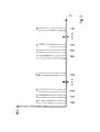
- the Fig. 1 shows by way of example a digital matrix code 1, which is composed of a plurality of markers 2, which are arranged distributed along rows (in the x-direction) and columns (along the y-direction), namely at regular intervals.
- a digital matrix code 1 which is composed of a plurality of markers 2, which are arranged distributed along rows (in the x-direction) and columns (along the y-direction), namely at regular intervals.
- the matrix arrangement of the marking points 2 completely covers the matrix code 1, although this need not be the case in practical application examples.
- the marks 2 according to the Fig. 1 arranged within a marker field 3.
- the individual marking points 2 can in principle be formed as in the DE 102 34 002 A1 and DE 101 22 335 C1 the applicant described, but with the modifications described below.
- a local deformation with a lens effect can be caused by the respective markings, so that the digital matrix code 1 can be read out automatically.
- This code so information, for example, in terms of material, nature, origin, date of production, etc. of the glass or in terms of content, origin, date of manufacture, lot number and the like in a product made of glass, for example, a primary packaging for the pharmaceutical industry, in particular a glass ampoule.
- a Data Matrix code according to ISO / IEC 16022: 2000 and ISO / IEC 24720: 2006 are used.
- the coding content may e.g. in accordance with the EFPIA (press release issued by the European Federation of Pharmaceutical Industries and Associations of 7 October 2008).
- a single focal length of a respective local deformation can be used, or different focal lengths of the same local deformation or the focal lengths of different local deformations can also be used. Furthermore, the distances between the individual deformations can be used to each other for coding information.
- the marking points 2 are now not formed with marking steps carried out immediately after one another, that is, row by row and column by column. Rather, the marking points 2 are set so that in a direction x, y directly adjacent markers are formed in two marking steps, which are not carried out directly successively, but between which a further marking step for forming a not immediately adjacent marking point 2 is executed.
- the immediately adjacent mark B11 will not be written after the mark A11 has been formed, but rather the mark A12 next to the mark in this example, and then the mark next to it A13, etc., until finally the entire first line of the matrix code 1 is written.
- the letter A marks written during the first scan of the respective matrix code line Accordingly, in the Fig. 1 Marks written in a subsequent scan of the same matrix code line, indicated by the letter B.
- the marker points B11, B12, B13, etc. are successively written until finally the entire first matrix code line is written with mark points then offset relative to the first scan. This process is repeated in accordance with the other matrix code lines, starting with A21, A31, etc., until finally all the matrix code 1 is written.
- the sequences formed by the marking points A11, A12, A13,... and by the marking points B11, B12, B13,... respectively form sequences of markings which are regularly spaced apart from one another and which are in the respectively predetermined direction (ie in the case of a line by line Scan in x-direction) are arranged nested.
- a writing laser beam is preferably used for writing the respective rows or columns.
- several mutually offset writing laser beams can be used simultaneously for this purpose.
- the markings are formed by means of short laser pulses, as exemplified in US Pat Fig. 2 shown.
- PA11, PA12, ... PAln Laser pulses designated for writing the marker points are used.
- Each laser pulse also heats a thin layer of glass.
- this heat zone or thermal action is low as possible.
- the shortest possible laser pulses are used. If two adjacent marking points were written directly one behind the other, this would result in a higher material temperature in the overlapping zone than in the case of individual laser pulses, which would have a negative effect on the strength.
- the temperature gradient is largely reduced by the preceding laser pulse and the temperature profile is similar to a laser bombardment without residual temperature from the formation of an immediately adjacent mark.
- the Fig. 3 shows by way of example an apparatus for carrying out the above method. It is assumed that the glass 5, for example, a glass tube, which is withdrawn from a glass tube manufacturing plant, is moved continuously or stepwise past a writing laser beam 9 of a writing laser 6, wherein the direction of movement is indicated by the arrow shown on the left edge.
- the writing laser beam 9 is suitably deflected by a scanner mirror 7 adjusted by a drive 8 in order to realize a relative movement between the writing laser beam 9 and the glass 5.
- the writing laser beam 9 can be scanned transversely across the tube circumference.
- the writing laser can be a pulsed CO 2 laser, with pulse rise times of less than 75 ⁇ sec, pulse frequencies of above 5 kHz and laser powers of less than 20W, the above parameters being intended to be exemplary only.
- the laser power for optimal formation of the marking points is predetermined, it has proven to be advantageous, the entire marking field 3 (see. Fig. 1 ) to preheat to a predetermined temperature.
- its immediate surroundings can also be preheated.
- a further heating laser 10 is used, which is suitably widened by means of a telescope or a beam widening 11 and suitably imaged onto the glass 5 as a widened heating laser beam 12.
- a heating laser 10 in particular a CO 2 laser can be used.
- Alternative sources of heat may also be a burner or an infrared heater.
- the marking field or marking field and its immediate surroundings can be heated to a predetermined temperature of at least 20K above the transformation temperature Tg of the glass.
- the additional heating power may also be such that the temperature of the marking field or the marking field and its immediate surroundings is heated to a temperature below a first predetermined temperature, which is at least 20K above the transformation temperature of the glass and the individual laser pulses can then be used to transfer the respective interaction zone of the writing laser beam with the glass to a suitable process temperature of at least 20K above the transformation temperature of the glass.
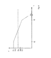
- the Fig. 4 shows the process temperatures in a method according to the present invention.
- the temperature T of an interaction zone that is to say either a single marking point or the entire marking field, is plotted against the time t.
- Tg denotes the transformation temperature of the glass, which is typically in the range of 500 ° C to 600 ° C.
- the actual writing process begins at time zero at a temperature T1, which according to the present invention is at least 20K above the transformation temperature Tg of the glass.
- the laser pulse used for writing has a time that is less than or equal to t1.
- the temperature of the interaction zone falls in a controlled manner from a value T1 to a value T2 which is at least 20K and more preferably at least 40K below the transformation temperature Tg of the glass. It must be ensured that all laser pulses in this temperature range and in the time T1 act on the glass.
- the temperature T2 is reached at the time t2, according to the Fig. 4 a linear temperature ramp is driven, although basically any other temperature curves are possible as long as the maximum process temperature T1 is not exceeded again during the controlled cooling.
- this further cooling process can also be started only after falling below a temperature of at least 50K below the transformation temperature of the glass.
- the heating laser beam 12 itself by reducing its power immediately following the formation of the check box.
- the marking field 3 can also be introduced immediately after the marking step into a downstream cooling region 13 and optionally pass through it until the temperature T2 has been reached.
- This downstream cooling area 13 can also be realized, for example, by a conventional infrared oven, which should preferably be in direct spatial proximity to the interaction area between the writing laser beam 9 and the glass 5.
- the preheating temperature can therefore also be below the transformation temperature Tg, although a preheating temperature TH1 is slightly below or identical to the first predetermined temperature T1.
- the Fig. 5a and 5b show in a comparison two formed on a glass tube matrix code marks that were generated at different powers of the writing laser beam. While in the matrix code according to the Fig. 5a the individual marker points are for the most part clearly separated from each other, these are used in the matrix code according to the Fig. 5b sometimes even into each other, which, however, surprisingly has no influence on the readability of the matrix code by means of an optical read-out device.
- a matrix code according to the Fig. 5b is generated, in particular, when laser spots that overlap slightly are used to write adjacent marker points. It has been found that such a small overlap can improve the readability of matrix codes. The optimum degree of overlap depends on the reading device used (lighting / optics). That is, the laser parameters can be optimized for a particular reading unit.
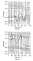
- Fig. 6a For example, the voltage across a marker point along a first direction and the Fig. 6b the corresponding voltage curve in a direction perpendicular to it (shown here is the so-called Friedel degree).
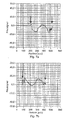
- the vertical arrows mark the beginning of the tube wall of the glass tube, where the measurement of the respective voltage curve due to the measuring method used are no longer meaningful. From these marker arrows Therefore, the respective measurement curve was set to the value zero. This also applies to the other curves in the FIGS. 7a to 8b ,
- an additional heating in the form of an additional heating laser beam as exemplified in the Fig. 3 shown, namely an expanded laser beam of another CO 2 laser.
- the power of the CO 2 laser was adjusted so that the marking field to be described and its immediate vicinity was already preheated to the aforementioned first predetermined temperature or to a value just below this temperature, wherein the first predetermined temperature is at least 20K above the temperature Transformation temperature of the glass is.
- a commercial continuous 100 W CO 2 laser company Synrad was used, the laser optics chosen and a telescope was adjusted so far that the entire marking field before writing to the writing laser beam to at least 20K above Tg could be heated up.
- a relatively short preheating time of, for example, a maximum of 6 seconds could be realized, so that the cycle times for writing matrix codes could be significantly reduced.
- the energy input was then approximately 25 W mm -2 s -1, for example, for a matrix code measuring 2 ⁇ 2 mm.
- a matrix code according to the invention can no longer be changed or manipulated in a finished product, for example a pharmaceutical product filled in a glass primary packaging medium.
- the matrix code proposed according to the invention can no longer be changed or falsified on the finished product, since the temperature treatment necessary for this can not be realized.
- the matrix code according to the present invention is thus safe from subsequent manipulation.
- the matrix code in the process of processing can be made unreadable or invalidated by heat treatment.
- This has the advantage, for example, that defective products identified in the processing process can be reliably identified by destroying the matrix code, and thus delivery to customers can be avoided.
- an additional test device 14 for example in the form of an optical detector, provided to check or detect properties of the glass. If an error is detected, the central controller 15 issues a control command which causes the glass product 5 to reenter the effective area of the writing laser beam 9 (or alternatively into the area of action of another writing laser beam downstream) to render the previously generated matrix code unrecognizable do.
- the product to be marked should be a glass tube withdrawn from a glass tube manufacturing facility
- a preferred application of the present invention concerns the marking of individual ones
- Primary packaging means made of glass or a vitreous material, for example of primary packaging materials for pharmaceutical or medical preparations, such as syringes, cartridges or vials, which can be marked and marked reliably and counterfeit-proof with the inventive method. If, for some reason, it should turn out that the primary packaging should not be used, the corresponding marking field can also be made unrecognizable or not readable by means of the device described above.
Landscapes
- Physics & Mathematics (AREA)
- Engineering & Computer Science (AREA)
- Optics & Photonics (AREA)
- Chemical & Material Sciences (AREA)
- Materials Engineering (AREA)
- Organic Chemistry (AREA)
- Toxicology (AREA)
- Chemical Kinetics & Catalysis (AREA)
- General Chemical & Material Sciences (AREA)
- Geochemistry & Mineralogy (AREA)
- Health & Medical Sciences (AREA)
- Life Sciences & Earth Sciences (AREA)
- General Physics & Mathematics (AREA)
- Theoretical Computer Science (AREA)
- Ceramic Engineering (AREA)
- Laser Beam Processing (AREA)
- Thermal Transfer Or Thermal Recording In General (AREA)
- Re-Forming, After-Treatment, Cutting And Transporting Of Glass Products (AREA)
- Details Of Rigid Or Semi-Rigid Containers (AREA)
- Surface Treatment Of Glass (AREA)
Claims (15)
- Un procédé de marquage de verre ou de matériau de type verre, dans lequel un rayon laser de marquage (9) et le verre ou le matériau de type verre (5) sont déplacement relativement l'une par rapport à l'autre pour la formation d'une zone de marques (3) dans ou sur le verre ou le matériau de type verre, consistant en une pluralité de marques discrètes (A, B) formées à la suite d'étapes de marquage discrètes et distribuée le long d'au moins une direction (x, y), dans lequel
les marques (A11, B11 ; A11, A21), qui sont directement adjacentes les unes aux autres suivant une direction prédéterminée (x, y) sont formées en deux étapes de marquage (PA11, PA12 ; PA11, PA31) qui ne sont pas exécutées directement en séquence l'une à la suite de l'autre et
les étapes de marquage forment au moins deux séries de marques suivant la direction prédéterminée (x ; y), espacées l'une de l'autre d'intervalles régulier et entrelacées suivant la direction prédéterminée,
caractérisée en ce que les séries respectives de marques régulièrement espacées sont formées par un mouvement relatif suivant une colonne ou une rangée entre le rayon laser de marquage (9) et le verre ou le matériau de type verre (5) le long de la direction prédéterminée (x ; y) ou par la formation de marques suivant une séquence aléatoire de telle manière que la formation de marques directement adjacentes par les étapes de marquage, qui sont effectuées directement en séquence l'une à la suite de l'autre, puisse être évitées. - Le procédé de la revendication 1, dans lequel une étape supplémentaire de marquage (PA12 ; PA31) pour la formation d'une marque supplémentaire (A12 ; A31) non directement adjacente à la première marque (PA11) suivant la direction prédéterminée, est effectuée entre une première étape de marquage respective (PA11) et une seconde étape de marquage respective (PB11 ; PA21) pour la formation respectivement d'une première et d'une seconde marques (A11, B11 ; A11, A21), qui sont disposés directement adjacentes l'une à l'autre suivant la direction prédéterminée.
- Le procédé selon l'une quelconque des revendications précédentes, dans lequel les marques sont formées au moyens de brefs pulses laser, dans lequel les marques de la zone de marques (3) forment une matrice bi-dimensionnelle (1), dans laquelle les marques sont disposées le long de deux directions mutuellement orthogonales (x, y) et à distance l'une de l'autre, pour l'encodage d'une information, dans lequel la zone de marques (3) ou la zone de marques (3) avec son voisinage immédiat est chauffé à une température prédéterminée, en particulier au moyen d'une radiation optique et de préférence au moyen d'un rayon laser chauffant à expansion (12).
- Le procédé selon la revendication 3, dans lequel la puissance des pulses laser est telle que les marques sont formées à une première température déterminée (T1) égale à au moins 20K au-dessus de la température de transformation (Tg) du verre et dans lequel la zone de marques (3) ou la zone de marques (3) avec son voisinage immédiat est chauffée à une température (TH1 ; TH2) inférieure à la première température déterminée (T1).
- Le procédé selon la revendication 3 ou 4, dans lequel les marques ou la zone de marques (3) est/sont refroidie(s) d'une manière contrôlée durant et/ou à la suite de l'exécution des étapes de marquage jusqu'à l'obtention d'une seconde température prédéterminée (T2) inférieure à la température de transformation (Tg) du verre, dans lequel la seconde température prédéterminée (T2) est au moins 20K et de préférence au moins 40 K sous la température de transformation du verre et/ou une étape supplémentaire de refroidissement est effectuée, lorsque la température chute en dessous de la seconde température prédéterminée, et plus préférentiellement lorsque la température chute en deçà d'une température égale à au moins 50K sous la température de transformation du verre.
- Le procédé selon l'une quelconque des revendication précédentes, dans lequel au moins une durée d'au moins 0.01 seconde existe entre deux étapes de marquage (PA11, PB11 ; PA11, PA21) pour la génération de marques directement adjacentes (A11, B11 ; A11, A21), dans lequel l'intensité au sein du verre du rayon laser de marquage (9) est réduite voire supprimée.
- Le procédé selon l'une quelconque des revendications précédentes, dans lequel au moins certaines desdites marques discrètes (A, B), qui sont directement adjacentes les unes par rapport aux autres au sein de la zone de marques (3), se superposent partiellement les unes par rapport aux autres.
- Le procédé selon la revendication 7, dans lequel ces marques discrètes (A, B), qui sont directement adjacentes les unes par rapport aux autres au sein de la zone de marques (3), sont formées en marques circulaires, chacune ayant un diamètre prédéterminé tel que le diamètre prédéterminé respective desdites marques directement adjacentes est plus important d'au moins 10%, et de préférence jusqu'à 20% que la distance entre ces marques.
- Le procédé selon l'une quelconque des revendications précédentes, dans lequel le verre ou un produit en verre formé par ce procédé est testé jusqu'à un état de chauffage, et les marques de la zone de marques d'un verre défectueux ou d'un produit en verre sont rendues illisibles ou invalides par traitement thermique.
- Un dispositif de marquage de verre ou de matériau de type verre au moyen d'une pluralité de marques discrètes dans ou sur le verre ou le matériau de type verre (5), formant ensemble une zone de marques (3), notamment pour effectuer le procédé selon l'une quelconque des revendications précédentes, ledit appareil comprenant :un laser de marquage (6) pour la génération d'un rayon laser de marquage (9) imagée sur le verre ou le matériau etdes moyens d'ajustement pour le déplacement du rayon laser de marquage (9) et le verre ou le matériau (5) relativement l'un à l'autre durant la formation de la zone de marques (3), dans lequelles moyens d'ajustement sont configurés pour le déplacement du rayons laser de marquage et le verre ou le matériau, relativement l'un à l'autre, de telle manière qu'une pluralité de marques discrètes est formée au sein ou sur le verre ou le matériau, formant ensemble la zone de marques (3), etdes moyens de commande sont mis à disposition (15), configurés pour que les marques (A11, B11 ; A11, A21), qui sont directement adjacentes les unes par rapport aux autres suivant une direction prédéterminée (x, y), sont formées suivant deux étapes de marquage (PA11, PA12; PA11, PA31) qui ne sont pas effectivement directement l'une après l'autre,caractérisé en ce que les moyens de commande (15) sont configurés en outre de manière que les séries respectives de marques régulièrement espacées sont formées par un mouvement relatif suivant une colonne ou une rangée entre le rayon laser de marquage (9) et le verre ou le matériau de type verre (5) le long de la direction prédéterminée (x ; y) ou par la formation de marques suivant une séquence aléatoire de telle manière que la formation de marques directement adjacentes par les étapes de marquage, qui sont effectuées directement en séquence l'une à la suite de l'autre, puisse être évitées.
- Le dispositif selon la revendication 10, dans lequel lesdits moyens de commande (15) sont configuré en outre de manière à ce qu'une étape supplémentaire de marquage (PA12 ; PA31) pour la formation d'une marque supplémentaire (A12 ; A31) non directement adjacente à la première marque (PA11) suivant la direction prédéterminée, est effectuée entre une première étape de marquage respective (PA11) et une seconde étape de marquage respective (PB11 ; PA21) pour la formation respectivement d'une première et d'une seconde marques (A11, B11 ; A11, A21), qui sont disposés directement adjacentes l'une à l'autre suivant la direction prédéterminée.
- Le dispositif selon la revendication 10 ou 11, dans lequel le laser de marquage (6) forme les marques au moyens de brefs pulses laser, dans lequel les moyens de commande (15) sont configurés en outre pour que les marques de la zone de marques (3) forment une matrice bi-dimensionnelle (1), dans laquelle les marques sont disposées le long de deux directions mutuellement orthogonales (x, y) et à distance l'une de l'autre, et décalées l'une par rapport à l'autre pour l'encodage d'une information.
- Le dispositif selon la revendication 12, dans lequel un dispositif de chauffage chauffe la zone de marques (3) ou la zone de marques avec son voisinage immédiat à une température prédéterminée.
- Le dispositif selon l'une quelconque des revendications 10 à 13, dans lequel lesdits moyens de commande (15) sont configurés de telle manière que les marques discrètes (A, B), qui sont directement adjacentes les unes par rapport aux autres au sein de la zone de marques (3), sont formées en marques circulaires, chacune ayant un diamètre prédéterminé tel que le diamètre prédéterminé respective desdites marques directement adjacentes est plus important d'au moins 10%, et de préférence jusqu'à 20% que la distance entre ces marques.
- Le dispositif selon l'une quelconque des revendications 10 à 14, comprenant en outre des moyens de test et de traitement pour la vérification du verre ou d'un produit en verre en résultant jusqu'à un état de chauffage pour rendre grâce à un traitement thermique illisibles ou invalides les marques sur la zone de marques d'un verre ou d'un produit en verre défectueux .
Applications Claiming Priority (2)
| Application Number | Priority Date | Filing Date | Title |
|---|---|---|---|
| DE102010037273A DE102010037273A1 (de) | 2010-09-02 | 2010-09-02 | Verfahren und Vorrichtung zum Markieren von Glas |
| PCT/EP2011/064901 WO2012028611A1 (fr) | 2010-09-02 | 2011-08-30 | Procédé et dispositif de marquage de verre |
Publications (2)
| Publication Number | Publication Date |
|---|---|
| EP2577553A1 EP2577553A1 (fr) | 2013-04-10 |
| EP2577553B1 true EP2577553B1 (fr) | 2014-10-01 |
Family
ID=44587815
Family Applications (1)
| Application Number | Title | Priority Date | Filing Date |
|---|---|---|---|
| EP11754859.4A Active EP2577553B1 (fr) | 2010-09-02 | 2011-08-30 | Procédé et dispositif de marquage de verre |
Country Status (6)
| Country | Link |
|---|---|
| US (1) | US8872870B2 (fr) |
| EP (1) | EP2577553B1 (fr) |
| JP (1) | JP5442168B2 (fr) |
| CN (1) | CN103080948B (fr) |
| DE (1) | DE102010037273A1 (fr) |
| WO (1) | WO2012028611A1 (fr) |
Families Citing this family (21)
| Publication number | Priority date | Publication date | Assignee | Title |
|---|---|---|---|---|
| PL2973235T3 (pl) * | 2013-03-15 | 2021-11-22 | Crown Packaging Technology, Inc. | Kody kreskowe matrycowe na elementach składowych puszki |
| CN103659004B (zh) * | 2013-12-12 | 2016-08-24 | 大族激光科技产业集团股份有限公司 | 激光切割预处理装置、激光切割装置及激光切割方法 |
| FR3017483B1 (fr) * | 2014-02-11 | 2018-05-18 | Saint-Gobain Glass France | Feuille de verre avec code d'identification |
| DE102014210611A1 (de) * | 2014-06-04 | 2015-12-17 | Trumpf Werkzeugmaschinen Gmbh + Co. Kg | Verfahren zum Markieren eines DataMatrix-Codes auf einem Werkstück mittels eines Laserstrahls |
| EP3047932B1 (fr) * | 2015-01-21 | 2018-12-26 | Agie Charmilles New Technologies SA | Procédé d'ablation par laser en vu de graver une surface avec optimisation de zone de traitement, avec programme et machine correspondants |
| WO2017210315A1 (fr) | 2016-05-31 | 2017-12-07 | Corning Incorporated | Mesures anti-contrefaçon pour articles en verre |
| EP3529223A1 (fr) * | 2016-10-20 | 2019-08-28 | Corning Incorporated | Bosses de verre à dépressions sur des articles en verre et leurs procédés de formation |
| CN106645778B (zh) * | 2016-11-17 | 2023-05-30 | 天津滨海光热反射技术有限公司 | 超薄玻璃编码方法 |
| CN106739539A (zh) * | 2016-11-28 | 2017-05-31 | 广西大学 | 一种零件打标机编号方法及其装置 |
| DE102017102161A1 (de) | 2016-12-30 | 2018-07-05 | Schott Ag | Verfahren zum Weiterverarbeiten eines Glasrohr-Halbzeugs |
| CN108178496A (zh) * | 2016-12-08 | 2018-06-19 | 肖特股份有限公司 | 用于再加工玻璃管半成品的方法 |
| DE102016123865A1 (de) * | 2016-12-08 | 2018-06-14 | Schott Ag | Verfahren zum Weiterverarbeiten eines Glasrohr-Halbzeugs einschließlich einer thermischen Umformung |
| DE102016124833A1 (de) | 2016-12-19 | 2018-06-21 | Schott Ag | Verfahren zum Herstellen eines Hohlglasprodukts aus einem Glasrohr-Halbzeug mit Markierungen, sowie Verwendungen hiervon |
| DE102016125129A1 (de) | 2016-12-21 | 2018-06-21 | Schott Ag | Verfahren zum Herstellen eines Glasrohr-Halbzeugs oder eines daraus hergestellten Hohlglasprodukts mit Markierungen, sowie Verwendungen hiervon |
| KR102409423B1 (ko) * | 2017-09-22 | 2022-06-16 | 주식회사 엘지에너지솔루션 | 레이저 송출 특성 값 결정방법 |
| WO2019113029A1 (fr) | 2017-12-04 | 2019-06-13 | Corning Incorporated | Vitrocéramiques et articles vitrocéramiques ayant des caractéristiques de blocage des uv et nir |
| US20190275616A1 (en) * | 2018-03-06 | 2019-09-12 | Goodrich Corporation | Method for improving visual contrast of laser etch marking on painted substrates |
| US11738409B2 (en) * | 2018-05-25 | 2023-08-29 | Laserax Inc. | Metal workpieces with shot blast resistant identifiers, methods and systems for laser-marking such identifiers |
| FR3087367B1 (fr) * | 2018-10-22 | 2020-11-06 | Tiama | Procede et installation pour le marquage de recipients chauds en verre |
| BR112021023592A2 (pt) | 2019-06-28 | 2022-01-04 | Becton Dickinson France | Flange de plástico para recipiente médico, recipiente médico incluindo este flange de plástico e um método para fabricar este recipiente médico |
| WO2020260298A1 (fr) | 2019-06-28 | 2020-12-30 | Becton Dickinson France | Adaptateur pour récipient médical, récipient médical comprenant ledit adaptateur, et procédé de fabrication de ce récipient médical |
Family Cites Families (20)
| Publication number | Priority date | Publication date | Assignee | Title |
|---|---|---|---|---|
| CS214081B1 (en) | 1980-06-26 | 1982-04-09 | Peter Urbanek | Method of glass products surface treatment by means of infrared radiation of laser and apparatus for making the same |
| DE4126626C2 (de) | 1990-08-15 | 1994-08-04 | United Distillers Plc | Markierter Materialkörper und Verfahren zu dessen Herstellung |
| US5229574A (en) * | 1991-10-15 | 1993-07-20 | Videojet Systems International, Inc. | Print quality laser marker apparatus |
| DE4224282A1 (de) | 1992-07-23 | 1994-01-27 | Kristina Dipl Ing Schmidt | Verfahren zur abtragenden Mikrostrukturierung von Glas |
| CA2152067A1 (fr) | 1992-12-18 | 1994-07-07 | Boris Goldfarb | Methode et appareil de gravure d'images dans des corps solides |
| GB2281129B (en) | 1993-08-19 | 1997-04-09 | United Distillers Plc | Method of marking a body of glass |
| DE4407547C2 (de) | 1994-03-07 | 1996-05-30 | Swarovski & Co | Körper aus transparentem Material mit einer Markierung und Verfahren zu dessen Herstellung |
| SE503496C2 (sv) | 1994-10-04 | 1996-06-24 | Permanova Lasersystem Ab | Metod och anordning för att utföra flera identiska graveringar med hjälp av en laserstråle |
| US5801356A (en) | 1995-08-16 | 1998-09-01 | Santa Barbara Research Center | Laser scribing on glass using Nd:YAG laser |
| DE19926878A1 (de) | 1998-06-12 | 1999-12-16 | Matias Risse | Unverfälschbares Gravierungsverfahren zur Verwendung auf Glasbehältern |
| DE19855623C1 (de) | 1998-12-02 | 2000-02-24 | Lpkf Laser & Electronics Ag | Verfahren zur Erzeugung einer Markierung in einem Glaskörper |
| IL127388A0 (en) | 1998-12-03 | 1999-10-28 | Universal Crystal Ltd | Material processing applications of lasers using optical breakdown |
| DE10122335C1 (de) | 2001-05-08 | 2002-07-25 | Schott Glas | Verfahren und Vorrichtung zum Markieren von Glas mit einem Laser |
| US7675001B2 (en) | 2002-06-19 | 2010-03-09 | Frewitt Printing Sa | Method and a device for depositing a wipe-proof and rub-proof marking onto transparent glass |
| DE10234002B4 (de) | 2002-07-25 | 2006-07-20 | Schott Ag | Verfahren zum Markieren von Glas |
| FR2885248B1 (fr) | 2005-04-28 | 2007-08-10 | Becton Dickinson France Soc Pa | Procede d'identification d'une multiplicite de contenants et/ou d'articles finis obtenus a partir desdits contenants |
| FR2885071B1 (fr) | 2005-04-28 | 2010-02-12 | Becton Dickinson France | Procede d'identification d'un contenant et/ou d'un article fini obtenu a partir dudit contenant, en particulier a usage medical |
| US7898524B2 (en) * | 2005-06-30 | 2011-03-01 | Logitech Europe S.A. | Optical displacement detection over varied surfaces |
| US8173038B2 (en) * | 2008-04-18 | 2012-05-08 | Corning Incorporated | Methods and systems for forming microstructures in glass substrates |
| US20100119808A1 (en) * | 2008-11-10 | 2010-05-13 | Xinghua Li | Method of making subsurface marks in glass |
-
2010
- 2010-09-02 DE DE102010037273A patent/DE102010037273A1/de not_active Ceased
-
2011
- 2011-08-30 CN CN201180041145.0A patent/CN103080948B/zh active Active
- 2011-08-30 WO PCT/EP2011/064901 patent/WO2012028611A1/fr active Application Filing
- 2011-08-30 EP EP11754859.4A patent/EP2577553B1/fr active Active
- 2011-08-30 JP JP2013526443A patent/JP5442168B2/ja active Active
- 2011-08-30 US US13/811,315 patent/US8872870B2/en active Active
Also Published As
| Publication number | Publication date |
|---|---|
| JP5442168B2 (ja) | 2014-03-12 |
| CN103080948B (zh) | 2016-03-23 |
| JP2013543164A (ja) | 2013-11-28 |
| CN103080948A (zh) | 2013-05-01 |
| US20130169732A1 (en) | 2013-07-04 |
| EP2577553A1 (fr) | 2013-04-10 |
| DE102010037273A1 (de) | 2012-03-08 |
| WO2012028611A1 (fr) | 2012-03-08 |
| US8872870B2 (en) | 2014-10-28 |
Similar Documents
| Publication | Publication Date | Title |
|---|---|---|
| EP2577553B1 (fr) | Procédé et dispositif de marquage de verre | |
| EP3333135B1 (fr) | Procédé de traitement ultérieur d'un demi-produit sous la forme de tube de verre, notamment un formage thermique | |
| EP2144728B1 (fr) | Procédé pour mettre en place une structure dans une surface d'une pièce à usiner transparente | |
| EP3300885A1 (fr) | Procédé d'étalonnage d'un dispositif de fabrication d'un objet tridimensionnel et dispositif réalisé pour la mise en oeuvre du procédé | |
| DE102018126381A1 (de) | Verfahren und Vorrichtung zum Einfügen einer Trennlinie in ein transparentes sprödbrüchiges Material, sowie verfahrensgemäß herstellbares, mit einer Trennlinie versehenes Element | |
| DE3829025A1 (de) | Verfahren zum aufbringen und lesen von und flasche mit optisch lesbaren codemarkierungen | |
| EP3544761A1 (fr) | Dispositif d'exposition aux rayonnements et machine d'usinage pourvue d'un tel dispositif d'exposition aux rayonnements | |
| EP3336066A2 (fr) | Procédé de fabrication d'un produit en verre creux à partir d'un demi-produit sous la forme de tube de verre pourvu de marquages ainsi que ses utilisations | |
| EP2191976B1 (fr) | Procédé de marquage ou d'inscription d'une pièce à usiner | |
| DE102018200029A1 (de) | Verfahren und Laserbearbeitungsmaschine zur Oberflächenstrukturierung lasertransparenter Werkstücke | |
| EP3339259A1 (fr) | Procédé de fabrication d'un demi-produit sous la forme d'un tube de verre ou d'un produit en verre creux fabriqué à partir dudit demi-produit sous la forme d'un tube de verre ainsi que ses utilisations | |
| DE10234002B4 (de) | Verfahren zum Markieren von Glas | |
| DE69838083T2 (de) | Verfahren zum markieren eines objekts aus durchsichtigem synthetischem material,insbesondere einer opthalmischen linse, markiertes objekt und methode zur identifikation eines solchen objekts | |
| EP3015279A1 (fr) | Procédé de fabrication d'un élément de sécurité comprenant une image lenticulaire | |
| EP0644162B1 (fr) | Procédé de commande de la déformation libre d'une matière thermoplastique | |
| DE69607336T2 (de) | Lasermarkierungsverfahren eines werkstückes aus glas,und dafür hergestelltes werkstück aus glas,insbesondere giessform einer ophtalmologischen linse | |
| DE102014215439B4 (de) | Verfahren zum Herstellen einer Struktur | |
| DE10162111A1 (de) | Verfahren und Vorrichtung zur Veränderung der komplexen Brechzahl mittels elektromagnetischer Strahlung im Inneren von für diese Strahlung durchlässigen Bauteilen | |
| EP1897699B1 (fr) | Procédé et dispositif destinés à la fabrication d'objets en polyéthylène dotés d'une marque d'informations codées lisibles par une machine | |
| DE102011075171A1 (de) | Preferential Heating mit Plasma | |
| DE2113720B2 (de) | Verfahren zur Durchmesserregelung beim tiegellosen Zonenschmelzen von Halbleiterstäben | |
| EP2157533A1 (fr) | Procédé d'identification de récipients médicaux | |
| DE102017207921A1 (de) | Verfahren zum Aufbringen einer Kennzeichnung auf ein Objekt, Vorrichtung zum Markieren von Objekten und Trägerkörper mit einer Mehrzahl von Kennzeichnungskörpern | |
| DE102018130639A1 (de) | Vorrichtung zum Erwärmen von Kunststoffvorformlingen mit Abschirmplatte für Wärmestrahlungen | |
| DE102007024546A1 (de) | Verfahren zum Kennzeichnen extrudierter Kunststoffprofile |
Legal Events
| Date | Code | Title | Description |
|---|---|---|---|
| PUAI | Public reference made under article 153(3) epc to a published international application that has entered the european phase |
Free format text: ORIGINAL CODE: 0009012 |
|
| 17P | Request for examination filed |
Effective date: 20130103 |
|
| AK | Designated contracting states |
Kind code of ref document: A1 Designated state(s): AL AT BE BG CH CY CZ DE DK EE ES FI FR GB GR HR HU IE IS IT LI LT LU LV MC MK MT NL NO PL PT RO RS SE SI SK SM TR |
|
| DAX | Request for extension of the european patent (deleted) | ||
| GRAP | Despatch of communication of intention to grant a patent |
Free format text: ORIGINAL CODE: EPIDOSNIGR1 |
|
| INTG | Intention to grant announced |
Effective date: 20140620 |
|
| GRAS | Grant fee paid |
Free format text: ORIGINAL CODE: EPIDOSNIGR3 |
|
| GRAA | (expected) grant |
Free format text: ORIGINAL CODE: 0009210 |
|
| AK | Designated contracting states |
Kind code of ref document: B1 Designated state(s): AL AT BE BG CH CY CZ DE DK EE ES FI FR GB GR HR HU IE IS IT LI LT LU LV MC MK MT NL NO PL PT RO RS SE SI SK SM TR |
|
| REG | Reference to a national code |
Ref country code: GB Ref legal event code: FG4D Free format text: NOT ENGLISH |
|
| REG | Reference to a national code |
Ref country code: AT Ref legal event code: REF Ref document number: 689842 Country of ref document: AT Kind code of ref document: T Effective date: 20141015 Ref country code: CH Ref legal event code: EP |
|
| REG | Reference to a national code |
Ref country code: IE Ref legal event code: FG4D Free format text: LANGUAGE OF EP DOCUMENT: GERMAN |
|
| REG | Reference to a national code |
Ref country code: DE Ref legal event code: R096 Ref document number: 502011004551 Country of ref document: DE Effective date: 20141113 |
|
| REG | Reference to a national code |
Ref country code: NL Ref legal event code: VDEP Effective date: 20141001 |
|
| REG | Reference to a national code |
Ref country code: LT Ref legal event code: MG4D |
|
| PG25 | Lapsed in a contracting state [announced via postgrant information from national office to epo] |
Ref country code: NL Free format text: LAPSE BECAUSE OF FAILURE TO SUBMIT A TRANSLATION OF THE DESCRIPTION OR TO PAY THE FEE WITHIN THE PRESCRIBED TIME-LIMIT Effective date: 20141001 |
|
| PG25 | Lapsed in a contracting state [announced via postgrant information from national office to epo] |
Ref country code: IS Free format text: LAPSE BECAUSE OF FAILURE TO SUBMIT A TRANSLATION OF THE DESCRIPTION OR TO PAY THE FEE WITHIN THE PRESCRIBED TIME-LIMIT Effective date: 20150201 Ref country code: NO Free format text: LAPSE BECAUSE OF FAILURE TO SUBMIT A TRANSLATION OF THE DESCRIPTION OR TO PAY THE FEE WITHIN THE PRESCRIBED TIME-LIMIT Effective date: 20150101 Ref country code: CZ Free format text: LAPSE BECAUSE OF FAILURE TO SUBMIT A TRANSLATION OF THE DESCRIPTION OR TO PAY THE FEE WITHIN THE PRESCRIBED TIME-LIMIT Effective date: 20141001 Ref country code: FI Free format text: LAPSE BECAUSE OF FAILURE TO SUBMIT A TRANSLATION OF THE DESCRIPTION OR TO PAY THE FEE WITHIN THE PRESCRIBED TIME-LIMIT Effective date: 20141001 Ref country code: ES Free format text: LAPSE BECAUSE OF FAILURE TO SUBMIT A TRANSLATION OF THE DESCRIPTION OR TO PAY THE FEE WITHIN THE PRESCRIBED TIME-LIMIT Effective date: 20141001 Ref country code: PT Free format text: LAPSE BECAUSE OF FAILURE TO SUBMIT A TRANSLATION OF THE DESCRIPTION OR TO PAY THE FEE WITHIN THE PRESCRIBED TIME-LIMIT Effective date: 20150202 Ref country code: LT Free format text: LAPSE BECAUSE OF FAILURE TO SUBMIT A TRANSLATION OF THE DESCRIPTION OR TO PAY THE FEE WITHIN THE PRESCRIBED TIME-LIMIT Effective date: 20141001 |
|
| PG25 | Lapsed in a contracting state [announced via postgrant information from national office to epo] |
Ref country code: PL Free format text: LAPSE BECAUSE OF FAILURE TO SUBMIT A TRANSLATION OF THE DESCRIPTION OR TO PAY THE FEE WITHIN THE PRESCRIBED TIME-LIMIT Effective date: 20141001 Ref country code: LV Free format text: LAPSE BECAUSE OF FAILURE TO SUBMIT A TRANSLATION OF THE DESCRIPTION OR TO PAY THE FEE WITHIN THE PRESCRIBED TIME-LIMIT Effective date: 20141001 Ref country code: HR Free format text: LAPSE BECAUSE OF FAILURE TO SUBMIT A TRANSLATION OF THE DESCRIPTION OR TO PAY THE FEE WITHIN THE PRESCRIBED TIME-LIMIT Effective date: 20141001 Ref country code: SE Free format text: LAPSE BECAUSE OF FAILURE TO SUBMIT A TRANSLATION OF THE DESCRIPTION OR TO PAY THE FEE WITHIN THE PRESCRIBED TIME-LIMIT Effective date: 20141001 Ref country code: GR Free format text: LAPSE BECAUSE OF FAILURE TO SUBMIT A TRANSLATION OF THE DESCRIPTION OR TO PAY THE FEE WITHIN THE PRESCRIBED TIME-LIMIT Effective date: 20150102 Ref country code: CY Free format text: LAPSE BECAUSE OF FAILURE TO SUBMIT A TRANSLATION OF THE DESCRIPTION OR TO PAY THE FEE WITHIN THE PRESCRIBED TIME-LIMIT Effective date: 20141001 Ref country code: RS Free format text: LAPSE BECAUSE OF FAILURE TO SUBMIT A TRANSLATION OF THE DESCRIPTION OR TO PAY THE FEE WITHIN THE PRESCRIBED TIME-LIMIT Effective date: 20141001 |
|
| REG | Reference to a national code |
Ref country code: DE Ref legal event code: R097 Ref document number: 502011004551 Country of ref document: DE |
|
| PG25 | Lapsed in a contracting state [announced via postgrant information from national office to epo] |
Ref country code: EE Free format text: LAPSE BECAUSE OF FAILURE TO SUBMIT A TRANSLATION OF THE DESCRIPTION OR TO PAY THE FEE WITHIN THE PRESCRIBED TIME-LIMIT Effective date: 20141001 Ref country code: SK Free format text: LAPSE BECAUSE OF FAILURE TO SUBMIT A TRANSLATION OF THE DESCRIPTION OR TO PAY THE FEE WITHIN THE PRESCRIBED TIME-LIMIT Effective date: 20141001 Ref country code: RO Free format text: LAPSE BECAUSE OF FAILURE TO SUBMIT A TRANSLATION OF THE DESCRIPTION OR TO PAY THE FEE WITHIN THE PRESCRIBED TIME-LIMIT Effective date: 20141001 Ref country code: DK Free format text: LAPSE BECAUSE OF FAILURE TO SUBMIT A TRANSLATION OF THE DESCRIPTION OR TO PAY THE FEE WITHIN THE PRESCRIBED TIME-LIMIT Effective date: 20141001 |
|
| PLBE | No opposition filed within time limit |
Free format text: ORIGINAL CODE: 0009261 |
|
| STAA | Information on the status of an ep patent application or granted ep patent |
Free format text: STATUS: NO OPPOSITION FILED WITHIN TIME LIMIT |
|
| REG | Reference to a national code |
Ref country code: FR Ref legal event code: PLFP Year of fee payment: 5 |
|
| 26N | No opposition filed |
Effective date: 20150702 |
|
| PG25 | Lapsed in a contracting state [announced via postgrant information from national office to epo] |
Ref country code: SI Free format text: LAPSE BECAUSE OF FAILURE TO SUBMIT A TRANSLATION OF THE DESCRIPTION OR TO PAY THE FEE WITHIN THE PRESCRIBED TIME-LIMIT Effective date: 20141001 |
|
| PG25 | Lapsed in a contracting state [announced via postgrant information from national office to epo] |
Ref country code: MC Free format text: LAPSE BECAUSE OF FAILURE TO SUBMIT A TRANSLATION OF THE DESCRIPTION OR TO PAY THE FEE WITHIN THE PRESCRIBED TIME-LIMIT Effective date: 20141001 Ref country code: LU Free format text: LAPSE BECAUSE OF FAILURE TO SUBMIT A TRANSLATION OF THE DESCRIPTION OR TO PAY THE FEE WITHIN THE PRESCRIBED TIME-LIMIT Effective date: 20150830 |
|
| REG | Reference to a national code |
Ref country code: IE Ref legal event code: MM4A |
|
| PG25 | Lapsed in a contracting state [announced via postgrant information from national office to epo] |
Ref country code: IE Free format text: LAPSE BECAUSE OF NON-PAYMENT OF DUE FEES Effective date: 20150830 |
|
| REG | Reference to a national code |
Ref country code: FR Ref legal event code: PLFP Year of fee payment: 6 |
|
| PG25 | Lapsed in a contracting state [announced via postgrant information from national office to epo] |
Ref country code: MT Free format text: LAPSE BECAUSE OF FAILURE TO SUBMIT A TRANSLATION OF THE DESCRIPTION OR TO PAY THE FEE WITHIN THE PRESCRIBED TIME-LIMIT Effective date: 20141001 |
|
| PG25 | Lapsed in a contracting state [announced via postgrant information from national office to epo] |
Ref country code: BG Free format text: LAPSE BECAUSE OF FAILURE TO SUBMIT A TRANSLATION OF THE DESCRIPTION OR TO PAY THE FEE WITHIN THE PRESCRIBED TIME-LIMIT Effective date: 20141001 Ref country code: SM Free format text: LAPSE BECAUSE OF FAILURE TO SUBMIT A TRANSLATION OF THE DESCRIPTION OR TO PAY THE FEE WITHIN THE PRESCRIBED TIME-LIMIT Effective date: 20141001 Ref country code: HU Free format text: LAPSE BECAUSE OF FAILURE TO SUBMIT A TRANSLATION OF THE DESCRIPTION OR TO PAY THE FEE WITHIN THE PRESCRIBED TIME-LIMIT; INVALID AB INITIO Effective date: 20110830 |
|
| PG25 | Lapsed in a contracting state [announced via postgrant information from national office to epo] |
Ref country code: BE Free format text: LAPSE BECAUSE OF NON-PAYMENT OF DUE FEES Effective date: 20150831 |
|
| REG | Reference to a national code |
Ref country code: FR Ref legal event code: PLFP Year of fee payment: 7 |
|
| PG25 | Lapsed in a contracting state [announced via postgrant information from national office to epo] |
Ref country code: TR Free format text: LAPSE BECAUSE OF FAILURE TO SUBMIT A TRANSLATION OF THE DESCRIPTION OR TO PAY THE FEE WITHIN THE PRESCRIBED TIME-LIMIT Effective date: 20141001 |
|
| REG | Reference to a national code |
Ref country code: AT Ref legal event code: MM01 Ref document number: 689842 Country of ref document: AT Kind code of ref document: T Effective date: 20160830 |
|
| PG25 | Lapsed in a contracting state [announced via postgrant information from national office to epo] |
Ref country code: AT Free format text: LAPSE BECAUSE OF NON-PAYMENT OF DUE FEES Effective date: 20160830 |
|
| PG25 | Lapsed in a contracting state [announced via postgrant information from national office to epo] |
Ref country code: MK Free format text: LAPSE BECAUSE OF FAILURE TO SUBMIT A TRANSLATION OF THE DESCRIPTION OR TO PAY THE FEE WITHIN THE PRESCRIBED TIME-LIMIT Effective date: 20141001 |
|
| REG | Reference to a national code |
Ref country code: FR Ref legal event code: PLFP Year of fee payment: 8 |
|
| PG25 | Lapsed in a contracting state [announced via postgrant information from national office to epo] |
Ref country code: AL Free format text: LAPSE BECAUSE OF FAILURE TO SUBMIT A TRANSLATION OF THE DESCRIPTION OR TO PAY THE FEE WITHIN THE PRESCRIBED TIME-LIMIT Effective date: 20141001 |
|
| REG | Reference to a national code |
Ref country code: GB Ref legal event code: 732E Free format text: REGISTERED BETWEEN 20221117 AND 20221123 |
|
| REG | Reference to a national code |
Ref country code: DE Ref legal event code: R081 Ref document number: 502011004551 Country of ref document: DE Owner name: SCHOTT PHARMA AG & CO. KGAA, DE Free format text: FORMER OWNER: SCHOTT AG, 55122 MAINZ, DE Ref country code: DE Ref legal event code: R081 Ref document number: 502011004551 Country of ref document: DE Owner name: SCHOTT AG, DE Free format text: FORMER OWNER: SCHOTT AG, 55122 MAINZ, DE Ref country code: DE Ref legal event code: R082 Ref document number: 502011004551 Country of ref document: DE |
|
| P01 | Opt-out of the competence of the unified patent court (upc) registered |
Effective date: 20230516 |
|
| REG | Reference to a national code |
Ref country code: GB Ref legal event code: 732E Free format text: REGISTERED BETWEEN 20230914 AND 20230920 |
|
| PGFP | Annual fee paid to national office [announced via postgrant information from national office to epo] |
Ref country code: IT Payment date: 20230825 Year of fee payment: 13 Ref country code: GB Payment date: 20230822 Year of fee payment: 13 Ref country code: CH Payment date: 20230902 Year of fee payment: 13 |
|
| PGFP | Annual fee paid to national office [announced via postgrant information from national office to epo] |
Ref country code: FR Payment date: 20230824 Year of fee payment: 13 Ref country code: DE Payment date: 20230821 Year of fee payment: 13 |