EP2144728B1 - Procédé pour mettre en place une structure dans une surface d'une pièce à usiner transparente - Google Patents
Procédé pour mettre en place une structure dans une surface d'une pièce à usiner transparente Download PDFInfo
- Publication number
- EP2144728B1 EP2144728B1 EP08735149.0A EP08735149A EP2144728B1 EP 2144728 B1 EP2144728 B1 EP 2144728B1 EP 08735149 A EP08735149 A EP 08735149A EP 2144728 B1 EP2144728 B1 EP 2144728B1
- Authority
- EP
- European Patent Office
- Prior art keywords
- laser beam
- workpiece
- laser
- focus
- target
- Prior art date
- Legal status (The legal status is an assumption and is not a legal conclusion. Google has not performed a legal analysis and makes no representation as to the accuracy of the status listed.)
- Not-in-force
Links
- 238000000034 method Methods 0.000 title claims description 50
- 239000013077 target material Substances 0.000 claims description 27
- 239000011521 glass Substances 0.000 claims description 19
- 239000000463 material Substances 0.000 claims description 19
- 239000002245 particle Substances 0.000 claims description 15
- 229910052751 metal Inorganic materials 0.000 claims description 10
- 239000002184 metal Substances 0.000 claims description 10
- 230000008569 process Effects 0.000 claims description 8
- 229910000831 Steel Inorganic materials 0.000 claims description 7
- 239000010959 steel Substances 0.000 claims description 7
- 230000008018 melting Effects 0.000 claims description 3
- 238000002844 melting Methods 0.000 claims description 3
- 239000000758 substrate Substances 0.000 description 16
- 239000012780 transparent material Substances 0.000 description 13
- 239000011888 foil Substances 0.000 description 8
- 238000010330 laser marking Methods 0.000 description 7
- 238000002474 experimental method Methods 0.000 description 6
- 230000035515 penetration Effects 0.000 description 6
- 238000009792 diffusion process Methods 0.000 description 5
- 229910052782 aluminium Inorganic materials 0.000 description 4
- XAGFODPZIPBFFR-UHFFFAOYSA-N aluminium Chemical compound [Al] XAGFODPZIPBFFR-UHFFFAOYSA-N 0.000 description 4
- 238000012360 testing method Methods 0.000 description 4
- 238000000227 grinding Methods 0.000 description 3
- 230000003287 optical effect Effects 0.000 description 3
- RYGMFSIKBFXOCR-UHFFFAOYSA-N Copper Chemical compound [Cu] RYGMFSIKBFXOCR-UHFFFAOYSA-N 0.000 description 2
- 229920005372 Plexiglas® Polymers 0.000 description 2
- RTAQQCXQSZGOHL-UHFFFAOYSA-N Titanium Chemical compound [Ti] RTAQQCXQSZGOHL-UHFFFAOYSA-N 0.000 description 2
- 239000011230 binding agent Substances 0.000 description 2
- 230000005540 biological transmission Effects 0.000 description 2
- 239000011248 coating agent Substances 0.000 description 2
- 238000000576 coating method Methods 0.000 description 2
- 239000004020 conductor Substances 0.000 description 2
- 229910052802 copper Inorganic materials 0.000 description 2
- 239000010949 copper Substances 0.000 description 2
- 230000001419 dependent effect Effects 0.000 description 2
- 238000004519 manufacturing process Methods 0.000 description 2
- 239000002923 metal particle Substances 0.000 description 2
- 150000002739 metals Chemical class 0.000 description 2
- 238000012986 modification Methods 0.000 description 2
- 230000004048 modification Effects 0.000 description 2
- 238000000059 patterning Methods 0.000 description 2
- 239000000049 pigment Substances 0.000 description 2
- 239000004926 polymethyl methacrylate Substances 0.000 description 2
- 239000010936 titanium Substances 0.000 description 2
- 229910052719 titanium Inorganic materials 0.000 description 2
- 229910000838 Al alloy Inorganic materials 0.000 description 1
- 229910052769 Ytterbium Inorganic materials 0.000 description 1
- 239000003082 abrasive agent Substances 0.000 description 1
- 239000002253 acid Substances 0.000 description 1
- 150000007513 acids Chemical class 0.000 description 1
- 239000002313 adhesive film Substances 0.000 description 1
- JNDMLEXHDPKVFC-UHFFFAOYSA-N aluminum;oxygen(2-);yttrium(3+) Chemical compound [O-2].[O-2].[O-2].[Al+3].[Y+3] JNDMLEXHDPKVFC-UHFFFAOYSA-N 0.000 description 1
- 239000000919 ceramic Substances 0.000 description 1
- 230000008859 change Effects 0.000 description 1
- 238000004140 cleaning Methods 0.000 description 1
- 238000004891 communication Methods 0.000 description 1
- 238000013461 design Methods 0.000 description 1
- 230000008020 evaporation Effects 0.000 description 1
- 238000001704 evaporation Methods 0.000 description 1
- 239000000835 fiber Substances 0.000 description 1
- 238000010438 heat treatment Methods 0.000 description 1
- 238000010348 incorporation Methods 0.000 description 1
- 238000003780 insertion Methods 0.000 description 1
- 230000037431 insertion Effects 0.000 description 1
- 238000001459 lithography Methods 0.000 description 1
- 238000001000 micrograph Methods 0.000 description 1
- 239000002244 precipitate Substances 0.000 description 1
- 238000007788 roughening Methods 0.000 description 1
- 238000007790 scraping Methods 0.000 description 1
- 239000004065 semiconductor Substances 0.000 description 1
- 229910052710 silicon Inorganic materials 0.000 description 1
- 239000010703 silicon Substances 0.000 description 1
- 238000005245 sintering Methods 0.000 description 1
- 239000007787 solid Substances 0.000 description 1
- 229910001220 stainless steel Inorganic materials 0.000 description 1
- 229910019655 synthetic inorganic crystalline material Inorganic materials 0.000 description 1
- 238000007740 vapor deposition Methods 0.000 description 1
- 230000000007 visual effect Effects 0.000 description 1
- 235000012431 wafers Nutrition 0.000 description 1
- NAWDYIZEMPQZHO-UHFFFAOYSA-N ytterbium Chemical compound [Yb] NAWDYIZEMPQZHO-UHFFFAOYSA-N 0.000 description 1
- 229910019901 yttrium aluminum garnet Inorganic materials 0.000 description 1
Images
Classifications
-
- C—CHEMISTRY; METALLURGY
- C03—GLASS; MINERAL OR SLAG WOOL
- C03C—CHEMICAL COMPOSITION OF GLASSES, GLAZES OR VITREOUS ENAMELS; SURFACE TREATMENT OF GLASS; SURFACE TREATMENT OF FIBRES OR FILAMENTS MADE FROM GLASS, MINERALS OR SLAGS; JOINING GLASS TO GLASS OR OTHER MATERIALS
- C03C23/00—Other surface treatment of glass not in the form of fibres or filaments
- C03C23/0005—Other surface treatment of glass not in the form of fibres or filaments by irradiation
- C03C23/0025—Other surface treatment of glass not in the form of fibres or filaments by irradiation by a laser beam
-
- B—PERFORMING OPERATIONS; TRANSPORTING
- B41—PRINTING; LINING MACHINES; TYPEWRITERS; STAMPS
- B41J—TYPEWRITERS; SELECTIVE PRINTING MECHANISMS, i.e. MECHANISMS PRINTING OTHERWISE THAN FROM A FORME; CORRECTION OF TYPOGRAPHICAL ERRORS
- B41J2/00—Typewriters or selective printing mechanisms characterised by the printing or marking process for which they are designed
- B41J2/435—Typewriters or selective printing mechanisms characterised by the printing or marking process for which they are designed characterised by selective application of radiation to a printing material or impression-transfer material
- B41J2/44—Typewriters or selective printing mechanisms characterised by the printing or marking process for which they are designed characterised by selective application of radiation to a printing material or impression-transfer material using single radiation source per colour, e.g. lighting beams or shutter arrangements
- B41J2/442—Typewriters or selective printing mechanisms characterised by the printing or marking process for which they are designed characterised by selective application of radiation to a printing material or impression-transfer material using single radiation source per colour, e.g. lighting beams or shutter arrangements using lasers
-
- B—PERFORMING OPERATIONS; TRANSPORTING
- B41—PRINTING; LINING MACHINES; TYPEWRITERS; STAMPS
- B41J—TYPEWRITERS; SELECTIVE PRINTING MECHANISMS, i.e. MECHANISMS PRINTING OTHERWISE THAN FROM A FORME; CORRECTION OF TYPOGRAPHICAL ERRORS
- B41J2/00—Typewriters or selective printing mechanisms characterised by the printing or marking process for which they are designed
- B41J2/435—Typewriters or selective printing mechanisms characterised by the printing or marking process for which they are designed characterised by selective application of radiation to a printing material or impression-transfer material
- B41J2/47—Typewriters or selective printing mechanisms characterised by the printing or marking process for which they are designed characterised by selective application of radiation to a printing material or impression-transfer material using the combination of scanning and modulation of light
- B41J2/471—Typewriters or selective printing mechanisms characterised by the printing or marking process for which they are designed characterised by selective application of radiation to a printing material or impression-transfer material using the combination of scanning and modulation of light using dot sequential main scanning by means of a light deflector, e.g. a rotating polygonal mirror
-
- B—PERFORMING OPERATIONS; TRANSPORTING
- B41—PRINTING; LINING MACHINES; TYPEWRITERS; STAMPS
- B41M—PRINTING, DUPLICATING, MARKING, OR COPYING PROCESSES; COLOUR PRINTING
- B41M5/00—Duplicating or marking methods; Sheet materials for use therein
- B41M5/26—Thermography ; Marking by high energetic means, e.g. laser otherwise than by burning, and characterised by the material used
- B41M5/262—Thermography ; Marking by high energetic means, e.g. laser otherwise than by burning, and characterised by the material used recording or marking of inorganic surfaces or materials, e.g. glass, metal, or ceramics
Definitions
- the invention relates to a method for introducing a structure into a surface of a workpiece which is transparent in a certain wavelength range, in which the surface to be structured is brought into contact with a target surface containing a target material and by means of a laser beam whose wavelength lies in the specific wavelength range the workpiece is introduced at least at a position such energy in the boundary region of the surface to be structured of the workpiece and the target surface that deposits at the relevant position target material in the surface to be structured.
- the invention relates to a corresponding device for carrying out this method.
- the relevant workpiece can be marked, for example.
- commercially available laser marking or laser marking systems are now available, with which it is possible to mark different structures, such as a label, a machine-readable encoding such.
- the most diverse materials in particular transparent materials such as glass or Plexiglas, can be marked with such systems, provided that suitable lasers are used.
- a laser beam is used to mark transparent materials, the light of which is absorbed as well as possible by the transparent material.
- glass has a transmission range for light wavelengths between about 180 nm and about 2,500 nm.
- an engraving can be designed, for example, with an opaque material.
- an engraving requires an additional operation.
- Other possible marking methods are conventional printing methods by which a lettering or other graphic element is applied to the surface. A disadvantage of these printing methods is that the marking is relatively easily destructible.
- US 5,987,920 shows a method in which a pulsed laser beam is directed through a transparent substrate on an adjoining assistant material, wherein the assistant material blasted particles caused a visible as a mark roughening the substrate surface and caused.
- WO 95/25639 described a similar method in which a mark is produced on a transparent workpiece by locally with a laser through the workpiece energy is introduced into a target, so that the target material evaporates and deposits locally on the surface to be marked of the transparent workpiece.
- the target is not directly adjacent to the surface to be marked, but is positioned, for example, at a distance of 0.1 mm from the surface to be marked in order to achieve the best results with this vapor deposition method.
- a surface of a transparent material to be inscribed is positioned at a short distance from a substrate material consisting of ceramic substrate particles and a binder. Due to the transparent material, the substrate material is irradiated locally with a laser. The laser is focused on the surface to be labeled. The laser energy introduced in the substrate material causes evaporation of the binder. This freed substrate particles can get to the surface to be labeled in the focus of the laser beam and are sintered there due to the high energy density.
- the substrate used is exclusively a metal or a semimetal such as silicon. This is positioned either in direct contact with the surface to be labeled or preferably at a short distance to it.
- the laser beam which in turn is directed onto the substrate through the transparent material, is set in such a way that particles of the substrate evaporate and condense on the surface to be labeled, with no diffusion of particles of the substrate material into the transparent material.
- a pulsed laser beam with a maximum pulse repetition rate of 1 kHz, an average power of 8.4 W or 12 W, a focus diameter of 42 ⁇ m and a deflection speed of 50 mm / s is used.
- the laser beam is preferably focused on the surface of the transparent material to be labeled.
- the transparent material in the surface to be labeled is additionally locally removed and / or fused.
- a laser beam with a pulse repetition rate of 0.4 kHz maximum an average power of 12 W, a focus diameter of 42 microns and a deflection speed of only 20 mm / s worked.
- WO 03/022506 A1 discloses a method of forming masks to be used later in a lithography process for producing semiconductor wafers.
- a mask carrier is provided with a coating in which a specific structure is inscribed with a laser. Either the exposed or unexposed areas of the coating are then later removed.
- a pulsed laser beam with a pulse repetition rate between 20 kHz and 100 kHz is used in a method of the type mentioned in the introduction. This is focused so that the focus is on or below the target surface, wherein the laser beam in focus has a power density of more than 2000 W / mm 2 .
- the power density is the average laser power in relation to the focus area.
- a suitable device for introducing a structure into a workpiece surface according to the method of the invention requires, in addition to a target surface containing a target material, which can be applied, for example, to the surface to be structured of the workpiece or on which the workpiece is placed, a suitable laser beam generating device for generating a laser beam, whose wavelength is in the wavelength range in which the workpiece is transparent.
- the laser beam generating device must be designed and arranged such that energy can be introduced into the boundary region of the surface of the workpiece to be structured and the target surface by means of the laser beam at least at one position such that target material in the respective position can be introduced at the relevant position deposited to be structured surface.
- the laser beam generating device is designed so that it generates a pulsed laser beam with a pulse repetition rate between 20 kHz and 100 kHz and a focusing device, for. B. a suitable lens, and a control device which focuses the laser beam in the structuring process on or just below the target surface, wherein the laser beam in focus has a power density of more than 2000 W / mm 2 (average laser power in relation to the focus area).
- control device of the device or the laser beam generating device can be designed to provide not only for the desired adjustment of the focusing parameters, such as position and diameter of the focus, but also for the setting of others Laser parameters such as pulse repetition rate or power.
- This control device may consist of a central control unit or of a plurality of control units, which are suitably connected to each other for communication.
- the method can be used to introduce a structure in surfaces of a variety of transparent materials such as various glasses, Plexiglas, etc. It is particularly preferred for the introduction of structures in surfaces of glass workpieces, since this is very difficult with other means and the structures created by means of the method according to the invention are particularly durable in glass materials.
- the target material may particularly preferably also in the form of a film, for. Example, as a metal foil or metal-containing or pigment-containing film applied before the patterning process on the workpiece surface and then removed again. Most preferably, it may be a self-adhesive film.
- any conductive structures can also be applied to a glass surface or a surface of another transparent material using this method.
- a preferred use of the invention is the marking of workpieces having structures in the form of characters, logos, etc. explained at the outset.
- the structures introduced in the manner according to the invention can also serve completely different purposes.
- artistic ornamentation, planar structures, photographic images, etc. can be introduced into the surface for purely optical reasons or design reasons.
- a preferred further application example is the application of technical trace structures such.
- antenna structures or heating conductors which is particularly interesting for vehicle windows.
- the wavelength of the laser beam - d. H. the wavelength of the light of this laser beam - should preferably be in a range of about 180 nm to about 2,500 nm, more preferably in a range of about 300 nm to about 1,800 nm.
- a laser with such a wavelength is for example a so-called.
- FAYb laser Fiber Amplified Ytterbium Laser
- Nd-YAG lasers neodymium-doped yttrium-aluminum-garnet laser with wavelengths of 1,064 nm or 532 nm.
- the laser beam generating device preferably has a beam guiding device in order to move the laser focus along a structuring track predetermined according to a structuring image. That is, the laser is selectively along this Struktur istsspur, for example along a font, with a predetermined Feed rate stepwise or continuously, so as to produce the desired structuring image.
- the feed takes place at a feed rate of more than 70 mm / s, more preferably of more than 100 mm / s, depending on the specific application, if necessary, even considerably higher.
- Such a beam guiding device can be constructed in any desired way.
- the laser can be guided over an optical waveguide and this optical waveguide is suitably adjusted by suitable adjusting devices.
- the beam guiding device can also be constructed in the usual way with deflection units, for example with two deflecting mirrors, prisms or the like.
- the focusing must be designed accordingly. For this it offers z.
- Suitable 3D lenses can be used, for. B. when the surface to be structured is curved.
- Suitable deflection units with integrated focusing lenses are commercially available, for example, for use in conventional laser marking or laser marking devices. These can also be used for the device according to the invention. Likewise, the controls provided for these devices can also be used.
- a suitable laser which has a wavelength in which the material to be structured is transmissive, and that the control is set in such a way, if appropriate also programmed for automatic control, that the focus not in the workpiece to be structured itself, but z. B. is located on or just below the target surface.
- the structuring process is deliberately designed so that particles of the target material diffuse as well as possible into the surface to be structured of the transparent workpiece.
- the structuring is carried out so that particles of the target material at least at one point with the greatest penetration depth - z. B. at a point mark in the center of the dot marking or a line marking along a center line of the line marking - penetrate at least about 15 microns, preferably at least about 30 microns deep in the surface to be structured.
- a penetration depth of the target particles into the workpiece surface of up to 30 ⁇ m and more can be achieved without difficulty.
- the laser beam is preferably controlled so that the temperature in the surface to be structured is also below the melting temperature of the workpiece material during patterning, and indeed also in the immediate boundary region to the target surface in which the laser beam focus is currently located. Ie.
- the workpiece surface should not be melted locally.
- the melting point of glass is between approx. 1,000 ° C and approx. 1,600 ° C.
- the temperature should not be too low in the currently to be marked workpiece surface, as a higher temperature favors the diffusion.
- the optimum conditions are set by adjusting various parameters, which determine the energy introduced by the laser beam into the target and the time at which this energy is introduced.
- the laser beam in focus has the highest possible power density. Therefore, the laser beam is preferably adjusted so that it has a power density of more than about 3 kW / mm 2 in the focus, more preferably more than about 10 kW / mm 2 , most preferably even more than about 100 kW / mm 2 .
- the focus diameter must be sufficiently low.
- a focus diameter is set which is smaller than 60 .mu.m, more preferably smaller than 40 .mu.m. In tests, for example, excellent markings with a focus diameter of only about 30 ⁇ m were achieved.
- the average power of the laser must be sufficiently high. Preferably, this should be higher than 10W.
- a laser is used, the average power between 10 W and 50 W is adjustable. With a focus diameter of approx. 60 ⁇ m, a power of 12 W is sufficient to achieve a power density of more than 4 kW / mm 2 in the focus.
- the feed rate already defined above and the pulse repetition rate of the laser beam also play a role in the temperature behavior in the target, and thus also in the adjacent workpiece surface.
- the invention operates with a relatively high pulse repetition rate between 20 kHz and 100 kHz. This corresponds to a pulse repetition time between 10 ⁇ s and 50 ⁇ s.
- the laser pulses themselves must also be relatively short.
- the pulse duration of the laser pulses is preferably shorter than 100 ns, particularly preferably shorter than 20 ns. Since the shortest possible pulse duration is advantageous, a pulse duration in the ps range or below would be particularly preferred.
- the short pulse durations result in a correspondingly high laser pulse peak power (also called “laser peak power").
- laser pulse peak power also called “laser peak power”
- the method according to the invention is preferably carried out with laser pulse peak power greater than 10 kW, more preferably greater than 25 kW. It is therefore ensured that as much energy as possible is introduced into the target material in the shortest possible time so as to equip the particles of the target material with sufficient energy and also to keep the temperature in the workpiece to be marked locally in the desired temperature limits and so on To achieve the best possible diffusion of target particles into the workpiece surface.
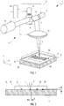
- FIG. 1 illustrated embodiment of a device according to the invention is essentially a conventional laser marking device, which - as will be explained below - has been modified accordingly for use with the inventive method.
- a target 2 for example a steel plate 2 or a steel foil, on which the workpiece W to be marked is placed with the surface O to be marked.
- a laser beam generating device 4 is used with a laser beam source 5, which generates a laser beam L having a wavelength in which the workpiece W to be marked is transmissive.
- the laser beam generating device 4 has, in addition to the laser beam source 5, a beam guiding device 12 in the form of a deflection unit 12 with two deflection mirrors 6, 8 driven by drive motors 7, 9, which are tilted vertically in two for tilting the laser beam L. Take care of directions. Coupled to this beam guiding device 12 or deflecting unit 12 is a focusing device 11, for example a plan field lens or F-theta objective 11 with an F-theta lens. In FIG. 1 the focusing device 11 is shown schematically only by the F-theta lens. The deflection unit 12 may be formed together with this F-theta lens 11 as a unit.
- the F-theta objective 11 deflect the laser beam L, which is deflected at a certain angle by the deflecting mirrors 6, 8, into a plane-parallel plane, which is located in the FIG. 1 shown coordinate system in the x- and y-direction extending plane, which here is preferably located exactly on the target surface 3 to focus.
- a plane-parallel plane which is located in the FIG. 1 shown coordinate system in the x- and y-direction extending plane, which here is preferably located exactly on the target surface 3 to focus.
- another point is hit in this xy plane.
- the focus F of the laser beam L can be moved in any desired manner along a specific marking track given by the marking image B, here for example the word "Panasonic".
- the complete deflection unit 12 with the F-theta objective 11 can also be a commercially available unit, as used in previous laser marking systems.
- the laser beam source 5 and the deflection unit 12 are actuated by the F-theta objective 11 via a control unit 10.
- a commercially available control unit 10 can be used, which must be programmed accordingly, so that the focus F, which is set automatically by the control unit 10 can be set as intended on the target surface 3 or just below the target surface 3.
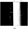
- the penetration depth t of the metal particles into a glass substrate can be more than 30 ⁇ m at a marking.
- FIG. 3 shows a micrograph (500x magnification), from which the diffusion channels and the penetration depth can be seen. At one point, the penetration depth t was measured. It is about 48 microns here.
- a FAYb laser with an average power of 12 watts was used. This is a pulsed laser with a laser peak power of up to 20 kW with a 20 ns pulse.
- the pulse repetition time can be set in this system from 10 ⁇ s to 50 ⁇ s.
- the objective was positioned 190 mm from the target surface 3 and the focus F was set directly on the target surface 3. The beam diameter d is then in the focus F about 60 microns (see FIG. 2 ). With this setting in focus, the laser has a power density of approx. 4,000 W / mm 2 .
- metal foils such as aluminum foil
- target materials For example, easy-to-read marks were achieved when using aluminum foil with a laser power of 5 watts, a feed rate of 1,000 mm / s and a pulse repetition time of 50 ⁇ s.
- the use of metal foil is advantageous under certain production conditions, if a specific positioning of the workpiece to be marked on a target surface is too complex and can be applied relatively easily to the workpiece during the production cycle, a metal foil.
Landscapes
- Chemical & Material Sciences (AREA)
- Optics & Photonics (AREA)
- Physics & Mathematics (AREA)
- Engineering & Computer Science (AREA)
- Life Sciences & Earth Sciences (AREA)
- Toxicology (AREA)
- Health & Medical Sciences (AREA)
- Chemical Kinetics & Catalysis (AREA)
- General Chemical & Material Sciences (AREA)
- Geochemistry & Mineralogy (AREA)
- Materials Engineering (AREA)
- Organic Chemistry (AREA)
- Laser Beam Processing (AREA)
- Surface Treatment Of Glass (AREA)
- Thermal Transfer Or Thermal Recording In General (AREA)
Claims (14)
- Procédé destiné à empreindre une structure (M) dans une surface (O) d'une pièce d'oeuvre (W) transparente dans une certaine gamme de longueurs d'onde, lors duquel on met en contact la surface (O) à structurer avec une surface cible (3) contenant une matière cible et à l'aide d'un rayon laser (2), dont la longueur d'onde se situe dans la certaine gamme de longueurs d'onde, on introduit de l'énergie à travers la pièce d'oeuvre (W), au moins sur une position dans la zone limite (G) de la surface (O) à structurer de la pièce d'oeuvre (W) et de la surface cible (3) de telle sorte que sur la position concernée, de la matière cible se dépose dans la surface (O) à structurer,
caractérisé en ce
qu'on utilise un rayon laser (L) pulsé, à un taux de répétition d'impulsions compris entre 20 kHz et 100 kHz , que l'on focalise de telle sorte que le foyer se trouve sur ou sous la surface cible, le rayon laser présentant dans le foyer une densité de puissance (puissance moyenne du laser par rapport à la surface focale) de plus de 2000 W/mm2. - Procédé selon la revendication 1, caractérisé en ce que la pièce d'oeuvre (W) est en verre.
- Procédé selon la revendication 1 ou la revendication 2, caractérisé en ce que la matière cible est un métal.
- Procédé selon la revendication 3, caractérisé en ce que la matière cible est un acier.
- Procédé selon l'une quelconque des revendications précédentes, caractérisé en ce que la structure (M) est conçue pour le marquage de la pièce d'oeuvre (W).
- Procédé selon l'une quelconque des revendications précédentes, caractérisé en ce qu'on déplace le foyer (F) du rayon laser (L) le long d'une piste de structuration prédéfinie selon un motif de structuration (B), à une vitesse d'avance supérieure à 70 mm/seconde, de manière particulièrement préférée, supérieure à 100 mm/seconde.
- Procédé selon l'une quelconque des revendications précédentes, caractérisé en ce que la structuration s'effectue de telle sorte qu'au moins en un endroit, des particules de la matière cible pénètrent à une profondeur d'au moins environ 15 µm, de préférence d'au moins environ 30 µm dans la surface à structurer.
- Procédé selon l'une quelconque des revendications précédentes, caractérisé en ce qu'on commande le rayon laser de telle sorte que, lors de la structuration, la température dans la surface à structurer soit inférieure à la température de fusion de la matière de la pièce d'oeuvre.
- Procédé selon l'une quelconque des revendications précédentes, caractérisé en ce que dans le foyer, le rayon laser présente une densité de puissance supérieure à environ 3 kW/mm2, de préférence supérieure à environ 10 kW/mm2, de manière particulièrement préférée, supérieure à env. 100 kW/mm2.
- Procédé selon l'une quelconque des revendications précédentes, caractérisé en ce que le diamètre focal est inférieur à 60 µm, de préférence inférieur à 40 µm.
- Procédé selon l'une quelconque des revendications précédentes, caractérisé en ce que la durée d'impulsion des impulsions laser est inférieure à 100 ns, de préférence inférieure à 20 ns.
- Procédé selon l'une quelconque des revendications précédentes, caractérisé en ce que la puissance de crête des impulsions laser est supérieure à 10 kW, de préférence supérieure à 25 kW.
- Dispositif (1) destiné à empreindre une structure (M) dans une surface (O) d'une pièce d'oeuvre (W) transparente dans une certaine gamme de longueurs d'onde, comprenant- une surface cible (3) contenant une matière cible pour la mise en contact avec la surface (O) à structurer de la pièce d'oeuvre (W),- un système de génération d'un rayon laser (4) pour la génération d'un rayon laser (L), dont la longueur d'onde se situe dans la certaine gamme de longueurs d'onde, le système de génération du rayon laser (4) étant conçu et placé de telle sorte, qu'à travers une pièce d'oeuvre (W) contactant la surface cible (3), à l'aide du rayon laser (L) au moins sur une position, de l'énergie soit susceptible d'être introduite dans la zone limite (G) de la surface (O) à structurer de la pièce d'oeuvre (W) et de la surface cible (3) de sorte que sur la position concernée, de matière cible se dépose dans la surface (O) à structurer,caractérisé en ce que le système de génération d'un rayon laser (4) est conçu de sorte à générer un rayon laser (L) pulsé avec un taux de répétition d'impulsion compris entre 20 kHz et 100 kHz et comporte un système de focalisation (11) et un système de commande (10) lequel, lors du processus de structuration focalise le rayon laser (L) sur ou juste en dessous de la surface cible (3), le rayon laser présentant dans le foyer une densité de puissance (puissance moyenne du laser par rapport à la surface focale) de plus de 2000 W/mm2.
- Dispositif selon la revendication 13, caractérisé en ce que le système de génération d'un rayon laser (4) comporte un système de guidage des rayons (12) pour déplacer le foyer du laser (F) le long d'une piste de structuration prédéfinie par un motif de structuration (B).
Applications Claiming Priority (2)
| Application Number | Priority Date | Filing Date | Title |
|---|---|---|---|
| DE102007018402A DE102007018402A1 (de) | 2007-04-17 | 2007-04-17 | Verfahren zum Einbringen einer Struktur in eine Oberfläche eines transparenten Werkstücks |
| PCT/EP2008/002840 WO2008125273A1 (fr) | 2007-04-17 | 2008-04-10 | Procédé pour mettre en place une structure dans une surface d'une pièce à usiner transparente |
Publications (2)
| Publication Number | Publication Date |
|---|---|
| EP2144728A1 EP2144728A1 (fr) | 2010-01-20 |
| EP2144728B1 true EP2144728B1 (fr) | 2017-01-04 |
Family
ID=39535712
Family Applications (1)
| Application Number | Title | Priority Date | Filing Date |
|---|---|---|---|
| EP08735149.0A Not-in-force EP2144728B1 (fr) | 2007-04-17 | 2008-04-10 | Procédé pour mettre en place une structure dans une surface d'une pièce à usiner transparente |
Country Status (6)
| Country | Link |
|---|---|
| US (1) | US8399798B2 (fr) |
| EP (1) | EP2144728B1 (fr) |
| JP (1) | JP5465170B2 (fr) |
| CN (1) | CN101678502B (fr) |
| DE (1) | DE102007018402A1 (fr) |
| WO (1) | WO2008125273A1 (fr) |
Cited By (1)
| Publication number | Priority date | Publication date | Assignee | Title |
|---|---|---|---|---|
| CN111230320A (zh) * | 2020-03-16 | 2020-06-05 | 深圳泰德激光科技有限公司 | 一种阳极氧化铝表面的激光打标方法 |
Families Citing this family (23)
| Publication number | Priority date | Publication date | Assignee | Title |
|---|---|---|---|---|
| DE102007018402A1 (de) * | 2007-04-17 | 2008-10-23 | Panasonic Electric Works Europe Ag | Verfahren zum Einbringen einer Struktur in eine Oberfläche eines transparenten Werkstücks |
| DE102007028042B3 (de) * | 2007-06-14 | 2008-08-07 | Universität Zu Lübeck | Verfahren zur Laserbearbeitung transparenter Materialien |
| DE102008058535A1 (de) * | 2008-11-21 | 2010-05-27 | Tesa Se | Verfahren zur Materialbearbeitung mit energiereicher Strahlung |
| JP6046329B2 (ja) * | 2010-01-08 | 2016-12-14 | 早川ゴム株式会社 | レーザー光を用いた接合方法 |
| HUE024418T2 (en) * | 2010-04-30 | 2016-01-28 | Becton Dickinson France | Procedure for marking a transparent container |
| ES2723791T3 (es) * | 2011-09-23 | 2019-09-02 | Boegli Gravures Sa | Método y dispositivo para producir una superficie estructurada sobre un rodillo de estampación de acero |
| PL2780172T3 (pl) * | 2011-11-17 | 2016-09-30 | Znaczony laserowo półwyrób polimerowy | |
| CN103253197B (zh) * | 2012-10-08 | 2016-08-31 | 上海博迩森汽车配件有限公司 | 后视镜镜片加工方法 |
| DE102012219249A1 (de) * | 2012-10-22 | 2014-02-13 | Bundesdruckerei Gmbh | Vorrichtung zur Laserpersonalisierung von Sicherheitselementen |
| EP2924820A4 (fr) | 2012-11-20 | 2016-07-06 | Univ Kyushu Nat Univ Corp | Appareil d'usinage laser et procédé d'usinage laser |
| EP3047932B1 (fr) * | 2015-01-21 | 2018-12-26 | Agie Charmilles New Technologies SA | Procédé d'ablation par laser en vu de graver une surface avec optimisation de zone de traitement, avec programme et machine correspondants |
| CA2931245C (fr) | 2015-05-26 | 2023-07-25 | National Research Council Of Canada | Surface metallique a relief karstifie, formation de ladite surface et interface electrochimique metallique de zone de surface elevee |
| GB201603991D0 (en) * | 2016-03-08 | 2016-04-20 | Univ Dundee | Processing method and apparatus |
| DE102016203363A1 (de) * | 2016-03-02 | 2017-09-07 | Bayerische Motoren Werke Aktiengesellschaft | Verfahren zum stoffschlüssigen Verbinden eines Aluminiumgussbauteils mit einem Fügepartner und Bauteil |
| CN105710538A (zh) * | 2016-04-22 | 2016-06-29 | 中国电子科技集团公司第十三研究所 | 玻璃晶圆激光标识的制作方法 |
| GB201609086D0 (en) * | 2016-05-20 | 2016-07-06 | Spi Lasers Uk Ltd | Method for creating a mark with a desired colour on an article |
| DE102016122113A1 (de) * | 2016-11-17 | 2018-05-17 | Karlsruher Institut für Technologie | Vorrichtung zur Identifikation von Gegenständen und Lebewesen in Wasser sowie Verfahren zu Herstellung und Anwendung der Vorrichtung und deren Verwendung |
| CN106335289A (zh) * | 2016-11-18 | 2017-01-18 | 深圳英诺激光科技有限公司 | 一种在透明材料上进行白色或彩色打标的设备及方法 |
| JP6334074B1 (ja) * | 2017-05-23 | 2018-05-30 | 堺ディスプレイプロダクト株式会社 | 素子基板の製造方法およびレーザクリーニング装置 |
| US11104127B2 (en) * | 2017-06-23 | 2021-08-31 | Hp Indigo B.V. | Material displacement |
| US20220402816A1 (en) * | 2019-09-26 | 2022-12-22 | Saverglass | Method for decoratively marking glass articles at high temperature by laser |
| WO2022180775A1 (fr) * | 2021-02-26 | 2022-09-01 | 国立大学法人名古屋工業大学 | Dispositif de traitement au laser, procédé de détection d'épaisseur, et dispositif de détection d'épaisseur |
| CN114083156A (zh) * | 2021-12-31 | 2022-02-25 | 杭州银湖激光科技有限公司 | 一种透明材料的激光加工方法 |
Citations (5)
| Publication number | Priority date | Publication date | Assignee | Title |
|---|---|---|---|---|
| DE19517625A1 (de) * | 1995-05-13 | 1996-11-14 | Budenheim Rud A Oetker Chemie | Verfahren zum musterförmigen Bedrucken fester Substratoberflächen |
| DE19637255C1 (de) * | 1996-09-13 | 1997-12-11 | Jenoptik Jena Gmbh | Verfahren zum indirekten Beschriften von transparenten Materialien |
| US5987920A (en) * | 1996-09-19 | 1999-11-23 | U.S. Philips Corporation | Method of producing a patterned surfacial marking on a transparent body |
| DE102006029941A1 (de) * | 2006-06-29 | 2008-01-03 | Calyxo Gmbh | Verfahren zum indirekten Beschriften transparenter Materialien |
| DE102007018402A1 (de) * | 2007-04-17 | 2008-10-23 | Panasonic Electric Works Europe Ag | Verfahren zum Einbringen einer Struktur in eine Oberfläche eines transparenten Werkstücks |
Family Cites Families (11)
| Publication number | Priority date | Publication date | Assignee | Title |
|---|---|---|---|---|
| FI103396B1 (fi) * | 1994-03-24 | 1999-06-30 | Laserplus Oy | Menetelmä ja laite merkkausten tekemiseksi lasipintaan |
| JP3616679B2 (ja) * | 1995-09-07 | 2005-02-02 | カルソニックカンセイ株式会社 | 端部閉塞パイプおよび熱交換器用ヘッダー |
| US5761111A (en) * | 1996-03-15 | 1998-06-02 | President And Fellows Of Harvard College | Method and apparatus providing 2-D/3-D optical information storage and retrieval in transparent materials |
| DE69704698T2 (de) * | 1996-12-27 | 2002-01-31 | Miyachi Technos Corp., Noda | Verfahren zur Beschriftung eines Gegenstands, dass ein Laserstrahl verwendet |
| US6281471B1 (en) * | 1999-12-28 | 2001-08-28 | Gsi Lumonics, Inc. | Energy-efficient, laser-based method and system for processing target material |
| US6929886B2 (en) * | 2001-01-02 | 2005-08-16 | U-C-Laser Ltd. | Method and apparatus for the manufacturing of reticles |
| JP4246645B2 (ja) * | 2003-01-28 | 2009-04-02 | 有限会社岩倉溶接工業所 | レーザによるカラーマーキング方法 |
| JP2006523154A (ja) * | 2003-03-13 | 2006-10-12 | コーニンクレッカ フィリップス エレクトロニクス エヌ ヴィ | マーキング方法およびマーキングされた対象 |
| JP2004351746A (ja) * | 2003-05-29 | 2004-12-16 | Central Glass Co Ltd | レーザ走査によるガラスの描画方法 |
| CN1603888A (zh) * | 2004-11-05 | 2005-04-06 | 中国科学院上海光学精密机械研究所 | 飞秒激光相干技术传输周期微结构的方法 |
| US7626138B2 (en) * | 2005-09-08 | 2009-12-01 | Imra America, Inc. | Transparent material processing with an ultrashort pulse laser |
-
2007
- 2007-04-17 DE DE102007018402A patent/DE102007018402A1/de not_active Withdrawn
-
2008
- 2008-04-10 EP EP08735149.0A patent/EP2144728B1/fr not_active Not-in-force
- 2008-04-10 US US12/596,521 patent/US8399798B2/en not_active Expired - Fee Related
- 2008-04-10 WO PCT/EP2008/002840 patent/WO2008125273A1/fr active Application Filing
- 2008-04-10 JP JP2010503386A patent/JP5465170B2/ja active Active
- 2008-04-10 CN CN2008800171775A patent/CN101678502B/zh not_active Expired - Fee Related
Patent Citations (5)
| Publication number | Priority date | Publication date | Assignee | Title |
|---|---|---|---|---|
| DE19517625A1 (de) * | 1995-05-13 | 1996-11-14 | Budenheim Rud A Oetker Chemie | Verfahren zum musterförmigen Bedrucken fester Substratoberflächen |
| DE19637255C1 (de) * | 1996-09-13 | 1997-12-11 | Jenoptik Jena Gmbh | Verfahren zum indirekten Beschriften von transparenten Materialien |
| US5987920A (en) * | 1996-09-19 | 1999-11-23 | U.S. Philips Corporation | Method of producing a patterned surfacial marking on a transparent body |
| DE102006029941A1 (de) * | 2006-06-29 | 2008-01-03 | Calyxo Gmbh | Verfahren zum indirekten Beschriften transparenter Materialien |
| DE102007018402A1 (de) * | 2007-04-17 | 2008-10-23 | Panasonic Electric Works Europe Ag | Verfahren zum Einbringen einer Struktur in eine Oberfläche eines transparenten Werkstücks |
Cited By (2)
| Publication number | Priority date | Publication date | Assignee | Title |
|---|---|---|---|---|
| CN111230320A (zh) * | 2020-03-16 | 2020-06-05 | 深圳泰德激光科技有限公司 | 一种阳极氧化铝表面的激光打标方法 |
| CN111230320B (zh) * | 2020-03-16 | 2022-05-17 | 深圳泰德激光技术股份有限公司 | 一种阳极氧化铝表面的激光打标方法 |
Also Published As
| Publication number | Publication date |
|---|---|
| US8399798B2 (en) | 2013-03-19 |
| DE102007018402A1 (de) | 2008-10-23 |
| JP5465170B2 (ja) | 2014-04-09 |
| EP2144728A1 (fr) | 2010-01-20 |
| CN101678502A (zh) | 2010-03-24 |
| JP2010524692A (ja) | 2010-07-22 |
| US20100108651A1 (en) | 2010-05-06 |
| WO2008125273A1 (fr) | 2008-10-23 |
| CN101678502B (zh) | 2013-07-10 |
Similar Documents
| Publication | Publication Date | Title |
|---|---|---|
| EP2144728B1 (fr) | Procédé pour mettre en place une structure dans une surface d'une pièce à usiner transparente | |
| EP2184127B1 (fr) | Procédé de marquage au laser, utilisation d'un dispositif de marquage au laser et élément optique | |
| EP1262315B1 (fr) | Méthode et dispositif de fabrication d'une plaque d'impression | |
| DE69816107T2 (de) | Laserbeschriftungsverfahren | |
| EP1871566B1 (fr) | Procede de polissage fin/structuration de matieres dielectriques thermosensibles au moyen d'un rayonnement laser | |
| EP0176872B1 (fr) | Dispositif pour le changement sans contact de la surface d'un objet | |
| DE2719275A1 (de) | Verfahren und vorrichtung fuer die materialabtragende bearbeitung von getrennten, in einem vorgegebenen muster angeordneten flaechen auf einem sich kontinuierlich bewegenden gegenstand | |
| DE3731398A1 (de) | Verfahren zum erzeugen einer kennzeichnung und/oder markierung auf einer brillenlinse | |
| WO2007012215A1 (fr) | Procede et dispositif de structuration ciblee d'une surface a l'aide d'un systeme laser | |
| DE1960959B2 (de) | Verfahren zur Herstellung einer Druckform | |
| DE1959853A1 (de) | Verfahren zum Eingravieren eines Zeichens,Symbols,dekorativen Musters od.dgl. in die Oberflaeche eines Gegenstandes sowie Vorrichtung zur Durchfuehrung eines solchen Verfahrens | |
| EP1262316A1 (fr) | Méthode et dispositif de fabrication d'une plaque d'impression | |
| DE102012011343A1 (de) | Vorrichtung und Verfahren zur Interferenzstrukturierung von Proben sowie dergestalt strukturierte Proben | |
| EP1051365B1 (fr) | Procede pour produire une marque dans un corps en verre | |
| DE202012012732U1 (de) | Prägewalze aus Stahl mit einer strukturierten Oberfläche und Vorrichtung zum Erzeugen der strukturierten Oberfläche | |
| EP0743128B1 (fr) | Procédé et dispositif pour le marquage de produits en matériaux transparents (solides) au moyen d'un laser | |
| DE19736110C2 (de) | Verfahren und Vorrichtung zur grat- und schmelzfreien Mikrobearbeitung von Werkstücken | |
| EP3015279B1 (fr) | Procédé de fabrication d'un élément de sécurité comprenant une image lenticulaire | |
| DE10234002B4 (de) | Verfahren zum Markieren von Glas | |
| DE102013002222B4 (de) | Verfahren zur Modifikation der Oberfläche eines Metalls | |
| EP1379477A1 (fr) | Procede de production de structures colorees sur verre | |
| WO2002030610A1 (fr) | Procede pour caracteriser et notamment pour marquer des surfaces d'elements optiques au moyen de lumiere ultraviolette | |
| DE10162111A1 (de) | Verfahren und Vorrichtung zur Veränderung der komplexen Brechzahl mittels elektromagnetischer Strahlung im Inneren von für diese Strahlung durchlässigen Bauteilen | |
| DE3402871C2 (de) | Verfahren zum Beschriften von transparenten Bauelementen mit einem Neodym-YAG-Laser | |
| DE102005055174B3 (de) | Verfahren zum Abtrag von lichtdurchlässigen Materialien mit Laserstrahlung und Vorrichtung hierfür |
Legal Events
| Date | Code | Title | Description |
|---|---|---|---|
| PUAI | Public reference made under article 153(3) epc to a published international application that has entered the european phase |
Free format text: ORIGINAL CODE: 0009012 |
|
| 17P | Request for examination filed |
Effective date: 20091009 |
|
| AK | Designated contracting states |
Kind code of ref document: A1 Designated state(s): AT BE BG CH CY CZ DE DK EE ES FI FR GB GR HR HU IE IS IT LI LT LU LV MC MT NL NO PL PT RO SE SI SK TR |
|
| AX | Request for extension of the european patent |
Extension state: AL BA MK RS |
|
| DAX | Request for extension of the european patent (deleted) | ||
| 17Q | First examination report despatched |
Effective date: 20120529 |
|
| RAP1 | Party data changed (applicant data changed or rights of an application transferred) |
Owner name: PANASONIC ELECTRIC WORKS EUROPE AG |
|
| REG | Reference to a national code |
Ref country code: DE Ref legal event code: R079 Ref document number: 502008014932 Country of ref document: DE Free format text: PREVIOUS MAIN CLASS: B23K0026000000 Ipc: C03C0021000000 |
|
| RIC1 | Information provided on ipc code assigned before grant |
Ipc: C03C 21/00 20060101AFI20160715BHEP |
|
| GRAP | Despatch of communication of intention to grant a patent |
Free format text: ORIGINAL CODE: EPIDOSNIGR1 |
|
| INTG | Intention to grant announced |
Effective date: 20160908 |
|
| GRAS | Grant fee paid |
Free format text: ORIGINAL CODE: EPIDOSNIGR3 |
|
| GRAA | (expected) grant |
Free format text: ORIGINAL CODE: 0009210 |
|
| AK | Designated contracting states |
Kind code of ref document: B1 Designated state(s): AT BE BG CH CY CZ DE DK EE ES FI FR GB GR HR HU IE IS IT LI LT LU LV MC MT NL NO PL PT RO SE SI SK TR |
|
| REG | Reference to a national code |
Ref country code: GB Ref legal event code: FG4D Free format text: NOT ENGLISH |
|
| REG | Reference to a national code |
Ref country code: CH Ref legal event code: EP |
|
| REG | Reference to a national code |
Ref country code: AT Ref legal event code: REF Ref document number: 859066 Country of ref document: AT Kind code of ref document: T Effective date: 20170115 |
|
| REG | Reference to a national code |
Ref country code: IE Ref legal event code: FG4D Free format text: LANGUAGE OF EP DOCUMENT: GERMAN |
|
| REG | Reference to a national code |
Ref country code: DE Ref legal event code: R096 Ref document number: 502008014932 Country of ref document: DE |
|
| REG | Reference to a national code |
Ref country code: FR Ref legal event code: PLFP Year of fee payment: 10 |
|
| REG | Reference to a national code |
Ref country code: LT Ref legal event code: MG4D Ref country code: NL Ref legal event code: MP Effective date: 20170104 |
|
| PG25 | Lapsed in a contracting state [announced via postgrant information from national office to epo] |
Ref country code: NL Free format text: LAPSE BECAUSE OF FAILURE TO SUBMIT A TRANSLATION OF THE DESCRIPTION OR TO PAY THE FEE WITHIN THE PRESCRIBED TIME-LIMIT Effective date: 20170104 |
|
| PG25 | Lapsed in a contracting state [announced via postgrant information from national office to epo] |
Ref country code: NO Free format text: LAPSE BECAUSE OF FAILURE TO SUBMIT A TRANSLATION OF THE DESCRIPTION OR TO PAY THE FEE WITHIN THE PRESCRIBED TIME-LIMIT Effective date: 20170404 Ref country code: IS Free format text: LAPSE BECAUSE OF FAILURE TO SUBMIT A TRANSLATION OF THE DESCRIPTION OR TO PAY THE FEE WITHIN THE PRESCRIBED TIME-LIMIT Effective date: 20170504 Ref country code: GR Free format text: LAPSE BECAUSE OF FAILURE TO SUBMIT A TRANSLATION OF THE DESCRIPTION OR TO PAY THE FEE WITHIN THE PRESCRIBED TIME-LIMIT Effective date: 20170405 Ref country code: LT Free format text: LAPSE BECAUSE OF FAILURE TO SUBMIT A TRANSLATION OF THE DESCRIPTION OR TO PAY THE FEE WITHIN THE PRESCRIBED TIME-LIMIT Effective date: 20170104 Ref country code: FI Free format text: LAPSE BECAUSE OF FAILURE TO SUBMIT A TRANSLATION OF THE DESCRIPTION OR TO PAY THE FEE WITHIN THE PRESCRIBED TIME-LIMIT Effective date: 20170104 Ref country code: HR Free format text: LAPSE BECAUSE OF FAILURE TO SUBMIT A TRANSLATION OF THE DESCRIPTION OR TO PAY THE FEE WITHIN THE PRESCRIBED TIME-LIMIT Effective date: 20170104 |
|
| PG25 | Lapsed in a contracting state [announced via postgrant information from national office to epo] |
Ref country code: PT Free format text: LAPSE BECAUSE OF FAILURE TO SUBMIT A TRANSLATION OF THE DESCRIPTION OR TO PAY THE FEE WITHIN THE PRESCRIBED TIME-LIMIT Effective date: 20170504 Ref country code: SE Free format text: LAPSE BECAUSE OF FAILURE TO SUBMIT A TRANSLATION OF THE DESCRIPTION OR TO PAY THE FEE WITHIN THE PRESCRIBED TIME-LIMIT Effective date: 20170104 Ref country code: BG Free format text: LAPSE BECAUSE OF FAILURE TO SUBMIT A TRANSLATION OF THE DESCRIPTION OR TO PAY THE FEE WITHIN THE PRESCRIBED TIME-LIMIT Effective date: 20170404 Ref country code: LV Free format text: LAPSE BECAUSE OF FAILURE TO SUBMIT A TRANSLATION OF THE DESCRIPTION OR TO PAY THE FEE WITHIN THE PRESCRIBED TIME-LIMIT Effective date: 20170104 Ref country code: ES Free format text: LAPSE BECAUSE OF FAILURE TO SUBMIT A TRANSLATION OF THE DESCRIPTION OR TO PAY THE FEE WITHIN THE PRESCRIBED TIME-LIMIT Effective date: 20170104 Ref country code: PL Free format text: LAPSE BECAUSE OF FAILURE TO SUBMIT A TRANSLATION OF THE DESCRIPTION OR TO PAY THE FEE WITHIN THE PRESCRIBED TIME-LIMIT Effective date: 20170104 |
|
| REG | Reference to a national code |
Ref country code: DE Ref legal event code: R097 Ref document number: 502008014932 Country of ref document: DE |
|
| PG25 | Lapsed in a contracting state [announced via postgrant information from national office to epo] |
Ref country code: IT Free format text: LAPSE BECAUSE OF FAILURE TO SUBMIT A TRANSLATION OF THE DESCRIPTION OR TO PAY THE FEE WITHIN THE PRESCRIBED TIME-LIMIT Effective date: 20170104 Ref country code: EE Free format text: LAPSE BECAUSE OF FAILURE TO SUBMIT A TRANSLATION OF THE DESCRIPTION OR TO PAY THE FEE WITHIN THE PRESCRIBED TIME-LIMIT Effective date: 20170104 Ref country code: CZ Free format text: LAPSE BECAUSE OF FAILURE TO SUBMIT A TRANSLATION OF THE DESCRIPTION OR TO PAY THE FEE WITHIN THE PRESCRIBED TIME-LIMIT Effective date: 20170104 Ref country code: SK Free format text: LAPSE BECAUSE OF FAILURE TO SUBMIT A TRANSLATION OF THE DESCRIPTION OR TO PAY THE FEE WITHIN THE PRESCRIBED TIME-LIMIT Effective date: 20170104 Ref country code: RO Free format text: LAPSE BECAUSE OF FAILURE TO SUBMIT A TRANSLATION OF THE DESCRIPTION OR TO PAY THE FEE WITHIN THE PRESCRIBED TIME-LIMIT Effective date: 20170104 |
|
| PLBE | No opposition filed within time limit |
Free format text: ORIGINAL CODE: 0009261 |
|
| STAA | Information on the status of an ep patent application or granted ep patent |
Free format text: STATUS: NO OPPOSITION FILED WITHIN TIME LIMIT |
|
| PG25 | Lapsed in a contracting state [announced via postgrant information from national office to epo] |
Ref country code: DK Free format text: LAPSE BECAUSE OF FAILURE TO SUBMIT A TRANSLATION OF THE DESCRIPTION OR TO PAY THE FEE WITHIN THE PRESCRIBED TIME-LIMIT Effective date: 20170104 |
|
| REG | Reference to a national code |
Ref country code: CH Ref legal event code: PL |
|
| 26N | No opposition filed |
Effective date: 20171005 |
|
| REG | Reference to a national code |
Ref country code: IE Ref legal event code: MM4A |
|
| PG25 | Lapsed in a contracting state [announced via postgrant information from national office to epo] |
Ref country code: MC Free format text: LAPSE BECAUSE OF FAILURE TO SUBMIT A TRANSLATION OF THE DESCRIPTION OR TO PAY THE FEE WITHIN THE PRESCRIBED TIME-LIMIT Effective date: 20170104 |
|
| PG25 | Lapsed in a contracting state [announced via postgrant information from national office to epo] |
Ref country code: SI Free format text: LAPSE BECAUSE OF FAILURE TO SUBMIT A TRANSLATION OF THE DESCRIPTION OR TO PAY THE FEE WITHIN THE PRESCRIBED TIME-LIMIT Effective date: 20170104 Ref country code: LI Free format text: LAPSE BECAUSE OF NON-PAYMENT OF DUE FEES Effective date: 20170430 Ref country code: CH Free format text: LAPSE BECAUSE OF NON-PAYMENT OF DUE FEES Effective date: 20170430 Ref country code: LU Free format text: LAPSE BECAUSE OF NON-PAYMENT OF DUE FEES Effective date: 20170410 |
|
| REG | Reference to a national code |
Ref country code: BE Ref legal event code: MM Effective date: 20170430 |
|
| REG | Reference to a national code |
Ref country code: FR Ref legal event code: PLFP Year of fee payment: 11 |
|
| PG25 | Lapsed in a contracting state [announced via postgrant information from national office to epo] |
Ref country code: IE Free format text: LAPSE BECAUSE OF NON-PAYMENT OF DUE FEES Effective date: 20170410 |
|
| PG25 | Lapsed in a contracting state [announced via postgrant information from national office to epo] |
Ref country code: BE Free format text: LAPSE BECAUSE OF NON-PAYMENT OF DUE FEES Effective date: 20170430 |
|
| REG | Reference to a national code |
Ref country code: AT Ref legal event code: MM01 Ref document number: 859066 Country of ref document: AT Kind code of ref document: T Effective date: 20170410 |
|
| PG25 | Lapsed in a contracting state [announced via postgrant information from national office to epo] |
Ref country code: AT Free format text: LAPSE BECAUSE OF NON-PAYMENT OF DUE FEES Effective date: 20170410 |
|
| PG25 | Lapsed in a contracting state [announced via postgrant information from national office to epo] |
Ref country code: MT Free format text: LAPSE BECAUSE OF FAILURE TO SUBMIT A TRANSLATION OF THE DESCRIPTION OR TO PAY THE FEE WITHIN THE PRESCRIBED TIME-LIMIT Effective date: 20170104 |
|
| PG25 | Lapsed in a contracting state [announced via postgrant information from national office to epo] |
Ref country code: HU Free format text: LAPSE BECAUSE OF FAILURE TO SUBMIT A TRANSLATION OF THE DESCRIPTION OR TO PAY THE FEE WITHIN THE PRESCRIBED TIME-LIMIT; INVALID AB INITIO Effective date: 20080410 |
|
| PG25 | Lapsed in a contracting state [announced via postgrant information from national office to epo] |
Ref country code: CY Free format text: LAPSE BECAUSE OF NON-PAYMENT OF DUE FEES Effective date: 20170104 |
|
| PG25 | Lapsed in a contracting state [announced via postgrant information from national office to epo] |
Ref country code: TR Free format text: LAPSE BECAUSE OF FAILURE TO SUBMIT A TRANSLATION OF THE DESCRIPTION OR TO PAY THE FEE WITHIN THE PRESCRIBED TIME-LIMIT Effective date: 20170104 |
|
| PGFP | Annual fee paid to national office [announced via postgrant information from national office to epo] |
Ref country code: GB Payment date: 20220425 Year of fee payment: 15 Ref country code: FR Payment date: 20220420 Year of fee payment: 15 Ref country code: DE Payment date: 20220419 Year of fee payment: 15 |
|
| REG | Reference to a national code |
Ref country code: DE Ref legal event code: R119 Ref document number: 502008014932 Country of ref document: DE |
|
| GBPC | Gb: european patent ceased through non-payment of renewal fee |
Effective date: 20230410 |
|
| PG25 | Lapsed in a contracting state [announced via postgrant information from national office to epo] |
Ref country code: GB Free format text: LAPSE BECAUSE OF NON-PAYMENT OF DUE FEES Effective date: 20230410 |
|
| PG25 | Lapsed in a contracting state [announced via postgrant information from national office to epo] |
Ref country code: GB Free format text: LAPSE BECAUSE OF NON-PAYMENT OF DUE FEES Effective date: 20230410 Ref country code: FR Free format text: LAPSE BECAUSE OF NON-PAYMENT OF DUE FEES Effective date: 20230430 Ref country code: DE Free format text: LAPSE BECAUSE OF NON-PAYMENT OF DUE FEES Effective date: 20231103 |