EP2575239A2 - Machine électrique et procédé de fabrication d'une machine électrique - Google Patents
Machine électrique et procédé de fabrication d'une machine électrique Download PDFInfo
- Publication number
- EP2575239A2 EP2575239A2 EP12184973A EP12184973A EP2575239A2 EP 2575239 A2 EP2575239 A2 EP 2575239A2 EP 12184973 A EP12184973 A EP 12184973A EP 12184973 A EP12184973 A EP 12184973A EP 2575239 A2 EP2575239 A2 EP 2575239A2
- Authority
- EP
- European Patent Office
- Prior art keywords
- commutator
- spring
- axial
- armature
- axial direction
- Prior art date
- Legal status (The legal status is an assumption and is not a legal conclusion. Google has not performed a legal analysis and makes no representation as to the accuracy of the status listed.)
- Withdrawn
Links
- 238000004519 manufacturing process Methods 0.000 title claims abstract description 5
- 238000000034 method Methods 0.000 title abstract description 5
- 238000003860 storage Methods 0.000 claims abstract description 21
- 239000007858 starting material Substances 0.000 claims description 28
- 238000002485 combustion reaction Methods 0.000 claims description 14
- 238000003780 insertion Methods 0.000 claims description 2
- 230000037431 insertion Effects 0.000 claims description 2
- 206010007134 Candida infections Diseases 0.000 abstract 1
- 208000007027 Oral Candidiasis Diseases 0.000 abstract 1
- 241000287411 Turdidae Species 0.000 abstract 1
- 201000003984 candidiasis Diseases 0.000 abstract 1
- 239000004033 plastic Substances 0.000 description 5
- 229920003023 plastic Polymers 0.000 description 5
- 230000006835 compression Effects 0.000 description 3
- 238000007906 compression Methods 0.000 description 3
- PXHVJJICTQNCMI-UHFFFAOYSA-N Nickel Chemical compound [Ni] PXHVJJICTQNCMI-UHFFFAOYSA-N 0.000 description 2
- 238000000576 coating method Methods 0.000 description 2
- 238000006073 displacement reaction Methods 0.000 description 2
- 230000002349 favourable effect Effects 0.000 description 2
- 230000002093 peripheral effect Effects 0.000 description 2
- OKTJSMMVPCPJKN-UHFFFAOYSA-N Carbon Chemical compound [C] OKTJSMMVPCPJKN-UHFFFAOYSA-N 0.000 description 1
- XEEYBQQBJWHFJM-UHFFFAOYSA-N Iron Chemical group [Fe] XEEYBQQBJWHFJM-UHFFFAOYSA-N 0.000 description 1
- 230000006978 adaptation Effects 0.000 description 1
- 229910052799 carbon Inorganic materials 0.000 description 1
- 239000011248 coating agent Substances 0.000 description 1
- 239000002131 composite material Substances 0.000 description 1
- 230000001419 dependent effect Effects 0.000 description 1
- 238000005304 joining Methods 0.000 description 1
- 239000000463 material Substances 0.000 description 1
- 229910052751 metal Inorganic materials 0.000 description 1
- 239000002184 metal Substances 0.000 description 1
- 150000002739 metals Chemical class 0.000 description 1
- 229910052759 nickel Inorganic materials 0.000 description 1
- 230000000704 physical effect Effects 0.000 description 1
- 239000004810 polytetrafluoroethylene Substances 0.000 description 1
- 229920001343 polytetrafluoroethylene Polymers 0.000 description 1
- 238000004393 prognosis Methods 0.000 description 1
- 230000002441 reversible effect Effects 0.000 description 1
- 239000000126 substance Substances 0.000 description 1
Images

Classifications
-
- F—MECHANICAL ENGINEERING; LIGHTING; HEATING; WEAPONS; BLASTING
- F02—COMBUSTION ENGINES; HOT-GAS OR COMBUSTION-PRODUCT ENGINE PLANTS
- F02N—STARTING OF COMBUSTION ENGINES; STARTING AIDS FOR SUCH ENGINES, NOT OTHERWISE PROVIDED FOR
- F02N15/00—Other power-operated starting apparatus; Component parts, details, or accessories, not provided for in, or of interest apart from groups F02N5/00 - F02N13/00
-
- H—ELECTRICITY
- H02—GENERATION; CONVERSION OR DISTRIBUTION OF ELECTRIC POWER
- H02K—DYNAMO-ELECTRIC MACHINES
- H02K5/00—Casings; Enclosures; Supports
- H02K5/04—Casings or enclosures characterised by the shape, form or construction thereof
- H02K5/16—Means for supporting bearings, e.g. insulating supports or means for fitting bearings in the bearing-shields
- H02K5/167—Means for supporting bearings, e.g. insulating supports or means for fitting bearings in the bearing-shields using sliding-contact or spherical cap bearings
- H02K5/1672—Means for supporting bearings, e.g. insulating supports or means for fitting bearings in the bearing-shields using sliding-contact or spherical cap bearings radially supporting the rotary shaft at both ends of the rotor
-
- F—MECHANICAL ENGINEERING; LIGHTING; HEATING; WEAPONS; BLASTING
- F02—COMBUSTION ENGINES; HOT-GAS OR COMBUSTION-PRODUCT ENGINE PLANTS
- F02N—STARTING OF COMBUSTION ENGINES; STARTING AIDS FOR SUCH ENGINES, NOT OTHERWISE PROVIDED FOR
- F02N11/00—Starting of engines by means of electric motors
-
- F—MECHANICAL ENGINEERING; LIGHTING; HEATING; WEAPONS; BLASTING
- F02—COMBUSTION ENGINES; HOT-GAS OR COMBUSTION-PRODUCT ENGINE PLANTS
- F02N—STARTING OF COMBUSTION ENGINES; STARTING AIDS FOR SUCH ENGINES, NOT OTHERWISE PROVIDED FOR
- F02N15/00—Other power-operated starting apparatus; Component parts, details, or accessories, not provided for in, or of interest apart from groups F02N5/00 - F02N13/00
- F02N15/02—Gearing between starting-engines and started engines; Engagement or disengagement thereof
- F02N15/022—Gearing between starting-engines and started engines; Engagement or disengagement thereof the starter comprising an intermediate clutch
-
- F—MECHANICAL ENGINEERING; LIGHTING; HEATING; WEAPONS; BLASTING
- F02—COMBUSTION ENGINES; HOT-GAS OR COMBUSTION-PRODUCT ENGINE PLANTS
- F02N—STARTING OF COMBUSTION ENGINES; STARTING AIDS FOR SUCH ENGINES, NOT OTHERWISE PROVIDED FOR
- F02N15/00—Other power-operated starting apparatus; Component parts, details, or accessories, not provided for in, or of interest apart from groups F02N5/00 - F02N13/00
- F02N15/02—Gearing between starting-engines and started engines; Engagement or disengagement thereof
- F02N15/04—Gearing between starting-engines and started engines; Engagement or disengagement thereof the gearing including disengaging toothed gears
- F02N15/043—Gearing between starting-engines and started engines; Engagement or disengagement thereof the gearing including disengaging toothed gears the gearing including a speed reducer
- F02N15/046—Gearing between starting-engines and started engines; Engagement or disengagement thereof the gearing including disengaging toothed gears the gearing including a speed reducer of the planetary type
-
- F—MECHANICAL ENGINEERING; LIGHTING; HEATING; WEAPONS; BLASTING
- F02—COMBUSTION ENGINES; HOT-GAS OR COMBUSTION-PRODUCT ENGINE PLANTS
- F02N—STARTING OF COMBUSTION ENGINES; STARTING AIDS FOR SUCH ENGINES, NOT OTHERWISE PROVIDED FOR
- F02N15/00—Other power-operated starting apparatus; Component parts, details, or accessories, not provided for in, or of interest apart from groups F02N5/00 - F02N13/00
- F02N15/02—Gearing between starting-engines and started engines; Engagement or disengagement thereof
- F02N15/04—Gearing between starting-engines and started engines; Engagement or disengagement thereof the gearing including disengaging toothed gears
- F02N15/06—Gearing between starting-engines and started engines; Engagement or disengagement thereof the gearing including disengaging toothed gears the toothed gears being moved by axial displacement
- F02N15/067—Gearing between starting-engines and started engines; Engagement or disengagement thereof the gearing including disengaging toothed gears the toothed gears being moved by axial displacement the starter comprising an electro-magnetically actuated lever
-
- H—ELECTRICITY
- H02—GENERATION; CONVERSION OR DISTRIBUTION OF ELECTRIC POWER
- H02K—DYNAMO-ELECTRIC MACHINES
- H02K2205/00—Specific aspects not provided for in the other groups of this subclass relating to casings, enclosures, supports
- H02K2205/03—Machines characterised by thrust bearings
Definitions
- the invention relates to an electric machine, in particular a starter device such as a starter, for starting an internal combustion engine, according to the preamble of claim 1.
- the invention relates to a method for producing an electric machine, in particular a starting device, for starting an internal combustion engine, according to the preamble of claim 10.
- the invention relates to a system with a starter or starter motor according to the preamble of the independent claims.
- the present invention starters and starters for vehicles with internal combustion engines, which have an electric machine with armature and commutator, wherein the armature has an armature shaft with corresponding armature bearing.
- starters with a starter relay for vehicles with internal combustion engines are known, which generally comprise a DC electric motor for driving the internal combustion engine.
- a relay fork lever system with a corresponding relay is responsible for a meshing or a hub in the sprocket.
- a stroke also referred to as distance, or more precisely a meshing movement
- a relay pulls a fork lever to the rear. This is done by a corresponding energization of the relay.
- Such starters have an electric motor. This electric motor has a stator which is designed as a magnet. Next, the electric motor has a rotor.
- the rotor has an armature formed of a coil with iron core, which is rotatably mounted in a magnetic field between pole pieces of the stator.
- a current supply for the armature via a segmented commutator and sliding contacts, so-called commutator brushes.
- commutator brushes When the rotor is energized, a magnetic field is also produced which interacts with the magnetic field of the stator.
- anchor shafts are used, which are floating.
- axial securing devices are known.
- Such Axialommes coupled include a seated on the armature shaft lock washer. The seat of the lock washer in the groove is subject to tolerances. Due to a tolerance chain of several items with respect to an anchor, the individual tolerances add during assembly of the starter, so that the armature shaft can have a AxiallCodesspiel, which can be some 1/10 millimeters and more.
- a starting device for internal combustion engines with a starter motor is known, the drive shaft is connected via a countershaft with an output shaft in operative connection, which is part of a Einspurgetriebes with freewheel and starter pinion, which is arranged axially displaceably on the output shaft and by axial displacement with the ring gear of the starter gear
- Internal combustion engine is brought into engagement, wherein on the output shaft behind the starting pinion - with respect to the direction of the starter motor - a stop device for the starter pinion is arranged in the end region of its movement during engagement with the ring gear, wherein the stop device comprises an axially acting spring element.
- the electric machine according to the invention and the method according to the invention with the features of the corresponding main claim or subordinate claim have the advantage over the prior art that in an electric machine, in particular a starting device such as a starter, for starting an internal combustion engine comprising a commutator armature Unit with an outstanding therefrom in the axial direction armature shaft which is floatingly mounted at its one end by means of a Kommutatorlagers, wherein between the commutator armature unit and Kommutatorlager an axially adjustable axial securing device is provided, the axial play of the armature shaft can be minimized by the change of the axial securing device.
- a starting device such as a starter
- a commutator armature Unit with an outstanding therefrom in the axial direction armature shaft which is floatingly mounted at its one end by means of a Kommutatorlagers, wherein between the commutator armature unit and Kommutatorlager an axially adjustable axial securing device is provided, the axial play of
- the axial securing device is independent of an axial play of the armature shaft and is independently changeable in the axial direction, the Axialankerlteilsspiel can be reduced from a few 1/10 millimeters to a few 1/100 millimeters. This significantly reduces the wear of a commutator system of the starter device and especially of the carbon brushes.
- the axial play or anchor longitudinal play is no longer defined by the tolerances of several relatively inaccurately manufactured components.
- the change of the axial securing device in the axial direction is preferably reversible, in particular elastic. As a result, an adaptation to changed longitudinal games is possible.
- the electric machine preferably comprises an electric motor with rotor and stator.
- the electric machine is designed as a starting device for an internal combustion engine as a so-called starter or starter motor.
- This includes a commutator armature unit with a commutator with commutator brushes.
- the commutator brushes are held in a brush holder.
- the commutator armature unit comprises an armature with a rotatable armature shaft. Power is supplied to the armature via the commutator and the armature shaft is driven.
- the axial securing device comprises a spring-storage device which is elastically deformable in the axial direction.
- the commutator is mounted in the electric machine by means of the commutator.
- the commutator bearing is formed on one side of the commutator, for example, as part of a housing cover or the like. Between the commutator and the housing cover, the spring-storage device is arranged.
- the spring-storage device is designed as a ring with resilient elements, in particular as a spring ring.
- the axial securing device comprises a spring ring. This is wavy curved in the ring plane.
- the axial securing device is designed as a ring with spring elements projecting therefrom from the ring plane, such as spring arms and the like.
- a further embodiment of the present invention provides that the axial securing device is provided at least one thrust washer adjacent to the spring-loaded device.
- the thrust washer is kommutator Material or cover side, that is providable on each side of the spring-memory device.
- a plurality of discs on one or the other side of the spring-storage unit providable, for example, to set a width of the axial securing device.
- the axial securing device adjacent to each side of the spring-storage unit has at least one thrust washer, so that the spring-storage device is sandwiched between the thrust washers.
- the contact surfaces are realized on adjacent components by the thrust washers. Differences in the radial direction or circumferential direction of the armature shaft or the adjacent components are compensated so.
- a compact unit of the axial securing device is thus ensured in a simple manner.
- the armature shaft in the region of the spring-memory device formed groove-free.
- the axial fixing takes place via the distance between the commutator armature unit and the commutator bearing or the cover or the width of the Axialommes adopted, that is, the axial extent of spring storage unit and thrust washer (s).
- friction-reducing means be provided on the thrust washers and / or the spring-accumulator unit.
- friction-reducing means include in one embodiment, for example, lubricious plastics such as PTFE, PFA, etc., Sintered metals, coatings, for example with bearing material, bonded coating, chemical nickel and the like.
- the spring-accumulator unit and / or the thrust washer (s) extends circumferentially or radially beyond the armature shaft such that it is / are arranged in the axial direction between the commutator armature unit and the commutator bearing.
- the axial securing device has at least one width in the axial direction which corresponds to a distance between the commutator armature unit and commutator bearing and is preferably wider in the original state than the distance between the commutator armature unit and the commutator bearing.
- the axial storage device comprising the spring-storage unit has a width which corresponds approximately to the distance between the commutator armature unit and commutator.
- the width is greater than the distance, so that after assembly, the axial securing device is at least slightly biased. The ratio of width and distance can be adjusted depending on the application.
- Exemplary values for possible width to spacing ratios for a bias voltage are in a range of greater than or equal to 1 to about less than or equal to 1.5, preferably less than or equal to 1.4, and more preferably less than or equal to 1.3. Accordingly, any ratio is conceivable, for example, about 1; 1.025; 1.05; 1.075; 1.1; 1.15; 1.25; 1.3; 1.35; 1.4; 1.45; 1.5 and the like.
- the original state corresponds to a non-prestressed state.
- the axial securing device has, spaced from the spring-storage device, in particular on another side of the commutator bearing, an axial securing element, in particular a securing disk. In this way, a backup is additionally provided, which reduces a Axiallnaturesspiel.
- the inventive method with the features of the corresponding main claim or independent claim has the prior art over the advantage that in the manufacture of an electric machine according to the invention, in particular a starting device according to the invention, for cranking an internal combustion engine, comprising a commutator armature unit with an outstanding in the axial direction armature shaft which is floatingly mounted at its one end by means of a Kommutatorlagers, wherein prior to insertion of the armature shaft in the Kommutatorlager an axially adjustable axial securing means on the armature shaft surrounding this is positioned, in the assembled state, an axial play of the armature shaft is reduced. It is due to the variable properties no costly adjustment of the axial securing device required. Due to the changeable properties an auto adjustment takes place.
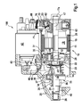
- Fig. 1 shows in a cross-sectional view designed as a starting device electrical machine 100 of an internal combustion engine with relay 42, also designed as a switching or engaging relay.
- a housing 10 of the electric machine 100 comprises a cylindrical housing part 11 and a cover 13, which are interconnected by screws, not shown.
- the cylindrical housing part 11 is closed at the rear by the cover 13, in the middle part of an outwardly directed, closed hub 14 is formed (see Fig. 2 ).
- a bearing 15 see Fig. 2
- the rear end 17 a of the drive shaft 17 of an electric starter motor 18 is mounted, whose armature is denoted by 19.
- Radially outside the armature 19 are on the wall of the housing part 11 more (permanent) magnets 20 of the starter motor 18.
- the front end of the drive shaft 17 is connected to a reduced diameter end portion 22 in a coaxially extending, not shown blind bore 23 of an output shaft 24 stored.
- the other end of the output shaft 24 is mounted in a housing part 11 closing bearing plate 25 and a molded-on this hub 26.
- a planet carrier 12 drives the output shaft 24, on which a freewheel 33 is arranged, whose inner ring 34 has an extension 35 (pinion), on which an outer toothing 36 is formed.
- the outer ring 37 of the freewheel 33 is connected via a coarse thread 38 with the output shaft 24.
- Einspurfeder 39 a By axial displacement of the freewheel 33, the external teeth 36 can be brought into engagement with a ring gear 40 of an internal combustion engine for the purpose of starting. This is done by means of a (engagement) relay 42, in which a magnet armature pivots a lever 44 via a projection 43 when switching on a current, which shifts the freewheel 33 to the left via a link 45, which lies between discs 46.
- the lever 44 is formed with two arms and by means of pins 48, pivotally mounted in a housing-fixed bearing 49. On this process is received only briefly, since not essential to the invention.
- the drive shaft 17 is near its rear bearing-side end 17a with a lock washer 51 (see Fig. 2 ) secured.
- This is approximately U-shaped - and is on the one hand at one end 52 of the lid 13, on the other hand at one end 15 a of the bearing 15 (see Fig. 2 ).
- a brush plate 53 which is screwed to the lid 13.
- the brush plate 53 is integrally formed.
- coals are arranged, which bear under spring pressure to a commutator 63, which on the drive shaft 17th is arranged.
- the coals are connected via connecting leads to a cable lug which is connected to a contact 68 of the engagement relay 42.
- the strands penetrate a seal 70, which is arranged in the housing part 11 in an opening 71.
- the brush plate 53 is fastened with screws 62 on the cover 13.
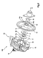
- FIG. 2 shows in perspective an exploded view of a section of another embodiment of the electric machine 100.
- the same reference numerals are used. A detailed description of already described components is eliminated.
- Fig. 2 an axial securing device 80 which can be changed in the axial direction A is shown.
- the axial securing device 80 is arranged in the axial direction A between the bearing point acting as a commutator bearing 15 and the commutator armature unit, more precisely the commutator 63.
- the axial securing device 80 comprises a spring-storage device, which is effective in the axial direction A.
- the spring-storage device comprises a spring ring 3, which is sandwiched between two thrust washers 4.
- the armature shaft 17 is formed groove-free.
- the axial securing device 80 surrounds the armature shaft 17 circumferentially and is thus fixed in a radial direction to the armature shaft 17 within a predetermined clearance.
- the spring washer 3 with the two stop disks 4 is arranged between the commutator 63 and the cover 13.
- the locking washer 51 is arranged as an axial securing element. This sits, together with a retaining ring 51a in an annular groove 50 of the armature shaft 17.
- the composite arrangement is also in the Fig. 3a and 3b shown.
- Figure 3a and 3b show a section of the starter after Fig. 2 in the ready state in a cross-sectional view and a perspective view.
- the sandwich-like arrangement - viewed in the axial direction A - from commutator armature unit, first thrust washer 4, spring washer 3, second thrust washer 4 and cover 13 can be seen.
- a width B of the thrust washers-spring disk arrangement shown schematically here in the relaxed state, that is, before joining the cranking wider than a distance D in the axial direction A between commutator armature unit and cover 13.
- the thrust washer spring washer assembly between commutator armature unit and cover 13 is clamped, that is, the spring washer 3 is biased.
- the width B of preloaded thrust washer spring washer assembly corresponds to the distance D in this state.
- an axial play or armature longitudinal play is reduced by the prestressed spring washer 3.
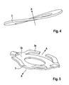
- Embodiments of the spring washer 51 are in 4 and 5 shown.
- FIG. 4 and FIG. 5 each show a perspective view of an embodiment of the axial securing device 80, more precisely the spring washer 3.
- the spring washer 3 is formed as a ring which is curved out of the ring plane and thus is also referred to as a wave washer due to the resulting waveform.
- the spring washer 3 is formed as a ring with spring arms 3a. The spring arms 3a protrude from the ring in the ring plane and thus realize a spring travel in the axial direction A.
- the spring washer 3 after Fig. 5 has an annular support portion 3b. From this support portion 3b go out at the radial outer side of a plurality of spring arms 3a. As a minimum requirement with respect to the spring washer 3, provision must be made for at least one spring arm 3a to start from the carrier region 3b. This at least one spring arm 3a extends in the peripheral direction with respect to the axial direction A. To achieve the best possible utilization of the space for the spring washer 3, extending from the circumference of the support portion 3b starting at a peripheral location two spring arms 3a, which point away from each other , The spring arms 3a have cross sections designed in such a way that the axial force load causes essentially the same mechanical stresses in the spring arms 3a.
- the support portion 3b serves to center the spring washer 3 around the armature shaft 17.
- a passage of the spring washer 3 is adapted to a diameter of the armature shaft 17 accordingly.
- the diameter of the passage or the passage opening of the spring washer 3 is greater than the outer diameter of the armature shaft 17 in the corresponding area, so that the spring washer 3 is loosely seated around the armature shaft 17. Accordingly, the spring writing 3 does not rotate with the armature shaft 17.
- the spring disc rotates by a frictional force between the thrust washers 4 and the spring ring 3 of the spring ring 3 with correspondingly large frictional force with these.
- the spring washer 3 various physical properties have been found to be particularly favorable. So that only allowable Axialkrafterhöhungen occur over the plastic compression path, it is provided that the spring constant according to the usual definition between 18 and 70 N / mm. Furthermore, it has been found that the plastic range of the deformation of the spring washer 3 advantageously begins after an elastic compression travel between 2 and 3.5 mm. In addition, it has been found that an axial force change DeltaFA in a plastic compression path between 1.5 and 3.5 mm is favorably in a range of 100 N. For a favorable lifetime prognosis, it is necessary that the spring washer 3 should act with an axial force FA of 350 to 650 N.
Landscapes
- Engineering & Computer Science (AREA)
- Power Engineering (AREA)
- Chemical & Material Sciences (AREA)
- Combustion & Propulsion (AREA)
- Mechanical Engineering (AREA)
- General Engineering & Computer Science (AREA)
- Connection Of Motors, Electrical Generators, Mechanical Devices, And The Like (AREA)
- Motor Or Generator Current Collectors (AREA)
- Manufacture Of Motors, Generators (AREA)
- Motor Or Generator Frames (AREA)
Applications Claiming Priority (1)
| Application Number | Priority Date | Filing Date | Title |
|---|---|---|---|
| DE102011083914A DE102011083914A1 (de) | 2011-09-30 | 2011-09-30 | Elektrische Maschine und Verfahren zur Herstellung einer elektrischen Maschine |
Publications (2)
| Publication Number | Publication Date |
|---|---|
| EP2575239A2 true EP2575239A2 (fr) | 2013-04-03 |
| EP2575239A3 EP2575239A3 (fr) | 2017-10-04 |
Family
ID=47022480
Family Applications (1)
| Application Number | Title | Priority Date | Filing Date |
|---|---|---|---|
| EP12184973.1A Withdrawn EP2575239A3 (fr) | 2011-09-30 | 2012-09-19 | Machine électrique et procédé de fabrication d'une machine électrique |
Country Status (3)
| Country | Link |
|---|---|
| EP (1) | EP2575239A3 (fr) |
| CN (1) | CN103107635B (fr) |
| DE (1) | DE102011083914A1 (fr) |
Cited By (1)
| Publication number | Priority date | Publication date | Assignee | Title |
|---|---|---|---|---|
| FR3078209A1 (fr) * | 2018-02-22 | 2019-08-23 | Valeo Equipements Electriques Moteur | Demarreur comprenant un porte balais comprime axialement |
Families Citing this family (2)
| Publication number | Priority date | Publication date | Assignee | Title |
|---|---|---|---|---|
| DE102013220049A1 (de) | 2013-10-02 | 2015-04-02 | Robert Bosch Gmbh | Elektrische Maschine und Verfahren zur Einstellung des axialen Lagerspiels |
| CN107370301B (zh) * | 2017-07-20 | 2020-07-07 | 深圳市唯真电机发展有限公司 | 一种马达生产工艺及马达 |
Citations (1)
| Publication number | Priority date | Publication date | Assignee | Title |
|---|---|---|---|---|
| DE29704299U1 (de) | 1997-03-10 | 1998-07-09 | Robert Bosch Gmbh, 70469 Stuttgart | Andrehvorrichtung für Brennkraftmaschinen |
Family Cites Families (18)
| Publication number | Priority date | Publication date | Assignee | Title |
|---|---|---|---|---|
| GB394841A (en) * | 1931-09-16 | 1933-07-06 | Marcel Bailly | Starting device for internal combustion engines |
| CH351446A (de) * | 1956-02-20 | 1961-01-15 | Cav Ltd | Elektrischer Anwerfmotor |
| US3013167A (en) * | 1958-05-05 | 1961-12-12 | Leece Neville Co | Electric motor shaft positioning means |
| DE3641874A1 (de) * | 1986-12-08 | 1988-06-16 | Bosch Gmbh Robert | Elektrischer andrehmotor fuer brennkraftmaschinen |
| DE4214453C2 (de) * | 1992-04-30 | 2003-10-02 | Ebm Werke Gmbh & Co Kg | Lageranordnung für Elektrokleinmotoren |
| JPH1198758A (ja) * | 1997-09-22 | 1999-04-09 | Sukeo Kai | 小型モータの軸受構造 |
| US5945756A (en) * | 1997-10-07 | 1999-08-31 | Siemens Canada Limited | Ultra quiet electric motor for automotive applications |
| DE29801079U1 (de) * | 1998-01-23 | 1999-05-20 | Robert Bosch Gmbh, 70469 Stuttgart | Andrehvorrichtung für Brennkraftmaschinen |
| JP2000354359A (ja) * | 1999-06-08 | 2000-12-19 | Seiko Epson Corp | Pm形ステッピングモータ |
| FR2797109B1 (fr) * | 1999-07-30 | 2001-09-14 | Valeo Equip Electr Moteur | Machine electrique tournante et demarreur ayant un faible jeu de fonctionnement axial de l'arbre d'induit |
| US6411004B1 (en) * | 2000-08-11 | 2002-06-25 | Primax Electronics Ltd. | Internally loaded universal motor |
| JP4306476B2 (ja) * | 2004-01-29 | 2009-08-05 | 株式会社デンソー | 自動車用交流発電機 |
| DE102004044340A1 (de) * | 2004-09-09 | 2006-03-30 | Robert Bosch Gmbh | Anlaufscheibe für eine elektrische Maschine |
| JP2007247663A (ja) * | 2006-03-13 | 2007-09-27 | Mitsuba Corp | モータのスラスト軸受構造 |
| JP2007252130A (ja) * | 2006-03-17 | 2007-09-27 | Oki Micro Giken Kk | 直流モータ |
| CN201018330Y (zh) * | 2007-03-04 | 2008-02-06 | 中国北车集团永济电机厂 | 直流电动机在运输过程中对轴承的保护装置 |
| CN201146424Y (zh) * | 2007-07-31 | 2008-11-05 | 高鸿朴 | 定轴式外转子电机 |
| DE102008062432A1 (de) * | 2008-12-17 | 2010-07-15 | Brose Fahrzeugteile GmbH & Co. Kommanditgesellschaft, Würzburg | Elektromotorischer Antrieb, insbesondere Gebläseantrieb |
-
2011
- 2011-09-30 DE DE102011083914A patent/DE102011083914A1/de not_active Withdrawn
-
2012
- 2012-09-19 EP EP12184973.1A patent/EP2575239A3/fr not_active Withdrawn
- 2012-09-28 CN CN201210379770.2A patent/CN103107635B/zh not_active Expired - Fee Related
Patent Citations (1)
| Publication number | Priority date | Publication date | Assignee | Title |
|---|---|---|---|---|
| DE29704299U1 (de) | 1997-03-10 | 1998-07-09 | Robert Bosch Gmbh, 70469 Stuttgart | Andrehvorrichtung für Brennkraftmaschinen |
Cited By (1)
| Publication number | Priority date | Publication date | Assignee | Title |
|---|---|---|---|---|
| FR3078209A1 (fr) * | 2018-02-22 | 2019-08-23 | Valeo Equipements Electriques Moteur | Demarreur comprenant un porte balais comprime axialement |
Also Published As
| Publication number | Publication date |
|---|---|
| EP2575239A3 (fr) | 2017-10-04 |
| CN103107635B (zh) | 2015-11-25 |
| CN103107635A (zh) | 2013-05-15 |
| DE102011083914A1 (de) | 2013-04-04 |
Similar Documents
| Publication | Publication Date | Title |
|---|---|---|
| EP2472099B1 (fr) | Armature pour un moteur électrique pour l'entraînement d'un dispositif de démarrage | |
| DE102011075653A1 (de) | Startermotor in einem Starter für eine Brennkraftmaschine | |
| DE102014217129A1 (de) | Startvorrichtung für eine Brennkraftmaschine | |
| DE102011083914A1 (de) | Elektrische Maschine und Verfahren zur Herstellung einer elektrischen Maschine | |
| EP2997646A1 (fr) | Dispositif d'entraînement, en particulier dispositif de commande dans un véhicule | |
| EP2375055B1 (fr) | Bague de recouvrement pour un dispositif de démarrage | |
| DE102009027092A1 (de) | Kommutatorlager | |
| EP2647831B1 (fr) | Machine électrique et procédé de montage d'une machine électrique | |
| EP2460259A2 (fr) | Moteur électrique à excitation par aimant permanent | |
| EP2483553A1 (fr) | Dispositif de démarrage à amortissement de bruit optimisé | |
| DE102012210889B4 (de) | Andrehvorrichtung und Verfahren zur Montage einer Andrehvorrichtung | |
| DE102011004702A1 (de) | Fixierte Haltescheibe | |
| EP2472101B1 (fr) | Dispositif de sécurisation d'un pignon | |
| EP2771588A1 (fr) | Roue libre à rouleaux, dispositif de démarrage et procédé associé | |
| DE102011080477A1 (de) | Starter und Startrelais mit Verdrehsicherung sowie Verfahren zu dessen Herstellung | |
| DE102012211003A1 (de) | Andrehvorrichtung und Verfahren zur Reduzierung eines Ankerlängsspiels einer Andrehvorrichtung | |
| DE102013224877A1 (de) | Elektrische Maschine und Verfahren hierfür | |
| DE102011084235B4 (de) | Andrehvorrichtung zum Andrehen einer Brennkraftmaschine und Verfahren zur Herstellung einer Andrehvorrichtung | |
| EP2887508B1 (fr) | Moteur électrique, en particulier moteur de démarrage pour un dispositif de démarrage | |
| DE102013225174A1 (de) | Elektrischer Hubmagnet, elektrische Maschine und Verfahren zur Herstellung eines Hubmagneten | |
| DE102011085489A1 (de) | Spielkompensationseinrichtung sowie spielkompensierendes Axiallager, Motor und elektromotorischer Hilfsantrieb | |
| DE102011084234A1 (de) | Andrehvorrichtung und Verfahren zur Herstellung einer Andrehvorrichtung | |
| DE102011081168A1 (de) | Andrehvorrichtung und Verfahren zur Herstellung einer Andrehvorrichtung | |
| DE102011081181A1 (de) | Andrehvorrichtung und Verfahren hierfür | |
| DE102012222281A1 (de) | Andrehvorrichtung und Verfahren zur Herstellung und/oder Montage einer axialspielreduzierten Lagerung einer Ankerwelle einer Andrehvorrichtung |
Legal Events
| Date | Code | Title | Description |
|---|---|---|---|
| PUAI | Public reference made under article 153(3) epc to a published international application that has entered the european phase |
Free format text: ORIGINAL CODE: 0009012 |
|
| AK | Designated contracting states |
Kind code of ref document: A2 Designated state(s): AL AT BE BG CH CY CZ DE DK EE ES FI FR GB GR HR HU IE IS IT LI LT LU LV MC MK MT NL NO PL PT RO RS SE SI SK SM TR |
|
| AX | Request for extension of the european patent |
Extension state: BA ME |
|
| PUAL | Search report despatched |
Free format text: ORIGINAL CODE: 0009013 |
|
| AK | Designated contracting states |
Kind code of ref document: A3 Designated state(s): AL AT BE BG CH CY CZ DE DK EE ES FI FR GB GR HR HU IE IS IT LI LT LU LV MC MK MT NL NO PL PT RO RS SE SI SK SM TR |
|
| AX | Request for extension of the european patent |
Extension state: BA ME |
|
| RIC1 | Information provided on ipc code assigned before grant |
Ipc: F02N 15/00 20060101ALI20170828BHEP Ipc: F02N 11/00 20060101ALN20170828BHEP Ipc: F02N 15/06 20060101ALN20170828BHEP Ipc: F02N 15/02 20060101ALN20170828BHEP Ipc: H02K 5/167 20060101AFI20170828BHEP Ipc: F02N 15/04 20060101ALN20170828BHEP |
|
| RAP1 | Party data changed (applicant data changed or rights of an application transferred) |
Owner name: SEG AUTOMOTIVE GERMANY GMBH |
|
| 17P | Request for examination filed |
Effective date: 20180329 |
|
| RBV | Designated contracting states (corrected) |
Designated state(s): AL AT BE BG CH CY CZ DE DK EE ES FI FR GB GR HR HU IE IS IT LI LT LU LV MC MK MT NL NO PL PT RO RS SE SI SK SM TR |
|
| 17Q | First examination report despatched |
Effective date: 20180906 |
|
| STAA | Information on the status of an ep patent application or granted ep patent |
Free format text: STATUS: THE APPLICATION IS DEEMED TO BE WITHDRAWN |
|
| 18D | Application deemed to be withdrawn |
Effective date: 20190319 |