EP2572996A1 - Method and device for producing bags - Google Patents
Method and device for producing bags Download PDFInfo
- Publication number
- EP2572996A1 EP2572996A1 EP11007810A EP11007810A EP2572996A1 EP 2572996 A1 EP2572996 A1 EP 2572996A1 EP 11007810 A EP11007810 A EP 11007810A EP 11007810 A EP11007810 A EP 11007810A EP 2572996 A1 EP2572996 A1 EP 2572996A1
- Authority
- EP
- European Patent Office
- Prior art keywords
- bags
- fold
- web
- bag
- chambers
- Prior art date
- Legal status (The legal status is an assumption and is not a legal conclusion. Google has not performed a legal analysis and makes no representation as to the accuracy of the status listed.)
- Granted
Links
- 238000000034 method Methods 0.000 title claims abstract description 25
- 238000003466 welding Methods 0.000 claims abstract description 26
- 238000004519 manufacturing process Methods 0.000 claims abstract description 7
- 239000000463 material Substances 0.000 claims description 30
- 238000005303 weighing Methods 0.000 claims description 15
- 238000001802 infusion Methods 0.000 claims description 5
- 238000007599 discharging Methods 0.000 claims description 3
- 238000000926 separation method Methods 0.000 abstract description 9
- 241001122767 Theaceae Species 0.000 abstract description 6
- 238000005520 cutting process Methods 0.000 description 8
- 230000002093 peripheral effect Effects 0.000 description 6
- 230000015572 biosynthetic process Effects 0.000 description 4
- 238000011161 development Methods 0.000 description 4
- 238000012545 processing Methods 0.000 description 3
- 238000007789 sealing Methods 0.000 description 3
- 239000013590 bulk material Substances 0.000 description 2
- 238000004062 sedimentation Methods 0.000 description 2
- 238000003860 storage Methods 0.000 description 2
- 241000196324 Embryophyta Species 0.000 description 1
- 238000013459 approach Methods 0.000 description 1
- 230000008859 change Effects 0.000 description 1
- 230000018044 dehydration Effects 0.000 description 1
- 238000006297 dehydration reaction Methods 0.000 description 1
- 230000001419 dependent effect Effects 0.000 description 1
- 238000009826 distribution Methods 0.000 description 1
- 230000000694 effects Effects 0.000 description 1
- 238000010438 heat treatment Methods 0.000 description 1
- 230000003993 interaction Effects 0.000 description 1
- 230000007246 mechanism Effects 0.000 description 1
- 230000035939 shock Effects 0.000 description 1
- 238000011144 upstream manufacturing Methods 0.000 description 1
- 230000003313 weakening effect Effects 0.000 description 1
- 230000037303 wrinkles Effects 0.000 description 1
Images


Classifications
-
- B—PERFORMING OPERATIONS; TRANSPORTING
- B65—CONVEYING; PACKING; STORING; HANDLING THIN OR FILAMENTARY MATERIAL
- B65B—MACHINES, APPARATUS OR DEVICES FOR, OR METHODS OF, PACKAGING ARTICLES OR MATERIALS; UNPACKING
- B65B43/00—Forming, feeding, opening or setting-up containers or receptacles in association with packaging
- B65B43/42—Feeding or positioning bags, boxes, or cartons in the distended, opened, or set-up state; Feeding preformed rigid containers, e.g. tins, capsules, glass tubes, glasses, to the packaging position; Locating containers or receptacles at the filling position; Supporting containers or receptacles during the filling operation
- B65B43/54—Means for supporting containers or receptacles during the filling operation
- B65B43/60—Means for supporting containers or receptacles during the filling operation rotatable
- B65B43/62—Means for supporting containers or receptacles during the filling operation rotatable about an axis located at the filling position, e.g. the axis of the container or receptacle
-
- B—PERFORMING OPERATIONS; TRANSPORTING
- B65—CONVEYING; PACKING; STORING; HANDLING THIN OR FILAMENTARY MATERIAL
- B65B—MACHINES, APPARATUS OR DEVICES FOR, OR METHODS OF, PACKAGING ARTICLES OR MATERIALS; UNPACKING
- B65B1/00—Packaging fluent solid material, e.g. powders, granular or loose fibrous material, loose masses of small articles, in individual containers or receptacles, e.g. bags, sacks, boxes, cartons, cans, or jars
- B65B1/02—Machines characterised by the incorporation of means for making the containers or receptacles
-
- B—PERFORMING OPERATIONS; TRANSPORTING
- B65—CONVEYING; PACKING; STORING; HANDLING THIN OR FILAMENTARY MATERIAL
- B65B—MACHINES, APPARATUS OR DEVICES FOR, OR METHODS OF, PACKAGING ARTICLES OR MATERIALS; UNPACKING
- B65B1/00—Packaging fluent solid material, e.g. powders, granular or loose fibrous material, loose masses of small articles, in individual containers or receptacles, e.g. bags, sacks, boxes, cartons, cans, or jars
- B65B1/04—Methods of, or means for, filling the material into the containers or receptacles
- B65B1/10—Methods of, or means for, filling the material into the containers or receptacles by rotary feeders
- B65B1/12—Methods of, or means for, filling the material into the containers or receptacles by rotary feeders of screw type
-
- B—PERFORMING OPERATIONS; TRANSPORTING
- B65—CONVEYING; PACKING; STORING; HANDLING THIN OR FILAMENTARY MATERIAL
- B65B—MACHINES, APPARATUS OR DEVICES FOR, OR METHODS OF, PACKAGING ARTICLES OR MATERIALS; UNPACKING
- B65B29/00—Packaging of materials presenting special problems
- B65B29/02—Packaging of substances, e.g. tea, which are intended to be infused in the package
- B65B29/028—Packaging of substances, e.g. tea, which are intended to be infused in the package packaging infusion material into filter bags
-
- B—PERFORMING OPERATIONS; TRANSPORTING
- B65—CONVEYING; PACKING; STORING; HANDLING THIN OR FILAMENTARY MATERIAL
- B65B—MACHINES, APPARATUS OR DEVICES FOR, OR METHODS OF, PACKAGING ARTICLES OR MATERIALS; UNPACKING
- B65B39/00—Nozzles, funnels or guides for introducing articles or materials into containers or wrappers
- B65B39/12—Nozzles, funnels or guides for introducing articles or materials into containers or wrappers movable towards or away from container or wrapper during filling or depositing
-
- B—PERFORMING OPERATIONS; TRANSPORTING
- B65—CONVEYING; PACKING; STORING; HANDLING THIN OR FILAMENTARY MATERIAL
- B65B—MACHINES, APPARATUS OR DEVICES FOR, OR METHODS OF, PACKAGING ARTICLES OR MATERIALS; UNPACKING
- B65B39/00—Nozzles, funnels or guides for introducing articles or materials into containers or wrappers
- B65B39/14—Nozzles, funnels or guides for introducing articles or materials into containers or wrappers movable with a moving container or wrapper during filling or depositing
- B65B39/145—Nozzles, funnels or guides for introducing articles or materials into containers or wrappers movable with a moving container or wrapper during filling or depositing in an endless path
-
- B—PERFORMING OPERATIONS; TRANSPORTING
- B65—CONVEYING; PACKING; STORING; HANDLING THIN OR FILAMENTARY MATERIAL
- B65B—MACHINES, APPARATUS OR DEVICES FOR, OR METHODS OF, PACKAGING ARTICLES OR MATERIALS; UNPACKING
- B65B43/00—Forming, feeding, opening or setting-up containers or receptacles in association with packaging
- B65B43/42—Feeding or positioning bags, boxes, or cartons in the distended, opened, or set-up state; Feeding preformed rigid containers, e.g. tins, capsules, glass tubes, glasses, to the packaging position; Locating containers or receptacles at the filling position; Supporting containers or receptacles during the filling operation
- B65B43/46—Feeding or positioning bags, boxes, or cartons in the distended, opened, or set-up state; Feeding preformed rigid containers, e.g. tins, capsules, glass tubes, glasses, to the packaging position; Locating containers or receptacles at the filling position; Supporting containers or receptacles during the filling operation using grippers
- B65B43/465—Feeding or positioning bags, boxes, or cartons in the distended, opened, or set-up state; Feeding preformed rigid containers, e.g. tins, capsules, glass tubes, glasses, to the packaging position; Locating containers or receptacles at the filling position; Supporting containers or receptacles during the filling operation using grippers for bags
-
- B—PERFORMING OPERATIONS; TRANSPORTING
- B65—CONVEYING; PACKING; STORING; HANDLING THIN OR FILAMENTARY MATERIAL
- B65B—MACHINES, APPARATUS OR DEVICES FOR, OR METHODS OF, PACKAGING ARTICLES OR MATERIALS; UNPACKING
- B65B51/00—Devices for, or methods of, sealing or securing package folds or closures; Devices for gathering or twisting wrappers, or necks of bags
- B65B51/10—Applying or generating heat or pressure or combinations thereof
- B65B51/16—Applying or generating heat or pressure or combinations thereof by rotary members
-
- B—PERFORMING OPERATIONS; TRANSPORTING
- B65—CONVEYING; PACKING; STORING; HANDLING THIN OR FILAMENTARY MATERIAL
- B65B—MACHINES, APPARATUS OR DEVICES FOR, OR METHODS OF, PACKAGING ARTICLES OR MATERIALS; UNPACKING
- B65B51/00—Devices for, or methods of, sealing or securing package folds or closures; Devices for gathering or twisting wrappers, or necks of bags
- B65B51/10—Applying or generating heat or pressure or combinations thereof
- B65B51/22—Applying or generating heat or pressure or combinations thereof by friction or ultrasonic or high-frequency electrical means, i.e. by friction or ultrasonic or induction welding
- B65B51/225—Applying or generating heat or pressure or combinations thereof by friction or ultrasonic or high-frequency electrical means, i.e. by friction or ultrasonic or induction welding by ultrasonic welding
-
- B—PERFORMING OPERATIONS; TRANSPORTING
- B65—CONVEYING; PACKING; STORING; HANDLING THIN OR FILAMENTARY MATERIAL
- B65B—MACHINES, APPARATUS OR DEVICES FOR, OR METHODS OF, PACKAGING ARTICLES OR MATERIALS; UNPACKING
- B65B51/00—Devices for, or methods of, sealing or securing package folds or closures; Devices for gathering or twisting wrappers, or necks of bags
- B65B51/10—Applying or generating heat or pressure or combinations thereof
- B65B51/26—Devices specially adapted for producing transverse or longitudinal seams in webs or tubes
- B65B51/30—Devices, e.g. jaws, for applying pressure and heat, e.g. for subdividing filled tubes
- B65B51/303—Devices, e.g. jaws, for applying pressure and heat, e.g. for subdividing filled tubes reciprocating along only one axis
Definitions
- the present invention relates to a method and an apparatus for producing bags, in particular for the production of infusion bags.
- the present invention is based in particular on a method as known from the EP 0 771 730 A2 is known.
- a flat web initially supplied as a flat web is longitudinally folded to form a web closed on one side by a fold.
- separate chambers are separated in the one-sided closed path.
- the chambers are further provided as parts of the one-piece track. With the chamber opening up these chambers are then filled at a filling station. For this purpose, good is filled into the chambers in the chambers open on the upper side.
- the web is subsequently fed to a sealing device, in which the upper side of the bags, ie the side opposite the fold, is also closed.
- the bags which are sealed on all sides, continue to be conveyed as part of a continuous web.
- the bags are deposited with their side surface on a storage path, to finally also fed as a continuum of a cutting device.
- This cutting device comprises a rotating knife, which acts from above against the storage path such that the film web is separated in the region of a section dividing the successive chambers seam. This separation makes bags available regardless of the lane.
- the separate bags fall on a conveyor line, from where they are discharged from the device.
- a likewise generic method is from the WO 99/59875 known.
- the closed at the opposite side of the fold chambers are deflected by an initially vertical extension for filling the chambers in a horizontal orientation and only after a separation of the bag takes place by cutting with subsequent separation.
- Closing the bags in the continuum ie limited as part of the endlessly supplied bag material on the one hand, the filling amount, since the endless web is guided under tension over the various stations, that is also promoted under tension along a filling station and a sealing station.
- a weld closing the bag material on the side opposite the fold can only be formed parallel to the fold, ie in the conveying direction of the continuous web.
- the present invention is based on the problem to provide an improved method and an apparatus for producing bags, which can be carried out in particular space-saving and thus easier.
- the present invention has the production of infusion bags, ie bags containing infusible material in view.
- the present invention seeks to provide a method and apparatus for producing infusion bags in tetrahedral form, such as those disclosed in U.S. Pat WO 95/01907 are described (see in particular EP 1 549 548 A1 . FIG. 1 ).
- the present invention proposes a method having the feature of claim 1. This differs from the generic method that a separating seam is formed between adjacent chambers, through which the individual bags are separated from the flat web, and the chambers are filled after forming the cutting seam with the good. Accordingly, in the method according to the invention, a separating seam is initially formed, via which the bags are separated.
- the continuum formed by the flat track is interrupted before the chambers are filled such that the individual bags can be separated without a separate method step acting on the material of the flat web without cutting or separating.
- singling the lateral distance of the chambers, initially run as a continuum, is increased; H. the chambers no longer directly adjoin one another with substantially touching side edges.
- a method having the features of claim 1 is also realized if, after the formation of the separating seam, the chambers then formed are guided in the manner of a continuum, ie with substantially adjacent side surfaces. It is essential only the fact that after filling no separation process has to take place, but the chambers forming the individual bags before or after or during the closing of the opposite side of the fold by a relative movement, in which, if appropriate, the chambers are separated from one another by tearing off in the region of the separating seam.
- this continuous movement is preferably a movement about a pivot point.
- certain components of motion can also take place in the radial direction, so that the movement of the material is only approximately a circular movement.
- the possibility is provided to provide an anvil of a welding device between a path leading the driving wheel and the web material, which is effective in closing the opposite side of the fold.
- the bag-forming material is gripped and conveyed by a gripper device associated with a single bag prior to forming the cut seam to closing on the opposite side of the pleat until the bag closes on the opposite side of the pleat is made.
- a gripper device associated with a single bag prior to forming the cut seam to closing on the opposite side of the pleat until the bag closes on the opposite side of the pleat is made.
- usually more gripping means are simultaneously engaged, each of the gripping means being associated with a single bag, ie a single length corresponding to a bag length of the web to be conveyed.
- a plurality of gripping devices each engage between the individual compartments dividing departments, which are regularly formed by transverse welds.
- the gripping device is usually effective before forming the chambers, ie engages the fold before forming the chamber.
- the release of this intervention is usually carried out immediately after closing the finished bag.
- the gripping by the gripping devices is further preferably carried out in that the gripping device engages the material of the web only in the region of the fold, but otherwise leaves the volume provided above the fold and usually between the chamber distributions unimpaired. In other words, can the chamber despite engaging gripping device are filled up to or almost to the bottom formed by the fold.
- a preferred embodiment of the present invention unilaterally open bags are isolated. On one side open bags are at three usually perpendicular to each other extending sides interconnected portions of the double-layered web, on the one hand by the fold and at their perpendicular thereto extending ends through the department, d. H. Transverse welds are closed. The bags are separated. These bags are filled, preferably during singulation. This preferred development offers the possibility of an effective chamber filling, since an interaction of adjacent chambers during filling is no longer present.
- the unilaterally open bags are pivoted before closing so that the fold is aligned substantially perpendicular to the advancing direction of the bag.
- the bags are basically rotated about their own axis, while at the same time preferably on the approximate circular path from the station to form the chambers to the discharge of the finished bag, d. H. to be pivoted about a common pivot point.
- the bags are thereby pivoted about their own axis during filling, but anyway, a filling tube for filling the bags is introduced during the pivoting in the bags.
- the present invention proposes a device having the feature of claim 8.
- This device has a folding device for folding a flat web, as for example from the WO 99/059 875 A1 or the EP 0 771 730 A2 is known.
- the device has a gripper assembly which grips the folded web and has a multiplicity of gripping devices which are moved around a pivot point and are each pivotally mounted for gripping the fold. By this pivoting, the gripping device grips the web in the region of the fold.
- the supplied endless material is drawn and conveyed by one or more gripping devices in the direction of the various processing stations for dividing the chambers, filling and closing the bags.
- the apparatus further comprises a bag-end welder comprising a toothed, rotating anvil wheel and a sonotrode cooperating with teeth of the projecting anvil wheel to form chambers to form a parting seam provided between the chambers.
- the toothed anvil wheel has the division of the individual chambers correspondingly spaced projections, which each form an anvil for dividing the chambers.
- the device according to the invention has a rotating metering plate with a feed side for applying the bag contents and an opposite feed side from which protrudes a plurality of filling tubes, which are penetratable into the chambers. Consequently, a filling tube is introduced into each of the chambers.
- the axis of rotation of the metering plate is inclined to the axis of rotation of the anvil wheel, so that the filling tubes penetrate due to the inclination over a certain angle section located on the outer circumference of the anvil wheel chambers in this and inevitably be pulled out of the chambers due to the inclination.
- the metering plate may alternatively or cumulatively also be aligned with respect to its axis of rotation obliquely to a rotational axis of the gripper assembly.
- the device according to the invention also has a welding device for closing the bags on the side opposite the fold and a discharge device for conveying out the bags. This ejector moves the bags regularly in the radial direction relative to the direction of rotation of the anvil wheel and / or the gripper assembly. The discharging can be done for example by means of air pressure or a driver, which is moved for example in the radial direction and / or perpendicular to the axis of rotation of the anvil wheel.
- the sonotrode is stationary and aligned obliquely to the anvil protrusions.
- the sonotrode has an effective length that at least covers the width of the folded web.
- the tooth projections of the anvil wheel are formed so that they the folded web transversely to its longitudinal direction, d. H. tower on both sides in the width direction.
- the sonotrode and the anvil are matched to one another such that initially a transverse weld seam is formed as the end face of the tooth projections on the sonotrode approaches, while the material of the web between the sonotrode and the end face of the tooth projection is provided with a separating seam at a minimum distance and in the course of the further pivoting movement, d. H.
- the sealing device for closing the bags has a fixed anvil which is arranged between the anvil wheel and a sonotrode.
- the sonotrode is, in particular, a rotating sonotrode whose outer peripheral surface interacts with the anvil.
- the gripping device is pivotally mounted on a gripper base, which supports at least two folding arms acting on the open end of the bag pivotable.
- the folding arms are usually mounted on a four-bar linkage mechanism and preferably operated so that they cooperate on both sides with the open end of the bag and act on this to face opposing surfaces of the bag before closing against each other before the bag by closing on the Fold opposite side is made.
- the gripping devices in the gripper arrangement are mounted so as to be movable in a translatory manner.
- the individual, held by the gripping means bags are not only pivoted about the pivot point of the gripper assembly, but simultaneously moved radially translationally to the outside.
- a metering device and a weighing device is arranged on the task side of the metering plate.
- the metering arrangement emits a mass flow in the direction of the feed side, which initially strikes the weighing device and is detected there.
- the weighing device and the metering device are connected in terms of control via a controller which compares an actual value of the mass flow detected by the weighing device with a desired value and controls the mass flow delivered by the metering device on the basis of this comparison. This controlled system ensures that essentially a constant mass flow is deposited on the feed side of the metering plate.
- the removal of the mass flow is usually carried out in the form of a Gutstsammlungs, which is provided on the metering plate on the radially inner side relative to an opening of the filling tubes.
- a scraper Assigned to the task side of the metering plate is usually provided a scraper, which is fixedly mounted and relatively movable to the rotating metering plate and which pushes out the deposited on the feed side and rotationally moving material radially outwards and into the mouths to the filling tubes.
- Reference numeral 2 denotes a flat track, which is subtracted from a supply roll 4.
- the flat web consists of a water-permeable braid and is fed to a folding device 6, in which the flat web 2 is formed by forming a lower-side fold 8 to a closed web 10 by folding.
- a deflection roller 12 Via a deflection roller 12, the underside closed web 10 of a rotating welding device 14 is supplied.
- This welding device 14 has distributed on the circumference of two welding rollers 16, 18 and cooperating welding jaws 17; 19, which are brought to cooperate by rotation of the welding rollers 16, 18, so that each enclosing the web 10 closed at the bottom, a transverse weld is formed, with successive transverse welds separating chambers between them.
- a nozzle 20 is provided, which pulses like a pulse into the individual now divided-off chambers in order to open them.
- a separating device 22 now separates the open-topped bags 30.
- This separating device 22 may be formed by a knife acting from the underside, which cyclically acts on the web 10 in order to divide the individual bags 30. While these bags are already cut free with their leading end and with its rear end still attached to the web, the leading end is with a gripping device 24 gripped.
- This gripping device 24 comprises two circumferential bands 26, to which at approximately the transverse spacing of the transverse weld seams holding webs 28 are fastened, whose side clearance from each other is dimensioned such that they can clamp the double-layered material of the web between them.
- the bags 30 are filled via the filling tube 32 and preferably at the same time rotated by 90 °, so that the fold 8 is now perpendicular to the direction of movement.
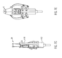
- FIGS. 2 to 9 illustrate a second embodiment of a device according to the invention, wherein in FIG. 2 some parts of the device are omitted, so that FIG. 2 merely illustrates the path of a already simply folded web marked with reference numeral 10.
- FIG. 2 discloses a Tütenabsch disturb worn marked with reference numeral 100, which includes a toothed anvil 110, on the periphery of a plurality of projections 112 are arranged, which are connected via a common foot 114 with the otherwise cylindrical outer periphery of the anvil 110.
- the front side of the projections 112 have a plan view of an envelope surface around all protrusions 112 corresponding geometric configuration.
- the end face of the projections 112 can just as well be more convexly curved than this envelope surface.
- the concrete contour of the end face of the projections 112 depends on the material properties of the flat web 2 forming the web 10 and on parameters of a sonotrode designated by reference numeral 116.
- the underside closed web 10 is deflected via a Umlenkabrolle and supplied to the anvil wheel 110 so that the web 10 is applied substantially tangentially to the end face of the projections 112.
- gripping devices still to be described below access the track 10 and pull it in the direction of rotation of the anvil wheel 110.
- the web 10 extends in the region of the sonotrode 116 substantially in a straight line between the end faces of the projections 112, wherein said gripping device lies radially within an imaginary envelope surface around the projections 112 and accordingly does not collide with the sonotrode 116.
- the protrusions 112 have a greater height than the underside closed web 10. Accordingly, the web 10 protruding lengths of the protrusions 112 above and below the web 10 can be seen.
- the sonotrode 116 has a sonotrode head 118, whose length in the direction of extension of a rotation axis 122 of the rim gear 110 substantially corresponds to the length of the projections 112 in this direction.
- the sonotrode head 118 has a substantially rectangular active surface, which can be arranged opposite the front side of the projections 112. However, this active surface is arranged obliquely relative to the end face of the projections 112, so that the active surface of the sonotrode 116 at no time covers the entire counter surface formed by the projections 112. Accordingly, the vibration caused by the sonotrode 116 acts only on a small length of the path 10 provided between the sonotrode 116 and the associated projection 112, the length extending in the direction of the axis of rotation 122.
- the smallest distance between the sonotrode head 118 and the end face of the projection 112 is dimensioned so that the double-lying material of the web 10 is severed by the oscillating head of the sonotrode 116, whereas adjacent thereto, arranged between the end face of the projections 112 and the sonotrode 116 surface areas of Web 110 are sealed by welding, without a significant weakening of the material of the web 10 occurs. Accordingly, after passing through the sonotrode 116 at the level of the projections 116, the web 10 closed by folding on the underside each has a separating seam 124 through which the web 10 is separated into longitudinal sections corresponding to the width of the bags to be formed, as well as transverse welds arranged on either side of the separating seam 124 126.
- the cutting seam 124 can thereby be formed so that only a certain, acting on the separating seam 124 tensile force the individual lengths of the sections formed by the Querabsch professionungen 126, only still unclosed bags 30 are actually separated from each other.
- the bags 30 thus formed continue to be guided substantially on the outer periphery of the anvil wheel 110.
- the individual bags 30 are pivoted about their central longitudinal axis until the initially tangential between the end faces of individual projections 112 extending fold 8 is arranged radially to the axis of rotation 122 of the anvil wheel 110 (see. FIG. 2 , in the direction of rotation of the anvil wheel 110 last bag 30).
- FIG. 3 shows a perspective top view of the in FIG. 2 shown front peripheral portion of the anvil wheel 110, wherein in addition to the in FIG. 2 a circular metering plate 200 indicated by reference numeral 200 is shown, which has a plurality of filling tubes 210 in the circumferential direction, whose pitch substantially corresponds to the pitch of the anvil wheel 110 and which project from a feed side 220 of the metering plate 200.
- Upper task page 225 the metering plate 100 leading to the filling tubes 210, flush with the task side 225 of the there level metering plate 200 opening funnel openings 230, which are arranged with a small circumferential distance relative to each other.
- the filling tubes 210 are chamfered at their free end and accordingly formed to taper to a point.
- an axis of rotation of the metering plate 200 indicated by reference numeral 240 is set at an angle relative to the axis of rotation 122 of the anvil wheel 110.
- the axis of rotation 122 of the anvil wheel 110 or the axis of rotation 240 of the metering plate 200 may extend in the vertical direction.
- the dosing plate 200 is only inclined relative to the vertical with its axis of rotation 240 in such a way that contents deposited on the feed side 225 do not slip.
- the filling tubes 210 dive into the bags 30 only over a certain peripheral portion relative to the circumference of the anvil wheel 110.
- the relative movement between the filling tubes 210 and the bags 30 in this preferably strictly vertical direction is solely dependent on the degree of inclination between the two axes 120, 240.
- a conveyor belt 242 On the task side 225 of the dosing plate 200 is a designated by reference numeral 250 weighing device ( FIG. 4 ) with a conveyor belt 242, which is arranged with its feed end below a metering device 260, namely under an outlet tube 262 of the metering device 260, which comprises a driven screw 264 which projects into a metering funnel 266 and into the outlet tube 262.
- the end of the conveyor belt 252 opposite the feed end ejects a material continuously fed onto the conveyor belt 252 onto the surface of the metering plate 200, between the hopper openings 230 and a sliding element 268 stationarily associated with the weighing device 250 and its effective sliding surface from the weighing device 250 is arranged radially outward and finally ends at the level of the funnel openings 230.
- the drive of the worm 264 and the output of the weighing device 250 are connected to each other via a control device, not shown.
- the weighing device 250 measures the weight of the material deposited on the weighing device 250, which may vary even with ideal volumetric dosing due to sedimentation. As a result of this variation, the weighing device 250 measures changing masses of the Gutstranges deposited on the conveyor belt 252.
- This weight signal is evaluated by the controller and causes a change in the rotational speed of the screw 264 by acting on the associated in the screw 264 drive motor with the aim that a predetermined length of the deposited on the feed side 225 of the metering plate 200 Massestranges has a constant mass weight. In particular, it is of interest that the strand of material which is discharged into a funnel opening 230 in each case. The aim is to achieve a substantially constant weight-filling of the individual bags 30 despite sedimentation and different density of the bulk material.
- FIG. 5 shows a representation substantially corresponding to the FIG. 3 for another peripheral portion of the anvil wheel 110 and illustrates a designated by reference numeral 300 welding means for closing the bag.
- This welding device has a fixed anvil 310, which is arranged between the bag 30 to be closed of the projections 112 enveloping cylindrical surface.
- a rotating sonotrode 320 On the opposite side of the stationary anvil 310 is a rotating sonotrode 320, which can be driven at the speed with which the bags 30 are guided past the welding device 300.
- FIG. 6 lets recognize the components of the embodiment described above.
- a gripper arrangement indicated by reference numeral 400 is shown, which is provided substantially on the underside of the anvil wheel 110 facing away from the dosing plate 200.
- This gripper assembly 400 has a plurality of gripping means 410 substantially rotating on a circular path, the essential components of which are in the FIGS. 7A to G and 8th can be seen.
- each gripping device 410 is supported by a gripper base indicated by reference numeral 412, which supports pivotally driven gripper arm pairs 414.
- a folding arm 418 is arranged, the free end of which projects beyond the gripper base 412 and is provided with hammer-head-like folding projections 420.
- the folding arms 418 are curved in the front area like a prong to each other and close in the in FIG. 7 characterized position flat jaws 422 of the gripping device 410, which are pivotally mounted about an axis parallel to the fold 8 extending axis, ie about an axis which extends substantially in the horizontal, said pivot axis of the jaws 422 by a Fork carrier 426 is pivotable about an axis perpendicular thereto, which extends vertically.
- the fork carriage 426 is mounted to pivot and driven on the gripper base 412.
- the pivoting movement of the fork carrier 426 and the pivotal movement of the clamping jaws 422 can be positively controlled by scenes, which, depending on the angle of rotation of the gripping device 410 with respect to the center of rotation M ( FIG. 8 ) cause the necessary movements of the gripping device 410.
- FIG. 8 shows a plan view of the bottom of the previously discussed embodiment, wherein the gripper assembly 400 is disposed upstream of the anvil 110.
- the anvil wheel 110 and the gripper assembly 400 rotate about the common center M.
- the gripper assembly 400 for each gripper device 410 additionally has a longitudinal guide over which each individual gripping device 410 is translationally movable in the radial direction.
- Gripper carrier 426 are schematically drawn, which are mounted displaceably in the radial direction on spokes 428 of the gripper assembly 400. Recognizable are different radial positions of the gripper carrier 426 relative to the center of rotation M.
- the deflected path 10 is thereby moved between the open clamping jaws 422, which close at position B by pivoting and clamp the fold 8 of the track 10 closed on the underside.
- the fork carriage 424 continues to have a pivot angle of 0 °, ie is in the starting position.
- the fork carriage 424 is pivoted, during which the filling tubes 210 dive into the bags 30 (see. FIG. 6 ).
- the folding arms 418 remain in their in the FIGS. 7A and 7B marked starting position.
- position D (cf. FIG. 8 )
- the bag 30 has been pivoted by 90 °, so that the initially tangentially relative to the anvil 110 extending fold 8 is now radially aligned with the center M (see. Figure 7D ).
- the pivoting movement of the fork carriage 424 has thus come to an end. It begins the pivoting movement of Greiferarmcrue 414, ie the folding arms 418 (see. Figure 7E ).
- the folding arms 418 rest against the transverse welds 126 of the bags 30 and slide in the direction of the open end of the bag 30.
- the bag 30 is folded over.
- the initially opposite longitudinal sides of the web 10 are kinked in the middle (kink K -. FIGS. 7D to F ).
- To this kink K pivoting of the upper edge portions of the bag 30 is carried out until the Querabsch bulkung 126 centrally containing longitudinal sections opposite to the bag mouth (see. FIG. 7F ).
- FIG. 9 shows in the left position of this top-side closing of the bag 30 and thus the production of the tea bag 40.
- the folding arms 418 have moved down again.
- the folding arms 418 have already been pivoted back to their starting position.
- the finished tea bags 40 are discharged in the radial direction, for example, by an air pressure shock, which is ejected by a arranged between the tea bag 40 and the anvil 110 air nozzle.
- the jaws 422 pivoted back to the starting position and opened.
- the folding arms 418 are then pivoted back to their original position.
- the fork carriage 424 is pivoted back to its original position, in which the pivot axis of the jaws 422 extends substantially tangentially in the center M.
- the pivot axis of the jaws 422 extends substantially tangentially in the center M.
Abstract
Description
Die vorliegende Erfindung betrifft ein Verfahren und eine Vorrichtung zum Herstellen von Beuteln, insbesondere zur Herstellung von Aufgussbeuteln.The present invention relates to a method and an apparatus for producing bags, in particular for the production of infusion bags.
Die vorliegende Erfindung geht insbesondere von einem Verfahren aus, wie es aus der
Bei dem gattungsgemäßen Verfahren werden auch die allseits verschlossenen Beutel weiterhin als Teil einer Endlosbahn gefördert. Durch Umorientieren der Bahn werden die Beutel mit ihrer Seitenfläche auf einer Ablagebahn abgelegt, um schließlich ebenfalls als Kontinuum einer Schneidvorrichtung zugeführt zu werden. Diese Schneidvorrichtung umfasst ein rotierendes Messer, welches von oben gegen die Ablagebahn derart einwirkt, dass die Folienbahn im Bereich einer die hintereinander liegenden Kammern abteilenden Naht getrennt wird. Durch dieses Trennen werden Beutel unabhängig von der Bahn zur Verfügung gestellt. Die separaten Beutel fallen auf eine Förderstrecke ab, von wo sie aus der Vorrichtung ausgefördert werden.In the generic method, the bags, which are sealed on all sides, continue to be conveyed as part of a continuous web. By reorienting the web, the bags are deposited with their side surface on a storage path, to finally also fed as a continuum of a cutting device. This cutting device comprises a rotating knife, which acts from above against the storage path such that the film web is separated in the region of a section dividing the successive chambers seam. This separation makes bags available regardless of the lane. The separate bags fall on a conveyor line, from where they are discharged from the device.
Das vorbekannte Verfahren ist relativ aufwändig, da erheblich Förderstrecken benötigt werden um die einzelnen Verfahrensschritte an hierfür geeigneten Stationen durchzuführen.The previously known method is relatively complicated, since conveyor lines are required in order to carry out the individual method steps at stations suitable for this purpose.
Ein ebenfalls gattungsgemäßes Verfahren ist aus der
Der vorliegenden Erfindung liegt das Problem zugrunde, ein verbessertes Verfahren und eine Vorrichtung zum Herstellen von Beuteln anzugeben, welches sich insbesondere platzsparender und damit einfacher durchführen lässt. Dabei hat die vorliegende Erfindung insbesondere die Herstellung von Aufgussbeuteln, d.h. Beuteln enthaltend aufgussfähiges Material im Blick. Im Besonderen will die vorliegende Erfindung ein Verfahren und eine Vorrichtung zur Herstellung von Aufgussbeuteln in Tetraederform angeben, wie sie beispielsweise in der
Zur Lösung des verfahrensmäßigen Problems wird mit der vorliegenden Erfindung ein Verfahren mit dem Merkmal von Anspruch 1 vorgeschlagen. Dieses unterscheidet sich dadurch von dem gattungsgemäßen Verfahren, dass eine Trennnaht zwischen benachbarten Kammern ausgebildet wird, durch die die einzelnen Beutel von der Flachbahn getrennt werden, und die Kammern nach dem Ausbilden der Trennnaht mit dem Gut gefüllt werden. Bei dem erfindungsgemäßen Verfahren wird dementsprechend zunächst eine Trennnaht ausgebildet, über welche ein Trennen der Beutel erfolgt. Im Gegensatz zum Stand der Technik ist das durch die Flachbahn gebildete Kontinuum bereits vor dem Befüllen der Kammern derart unterbrochen, dass die einzelnen Beutel ohne einen schneidend bzw. trennend auf das Material der Flachbahn einwirkenden gesonderten Verfahrensschritt vereinzelt werden können. Beim Vereinzeln wird der Seitenabstand der zunächst als Kontinuum geführten Kammern vergrößert, d. h. die Kammern grenzen nicht mehr unmittelbar aneinander mit sich im Wesentlichen berührenden Seitenrändern.To solve the procedural problem, the present invention proposes a method having the feature of claim 1. This differs from the generic method that a separating seam is formed between adjacent chambers, through which the individual bags are separated from the flat web, and the chambers are filled after forming the cutting seam with the good. Accordingly, in the method according to the invention, a separating seam is initially formed, via which the bags are separated. In contrast to the prior art, the continuum formed by the flat track is interrupted before the chambers are filled such that the individual bags can be separated without a separate method step acting on the material of the flat web without cutting or separating. When singling, the lateral distance of the chambers, initially run as a continuum, is increased; H. the chambers no longer directly adjoin one another with substantially touching side edges.
Dabei wird ein Verfahren mit den Merkmalen von Anspruch 1 auch dann verwirklicht, wenn nach dem Ausbilden der Trennnaht die dann gebildeten Kammern nach Art eines Kontinuums, d. h. mit Wesentlichen angrenzenden Seitenflächen geführt werden. Wesentlich ist lediglich der Umstand, dass nach dem Befüllen kein Trennvorgang zu erfolgen hat, sondern die die einzelnen Beutel ausbildenden Kammern vor oder nach bzw. während des Verschließens der der Falte gegenüberliegenden Seite durch eine Relativbewegung, bei der gegebenenfalls die Kammern auch durch Abreißen im Bereich der Trennnaht voneinander getrennt werden.In this case, a method having the features of claim 1 is also realized if, after the formation of the separating seam, the chambers then formed are guided in the manner of a continuum, ie with substantially adjacent side surfaces. It is essential only the fact that after filling no separation process has to take place, but the chambers forming the individual bags before or after or during the closing of the opposite side of the fold by a relative movement, in which, if appropriate, the chambers are separated from one another by tearing off in the region of the separating seam.
So wird gemäß einer bevorzugten Weiterbildung der vorliegenden Erfindung vorgeschlagen, das die Beutel bildende Material zumindest von dem Bilden der Falte bis zum Verschließen an der der Falte gegenüberliegenden Seite kontinuierlich zu bewegen. Diese kontinuierliche Bewegung ist bei dem erfindungsgemäßen Verfahren vorzugsweise eine Bewegung um einen Drehpunkt. Dabei können gewisse Bewegungsanteile auch in radialer Richtung erfolgen, so dass die Bewegung des Materials nur annähernd eine kreisförmige Bewegung ist. Insbesondere kann im Rahmen der Bewegung um einen Drehpunkt der Radialabstand ausgehend von einem Einlaufbereich, bei dem die einseitig mit einer Falte verschlossene Bahn der Bearbeitungsstrecke zum Ausbilden von Kammern zugeführt wird, hin zu einer Station, bei welcher das Material auf der der Falte gegenüberliegenden Seite zur Ausbildung eines geschlossenen Beutels verschlossen wird, leicht vergrößert werden. Damit ist die Möglichkeit geschaffen, zwischen einem die Bahn führenden Vortriebsrad und dem Bahnmaterial einen Amboss einer Schweißeinrichtung vorzusehen, die beim Verschließen der der Falte gegenüberliegenden Seite wirksam ist.Thus, according to a preferred development of the present invention, it is proposed to continuously move the material constituting the pouches at least from the formation of the fold to closing at the side opposite the fold. In the method according to the invention, this continuous movement is preferably a movement about a pivot point. In this case, certain components of motion can also take place in the radial direction, so that the movement of the material is only approximately a circular movement. In particular, in the context of the movement about a pivot point of the radial distance starting from an inlet region in which the unilaterally closed with a fold path of the processing path for forming chambers, to a station, wherein the material on the opposite side of the fold to Formation of a closed bag is closed, easily enlarged. Thus, the possibility is provided to provide an anvil of a welding device between a path leading the driving wheel and the web material, which is effective in closing the opposite side of the fold.
Gemäß einer bevorzugten Weiterbildung der vorliegenden Erfindung wird das die Beuteln bildende Material vor dem Ausbilden der Trennnaht bis hin zum Verschließen an der der Falte gegenüberliegenden Seite von einer einem einzelnen Beutel zugeordneten Greifeinrichtung gegriffen und gefördert, bis der Beutel durch Verschließen auf der der Falte gegenüberliegenden Seite hergestellt ist. Dabei sind üblicherweise mehrere Greifeinrichtungen simultan im Eingriff, wobei jede der Greifeinrichtungen einem einzelnen Beutel, d. h. einem einzelnen Längenabschnitt entsprechend einer Beutellänge der zu fördernden Bahn zugeordnet ist. Mit anderen Worten greifen mehrere Greifeinrichtungen jeweils zwischen die einzelne Kammern jeweils abteilende Abteilungen, die regelmäßig durch Querschweißnähte gebildet sind. Die Greifeinrichtung wird dabei üblicherweise vor dem Ausbilden der Kammern wirksam, d. h. greift die Falte vor dem Ausbilden der Kammer. Das Lösen dieses Eingriffs erfolgt üblicherweise unmittelbar nach dem Verschließen der fertig gestellten Beutel. Das Greifen durch die Greifeinrichtungen erfolgt weiterhin vorzugsweise dadurch, dass die Greifeinrichtung jeweils das Material der Bahn lediglich im Bereich der Falte greift, ansonsten aber das oberhalb der Falte und üblicherweise zwischen den Kammerteilungen vorgesehene Volumen unbeeinträchtigt lässt. Mit anderen Worten kann die Kammer trotz eingreifender Greifeinrichtung bis zu oder nahezu bis zu dem durch die Falte gebildeten Boden gefüllt werden.According to a preferred embodiment of the present invention, the bag-forming material is gripped and conveyed by a gripper device associated with a single bag prior to forming the cut seam to closing on the opposite side of the pleat until the bag closes on the opposite side of the pleat is made. In this case, usually more gripping means are simultaneously engaged, each of the gripping means being associated with a single bag, ie a single length corresponding to a bag length of the web to be conveyed. In other words, a plurality of gripping devices each engage between the individual compartments dividing departments, which are regularly formed by transverse welds. The gripping device is usually effective before forming the chambers, ie engages the fold before forming the chamber. The release of this intervention is usually carried out immediately after closing the finished bag. The gripping by the gripping devices is further preferably carried out in that the gripping device engages the material of the web only in the region of the fold, but otherwise leaves the volume provided above the fold and usually between the chamber distributions unimpaired. In other words, can the chamber despite engaging gripping device are filled up to or almost to the bottom formed by the fold.
Gemäß einer bevorzugten Weiterbildung der vorliegenden Erfindung werden einseitig offene Tüten vereinzelt. Einseitig offene Tüten sind an drei üblicherweise sich rechtwinklig zueinander erstreckenden Seiten miteinander verbundene Abschnitte der doppellagigen Bahn, die einerseits durch die Falte und an ihren sich rechtwinklig hierzu erstreckenden Enden durch die Abteilung, d. h. Querschweißnähte verschlossen sind. Die Tüten sind getrennt. Diese Tüten werden befüllt, vorzugsweise während des Vereinzelns. Diese bevorzugte Weiterbildung bietet die Möglichkeit einer effektiven Kammerfüllung, da eine Wechselwirkung benachbarter Kammern beim Befüllen nicht mehr gegeben ist.According to a preferred embodiment of the present invention unilaterally open bags are isolated. On one side open bags are at three usually perpendicular to each other extending sides interconnected portions of the double-layered web, on the one hand by the fold and at their perpendicular thereto extending ends through the department, d. H. Transverse welds are closed. The bags are separated. These bags are filled, preferably during singulation. This preferred development offers the possibility of an effective chamber filling, since an interaction of adjacent chambers during filling is no longer present.
Mit Blick auf die Herstellung von Tetraederbeuteln wird gemäß einer bevorzugten Weiterbildung der vorliegenden Erfindung vorgeschlagen, die einseitig offenen Tüten an der der Falte gegenüberliegenden Seite mit einer Schweißnaht zu verschließen, die sich im Wesentlichen rechtwinklig zu der Falte erstreckt. Dementsprechend werden vereinzelte, d. h. mit ihren Rändern nicht mehr aneinander stoßende Tüten verschweißt, und zwar über eine Schweißnaht, die sich im Wesentlichen rechtwinklig zu der Falte erstreckt, wodurch ein Tetraederbeutel gebildet ist.With a view to the production of tetrahedral bags according to a preferred embodiment of the present invention, it is proposed to close the unilaterally open bags on the opposite side of the fold with a weld which extends substantially perpendicular to the fold. Accordingly, scattered, d. H. welded with their edges no longer abutting bags, via a weld, which extends substantially perpendicular to the fold, whereby a tetrahedral bag is formed.
Hierzu werden gemäß einer weiteren bevorzugten Ausgestaltung der vorliegenden Erfindung die einseitig offenen Tüten vor dem Verschließen so verschwenkt, dass die Falte im Wesentlichen rechtwinklig zu der Vortriebsrichtung der Tüte ausgerichtet ist. Bei dieser bevorzugten Weiterbildung werden die Tüten im Grunde um ihre eigene Achse gedreht, während sie gleichzeitig vorzugsweise auf der annähernden Kreisbahn von der Station zum Ausbilden der Kammern bis zum Ausschleusen des fertigen Beutels, d. h. um einen gemeinsamten Drehpunkt verschwenkt werden. Üblicherweise werden die Tüten dabei während des Befüllens um ihre eigene Achse verschwenkt, jedenfalls aber wird während des Verschwenkens in die Tüten ein Füllrohr zum Befüllen der Tüten eingebracht. Durch diese Maßnahme lässt sich die Wegstrecke über die verschiedenen Stationen bis hin zum Ausschleusen des fertigen Beutels und damit die Bearbeitungszeit verringern.For this purpose, according to a further preferred embodiment of the present invention, the unilaterally open bags are pivoted before closing so that the fold is aligned substantially perpendicular to the advancing direction of the bag. In this preferred embodiment, the bags are basically rotated about their own axis, while at the same time preferably on the approximate circular path from the station to form the chambers to the discharge of the finished bag, d. H. to be pivoted about a common pivot point. Usually, the bags are thereby pivoted about their own axis during filling, but anyway, a filling tube for filling the bags is introduced during the pivoting in the bags. By this measure, the distance over the various stations to the discharge of the finished bag and thus reduce the processing time.
Zur Lösung des vorrichtungsmäßigen Aspektes wird mit der vorliegenden Erfindung eine Vorrichtung mit dem Merkmal von Anspruch 8 vorgeschlagen. Diese Vorrichtung hat eine Falteinrichtung zum Falten einer Flachbahn, wie sie beispielsweise für sich aus der
Weiterhin hat die erfindungsgemäße Vorrichtung einen rotierenden Dosierteller mit einer Aufgabeseite zum Aufbringen des Beutelinhalts und einer gegenüberliegenden Beschickungsseite, von der eine Vielzahl von Füllrohren abragt, die in die Kammern eindringbar sind. Folglich wird in jede der Kammern jeweils ein Füllrohr eingebracht. Die Drehachse des Dosiertellers steht dabei schräg zu der Drehachse des Ambossrades, so dass die Füllrohre aufgrund der Schrägstellung über einen gewissen Winkelabschnitt der am Außenumfang des Ambossrades befindlichen Kammern in diese eindringen und zwangsläufig aufgrund der Schrägstellung aus den Kammern herausgezogen werden. Dabei spielt es keine Rolle, ob die Kammern noch im Kontinuum vorgesehen, d. h. mit sich im Wesentlichen berührenden Seitenrändern bewegt werden, oder aber bereits vereinzelt sind, d. h. die jeweiligen Füllrohre in einzelne Tüten eingreifen. Dementsprechend kann der Dosierteller alternativ oder kumulativ auch hinsichtlich seiner Drehachse schräg zu einer Drehachse der Greiferanordnung ausgerichtet sein. Die erfindungsgemäße Vorrichtung hat ferner eine Schweißeinrichtung zum Verschließen der Beutel auf der der Falte gegenüberliegenden Seite sowie eine Ausschleuseinrichtung zum Ausfördern der Beutel. Diese Ausschleuseinrichtung bewegt die Beutel regelmäßig in Radialrichtung relativ zu der Drehrichtung des Ambossrades und/oder der Greiferanordnung. Das Ausschleusen kann beispielsweise mittels Luftdruck oder eines Mitnehmers erfolgen, der beispielsweise in Radialrichtung und/oder rechtwinklig zu der Drehachse des Ambossrades bewegt wird.Furthermore, the device according to the invention has a rotating metering plate with a feed side for applying the bag contents and an opposite feed side from which protrudes a plurality of filling tubes, which are penetratable into the chambers. Consequently, a filling tube is introduced into each of the chambers. The axis of rotation of the metering plate is inclined to the axis of rotation of the anvil wheel, so that the filling tubes penetrate due to the inclination over a certain angle section located on the outer circumference of the anvil wheel chambers in this and inevitably be pulled out of the chambers due to the inclination. It does not matter whether the chambers are still provided in the continuum, ie moved with substantially touching side edges, or are already isolated, ie the respective filling tubes engage in individual bags. Accordingly, the metering plate may alternatively or cumulatively also be aligned with respect to its axis of rotation obliquely to a rotational axis of the gripper assembly. The device according to the invention also has a welding device for closing the bags on the side opposite the fold and a discharge device for conveying out the bags. This ejector moves the bags regularly in the radial direction relative to the direction of rotation of the anvil wheel and / or the gripper assembly. The discharging can be done for example by means of air pressure or a driver, which is moved for example in the radial direction and / or perpendicular to the axis of rotation of the anvil wheel.
Gemäß einer bevorzugten Weiterbildung der vorliegenden Erfindung ist die Sonotrode ortsfest und schräg zu den Ambossvorsprüngen ausgerichtet. Dabei hat die Sonotrode eine wirksame Länge, die zumindest die Breite der gefalteten Bahn überstreicht. Regelmäßig sind die Zahnvorsprünge des Ambossrades so ausgebildet, dass diese die gefaltete Bahn quer zu ihrer Längsrichtung, d. h. in Breitenrichtung beidseitig überragen. Die Sonotrode und das Ambossrad sind dabei so aufeinander abgestimmt, dass im Rahmen einer Annäherung der Stirnseite der Zahnvorsprünge an die Sonotrode zunächst eine Querschweißnaht ausgebildet wird, bei minimalem Abstand indes das Material der Bahn zwischen der Sonotrode und der Stirnseite des Zahnvorsprunges mit einer Trennnaht versehen wird und im Zuge der weiteren Verschwenkbewegung, d. h. mit sich vergrößerndem Radialspalt erneut unmittelbar neben der Trennnaht eine Querschweißnaht ausgeformt wird. Die Trennnaht durchsetzt danach zwei nebeneinander vorgesehene, Kammern begrenzende Querschweißnähte. Die Schrägstellung der Sonotrode relativ zu der im Wesentlichen axialen Erstreckung der Zahnvorsprünge bewirkt dabei eine schonende Behandlung des zugeführten Materials. Das Ausbilden der Trennnaht erfolgt lediglich unter der lokalen Erwärmung in Längsrichtung. Mit Zunehmen der Verschwenkbewegung wandert dieser Punkt in axialer Richtung, so dass ein Ausbilden der Trennnaht nicht in Einem über die gesamte Breite der Bahn erfolgt, sondern die zum Ausbilden der Trennnaht in das Bahnmaterial eingebrachte Reibungswärme in axialer Richtung von einem Ende des Bahnmaterials in Breitenrichtung zu dem anderen wandert.According to a preferred embodiment of the present invention, the sonotrode is stationary and aligned obliquely to the anvil protrusions. The sonotrode has an effective length that at least covers the width of the folded web. Regularly, the tooth projections of the anvil wheel are formed so that they the folded web transversely to its longitudinal direction, d. H. tower on both sides in the width direction. The sonotrode and the anvil are matched to one another such that initially a transverse weld seam is formed as the end face of the tooth projections on the sonotrode approaches, while the material of the web between the sonotrode and the end face of the tooth projection is provided with a separating seam at a minimum distance and in the course of the further pivoting movement, d. H. With increasing radial gap again immediately adjacent to the cutting seam a transverse weld is formed. The dividing seam then passes through two adjacently provided transverse weld seams delimiting the chambers. The inclination of the sonotrode relative to the substantially axial extent of the tooth projections causes a gentle treatment of the supplied material. The formation of the cutting seam is carried out only under the local heating in the longitudinal direction. As the pivoting movement increases, this point migrates in an axial direction such that the forming of the parting line does not occur in one over the entire width of the web, but the frictional heat in the axial direction introduced from one end of the web material in the direction of the width to form the parting line in the web material the other one wanders.
Gemäß einer bevorzugten Weiterbildung der vorliegenden Erfindung weist die Schweißeinrichtung zum Verschließen der Beutel einen ortsfesten Amboss auf, der zwischen dem Ambossrad und einer Sonotrode angeordnet ist. Bei der Sonotrode handelt es sich insbesondere um eine rotierende Sonotrode, deren Außenumfangsfläche mit dem Amboss zusammenwirkt.According to a preferred development of the present invention, the sealing device for closing the bags has a fixed anvil which is arranged between the anvil wheel and a sonotrode. The sonotrode is, in particular, a rotating sonotrode whose outer peripheral surface interacts with the anvil.
Gemäß einer bevorzugten Weiterbildung ist die Greifeinrichtung schwenkbar auf einer Greiferbasis gelagert, die zumindest zwei auf das offene Ende der Tüte einwirkende Faltarme verschwenkbar lagert. Die Faltarme sind dabei üblicherweise über einen Viergelenksmechanismus gelagert und bevorzugt so betrieben, dass diese beidseitig mit dem offenen Ende der Tüte zusammenwirken und auf dieses einwirken, um einander gegenüberliegende Flächen der Tüte vor dem Verschließen gegeneinander zu legen, bevor der Beutel durch Verschließen an der der Falte gegenüberliegenden Seite hergestellt wird.According to a preferred embodiment, the gripping device is pivotally mounted on a gripper base, which supports at least two folding arms acting on the open end of the bag pivotable. The folding arms are usually mounted on a four-bar linkage mechanism and preferably operated so that they cooperate on both sides with the open end of the bag and act on this to face opposing surfaces of the bag before closing against each other before the bag by closing on the Fold opposite side is made.
Zur Herstellung eines Radialabstandes zwischen dem Ambossrad und den einzelnen Tüten sind die Greifeinrichtungen in der Greiferanordnung radial translatorisch beweglich gelagert. So werden die einzelnen, von den Greifeinrichtungen gehaltenen Tüten nicht nur um den Drehpunkt der Greiferanordnung verschwenkt, sondern gleichzeitig radial translatorisch nach Außen bewegt.To produce a radial distance between the anvil wheel and the individual bags, the gripping devices in the gripper arrangement are mounted so as to be movable in a translatory manner. Thus, the individual, held by the gripping means bags are not only pivoted about the pivot point of the gripper assembly, but simultaneously moved radially translationally to the outside.
Gemäß einer bevorzugten Weiterbildung, die für sich erfindungswesentlich sein kann, ist auf der Aufgabeseite des Dosiertellers eine Dosiereinrichtung und eine Wägeeinrichtung angeordnet. Die Dosieranordnung gibt einen Massestrom in Richtung auf die Aufgabeseite ab, der zunächst auf die Wägeeinrichtung trifft und dort erfasst wird. Die Wägeeinrichtung und die Dosiereinrichtung sind über eine Steuerung steuerungsmäßig verbunden, die einen von der Wägeeinrichtung erfassten Ist-Wert des Massestroms mit einem Sollwert vergleicht und aufgrund dieses Vergleiches den von der Dosiereinrichtung abgegebenen Massestrom steuert. Durch diese Regelstrecke wird sichergestellt, dass im Wesentlichen ein konstanter Massestrom auf die Aufgabeseite des Dosiertellers abgelegt wird. Dabei erfolgt das Ablegen des Massestroms üblicherweise in Form eines Gutstreifens, der auf dem Dosierteller auf der radial inneren Seite relativ zu einer Mündung der Füllrohre vorgesehen ist. Der Aufgabeseite des Dosiertellers zugeordnet ist üblicherweise ein Abstreifer vorgesehen, der ortsfest und relativ beweglich zu dem rotierenden Dosierteller montiert ist und welcher das auf die Beschickungsseite abgelegte und drehend bewegte Gut radial nach Außen und in die Mündungen zu den Füllrohren ausschiebt.According to a preferred embodiment, which may be essential to the invention, a metering device and a weighing device is arranged on the task side of the metering plate. The metering arrangement emits a mass flow in the direction of the feed side, which initially strikes the weighing device and is detected there. The weighing device and the metering device are connected in terms of control via a controller which compares an actual value of the mass flow detected by the weighing device with a desired value and controls the mass flow delivered by the metering device on the basis of this comparison. This controlled system ensures that essentially a constant mass flow is deposited on the feed side of the metering plate. The removal of the mass flow is usually carried out in the form of a Gutstreifens, which is provided on the metering plate on the radially inner side relative to an opening of the filling tubes. Assigned to the task side of the metering plate is usually provided a scraper, which is fixedly mounted and relatively movable to the rotating metering plate and which pushes out the deposited on the feed side and rotationally moving material radially outwards and into the mouths to the filling tubes.
Die bevorzuge Weiterbildung mit einer Regelstrecke zwischen der Dosiereinrichtung und der Wägeeinrichtung bietet die Möglichkeit, insbesondere bei aufgussfähigem Material, speziell Tee zu sehende Effekte zu kompensieren, die durch Entmsichung begründet sind. Bei einem konstanten Volumenstrom von zugefördertem aufgussfähigem Material führt diese Entmsichung zu einem höheren Massestrom eines anfänglichen, unteren Inhalts der Dosiereinrichtung im Vergleich zum Ausfördern des oben liegenden Inhalts, da sich aufgrund der Entmsichung die Dichte in Füllhöhe ändert und im unteren Teil eines Fördertrichters oder -turms Schüttgut mit einer hörere Dichte vorhanden ist als im oberen Teil. Mithin können durch die Regelstrecke in der Natur des Gutes begründete Variationen der Schüttdichte kompensiert werden.The preferred development with a controlled system between the metering device and the weighing device offers the possibility, in particular in the case of pourable material, of compensating specifically for tea effects that are due to dehydration. At a constant volumetric flow rate of infused infusible material, this desiccation results in a higher mass flow of an initial, lower contents of the metering device as compared to discharging the overhead contents, because the density changes in filling height due to desiccation and in the lower part of a conveying hopper or tower Bulk material with a higher density is present than in the upper part. Consequently, justified variations in the bulk density can be compensated by the controlled system in the nature of the goods.
Weitere Einzelheiten und Vorteile der vorliegenden Erfindung ergeben sich aus der nachfolgenden Beschreibung von zwei Ausführungsbeispielen in Verbindung mit der Zeichnung. In dieser zeigen:
- Figur 1
- eine schematische Darstellung wesentlicher Stationen eines ersten Ausführungsbeispiels der vorliegenden Erfindung;
- Figur 2
- eine perspektivische Darstellung eines Ambossrades mit zugeordneter Sonotrode zum Abschweißen von Tüten eines zweiten Ausführungsbeispiels;
- Figur 3
- eine perspektivische Darstellung des zweiten Ausführungsbeispiels ähnlich
Figur 2 mit einem Dosierteller; - Figur 4
- der in
Figur 3 gezeigte Dosierteller in einer Draufsicht mit Teilen einer Dosiervorrichtung; - Figur 5
- eine Darstellung des zweiten Ausführungsbeispiels ähnlich zu
Figur 3 für einen anderen Umfangsabschnitt des Ambossrades mit einer Schweißeinrichtung zum Verschließen der Tüten; Figur 6- eine Darstellung des zweiten Ausführungsbeispiels ähnlich zu
Figur 3 mit einer Greiferanordnung; - Figur 7A
- eine perspektivische Darstellung einer Greifeinrichtung der Greiferanordnung nach
Figur 6 in einer Ausgangstellung; - Figur 7B
- eine perspektivische Darstellung der Greifeinrichtung nach
Figur 7A in einer klemmenden Stellung; - Figur 7C
- eine perspektivische Darstellung der Greifeinrichtung nach
Figur 7A in einer die Tüte um eine im Wesentlichen horizontale Achse schwenkenden Stellung; - Figur 7D
- eine perspektivische Darstellung der Greifeinrichtung nach
Figur 7A kurz vor Beendigung der Schwenkbewegung um eine im Wesentlichen horizontale Achse; - Figur 7E
- eine perspektivische Darstellung der Greifeinrichtung nach
Figur 7A nach Beendigung der Schwenkbewegung um eine im Wesentlichen horizontale Achse und zu Beginn des Umfaltens der Tüte; - Figur 7F
- eine perspektivische Darstellung der Greifeinrichtung nach
Figur 7A beim Umfalten der Tüte; - Figur 7G
- eine perspektivische Darstellung der Greifeinrichtung nach
Figur 7A am Ende des Umfaltens; Figur 8- eine Draufsicht auf die Unterseite der in
Figur 6 - Figur 9
- eine vergrößerte perspektivische Darstellung eines Umfangsabschnittes des Ambossrades des zweiten Ausführungsbeispiels mit den verschlossenen Beuteln.
- FIG. 1
- a schematic representation of essential stations of a first embodiment of the present invention;
- FIG. 2
- a perspective view of an anvil wheel with associated sonotrode for welding off bags of a second embodiment;
- FIG. 3
- a perspective view of the second embodiment similar
FIG. 2 with a dosing plate; - FIG. 4
- the in
FIG. 3 dosing plate shown in a plan view with parts of a dosing device; - FIG. 5
- a representation of the second embodiment similar to
FIG. 3 for another peripheral portion of the anvil wheel with a welding device for closing the bags; - FIG. 6
- a representation of the second embodiment similar to
FIG. 3 with a gripper assembly; - FIG. 7A
- a perspective view of a gripping device of the gripper assembly according to
FIG. 6 in a starting position; - FIG. 7B
- a perspective view of the gripping device after
FIG. 7A in a pinching position; - FIG. 7C
- a perspective view of the gripping device after
FIG. 7A in a position pivoting the bag about a substantially horizontal axis; - Figure 7D
- a perspective view of the gripping device after
FIG. 7A shortly before the end of the pivotal movement about a substantially horizontal axis; - Figure 7E
- a perspective view of the gripping device after
FIG. 7A upon completion of the pivotal movement about a substantially horizontal axis and at the beginning of refolding of the bag; - FIG. 7F
- a perspective view of the gripping device after
FIG. 7A when folding the bag; - FIG. 7G
- a perspective view of the gripping device after
FIG. 7A at the end of refolding; - FIG. 8
- a top view of the bottom of in
FIG. 6 shown components of the second embodiment; and - FIG. 9
- an enlarged perspective view of a peripheral portion of the anvil wheel of the second embodiment with the sealed bags.
In
Im Anschluss an die rotierende Schweißeinrichtung 14 ist eine Düse 20 vorgesehen, welche pulsartig in die einzelnen nunmehr abgeteilten Kammern einbläst, um diese zu öffnen. Eine Trenneinrichtung 22 vereinzelt nunmehr die oben offenen Tüten 30. Diese Trenneinrichtung 22 kann durch ein von der Unterseite her wirkendes Messer gebildet sein, welches zyklisch auf die Bahn 10 einwirkt, um die einzelnen Tüten 30 abzuteilen. Während diese Beutel bereits mit ihrem vorlaufenden Ende frei geschnitten und mit ihrem hinteren Ende noch an der Bahn befestigt sind, wird das vorlaufende Ende mit einer Greifeinrichtung 24 gegriffen. Diese Greifeinrichtung 24 umfasst zwei umlaufende Bänder 26, an denen in etwa mit dem Querabstand der Querschweißnähte Haltestege 28 befestigt sind, deren Seitenabstand zueinander so bemessen ist, dass sie das doppellagige Material der Bahn zwischen sich klemmen können. In solcher Art vereinzelte und oberseitig offene Tüten 30, die mit ihrem vorlaufenden und hinteren Ende jeweils zwischen den Haltestegen 28 geklemmt sind, taucht nunmehr ein Füllrohr 32 ein. Dieses Füllrohr 32 ist derart in Bezug auf die Tüte 30 bemessen, das nach Freigabe der Tüte 30 durch die Greifeinrichtung 24 die Tüte 30 senkrecht stehend auf einer Bewegungsbahn 34 abgestützt und geführt werden kann.Subsequent to the
Auf der Bewegungsbahn werden die Tüten 30 über das Füllrohr 32 befüllt und dabei vorzugsweise zeitgleich um 90° gedreht, so dass die Falte 8 nunmehr rechtwinklig zu der Bewegungsrichtung steht.On the trajectory, the
Die freien offenen Enden der Tüten 30 werden hernach über eine Kulisse 36 umgeformt, so dass sich die Ränder der Tüten rechtwinklig zu der Kante 8 aneinander legen. In solcher Weise vorbereitet werden diese Ränder nunmehr mit einer Schweißvorrichtung 38 verschweißt. Als Ergebnis wird ein Teebeutel 40 in Tetraederform von der Produktionsstrecke ausgefördert.The free open ends of the
Die
Wie aus
Die Vorsprünge 112 haben eine größere Höhe als die unterseitig geschlossene Bahn 10. Dementsprechend sind die Bahn 10 überragende Längenabschnitte der Vorsprünge 112 oberhalb und unterhalb der Bahn 10 zu erkennen. Die Sonotrode 116 hat einen Sonotrodenkopf 118, dessen Länge in Erstreckungsrichtung einer Drehachse 122 des Ambrossrades 110 im Wesentlichen der Länge der Vorsprünge 112 in dieser Richtung entspricht. Der Sonotrodenkopf 118 hat eine im Wesentlichen rechteckige Wirkfläche, die gegenüber der Stirnseite der Vorsprünge 112 angeordnet werden kann. Allerdings ist diese Wirkfläche relativ zu der Stirnseite der Vorsprünge 112 schräg angeordnet, so dass die Wirkfläche der Sonotrode 116 zu keiner Zeit die gesamte, durch die Vorsprünge 112 gebildete Gegenfläche überdeckt. Dementsprechend wirkt die durch die Sonotrode 116 verursachte Schwingung lediglich auf ein kleines Längenstück der zwischen der Sonotrode 116 und dem zugehörigen Vorsprung 112 vorgesehenen Bahn 10, wobei das Längenstück sich in Richtung der Drehachse 122 erstreckt.The
Der kleinste Abstand zwischen dem Sonotrodenkopf 118 und der Stirnseite des Vorsprungs 112 ist derart bemessen, dass das doppeltliegende Material der Bahn 10 durch den Schwingkopf der Sonotrode 116 durchtrennt wird, wohingegen benachbart dazu, zwischen der Stirnseite der Vorsprünge 112 und der Sonotrode 116 angeordnete Flächenbereiche der Bahn 110 durch Schweißen verschlossen werden, ohne das eine merkliche Schwächung des Materials der Bahn 10 auftritt. Dementsprechend weist die durch Falten unterseitig geschlossene Bahn 10 nach dem Passieren der Sonotrode 116 auf Höhe der Vorsprünge 116 jeweils eine Trennnaht 124 auf, durch welche die Bahn 10 in Längenabschnitte entsprechend der Breite der zu bildenden Beutel getrennt ist, sowie beiderseits der Trennnaht 124 angeordnete Querabschweißungen 126. Die Trennnaht 124 kann dabei so ausgebildet sein, dass erst eine gewisse, auf die Trennnaht 124 wirkende Zugkraft die einzelnen Längenabschnitte der durch die Querabschweißungen 126 ausgebildeten, nur noch oberseitig unverschlossenen Tüten 30 voneinander tatsächlich getrennt sind. Nach dem Passieren der Tütenabschweißeinrichtung 100 werden die so gebildeten Tüten 30 weiterhin im Wesentlichen an dem Außenumfang des Ambossrades 110 geführt. Zusätzlich werden die einzelnen Tüten 30 um ihre Mittellängsachse verschwenkt, bis die sich zunächst tangential zwischen den Stirnseiten einzelner Vorsprünge 112 sich erstreckende Falte 8 radial zu der Drehachse 122 des Ambossrades 110 angeordnet ist (vgl.
Die Füllrohre 210 sind an ihrem freien Ende angeschrägt und dementsprechend spitz zulaufend ausgeformt. Wie
Auf der Aufgabeseite 225 des Dosiertellers 200 befindet sich eine mit Bezugszeichen 250 gekennzeichnete Wägeeinrichtung (
Der Antrieb der Schnecke 264 und das Ausgangssignal der Wägeeinrichtung 250 sind über eine nicht dargestellte Steuereinrichtung miteinander verbunden. Die Wägeeinrichtung 250 misst das Gewicht des auf die Wägeeinrichtung 250 abgelegten Gutes, welches selbst bei idealer volumetrischer Dosierung aufgrund von Sedimentation variieren kann. Als Ergebnis dieser Variation misst die Wägeeinrichtung 250 sich ändernde Massen des auf das Förderband 252 abgelegten Gutstranges. Diese Gewichtssignal wird über die Steuerung ausgewertet und bewirkt eine Veränderung der Drehgeschwindigkeit der Schnecke 264 durch Einwirken auf den in der Schnecke 264 zugeordneten Antriebsmotor mit dem Ziel, dass ein vorgegebener Längenabschnitt des auf die Aufgabeseite 225 des Dosiertellers 200 abgelegten Massestranges ein gleichbleibendes Massegewicht hat. Es interessiert insbesondere derjenige Massestrang, der jeweils in eine Trichteröffnung 230 ausgefördert wird. Ziel ist es, trotz Sedimentation und unterschiedlicher Dichte des Schüttgutes eine im Wesentlichen konstante gewichtsmäßige Befüllung der einzelnen Tüten 30 zu erreichen.The drive of the
Die
Im Folgenden wird die Funktionalität der einzelnen Greifeinrichtungen 410 unter Bezugnahme auf Positionen dargestellt, die in
In der
Mit dieser Ausrichtung passiert die Bahn 10 die Tütenabschweißeinrichtung 100.With this orientation, the
Danach wird der Gabelträger 424 verschwenkt, wobei während dieser Schwenkbewegung die Füllrohre 210 in die Tüten 30 eintauchen (vgl.
Bei fortschreitender Schwenkbewegung der Faltarme 418 werden diese offenen Längenabschnitte der Tütenmündung gegeneinander gepresst, so dass sich ein in etwa mit der Stärke der Falte 8 ausgeformter Anlagebereich 430 ausbildet (vgl.
Danach ergibt sich folgendes Verfahren:This results in the following procedure:
In einer kontinuierlichen Bewegung wird die unterseitlich geschlossene Bahn 10 zunächst tangential an das Ambossrad 110 angelegt. An der Tütenabschweißeinrichtung 110 werden einzelne Kammern durch Querabschweißungen 126 erzeugt. Es ergeben sich unterschiedliche, durch die Trennnaht 124 bereits im Wesentlichen getrennte Tüten 30, die indes noch nicht vereinzelt sind und die als ein Kontinuum erscheinen. Durch Verschwenken der Gabelträger 424 werden die Tüten 30 nunmehr vereinzelt. Die Vereinzelung erfolgt dabei durch eine Überlagerung einer Verschwenkbewegung der Gabelträger 424 bei gleichzeitiger radialer Bewegung der Greiferträger 426 entlang der Speichen 428 nach außen. Hierdurch wird ein gewisser radialer Abstand zwischen den Tüten 30 und der Hüllfläche um die Vorsprünge 112 geschaffen, so dass später die einseitig offenen Tüten an dem radial dem Ambossrad 110 vorgelagerten Amboss 310 vorbeigeführt werden können. Im Rahmen einer kontinuierlichen rotatorischen Bewegung um den Mittelpunkt M werden die Tüten 30 um 90° veschwenkt, so dass die Falte 8 nunmehr eine radiale Ausrichtung einnimmt. Die Tüten 30 werden mit ihren von der Falte 8 abstehenden Wandungsabschnitten, die zunächst parallel zu der Falte 8 ausgerichtet sind, gefaltet, so dass diese parallelen Wandungsabschnitte mit dem mittleren Knick K versehen werden. Danach werden die gegenüberliegenden, mit der Querabschweißung 126 versehenen Seitenwände der Tüte 30 durch weiteres Verschwenken der Faltarme 418 unter Vorspannung gegeneinander angelegt und schließlich im Anlagebereich 430 zur Ausbildung einer weiteren Schweißnaht 432 durch die Schweißeinrichtung 300 verschlossen. Diese weitere Schweißnaht 132 erstreckt sich rechtwinklig zu der Falte 8, so dass ein Tetraeder-Beutel mit vier Seitenflächen, einer unterseitigen Falte und drei rechtwinklig zueinander angeordneten Schweißnähten 432, 126 ausgebildet.In a continuous movement, the
Unter Beibehaltung der Klemmung durch die Klemmbacken 422 werden die Faltarme 418 danach in ihre Ausgangsstellung zurück verschwenkt. Erst danach erfolgt das Ausschleusen der fertigen Teebeutel 40 durch Öffnen der Klemmbacken 422. Nach dieser Station H wird der Gabelträger 424 zurück in seine Ausgangslage verschwenkt, in welcher sich die Schwenkachse der Klemmbacken 422 im Wesentlichen tangential im Mittelpunkt M erstreckt. In dem Winkelsegment zwischen Position 7 C und 7 D gemäß der Darstellung in
- 22
- Flachbahnflat track
- 44
- Vorratsrollesupply roll
- 66
- Faltenbahnfold railway
- 88th
- Faltewrinkle
- 1010
- unterseitig geschlossene Bahnclosed track on the underside
- 1212
- Umlenkrolleidler pulley
- 1414
- rotierende Schweißeinrichtungrotating welding device
- 1616
- Schweißwalzewelding roll
- 1717
- Schweißbackewelding jaw
- 1818
- Schweißwalzewelding roll
- 1919
- Schweißbackewelding jaw
- 2020
- Düsejet
- 2222
- Trenneinrichtungseparator
- 2424
- Greifeinrichtunggripper
- 2626
- Bandtape
- 2828
- Haltestegholding web
- 3030
- Tütebag
- 3232
- Füllrohrfilling pipe
- 3434
- Bewegungsbahntrajectory
- 3636
- Kulissescenery
- 3838
- Schweißvorrichtungwelder
- 4040
- TeebeutelTeabag
- 100100
- TütenabschweißeinrichtungTütenabschweißeinrichtung
- 110110
- Ambossradanvil
- 112112
- Vorsprunghead Start
- 114114
- Fußfoot
- 116116
- Sonotrodesonotrode
- 118118
- Sonotrodenkopfsonotrode
- 122122
- Drehachse des AmbossradesRotary axis of the anvil wheel
- 124124
- Trennnahtseparating seam
- 126126
- QuerabschweißungQuerabschweißung
- 200200
- Dosiertellermetering plate
- 210210
- Füllrohrfilling pipe
- 220220
- Beschickungsseiteloading side
- 225225
- Aufgabeseitetask page
- 230230
- Trichteröffnungfunnel opening
- 240240
- Drehachse des DosiertellersRotary axis of the dosing plate
- 250250
- Wägeeinrichtungweighing
- 252252
- Förderbandconveyor belt
- 260260
- Dosiereinrichtungmetering
- 262262
- Auslassrohroutlet pipe
- 264264
- Schneckeslug
- 266266
- Dosiertrichtermetering funnel
- 268268
- Schiebeelementsliding element
- 300300
- Schweißeinrichtungwelding equipment
- 310310
- Ambossanvil
- 320320
- Sonotrodesonotrode
- 400400
- Greiferanordnunghook assembly
- 410410
- Greifeinrichtunggripper
- 412412
- Greiferbasisgripper base
- 414414
- GreiferarmpaarGreiferarmpaar
- 416416
- Greiferarmgripper
- 418418
- Faltarmfolding arm
- 420420
- FaltarmvorsprungFaltarmvorsprung
- 422422
- Klemmbackejaw
- 424424
- GabelträgerGabelträger
- 426426
- Greiferträgergripper carrier
- 428428
- Speichenspoke
- 430430
- Anlagebereichplant area
- 432432
- weitere Schweißnahtanother weld
- MM
- Mittelpunkt/DrehpunktCenter / pivot point
- KK
- Knickkink
Claims (14)
dadurch gekennzeichnet,
dass eine Trennnaht (24) zwischen benachbarten Kammern ausgebildet wird, durch die die einzelnen Beutel (40) von der Bahn getrennt werden, und dass die Kammern nach dem Ausbilden der Trennnaht (124) mit Gut gefüllt werden.Method for producing bags (40), in particular infusion bags, in which a flat web (2) is folded longitudinally to form a web (10) closed at the bottom by a fold (8), and chambers are provided one behind the other in the longitudinal direction of the web (10) which are filled with material and are carried out by a weld on the opposite side of the fold (8) and separated as separated by separating the web (10) bags,
characterized,
in that a separating seam (24) is formed between adjacent chambers, by which the individual bags (40) are separated from the web, and that the chambers are filled with material after the forming seam (124) has been formed.
einer die gefaltete Bahn (10) greifenden Greiferanordnung (400) mit einer Vielzahl von um einen Drehpunkt (M) bewegten und jeweils schwenkbar gelagerten Greifeinrichtungen (422) zum Klemmen der Falte (8),
einer Tütenabschweißeinrichtung (100) umfassend ein gezahntes Ambossrad (110) und eine mit Vorsprüngen (112) des Ambossrades (110) zusammenwirkende Sonotrode (116) zum Ausbilden von Kammern und einer zwischen den Kammern vorgesehenen Trennnaht (124);
einem rotierenden Dosierteller (200) mit einer Aufgabeseite (225) zum Aufbringen des Gutes und einer gegenüberliegenden Beschickungsseite (210), von der eine Vielzahl von Füllrohre (210) abragt, die in die Kammern einbringbar sind, dessen Drehachse (240) schräg zu der Drehachse (120) des Ambossrades und/oder der Greiferanordnung (400) ausgerichtet ist;
einer Schweißeinrichtung (300) zum Verschließen des Beutels (40) und
einer Ausschleuseinrichtung zum Ausschleusen des Beutels (40).Apparatus for producing bags, in particular infusion bags with a folding device for folding a flat web,
a gripper arrangement (400) which grips the folded web (10) and has a multiplicity of gripping means (422), which are moved about a pivot point (M) and are each pivotally mounted, for clamping the fold (8),
a bag wiper device (100) comprising a toothed anvil wheel (110) and a sonotrode (116) cooperating with projections (112) of the anvil wheel (110) for forming chambers and a separating seam (124) provided between the chambers;
a rotating metering plate (200) having a feed side (225) for applying the goods and an opposite feed side (210) from which a plurality of filling tubes (210) projectable into the chambers, the axis of rotation (240) of which projects obliquely to the Rotary axis (120) of the anvil wheel and / or the gripper assembly (400) is aligned;
a welding device (300) for closing the bag (40) and
a discharge device for discharging the bag (40).
Priority Applications (6)
| Application Number | Priority Date | Filing Date | Title |
|---|---|---|---|
| PT110078102T PT2572996E (en) | 2011-09-26 | 2011-09-26 | Method and device for producing bags |
| EP11007810.2A EP2572996B1 (en) | 2011-09-26 | 2011-09-26 | Method and device for producing bags |
| EP12006642.8A EP2572997B1 (en) | 2011-09-26 | 2011-09-26 | Method and device for producing bags |
| PT120066428T PT2572997E (en) | 2011-09-26 | 2011-09-26 | Method and device for producing bags |
| ES12006642.8T ES2487865T3 (en) | 2011-09-26 | 2011-09-26 | Procedure and device for the manufacture of bags |
| ES11007810.2T ES2516990T3 (en) | 2011-09-26 | 2011-09-26 | Procedure and device for the manufacture of bags |
Applications Claiming Priority (1)
| Application Number | Priority Date | Filing Date | Title |
|---|---|---|---|
| EP11007810.2A EP2572996B1 (en) | 2011-09-26 | 2011-09-26 | Method and device for producing bags |
Related Child Applications (3)
| Application Number | Title | Priority Date | Filing Date |
|---|---|---|---|
| EP12006642.8A Division EP2572997B1 (en) | 2011-09-26 | 2011-09-26 | Method and device for producing bags |
| EP12006642.8A Division-Into EP2572997B1 (en) | 2011-09-26 | 2011-09-26 | Method and device for producing bags |
| EP12006642.8 Division-Into | 2012-09-21 |
Publications (2)
| Publication Number | Publication Date |
|---|---|
| EP2572996A1 true EP2572996A1 (en) | 2013-03-27 |
| EP2572996B1 EP2572996B1 (en) | 2014-09-03 |
Family
ID=44674103
Family Applications (2)
| Application Number | Title | Priority Date | Filing Date |
|---|---|---|---|
| EP11007810.2A Active EP2572996B1 (en) | 2011-09-26 | 2011-09-26 | Method and device for producing bags |
| EP12006642.8A Active EP2572997B1 (en) | 2011-09-26 | 2011-09-26 | Method and device for producing bags |
Family Applications After (1)
| Application Number | Title | Priority Date | Filing Date |
|---|---|---|---|
| EP12006642.8A Active EP2572997B1 (en) | 2011-09-26 | 2011-09-26 | Method and device for producing bags |
Country Status (3)
| Country | Link |
|---|---|
| EP (2) | EP2572996B1 (en) |
| ES (2) | ES2516990T3 (en) |
| PT (2) | PT2572996E (en) |
Cited By (9)
| Publication number | Priority date | Publication date | Assignee | Title |
|---|---|---|---|---|
| EP2810881A1 (en) * | 2013-06-04 | 2014-12-10 | Windmöller & Hölscher KG | Station of a bag filling installation station for filling with bulk material |
| EP2915655A1 (en) * | 2014-03-04 | 2015-09-09 | Leepack Co., Ltd | Device for converting flat pouch into tetrahedral pouch in rotary packaging machine |
| EP3257764A1 (en) * | 2016-06-15 | 2017-12-20 | Volpak, S.A.U. | An automatic packaging machine for filling a bag made of a heat-sealable material with a dose of a loose product |
| EP3395698A1 (en) * | 2017-04-28 | 2018-10-31 | Volpak, S.A.U. | An automatic packaging machine for filling a bag made of a heat-sealable material with a dose of a loose product |
| EP3733382A1 (en) | 2019-05-02 | 2020-11-04 | Teepack Spezialmaschinen Gmbh & Co. Kg | Device for producing a bag with a coating containing a brewable material |
| EP3909878A1 (en) | 2020-05-12 | 2021-11-17 | Teepack Spezialmaschinen GmbH & Co. KG | Device for manufacturing a bag accommodated in an envelope |
| EP3909879A1 (en) | 2020-05-12 | 2021-11-17 | Teepack Spezialmaschinen GmbH & Co. KG | Device and method for manufacturing a bag accommodated in an envelope |
| CN116100866A (en) * | 2023-04-04 | 2023-05-12 | 浙江一鸣包装印刷有限公司 | Plastic packaging bag making equipment |
| WO2023175311A1 (en) * | 2022-03-14 | 2023-09-21 | Liberty Herbal Technologies Limited | Sachet filling device |
Citations (8)
| Publication number | Priority date | Publication date | Assignee | Title |
|---|---|---|---|---|
| US3473294A (en) * | 1966-11-02 | 1969-10-21 | Delamere & Williams Co Ltd | Bag making machine |
| WO1995001907A2 (en) | 1993-07-08 | 1995-01-19 | Unilever Plc | Apparatus and methods for producing packets |
| EP0771730A2 (en) | 1995-11-06 | 1997-05-07 | Cloud Corporation | Pouch filling machine having means for making maximum volume pouches |
| WO1999059875A1 (en) | 1998-05-19 | 1999-11-25 | Cloud Corporation | Packaging machine with rotary top sealer |
| EP1549548A1 (en) | 2002-10-09 | 2005-07-06 | I.M.A. INDUSTRIA MACCHINE AUTOMATICHE S.p.A. | A machine and method for making filter bags of tetrahedral shape for infusion products |
| WO2007089838A2 (en) * | 2006-01-31 | 2007-08-09 | R.A. Jones & Co. Inc. | Adjustable pouch forming, filling and sealing apparatus and methods |
| WO2008102250A1 (en) * | 2007-02-23 | 2008-08-28 | Azionaria Costruzioni Macchine Automatiche A.C.M.A | Sonotrode for ultrasound welding and cutting packaging units |
| WO2011048653A1 (en) * | 2009-10-19 | 2011-04-28 | 大紀商事株式会社 | Packaging device |
-
2011
- 2011-09-26 EP EP11007810.2A patent/EP2572996B1/en active Active
- 2011-09-26 PT PT110078102T patent/PT2572996E/en unknown
- 2011-09-26 ES ES11007810.2T patent/ES2516990T3/en active Active
- 2011-09-26 PT PT120066428T patent/PT2572997E/en unknown
- 2011-09-26 ES ES12006642.8T patent/ES2487865T3/en active Active
- 2011-09-26 EP EP12006642.8A patent/EP2572997B1/en active Active
Patent Citations (8)
| Publication number | Priority date | Publication date | Assignee | Title |
|---|---|---|---|---|
| US3473294A (en) * | 1966-11-02 | 1969-10-21 | Delamere & Williams Co Ltd | Bag making machine |
| WO1995001907A2 (en) | 1993-07-08 | 1995-01-19 | Unilever Plc | Apparatus and methods for producing packets |
| EP0771730A2 (en) | 1995-11-06 | 1997-05-07 | Cloud Corporation | Pouch filling machine having means for making maximum volume pouches |
| WO1999059875A1 (en) | 1998-05-19 | 1999-11-25 | Cloud Corporation | Packaging machine with rotary top sealer |
| EP1549548A1 (en) | 2002-10-09 | 2005-07-06 | I.M.A. INDUSTRIA MACCHINE AUTOMATICHE S.p.A. | A machine and method for making filter bags of tetrahedral shape for infusion products |
| WO2007089838A2 (en) * | 2006-01-31 | 2007-08-09 | R.A. Jones & Co. Inc. | Adjustable pouch forming, filling and sealing apparatus and methods |
| WO2008102250A1 (en) * | 2007-02-23 | 2008-08-28 | Azionaria Costruzioni Macchine Automatiche A.C.M.A | Sonotrode for ultrasound welding and cutting packaging units |
| WO2011048653A1 (en) * | 2009-10-19 | 2011-04-28 | 大紀商事株式会社 | Packaging device |
Cited By (17)
| Publication number | Priority date | Publication date | Assignee | Title |
|---|---|---|---|---|
| EP2810881A1 (en) * | 2013-06-04 | 2014-12-10 | Windmöller & Hölscher KG | Station of a bag filling installation station for filling with bulk material |
| EP2915655A1 (en) * | 2014-03-04 | 2015-09-09 | Leepack Co., Ltd | Device for converting flat pouch into tetrahedral pouch in rotary packaging machine |
| CN104890946A (en) * | 2014-03-04 | 2015-09-09 | 株式会社李包装 | Device for converting flat pouch into tetrahedral pouch in rotary packaging machine |
| US20150251791A1 (en) * | 2014-03-04 | 2015-09-10 | Leepack Co., Ltd. | Device for converting flat pouch into tetrahedral pouch in rotary packaging machine |
| US10640251B2 (en) | 2016-06-15 | 2020-05-05 | Volpak, S.A.U. | Automatic packaging machine for filling a bag made of a heat-sealable material with a dose of a loose product |
| EP3257764A1 (en) * | 2016-06-15 | 2017-12-20 | Volpak, S.A.U. | An automatic packaging machine for filling a bag made of a heat-sealable material with a dose of a loose product |
| CN108791978B (en) * | 2017-04-28 | 2022-02-22 | 沃尔帕克公司 | Automatic packaging machine for filling bags made of heat-sealable material with a quantity of loose product |
| CN108791978A (en) * | 2017-04-28 | 2018-11-13 | 沃尔帕克公司 | The automatic packaging machine of bag made of a certain amount of bulk products filling heat sealable material |
| US10889390B2 (en) | 2017-04-28 | 2021-01-12 | Volpak. S.A.U. | Automatic packaging machine for filling a bag made of a heat-sealable material with a dose of a loose product |
| EP3395698A1 (en) * | 2017-04-28 | 2018-10-31 | Volpak, S.A.U. | An automatic packaging machine for filling a bag made of a heat-sealable material with a dose of a loose product |
| EP3733382A1 (en) | 2019-05-02 | 2020-11-04 | Teepack Spezialmaschinen Gmbh & Co. Kg | Device for producing a bag with a coating containing a brewable material |
| EP3909878A1 (en) | 2020-05-12 | 2021-11-17 | Teepack Spezialmaschinen GmbH & Co. KG | Device for manufacturing a bag accommodated in an envelope |
| EP3909879A1 (en) | 2020-05-12 | 2021-11-17 | Teepack Spezialmaschinen GmbH & Co. KG | Device and method for manufacturing a bag accommodated in an envelope |
| US11453520B2 (en) | 2020-05-12 | 2022-09-27 | Teepack Spezialmaschinen Gmbh & Co. Kg | Device for manufacturing a pouch accommodated in a wrapping |
| EP4212441A1 (en) | 2020-05-12 | 2023-07-19 | Teepack Spezialmaschinen GmbH & Co. KG | Method for producing a bag accommodated in an envelope |
| WO2023175311A1 (en) * | 2022-03-14 | 2023-09-21 | Liberty Herbal Technologies Limited | Sachet filling device |
| CN116100866A (en) * | 2023-04-04 | 2023-05-12 | 浙江一鸣包装印刷有限公司 | Plastic packaging bag making equipment |
Also Published As
| Publication number | Publication date |
|---|---|
| EP2572997A1 (en) | 2013-03-27 |
| PT2572996E (en) | 2014-11-19 |
| ES2516990T3 (en) | 2014-10-31 |
| ES2487865T3 (en) | 2014-08-25 |
| EP2572997B1 (en) | 2014-06-25 |
| PT2572997E (en) | 2014-08-05 |
| EP2572996B1 (en) | 2014-09-03 |
Similar Documents
| Publication | Publication Date | Title |
|---|---|---|
| EP2572997B1 (en) | Method and device for producing bags | |
| EP0059420B1 (en) | Method and means for manufacturing stacks of bags | |
| DE2946059C2 (en) | Device for producing packs filled with liquid | |
| DE1295456C2 (en) | Method and device for producing filter rods for cigarette filters | |
| DE2610513B2 (en) | Machine for packing dosed quantities of a flowable material into individual packs | |
| CH615398A5 (en) | ||
| EP2524874A1 (en) | Method and device for packaging lump products | |
| DE2415228C2 (en) | Device for manufacturing and filling sacks made of thermally weldable material | |
| DE3601104A1 (en) | DEVICE FOR PRODUCING BAG PACKS | |
| DE2754290A1 (en) | MACHINE FOR BUILDING AND FILLING BAGS | |
| DE2405761B1 (en) | Machine for the production of bag-like two-chamber packs, in particular tea bags | |
| DE102011102245B4 (en) | Apparatus and method for packaging lumpy products | |
| EP0164079B1 (en) | Machine for the production of packets containing a solvent | |
| WO2005030588A1 (en) | Continuously operating vertical bag forming, filling and sealing machine | |
| DE2120270C3 (en) | Device for the production of folded two-chamber bags from a pliable, infusible material web | |
| DE2529024A1 (en) | DEVICE AND PROCESS FOR THE CONTINUOUS MANUFACTURING AND FILLING OF TAMPON SACKS | |
| EP3632805B1 (en) | Device and method for stacking and packaging small-sized products | |
| DE2337939A1 (en) | PROCESS FOR THE CONTINUOUS PRODUCTION OF LIQUID PACKAGING AND DEVICE FOR CARRYING OUT THE PROCESS | |
| DE2405691A1 (en) | FAST PACKAGING MACHINE | |
| DE2110815A1 (en) | Method and device for manufacturing sacks or bags with a pocket sack | |
| WO2006099956A1 (en) | Device for filling packing wrappers with stuffing | |
| DE4111786A1 (en) | Making bag-like packets for fibrous fillings - involves moving compacted filling into pockets formed in continuously moving wrapping web | |
| CH413339A (en) | Process for the production of a bag from plastic film, the bag produced by this process and the apparatus for carrying out the process | |
| DE2558755A1 (en) | EQUIPMENT FOR THE PRODUCTION, FOR FILLING WITH ANY MATERIAL AND FOR SEALING A PLASTIC BAG ETC. | |
| DE2503547A1 (en) | Sterilizer for grain in bags - injects heavier than air gas before filling of bag container |
Legal Events
| Date | Code | Title | Description |
|---|---|---|---|
| PUAI | Public reference made under article 153(3) epc to a published international application that has entered the european phase |
Free format text: ORIGINAL CODE: 0009012 |
|
| AK | Designated contracting states |
Kind code of ref document: A1 Designated state(s): AL AT BE BG CH CY CZ DE DK EE ES FI FR GB GR HR HU IE IS IT LI LT LU LV MC MK MT NL NO PL PT RO RS SE SI SK SM TR |
|
| AX | Request for extension of the european patent |
Extension state: BA ME |
|
| 17P | Request for examination filed |
Effective date: 20130925 |
|
| RBV | Designated contracting states (corrected) |
Designated state(s): AL AT BE BG CH CY CZ DE DK EE ES FI FR GB GR HR HU IE IS IT LI LT LU LV MC MK MT NL NO PL PT RO RS SE SI SK SM TR |
|
| GRAP | Despatch of communication of intention to grant a patent |
Free format text: ORIGINAL CODE: EPIDOSNIGR1 |
|
| INTG | Intention to grant announced |
Effective date: 20131118 |
|
| GRAP | Despatch of communication of intention to grant a patent |
Free format text: ORIGINAL CODE: EPIDOSNIGR1 |
|
| GRAJ | Information related to disapproval of communication of intention to grant by the applicant or resumption of examination proceedings by the epo deleted |
Free format text: ORIGINAL CODE: EPIDOSDIGR1 |
|
| GRAP | Despatch of communication of intention to grant a patent |
Free format text: ORIGINAL CODE: EPIDOSNIGR1 |
|
| INTG | Intention to grant announced |
Effective date: 20140414 |
|
| INTG | Intention to grant announced |
Effective date: 20140424 |
|
| GRAS | Grant fee paid |
Free format text: ORIGINAL CODE: EPIDOSNIGR3 |
|
| GRAA | (expected) grant |
Free format text: ORIGINAL CODE: 0009210 |
|
| AK | Designated contracting states |
Kind code of ref document: B1 Designated state(s): AL AT BE BG CH CY CZ DE DK EE ES FI FR GB GR HR HU IE IS IT LI LT LU LV MC MK MT NL NO PL PT RO RS SE SI SK SM TR |
|
| REG | Reference to a national code |
Ref country code: GB Ref legal event code: FG4D Free format text: NOT ENGLISH |
|
| REG | Reference to a national code |
Ref country code: CH Ref legal event code: EP Ref country code: AT Ref legal event code: REF Ref document number: 685440 Country of ref document: AT Kind code of ref document: T Effective date: 20140915 |
|
| REG | Reference to a national code |
Ref country code: IE Ref legal event code: FG4D Free format text: LANGUAGE OF EP DOCUMENT: GERMAN |
|
| REG | Reference to a national code |
Ref country code: DE Ref legal event code: R096 Ref document number: 502011004234 Country of ref document: DE Effective date: 20141016 |
|
| REG | Reference to a national code |
Ref country code: ES Ref legal event code: FG2A Ref document number: 2516990 Country of ref document: ES Kind code of ref document: T3 Effective date: 20141031 |
|
| REG | Reference to a national code |
Ref country code: PT Ref legal event code: SC4A Free format text: AVAILABILITY OF NATIONAL TRANSLATION Effective date: 20141112 |
|
| REG | Reference to a national code |
Ref country code: NL Ref legal event code: T3 |
|
| PG25 | Lapsed in a contracting state [announced via postgrant information from national office to epo] |
Ref country code: FI Free format text: LAPSE BECAUSE OF FAILURE TO SUBMIT A TRANSLATION OF THE DESCRIPTION OR TO PAY THE FEE WITHIN THE PRESCRIBED TIME-LIMIT Effective date: 20140903 Ref country code: GR Free format text: LAPSE BECAUSE OF FAILURE TO SUBMIT A TRANSLATION OF THE DESCRIPTION OR TO PAY THE FEE WITHIN THE PRESCRIBED TIME-LIMIT Effective date: 20141204 Ref country code: SE Free format text: LAPSE BECAUSE OF FAILURE TO SUBMIT A TRANSLATION OF THE DESCRIPTION OR TO PAY THE FEE WITHIN THE PRESCRIBED TIME-LIMIT Effective date: 20140903 Ref country code: LT Free format text: LAPSE BECAUSE OF FAILURE TO SUBMIT A TRANSLATION OF THE DESCRIPTION OR TO PAY THE FEE WITHIN THE PRESCRIBED TIME-LIMIT Effective date: 20140903 Ref country code: NO Free format text: LAPSE BECAUSE OF FAILURE TO SUBMIT A TRANSLATION OF THE DESCRIPTION OR TO PAY THE FEE WITHIN THE PRESCRIBED TIME-LIMIT Effective date: 20141203 |
|
| REG | Reference to a national code |
Ref country code: LT Ref legal event code: MG4D |
|
| PG25 | Lapsed in a contracting state [announced via postgrant information from national office to epo] |
Ref country code: CY Free format text: LAPSE BECAUSE OF FAILURE TO SUBMIT A TRANSLATION OF THE DESCRIPTION OR TO PAY THE FEE WITHIN THE PRESCRIBED TIME-LIMIT Effective date: 20140903 Ref country code: HR Free format text: LAPSE BECAUSE OF FAILURE TO SUBMIT A TRANSLATION OF THE DESCRIPTION OR TO PAY THE FEE WITHIN THE PRESCRIBED TIME-LIMIT Effective date: 20140903 Ref country code: LV Free format text: LAPSE BECAUSE OF FAILURE TO SUBMIT A TRANSLATION OF THE DESCRIPTION OR TO PAY THE FEE WITHIN THE PRESCRIBED TIME-LIMIT Effective date: 20140903 Ref country code: RS Free format text: LAPSE BECAUSE OF FAILURE TO SUBMIT A TRANSLATION OF THE DESCRIPTION OR TO PAY THE FEE WITHIN THE PRESCRIBED TIME-LIMIT Effective date: 20140903 |
|
| PG25 | Lapsed in a contracting state [announced via postgrant information from national office to epo] |
Ref country code: EE Free format text: LAPSE BECAUSE OF FAILURE TO SUBMIT A TRANSLATION OF THE DESCRIPTION OR TO PAY THE FEE WITHIN THE PRESCRIBED TIME-LIMIT Effective date: 20140903 Ref country code: IS Free format text: LAPSE BECAUSE OF FAILURE TO SUBMIT A TRANSLATION OF THE DESCRIPTION OR TO PAY THE FEE WITHIN THE PRESCRIBED TIME-LIMIT Effective date: 20150103 Ref country code: SK Free format text: LAPSE BECAUSE OF FAILURE TO SUBMIT A TRANSLATION OF THE DESCRIPTION OR TO PAY THE FEE WITHIN THE PRESCRIBED TIME-LIMIT Effective date: 20140903 Ref country code: RO Free format text: LAPSE BECAUSE OF FAILURE TO SUBMIT A TRANSLATION OF THE DESCRIPTION OR TO PAY THE FEE WITHIN THE PRESCRIBED TIME-LIMIT Effective date: 20140903 |
|
| REG | Reference to a national code |
Ref country code: CH Ref legal event code: PL |
|
| PG25 | Lapsed in a contracting state [announced via postgrant information from national office to epo] |
Ref country code: PL Free format text: LAPSE BECAUSE OF FAILURE TO SUBMIT A TRANSLATION OF THE DESCRIPTION OR TO PAY THE FEE WITHIN THE PRESCRIBED TIME-LIMIT Effective date: 20140903 |
|
| REG | Reference to a national code |
Ref country code: DE Ref legal event code: R097 Ref document number: 502011004234 Country of ref document: DE |
|
| REG | Reference to a national code |
Ref country code: IE Ref legal event code: MM4A |
|
| PG25 | Lapsed in a contracting state [announced via postgrant information from national office to epo] |
Ref country code: MC Free format text: LAPSE BECAUSE OF FAILURE TO SUBMIT A TRANSLATION OF THE DESCRIPTION OR TO PAY THE FEE WITHIN THE PRESCRIBED TIME-LIMIT Effective date: 20140903 |
|
| PLBE | No opposition filed within time limit |
Free format text: ORIGINAL CODE: 0009261 |
|
| STAA | Information on the status of an ep patent application or granted ep patent |
Free format text: STATUS: NO OPPOSITION FILED WITHIN TIME LIMIT |
|
| PG25 | Lapsed in a contracting state [announced via postgrant information from national office to epo] |
Ref country code: CH Free format text: LAPSE BECAUSE OF NON-PAYMENT OF DUE FEES Effective date: 20140930 Ref country code: DK Free format text: LAPSE BECAUSE OF FAILURE TO SUBMIT A TRANSLATION OF THE DESCRIPTION OR TO PAY THE FEE WITHIN THE PRESCRIBED TIME-LIMIT Effective date: 20140903 Ref country code: LI Free format text: LAPSE BECAUSE OF NON-PAYMENT OF DUE FEES Effective date: 20140930 |
|
| 26N | No opposition filed |
Effective date: 20150604 |
|
| PG25 | Lapsed in a contracting state [announced via postgrant information from national office to epo] |
Ref country code: IE Free format text: LAPSE BECAUSE OF NON-PAYMENT OF DUE FEES Effective date: 20140926 |
|
| PG25 | Lapsed in a contracting state [announced via postgrant information from national office to epo] |
Ref country code: SI Free format text: LAPSE BECAUSE OF FAILURE TO SUBMIT A TRANSLATION OF THE DESCRIPTION OR TO PAY THE FEE WITHIN THE PRESCRIBED TIME-LIMIT Effective date: 20140903 |
|
| PG25 | Lapsed in a contracting state [announced via postgrant information from national office to epo] |
Ref country code: SM Free format text: LAPSE BECAUSE OF FAILURE TO SUBMIT A TRANSLATION OF THE DESCRIPTION OR TO PAY THE FEE WITHIN THE PRESCRIBED TIME-LIMIT Effective date: 20140903 |
|
| PG25 | Lapsed in a contracting state [announced via postgrant information from national office to epo] |
Ref country code: MT Free format text: LAPSE BECAUSE OF FAILURE TO SUBMIT A TRANSLATION OF THE DESCRIPTION OR TO PAY THE FEE WITHIN THE PRESCRIBED TIME-LIMIT Effective date: 20140903 Ref country code: BG Free format text: LAPSE BECAUSE OF FAILURE TO SUBMIT A TRANSLATION OF THE DESCRIPTION OR TO PAY THE FEE WITHIN THE PRESCRIBED TIME-LIMIT Effective date: 20140903 |
|
| PG25 | Lapsed in a contracting state [announced via postgrant information from national office to epo] |
Ref country code: HU Free format text: LAPSE BECAUSE OF FAILURE TO SUBMIT A TRANSLATION OF THE DESCRIPTION OR TO PAY THE FEE WITHIN THE PRESCRIBED TIME-LIMIT; INVALID AB INITIO Effective date: 20110926 Ref country code: TR Free format text: LAPSE BECAUSE OF FAILURE TO SUBMIT A TRANSLATION OF THE DESCRIPTION OR TO PAY THE FEE WITHIN THE PRESCRIBED TIME-LIMIT Effective date: 20140903 |
|
| REG | Reference to a national code |
Ref country code: FR Ref legal event code: PLFP Year of fee payment: 6 |
|
| REG | Reference to a national code |
Ref country code: FR Ref legal event code: PLFP Year of fee payment: 7 |
|
| REG | Reference to a national code |
Ref country code: AT Ref legal event code: MM01 Ref document number: 685440 Country of ref document: AT Kind code of ref document: T Effective date: 20160926 |
|
| PG25 | Lapsed in a contracting state [announced via postgrant information from national office to epo] |
Ref country code: AT Free format text: LAPSE BECAUSE OF NON-PAYMENT OF DUE FEES Effective date: 20160926 |
|
| PG25 | Lapsed in a contracting state [announced via postgrant information from national office to epo] |
Ref country code: MK Free format text: LAPSE BECAUSE OF FAILURE TO SUBMIT A TRANSLATION OF THE DESCRIPTION OR TO PAY THE FEE WITHIN THE PRESCRIBED TIME-LIMIT Effective date: 20140903 |
|
| REG | Reference to a national code |
Ref country code: FR Ref legal event code: PLFP Year of fee payment: 8 |
|
| PG25 | Lapsed in a contracting state [announced via postgrant information from national office to epo] |
Ref country code: AL Free format text: LAPSE BECAUSE OF FAILURE TO SUBMIT A TRANSLATION OF THE DESCRIPTION OR TO PAY THE FEE WITHIN THE PRESCRIBED TIME-LIMIT Effective date: 20140903 |
|
| P01 | Opt-out of the competence of the unified patent court (upc) registered |
Effective date: 20230413 |
|
| PGFP | Annual fee paid to national office [announced via postgrant information from national office to epo] |
Ref country code: NL Payment date: 20230921 Year of fee payment: 13 Ref country code: LU Payment date: 20230920 Year of fee payment: 13 Ref country code: GB Payment date: 20230920 Year of fee payment: 13 Ref country code: CZ Payment date: 20230823 Year of fee payment: 13 |
|
| PGFP | Annual fee paid to national office [announced via postgrant information from national office to epo] |
Ref country code: PT Payment date: 20230829 Year of fee payment: 13 Ref country code: FR Payment date: 20230922 Year of fee payment: 13 Ref country code: DE Payment date: 20230926 Year of fee payment: 13 Ref country code: BE Payment date: 20230920 Year of fee payment: 13 |
|
| PGFP | Annual fee paid to national office [announced via postgrant information from national office to epo] |
Ref country code: ES Payment date: 20231002 Year of fee payment: 13 |
|
| PGFP | Annual fee paid to national office [announced via postgrant information from national office to epo] |
Ref country code: IT Payment date: 20230927 Year of fee payment: 13 |