EP2570869A1 - Timepiece with oscillators coupled in chronograph mode - Google Patents
Timepiece with oscillators coupled in chronograph mode Download PDFInfo
- Publication number
- EP2570869A1 EP2570869A1 EP11181505A EP11181505A EP2570869A1 EP 2570869 A1 EP2570869 A1 EP 2570869A1 EP 11181505 A EP11181505 A EP 11181505A EP 11181505 A EP11181505 A EP 11181505A EP 2570869 A1 EP2570869 A1 EP 2570869A1
- Authority
- EP
- European Patent Office
- Prior art keywords
- oscillator
- timepiece
- frequency
- gear
- time
- Prior art date
- Legal status (The legal status is an assumption and is not a legal conclusion. Google has not performed a legal analysis and makes no representation as to the accuracy of the status listed.)
- Granted
Links
- 230000008878 coupling Effects 0.000 claims abstract description 19
- 238000010168 coupling process Methods 0.000 claims abstract description 19
- 238000005859 coupling reaction Methods 0.000 claims abstract description 19
- 238000005259 measurement Methods 0.000 claims abstract description 4
- 230000006641 stabilisation Effects 0.000 claims description 14
- 238000011105 stabilization Methods 0.000 claims description 10
- 230000005021 gait Effects 0.000 claims 1
- 238000004088 simulation Methods 0.000 description 6
- 230000035939 shock Effects 0.000 description 5
- 230000007423 decrease Effects 0.000 description 4
- 230000001360 synchronised effect Effects 0.000 description 3
- 238000010276 construction Methods 0.000 description 2
- 238000009825 accumulation Methods 0.000 description 1
- 230000005540 biological transmission Effects 0.000 description 1
- 230000003247 decreasing effect Effects 0.000 description 1
- 230000003111 delayed effect Effects 0.000 description 1
- 230000000694 effects Effects 0.000 description 1
- 238000004519 manufacturing process Methods 0.000 description 1
- 238000012986 modification Methods 0.000 description 1
- 230000004048 modification Effects 0.000 description 1
- 230000010363 phase shift Effects 0.000 description 1
- 239000010453 quartz Substances 0.000 description 1
- VYPSYNLAJGMNEJ-UHFFFAOYSA-N silicon dioxide Inorganic materials O=[Si]=O VYPSYNLAJGMNEJ-UHFFFAOYSA-N 0.000 description 1
- 230000003245 working effect Effects 0.000 description 1
Images


Classifications
-
- G—PHYSICS
- G04—HOROLOGY
- G04F—TIME-INTERVAL MEASURING
- G04F7/00—Apparatus for measuring unknown time intervals by non-electric means
- G04F7/04—Apparatus for measuring unknown time intervals by non-electric means using a mechanical oscillator
- G04F7/08—Watches or clocks with stop devices, e.g. chronograph
-
- G—PHYSICS
- G04—HOROLOGY
- G04B—MECHANICALLY-DRIVEN CLOCKS OR WATCHES; MECHANICAL PARTS OF CLOCKS OR WATCHES IN GENERAL; TIME PIECES USING THE POSITION OF THE SUN, MOON OR STARS
- G04B17/00—Mechanisms for stabilising frequency
- G04B17/20—Compensation of mechanisms for stabilising frequency
- G04B17/26—Compensation of mechanisms for stabilising frequency for the effect of variations of the impulses
-
- G—PHYSICS
- G04—HOROLOGY
- G04B—MECHANICALLY-DRIVEN CLOCKS OR WATCHES; MECHANICAL PARTS OF CLOCKS OR WATCHES IN GENERAL; TIME PIECES USING THE POSITION OF THE SUN, MOON OR STARS
- G04B17/00—Mechanisms for stabilising frequency
- G04B17/20—Compensation of mechanisms for stabilising frequency
-
- G—PHYSICS
- G04—HOROLOGY
- G04F—TIME-INTERVAL MEASURING
- G04F7/00—Apparatus for measuring unknown time intervals by non-electric means
- G04F7/04—Apparatus for measuring unknown time intervals by non-electric means using a mechanical oscillator
- G04F7/08—Watches or clocks with stop devices, e.g. chronograph
- G04F7/0823—Watches or clocks with stop devices, e.g. chronograph with couplings between the chronograph mechanism and the base movement
Definitions
- the invention relates to a timepiece with oscillators coupled in chronograph mode and such a timepiece comprising two oscillators intended to display at least one value less than or equal to the second with a better resolution and / or a better accuracy .
- the object of the present invention is to overcome all or part of the disadvantages mentioned above by proposing a timepiece capable of displaying the time or time measured with a system. Chronograph with better resolution while maintaining the usual robustness for a mechanical watch, reduced power consumption and minimal drift between the time display and the measured time display even if the latter is greater than one minute .
- the invention relates to a timepiece comprising a first oscillator oscillating at a first frequency and connected by a first gear to a power source to display the time and a chronograph system having a second gear connected the first gear via a clutch device for selectively measuring a time characterized in that the chronograph system further comprises a second oscillator connected to the second train which oscillates at a second frequency and in that the second wheel is connected to the first gear by elastic coupling means for synchronizing the operation of the two oscillators with the same energy source when the clutch device allows said measurement of a time.
- the timepiece according to the invention is capable of displaying the time, and / or the time measured with a chronograph system, with a better resolution and / or a better accuracy while guaranteeing a great robustness, a low consumption and a slight drift between the display of the time and the display of the measured time even if the latter is greater than one minute.
- the invention relates to a timepiece 1 comprising a first resonator 3 and connected by a first gear 5 via a first escapement 7 to an energy source 9.
- the first resonator 3 and the first escapement 7 thus form a first oscillator 15 oscillating at a first frequency ⁇ 1 to display the time.
- the timepiece 1 also comprises a chronograph system 51 comprising a second gear 25 connected to the first gear 5 via a clutch device 44 for selectively measuring a time.
- the chronograph system 51 further comprises a second oscillator 35 connected to the second gear 25 and which oscillates at a second frequency ⁇ 2 .
- the second gear train 25 is advantageously connected to the first gear train 5 by elastic coupling means 41 in order to synchronize the operation of the two oscillators 15, 35 with the aid of the same source. energy 9 when the clutch device 44 allows said measurement of a time.
- the energy source 9 is preferably a barrel, that is to say a source of mechanical energy accumulation.
- the second oscillator 35 comprises a second resonator 23 connected to the second gear 25 via a second escapement 27.
- the elastic coupling means 41 are formed by a spring 43 connecting a wheel of the first gear train 5 with another of the second gear train 25.
- the elastic coupling means 41 connect, preferably according to the invention, the second wheels respectively of the first gear 5 and the second gear 25 when the clutch device 44 is in its coupled position, that is to say that it allows the total transmission of the torque it receives.
- a double wheel 42 is used. As better visible at the figure 2 , it is formed by a first plate 45 connected via a reference 46 of the clutch device 44 to the first gear 5.
- the double wheel 42 further comprises a second plate 47 connected directly or indirectly to the second wheel 25 of the chronograph system 51.
- two boards 45, 47 are integral with an axle 48 respectively in a crazy manner and in a fixed manner.
- the spring 43 of the elastic coupling means 41 is preferably mounted between the fastener 49 fixed on the stretcher of the board 45 and the flange 50 of the axis 48. It is therefore understood that the boards 45 and 47, and incidentally, the workings 5 and 25 may be angularly offset by the elastic coupling of the spring 43 when the clutch device 44 is in its coupled position.
- the time display that is to say the hours, the minutes and possibly the seconds, is made from the first wheel 5. While the display of the measured time by the chronograph system 51 is, preferably, made from the second wheel 25.
- the first ⁇ 1 and second ⁇ 2 frequencies are identical or not.
- the first and second frequencies ⁇ 1 , ⁇ 2 are identical and preferably greater than 5 Hz to display with a better resolution and / or a better accuracy both the time and the measured time.
- the frequencies ⁇ 1 , ⁇ 2 may, for example, be equal to 10 Hz or 50 Hz to respectively display 1/20 or 1/100 of seconds.
- the first frequency f 1 is higher than the second frequency f 2 in order to display the time with a better resolution and / or a better accuracy.
- the first frequency f 1 is at least 10 Hz and the second frequency f 2 is preferably between 1 and 5 Hz.
- the second of the measured time is incremented by a single step per second, that is to say that the second frequency f 2 is equal to 1 Hz, "in the manner" of a quartz watch.
- the first frequency f 1 is lower than the second frequency f 2 in order to display the measured time with better resolution and / or better accuracy.
- the second frequency f 2 is at least 10 Hz and the first frequency f 1 is preferably between 3 and 5 Hz.
- the oscillator 15 is selected from the low frequency type and called the first oscillator.
- the second oscillator will be the oscillator 35 of the high frequency type which will synchronize with the low frequency oscillator.
- the second oscillator 35 is chosen with a strong anisochronism as a function of the amplitude, described by the slope of anisochronism ⁇ , as well as by the amplitude AT 2 0 at which the march is null.
- the first oscillator 15 always has a substantially zero step by slightly varying its amplitude.
- the simulations show the evolution of the two oscillators 15, 35, that is to say their amplitudes and their phase shift state over time and thus make it possible to check the possibility of synchronization or not of the second oscillator 35 on the first oscillator 15.
- the second oscillator 35 is constructed so that its march is zero when it oscillates at an amplitude AT 2 0 , positive when it oscillates at a greater amplitude than AT 2 0 and negative when it oscillates at a lower amplitude than AT 2 0 .
- the elastic coupling means 41 are constructed so that the torque transmitted to the second wheel 25 remains constant if the two wheels 5, 25 rotate at the same speed, decreases if the second wheel 25 advances faster than the first wheel 5 (the spring 43 disarms) and increases if the second gear 25 advances less rapidly than the first gear 5 (the spring 43 is armed).
- the timepiece will always evolve towards the stable situation where the second oscillator 35 oscillates at the amplitude AT 2 0 and in which the spring 43 transmits, to the second wheel 25, the torque M 2 necessary to maintain the second oscillator 35 at the amplitude AT 2 0 .
- the second oscillator 35 receives a torque less than M 2 , its amplitude decreases, that is to say has a smaller amplitude than AT 2 0 . As explained above, its operation becomes negative, that is to say that the second oscillator 35 is delayed relative to the first oscillator 5.
- the second wheel 25 will rotate more slowly than the first wheel 5 by arming the coupling spring 43, that is to say by increasing the torque transmitted to the second wheel 25. Therefore, the increasing torque, the amplitude of the second oscillator 25 is corrected automatically. It is therefore noted that both the torque and the amplitude of the second oscillator 35 synchronize structurally with the stable torque M 2 and the stable amplitude AT 2 0 .
- the amplitude of the second oscillator 35 becomes greater than the value AT 2 0 which means that the step of the second oscillator 35 will be positive.
- the second gear 25 is therefore ahead of the first gear 5 by disarming the spring 43. Therefore, the torque on the second gear 25 will decrease towards the stable torque M 2 and, the amplitude of the second oscillator 35, soft again towards stable amplitude AT 2 0 .
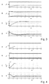
- FIGS. 3 and 4 are simulations performed as an example of execution.
- f 1 4 Hz
- f 2 10 Hz
- f 2 50 Hz
- Part A of each figure corresponds to the amplitude fraction of each oscillator relative to the reference amplitude if it received the entire torque of the energy source.
- the amplitude AT 2 0 chosen from the second oscillator is about 1 ⁇ 3.
- each oscillator stabilizes at its synchronized amplitude.
- Part B of each figure corresponds to the fraction of torque that each oscillator receives from the energy source. Note that for the examples of the figures the proportion of torque chosen for the second oscillator is about 10%. Thus at the end of respectively 2 and 1.5 seconds, each oscillator receives in a stabilized manner its proportion of torque.
- Part C of each figure corresponds to the operation of the second oscillator. We note that after 5.5 and 2 seconds respectively, the second oscillator stabilizes around its zero step.
- part D of each figure corresponds to the difference of state in seconds between each oscillator. We note that after 5 and 2 seconds respectively, the difference stabilizes at its zero value.
- the timepiece according to the invention is capable of displaying the time, and / or the time measured with a chronograph system, with a better resolution and / or a better accuracy while guaranteeing a great robustness, a consumption low and a minimal drift between the display of the time and the display of the measured time even if the latter is greater than one minute.
- the second oscillator preferably comprises a quality factor lower than that of the first oscillator and, preferably, less than 100 to obtain a faster stabilization, that is to say typically less than 2 seconds.
- a second clutch can be mounted on the wheel hours of the first gear 5 to avoid the addition of gearing in the second gear 25 to display the hours of the measured time. It is therefore understood that the second clutch would belong to the clutch device 44 and would trigger at the same time.
- the two oscillators being synchronized, the display of the hours would increment also in a synchronized manner.
- first oscillator is of the high frequency type
- the display of the time could be limited to hours and minutes from the first gear 5 in order to limit the propagation of couples induced by any shock at the high frequency oscillator.
- a second would then be displayed preferentially only on the second wheel 25.
- first and / or second oscillator is of the high frequency type, that is to say greater than or equal to 5 Hz
- a Clifford type oscillator can be used (see for example the document CH386344 incorporated by reference in this document). While when they have a frequency between 1 and 5 Hz, they will preferably be of the balance spring - spiral and Swiss lever escapement.
- the elastic coupling means can not be limited to a double wheel 42 cooperating with a spring 43 as illustrated in FIGS. figures 1 and 2 .
- Other elastic coupling means can be envisaged, for example those disclosed in the document PCT / EP2011 / 061244 incorporated by reference in this application.
- the second oscillator may comprise a weak anisochronism around the equilibrium amplitude and a strong anisochronism far from the amplitude of equilibrium, or vice versa.
Abstract
Description
L'invention se rapporte à une pièce d'horlogerie à oscillateurs couplés en mode chronographe et une telle pièce d'horlogerie comportant deux oscillateurs destinés à afficher au moins une valeur inférieure ou égale à la seconde avec une meilleure résolution et/ou une meilleure précision.The invention relates to a timepiece with oscillators coupled in chronograph mode and such a timepiece comprising two oscillators intended to display at least one value less than or equal to the second with a better resolution and / or a better accuracy .
Il est connu de former des pièces d'horlogerie dont la fréquence est augmentée pour améliorer la résolution. Toutefois, ces pièces d'horlogerie peuvent être très sensibles aux chocs ou très gourmandes en énergie ce qui les rend marginales.It is known to train timepieces whose frequency is increased to improve the resolution. However, these timepieces can be very sensitive to shocks or very greedy energy which makes them marginal.
On comprend donc qu'il est plus facile de fabriquer un calibre en montant un oscillateur basse fréquence, typiquement 4 Hz, pour afficher l'heure et un autre oscillateur haute fréquence, typiquement 10 ou 50 Hz, indépendant du premier pour afficher un temps mesuré avec une meilleure résolution. Toutefois, au bout de plusieurs secondes, on s'aperçoit que l'affichage des secondes de chaque oscillateur n'est plus le même ce qui peut poser des questions sur la qualité de la pièce d'horlogerie.It is therefore clear that it is easier to manufacture a template by mounting a low frequency oscillator, typically 4 Hz, to display the time and another high frequency oscillator, typically 10 or 50 Hz, independent of the first to display a measured time with better resolution. However, after several seconds, it becomes apparent that the display of the seconds of each oscillator is no longer the same, which can raise questions about the quality of the timepiece.
Le but de la présente invention est de pallier tout ou partie les inconvénients cités précédemment en proposant une pièce d'horlogerie capable d'afficher l'heure ou le temps mesuré avec un système chronographe avec une meilleure résolution tout en garantissant une robustesse habituelle pour une montre mécanique, une consommation d'énergie réduite et une dérive minime entre l'affichage de l'heure et l'affichage du temps mesuré même si ce dernier est supérieur à une minute.The object of the present invention is to overcome all or part of the disadvantages mentioned above by proposing a timepiece capable of displaying the time or time measured with a system. Chronograph with better resolution while maintaining the usual robustness for a mechanical watch, reduced power consumption and minimal drift between the time display and the measured time display even if the latter is greater than one minute .
A cet effet, l'invention se rapporte à une pièce d'horlogerie comportant un premier oscillateur oscillant à une première fréquence et relié par un premier rouage à une source d'énergie pour afficher l'heure et un système chronographe comportant un deuxième rouage relié au premier rouage via un dispositif d'embrayage permettant de sélectivement mesurer un temps caractérisée en ce que le système chronographe comporte en outre un deuxième oscillateur relié au deuxième rouage qui oscille à une deuxième fréquence et en ce que le deuxième rouage est relié au premier rouage par des moyens de couplage élastique afin de synchroniser la marche des deux oscillateurs à l'aide de la même source d'énergie lorsque le dispositif d'embrayage autorise ladite mesure d'un temps.For this purpose, the invention relates to a timepiece comprising a first oscillator oscillating at a first frequency and connected by a first gear to a power source to display the time and a chronograph system having a second gear connected the first gear via a clutch device for selectively measuring a time characterized in that the chronograph system further comprises a second oscillator connected to the second train which oscillates at a second frequency and in that the second wheel is connected to the first gear by elastic coupling means for synchronizing the operation of the two oscillators with the same energy source when the clutch device allows said measurement of a time.
On comprend donc que, même en cas de chocs, les variations de marche seront minimes grâce à la construction permettant la synchronisation des deux oscillateurs. Par conséquent, la pièce d'horlogerie selon l'invention est capable d'afficher l'heure, et/ou le temps mesuré avec un système chronographe, avec une meilleure résolution et/ou une meilleure précision tout en garantissant une grande robustesse, une consommation faible et une dérive minime entre l'affichage de l'heure et l'affichage du temps mesuré même si ce dernier est supérieur à une minute.It is therefore understandable that, even in the event of shocks, the variations in operation will be minimal thanks to the construction allowing the synchronization of the two oscillators. Therefore, the timepiece according to the invention is capable of displaying the time, and / or the time measured with a chronograph system, with a better resolution and / or a better accuracy while guaranteeing a great robustness, a low consumption and a slight drift between the display of the time and the display of the measured time even if the latter is greater than one minute.
Conformément à d'autres caractéristiques avantageuses de l'invention :
- les moyens de couplage élastique sont formés par un ressort reliant une roue du premier rouage avec une autre du deuxième rouage ;
- les moyens de couplage élastique relient les roues des secondes respectivement du premier rouage et du deuxième rouage ;
- le premier oscillateur reçoit le plus de couple de la source d'énergie et, préférentiellement, au moins 75% du couple ;
- le premier oscillateur possède un isochronisme de meilleure qualité que le deuxième oscillateur afin de faciliter la synchronisation de ce dernier ;
- le premier oscillateur comporte un facteur de qualité supérieur à celui du deuxième oscillateur ;
- le deuxième oscillateur comporte un facteur de qualité inférieur à 100 afin d'obtenir une stabilisation plus rapide ;
- selon un premier mode de réalisation, les première et deuxième fréquences sont identiques ;
- les deux fréquences sont supérieure à 5 Hz pour afficher avec une meilleure résolution et/ou une meilleure précision aussi bien l'heure que le temps mesuré ;
- selon un deuxième mode de réalisation, la première fréquence est plus élevée que la deuxième fréquence afin d'afficher l'heure avec une meilleure résolution et/ou une meilleure précision ;
- la première fréquence est au moins égale à 10 Hz et la deuxième fréquence entre 1 et 5 Hz ;
- selon un troisième mode de réalisation, la première fréquence est plus basse que la deuxième fréquence afin d'afficher le temps mesuré avec une meilleure résolution et/ou une meilleure précision ;
- la deuxième fréquence est au moins égale à 10 Hz et la première fréquence entre 3 et 5 Hz.
- the elastic coupling means are formed by a spring connecting a wheel of the first wheel with another of the second wheel;
- the elastic coupling means connect the wheels of the seconds respectively of the first wheel and the second wheel;
- the first oscillator receives the most torque from the energy source and, preferably, at least 75% of the torque;
- the first oscillator has an isochronism of better quality than the second oscillator to facilitate the synchronization of the latter;
- the first oscillator has a higher quality factor than the second oscillator;
- the second oscillator has a quality factor of less than 100 in order to obtain a faster stabilization;
- according to a first embodiment, the first and second frequencies are identical;
- the two frequencies are greater than 5 Hz to display with a better resolution and / or a better accuracy both the time and the measured time;
- according to a second embodiment, the first frequency is higher than the second frequency in order to display the time with a better resolution and / or a better accuracy;
- the first frequency is at least 10 Hz and the second frequency is between 1 and 5 Hz;
- according to a third embodiment, the first frequency is lower than the second frequency in order to display the measured time with a better resolution and / or a better accuracy;
- the second frequency is at least 10 Hz and the first frequency is between 3 and 5 Hz.
D'autres particularités et avantages ressortiront clairement de la description qui en est faite ci-après, à titre indicatif et nullement limitatif, en référence aux dessins annexés, dans lesquels :
- la
figure 1 est un exemple de pièce d'horlogerie selon l'invention ; - la
figure 2 est un exemple de moyens de couplage élastique selon l'invention ; - les
figures 3 et 4 sont des simulations de synchronisation pour deux exemples de pièces d'horlogerie selon l'invention.
- the
figure 1 is an example of a timepiece according to the invention; - the
figure 2 is an example of elastic coupling means according to the invention; - the
Figures 3 and 4 are synchronization simulations for two examples of timepieces according to the invention.
Comme illustré aux
Avantageusement selon l'invention, le système chronographe 51 comporte en outre un deuxième oscillateur 35 relié au deuxième rouage 25 et qui oscille à une deuxième fréquence ƒ 2. De plus, selon l'invention, le deuxième rouage 25 est relié, de manière avantageuse, au premier rouage 5 par des moyens de couplage élastique 41 afin de synchroniser la marche des deux oscillateurs 15, 35 à l'aide de la même source d'énergie 9 lorsque le dispositif d'embrayage 44 autorise ladite mesure d'un temps.Advantageously according to the invention, the
Comme visible dans l'exemple de la
Préférentiellement selon l'invention, les moyens de couplage élastique 41 sont formés par un ressort 43 reliant une roue du premier rouage 5 avec une autre du deuxième rouage 25. Comme illustré à la
Préférentiellement selon l'invention, on peut voir qu'une roue double 42 est utilisée. Comme mieux visible à la
Préférentiellement selon l'invention, l'affichage de l'heure, c'est-à-dire les heures, les minutes et, éventuellement, les secondes, est réalisé à partir du premier rouage 5. Alors que l'affichage du temps mesuré par le système chronographe 51 est, de manière préférée, réalisé à partir du deuxième rouage 25.Preferably according to the invention, the time display, that is to say the hours, the minutes and possibly the seconds, is made from the
Suivant l'application souhaitée pour la pièce d'horlogerie, les première ƒ 1 et deuxième ƒ 2 fréquences sont identiques ou non. Ainsi dans un premier mode de réalisation, les première et deuxième fréquences ƒ 1, ƒ 2 sont identiques et préférentiellement supérieures à 5 Hz pour afficher avec une meilleure résolution et/ou une meilleure précision aussi bien l'heure que le temps mesuré. Dans un tel mode de réalisation, les fréquences ƒ 1, ƒ 2 peuvent, par exemple, être égales à 10 Hz ou 50Hz pour afficher respectivement 1/20 ou 1 /100 de secondes.Depending on the desired application for the timepiece, the first ƒ 1 and second ƒ 2 frequencies are identical or not. Thus, in a first embodiment, the first and second frequencies ƒ 1 , ƒ 2 are identical and preferably greater than 5 Hz to display with a better resolution and / or a better accuracy both the time and the measured time. In such an embodiment, the frequencies ƒ 1 , ƒ 2 may, for example, be equal to 10 Hz or 50 Hz to respectively display 1/20 or 1/100 of seconds.
Dans un deuxième mode de réalisation, la première fréquence f1 est plus élevée que la deuxième fréquence f 2 afin d'afficher l'heure avec une meilleure résolution et/ou une meilleure précision. De manière similaire au premier mode de réalisation, la première fréquence f 1 est au moins égale à 10 Hz et la deuxième fréquence f2 est préférentiellement comprise entre 1 et 5 Hz. En effet, à titre d'exemple, il peut être souhaité que la seconde du temps mesuré s'incrémente d'un seul pas par seconde, c'est-à-dire que la deuxième fréquence f2 soit égale à 1 Hz, « à la manière » d'une montre à quartz.In a second embodiment, the first frequency f 1 is higher than the second frequency f 2 in order to display the time with a better resolution and / or a better accuracy. Similarly to the first embodiment, the first frequency f 1 is at least 10 Hz and the second frequency f 2 is preferably between 1 and 5 Hz. By way of example, it may be desired that the second of the measured time is incremented by a single step per second, that is to say that the second frequency f 2 is equal to 1 Hz, "in the manner" of a quartz watch.
Dans un troisième mode de réalisation, la première fréquence f1 est plus basse que la deuxième fréquence f2 afin d'afficher le temps mesuré avec une meilleure résolution et/ou une meilleure précision. Dans ce mode de réalisation, inverse au deuxième mode de réalisation, la deuxième fréquence f2 est au moins égale à 10 Hz et la première fréquence f1 est, préférentiellement, comprise entre 3 et 5 Hz.In a third embodiment, the first frequency f 1 is lower than the second frequency f 2 in order to display the measured time with better resolution and / or better accuracy. In this embodiment, inverse to the second embodiment, the second frequency f 2 is at least 10 Hz and the first frequency f 1 is preferably between 3 and 5 Hz.
Des simulations ont été développées ci-dessous afin de décrire la synchronisation entre ces deux oscillateurs 15, 35. Arbitrairement, le troisième mode de réalisation a été choisi pour l'explication. Ainsi, l'oscillateur 15 est choisi du type à basse fréquence et appelé premier oscillateur. De fait, dans l'exemple ci-dessous, le deuxième oscillateur sera l'oscillateur 35 du type à haute fréquence qui se synchronisera sur l'oscillateur 15 basse fréquence.Simulations have been developed below to describe the synchronization between these two
Préférentiellement selon l'invention, le deuxième oscillateur 35 est choisi avec un fort anisochronisme en fonction de l'amplitude, décrit par la pente d'anisochronisme Γ, ainsi que par l'amplitude ![]()
![]()
Les simulations montrent l'évolution des deux oscillateurs 15, 35, c'est-à-dire leurs amplitudes et leur état de déphasage au cours du temps et permettent ainsi de vérifier la possibilité de synchronisation ou non du deuxième oscillateur 35 sur le premier oscillateur 15.The simulations show the evolution of the two
Préférentiellement, le deuxième oscillateur 35 est construit de manière à ce que sa marche soit nulle lorsqu'il oscille à une amplitude ![]()
![]()
![]()
![]()
![]()
![]()
D'autre part, les moyens de couplage élastique 41 sont construits pour que le couple transmis au deuxième rouage 25 reste constant si les deux rouages 5, 25 tournent à la même vitesse, diminue si le deuxième rouage 25 avance plus rapidement que le premier rouage 5 (le ressort 43 se désarme) et augmente si le deuxième rouage 25 avance moins rapidement que le premier rouage 5 (le ressort 43 s'arme).On the other hand, the elastic coupling means 41 are constructed so that the torque transmitted to the
Si les conditions ci-dessus sont satisfaites, la pièce d'horlogerie va toujours évoluer vers la situation stable où le deuxième oscillateur 35 oscille à l'amplitude ![]()
![]()
![]()
![]()
Par conséquent, si le deuxième oscillateur 35 reçoit un couple inférieur à M 2, son amplitude diminue, c'est-à-dire possède une amplitude inférieure à ![]()
![]()
On comprend donc que le deuxième rouage 25 va tourner plus lentement que le premier rouage 5 en armant le ressort 43 de couplage, c'est-à-dire en augmentant le couple transmis au deuxième rouage 25. Par conséquent, le couple augmentant, l'amplitude du deuxième oscillateur 25 se corrige automatiquement. On remarque donc qu'à la fois le couple et l'amplitude du deuxième oscillateur 35 se synchronisent structurellement sur le couple stable M 2 et de l'amplitude stable ![]()
![]()
De manière analogue, si le couple reçu dépasse le couple M 2 alors l'amplitude du deuxième oscillateur 35 devient plus grande que la valeur ![]()
![]()
![]()
![]()
On voit donc que quelle que soit la situation dans laquelle on se trouve, que ce soit au démarrage de la montre ou après un choc, le système va toujours évoluer pour se stabiliser sur la situation stable où le couple sur le deuxième rouage 25 vaut M 2 et l'amplitude du deuxième oscillateur 35 vaut ![]()
![]()
De manière préférée selon l'invention, on suppose que le couple du barillet 9 et la fréquence f1 , f 2 des deux oscillateurs 15, 35 sont des paramètres donnés. On comprend donc que les paramètres encore à choisir sont :
- la « taille » des deux oscillateurs 15, 35 (par exemple les inerties I 1 , I2 si les résonateurs 3, 23 sont du type balancier ― spiral) ;
- les facteurs de qualité des deux oscillateurs 15, 35 : Q1, Q2 (qui est fonction de la taille de l'oscillateur) ;
- la pente d'anisochronisme du deuxième oscillateur : Γ ;
- l'amplitude du deuxième oscillateur pour laquelle sa marche est nulle :

- le couple M 2 du ressort 43 ;
- la rigidité angulaire K du ressort 43.
- the "size" of the two
oscillators 15, 35 (for example the inertias I 1 , I 2 if theresonators - the quality factors of the two
oscillators 15, 35: Q 1 , Q 2 (which is a function of the size of the oscillator); - the anisochronism slope of the second oscillator: Γ ;
- the amplitude of the second oscillator for which its progress is null:
- the torque M 2 of the
spring 43; - the angular rigidity K of the
spring 43.
Préférentiellement selon l'invention, on choisit les paramètres de la manière suivante :
- fraction du couple total que l'on souhaite transmettre au deuxième oscillateur, ce qui donne la valeur du couple M 2. Selon l'invention, le premier oscillateur 15, reçoit le plus de couple par la source d'énergie 9 et, préférentiellement, au moins 75%.
amplitude 
- taille du deuxième oscillateur (par exemple son inertie) pour que l'amplitude de
stabilisation soit 
- taille du premier oscillateur (par exemple son inertie) pour que l'amplitude de stabilisation soit acceptable (par l'intermédiaire du facteur de qualité) ;
- pente d'anisochronisme Γ du deuxième oscillateur 35 ;
- rigidité K du ressort 43.
- fraction of the total torque that it is desired to transmit to the second oscillator, which gives the value of the torque M 2 . According to the invention, the
first oscillator 15, receives the most torque by theenergy source 9 and, preferably, at least 75%. - amplitude
- size of the second oscillator (for example its inertia) so that the amplitude of stabilization is
- size of the first oscillator (for example its inertia) so that the stabilization amplitude is acceptable (via the quality factor);
- anisochronism slope Γ of the
second oscillator 35; - stiffness K of the
spring 43.
Avantageusement selon l'invention, il est préféré également de « régler » K et Γ pour que :
- le couple transmis au rouage 25 ne devienne jamais nul ;
- la marche du deuxième oscillateur 35 reste proche de sa fréquence zéro ;
- l'écart d'état entre les deux oscillateurs 15, 35 soit faible au « démarrage » ;
- le temps de stabilisation soit suffisamment court.
- the torque transmitted to the
wheel 25 never becomes zero; - the step of the
second oscillator 35 remains close to its zero frequency; - the difference in state between the two
oscillators - the stabilization time is sufficiently short.
Empiriquement, il a été montré qu'il est préférable que le produit K.Γ soit maintenu identique pour avoir le même temps de stabilisation dans l'approximation continue. Ainsi,augmenter K (et donc diminuer Γ d'autant) permet de diminuer les fluctuations d'amplitude et de couple (donc éviter que le couple s'annule). Par contre, cela augmente aussi l'écart d'état maximal avant la stabilisation, ainsi que la marche instantanée, qui peut devenir extrême. Il faut donc trouver un compromis entre ces deux effets.Empirically, it has been shown that it is preferable that the product K. Γ be kept identical to have the same stabilization time in the continuous approximation. Thus, increasing K (and thus decreasing Γ all the same) makes it possible to reduce the amplitude and torque fluctuations (thus preventing the pair from being canceled). On the other hand, it also increases the maximum state difference before stabilization, as well as instantaneous walking, which can become extreme. We must therefore find a compromise between these two effects.
Il est également apparu qu'augmenter la fréquence de l'oscillateur qui se synchronise (ci-dessus le deuxième oscillateur 35) permet de diminuer le temps de stabilisation. Enfin, au cours des tests, il a été montré que diminuer le facteur de qualité de l'oscillateur qui se synchronise (ci-dessus le deuxième oscillateur) permet aussi de diminuer le temps de stabilisation.It has also been found that increasing the frequency of the synchronizing oscillator (above the second oscillator 35) makes it possible to decrease the stabilization time. Finally, during the tests, it has been shown that reducing the quality factor of the oscillator that synchronizes (above the second oscillator) also makes it possible to reduce the stabilization time.
Les
La partie A de chaque figure correspond à la fraction d'amplitude de chaque oscillateur par rapport à l'amplitude de référence s'il recevait la totalité du couple de la source d'énergie. On remarque que pour les exemples des figures l'amplitude ![]()
![]()
La partie B de chaque figure correspond à la fraction de couple que chaque oscillateur reçoit de la source d'énergie. On remarque que pour les exemples des figures la proportion de couple choisi pour le deuxième oscillateur est d'environ 10%. Ainsi au bout de respectivement 2 et 1,5 secondes, chaque oscillateur reçoit de manière stabilisée sa proportion de couple.Part B of each figure corresponds to the fraction of torque that each oscillator receives from the energy source. Note that for the examples of the figures the proportion of torque chosen for the second oscillator is about 10%. Thus at the end of respectively 2 and 1.5 seconds, each oscillator receives in a stabilized manner its proportion of torque.
La partie C de chaque figure correspond à la marche du deuxième oscillateur. On remarque ainsi qu'au bout de respectivement 5,5 et 2 secondes, le deuxième oscillateur se stabilise autour de sa marche nulle.Part C of each figure corresponds to the operation of the second oscillator. We note that after 5.5 and 2 seconds respectively, the second oscillator stabilizes around its zero step.
Enfin, la partie D de chaque figure correspond à la différence d'état en secondes entre chaque oscillateur. On remarque ainsi qu'au bout de respectivement 5 et 2 secondes, la différence se stabilise à sa valeur nulle.Finally, the part D of each figure corresponds to the difference of state in seconds between each oscillator. We note that after 5 and 2 seconds respectively, the difference stabilizes at its zero value.
Au vu des parties A-D des
De plus, au cours des tests, il a été trouvé qu'en plus du fait que le premier oscillateur possède préférentiellement un isochronisme de meilleur qualité que le deuxième oscillateur afin de faciliter la synchronisation de ce dernier, le deuxième oscillateur comporte de manière préférée un facteur de qualité inférieur à celui du premier oscillateur et, préférentiellement, inférieur à 100 afin d'obtenir une stabilisation plus rapide, c'est-à-dire typiquement inférieure à 2 secondes.Moreover, during the tests, it has been found that in addition to the fact that the first oscillator preferably has an isochronism of better quality than the second oscillator in order to facilitate synchronization of the latter, the second oscillator preferably comprises a quality factor lower than that of the first oscillator and, preferably, less than 100 to obtain a faster stabilization, that is to say typically less than 2 seconds.
Bien entendu, la présente invention ne se limite pas à l'exemple illustré mais est susceptible de diverses variantes et modifications qui apparaîtront à l'homme de l'art. En particulier, un deuxième embrayage peut être monté sur la roue des heures du premier rouage 5 afin d'éviter l'ajout de démultiplication dans le deuxième rouage 25 pour afficher les heures du temps mesuré. On comprend donc que le deuxième embrayage appartiendrait au dispositif d'embrayage 44 et se déclencherait en même temps. Avantageusement selon l'invention, les deux oscillateurs étant synchronisés, l'affichage des heures s'incrémenterait également de manière synchronisée.Of course, the present invention is not limited to the illustrated example but is susceptible of various variations and modifications that will occur to those skilled in the art. In particular, a second clutch can be mounted on the wheel hours of the
De plus, on peut se trouver dans le premier ou le deuxième mode de réalisation sans que les conclusions relatives au troisième mode de réalisation diffèrent. Ainsi, à l'inverse de l'exemple ci-dessus, si le premier oscillateur est du type haute fréquence, l'affichage de l'heure pourrait être limité aux heures et minutes à partir du premier rouage 5 afin de limiter la propagation de couples induits par un choc quelconque au niveau de l'oscillateur haute fréquence. Une seconde ne serait alors affichée préférentiellement que sur le deuxième rouage 25.In addition, one may be in the first or second embodiment without the conclusions relating to the third embodiment differ. Thus, unlike the example above, if the first oscillator is of the high frequency type, the display of the time could be limited to hours and minutes from the
En outre, lorsque le premier et/ou le deuxième oscillateur est du type haute fréquence, c'est-à-dire supérieur ou égale à 5 Hz, un oscillateur du type Clifford peut être utilisé (voir par exemple le document
Bien entendu, les moyens de couplage élastique ne sauraient se limiter à une double roue 42 coopérant avec un ressort 43 comme illustrés dans les
Enfin, il est probable d'encore optimiser le comportement du système en ayant un anisochronisme du deuxième oscillateur qui ne soit pas linéaire. A titre d'exemple, le deuxième oscillateur peut comporter un faible anisochronisme autour de l'amplitude d'équilibre et un fort anisochronisme loin de l'amplitude d'équilibre, ou inversement.Finally, it is likely to further optimize the behavior of the system by having an anisochronism of the second oscillator that is not linear. By way of example, the second oscillator may comprise a weak anisochronism around the equilibrium amplitude and a strong anisochronism far from the amplitude of equilibrium, or vice versa.
Claims (14)
Priority Applications (7)
| Application Number | Priority Date | Filing Date | Title |
|---|---|---|---|
| CH01530/11A CH705493B1 (en) | 2011-09-15 | 2011-09-15 | Timepiece with oscillators coupled in chronograph mode. |
| EP11181505.6A EP2570869B1 (en) | 2011-09-15 | 2011-09-15 | Timepiece with oscillators coupled in chronograph mode |
| US13/609,786 US8905630B2 (en) | 2011-09-15 | 2012-09-11 | Timepiece with coupled oscillators in chronograph mode |
| RU2012139632/12A RU2598299C2 (en) | 2011-09-15 | 2012-09-14 | Clock with connected oscillators in chronograph mode |
| CN201210342577.1A CN102998967B (en) | 2011-09-15 | 2012-09-14 | Timepiece with oscillators coupled together in chronograph mode |
| JP2012203954A JP5486059B2 (en) | 2011-09-15 | 2012-09-18 | Timepiece with vibrators connected in chronograph mode |
| HK13110950.2A HK1183713A1 (en) | 2011-09-15 | 2013-09-25 | Timepiece with coupled oscillators in chronograph mode |
Applications Claiming Priority (1)
| Application Number | Priority Date | Filing Date | Title |
|---|---|---|---|
| EP11181505.6A EP2570869B1 (en) | 2011-09-15 | 2011-09-15 | Timepiece with oscillators coupled in chronograph mode |
Publications (2)
| Publication Number | Publication Date |
|---|---|
| EP2570869A1 true EP2570869A1 (en) | 2013-03-20 |
| EP2570869B1 EP2570869B1 (en) | 2016-04-06 |
Family
ID=45954212
Family Applications (1)
| Application Number | Title | Priority Date | Filing Date |
|---|---|---|---|
| EP11181505.6A Active EP2570869B1 (en) | 2011-09-15 | 2011-09-15 | Timepiece with oscillators coupled in chronograph mode |
Country Status (7)
| Country | Link |
|---|---|
| US (1) | US8905630B2 (en) |
| EP (1) | EP2570869B1 (en) |
| JP (1) | JP5486059B2 (en) |
| CN (1) | CN102998967B (en) |
| CH (1) | CH705493B1 (en) |
| HK (1) | HK1183713A1 (en) |
| RU (1) | RU2598299C2 (en) |
Cited By (2)
| Publication number | Priority date | Publication date | Assignee | Title |
|---|---|---|---|---|
| KR20150028830A (en) * | 2012-06-29 | 2015-03-16 | 지멘스 인더스트리 인코포레이티드 | Electrical contact apparatus, assemblies, and methods of operation |
| EP3382468A1 (en) * | 2017-03-30 | 2018-10-03 | The Swatch Group Research and Development Ltd | Movement with extension of running reserve |
Families Citing this family (4)
| Publication number | Priority date | Publication date | Assignee | Title |
|---|---|---|---|---|
| EP2874023A1 (en) * | 2013-11-13 | 2015-05-20 | ETA SA Manufacture Horlogère Suisse | Timepiece comprising a decoupling between the means for transmitting power and the counting means |
| CH710115A2 (en) * | 2014-09-09 | 2016-03-15 | Swatch Group Res & Dev Ltd | Mobile module for synchronization of clock of the same frequency resonators. |
| CH711928A2 (en) * | 2015-12-18 | 2017-06-30 | Montres Breguet Sa | Coupled clock oscillators. |
| EP3770695B1 (en) * | 2019-07-23 | 2022-01-12 | Omega SA | Timepiece stop-cage with blade for stopping the cage |
Citations (3)
| Publication number | Priority date | Publication date | Assignee | Title |
|---|---|---|---|---|
| CH386344A (en) | 1961-06-01 | 1964-08-14 | Horstmann Gear Co Ltd | Operating mechanism for a time measuring device, in particular for a pendulum or clock |
| EP2141555A1 (en) * | 2008-07-04 | 2010-01-06 | The Swatch Group Research and Development Ltd. | Coupled resonators for timepiece |
| EP2221676A1 (en) * | 2009-02-24 | 2010-08-25 | Montres Breguet SA | Timepiece including a chronograph and a watch |
Family Cites Families (8)
| Publication number | Priority date | Publication date | Assignee | Title |
|---|---|---|---|---|
| JPH11183652A (en) * | 1997-12-22 | 1999-07-09 | Seiko Instruments Inc | Chronograph clock |
| ATE390654T1 (en) * | 2002-02-01 | 2008-04-15 | Tag Heuer Sa | DEVICE WITH CLOCK MOVEMENT AND CHRONOGRAPH MODULE |
| WO2005111742A1 (en) * | 2004-04-15 | 2005-11-24 | Montres Breguet Sa | Watch comprising at least two tourbillons |
| ATE470890T1 (en) * | 2005-03-30 | 2010-06-15 | Montres Breguet Sa | WATCH WITH AT LEAST TWO REGULATION SYSTEMS |
| EP1843227A1 (en) * | 2006-04-07 | 2007-10-10 | The Swatch Group Research and Development Ltd. | Coupled resonator for control system |
| CH699081A2 (en) * | 2008-07-04 | 2010-01-15 | Swatch Group Res & Dev Ltd | High and low frequency resonator assembly for timepiece i.e. watch, has balance spring arranged between square inertial masses for coupling high and low frequency resonators, where inertial masses are constituted by respective balances |
| CH700747B1 (en) * | 2009-04-09 | 2014-07-31 | Rudis Sylva S A | mechanical oscillator for clock movement. |
| CH702062B1 (en) * | 2009-10-26 | 2022-01-31 | Mft Dhorlogerie Audemars Piguet Sa | Regulating organ comprising at least two pendulums, a watch movement as well as a timepiece comprising such an organ. |
-
2011
- 2011-09-15 EP EP11181505.6A patent/EP2570869B1/en active Active
- 2011-09-15 CH CH01530/11A patent/CH705493B1/en unknown
-
2012
- 2012-09-11 US US13/609,786 patent/US8905630B2/en active Active
- 2012-09-14 CN CN201210342577.1A patent/CN102998967B/en active Active
- 2012-09-14 RU RU2012139632/12A patent/RU2598299C2/en not_active IP Right Cessation
- 2012-09-18 JP JP2012203954A patent/JP5486059B2/en active Active
-
2013
- 2013-09-25 HK HK13110950.2A patent/HK1183713A1/en unknown
Patent Citations (3)
| Publication number | Priority date | Publication date | Assignee | Title |
|---|---|---|---|---|
| CH386344A (en) | 1961-06-01 | 1964-08-14 | Horstmann Gear Co Ltd | Operating mechanism for a time measuring device, in particular for a pendulum or clock |
| EP2141555A1 (en) * | 2008-07-04 | 2010-01-06 | The Swatch Group Research and Development Ltd. | Coupled resonators for timepiece |
| EP2221676A1 (en) * | 2009-02-24 | 2010-08-25 | Montres Breguet SA | Timepiece including a chronograph and a watch |
Cited By (4)
| Publication number | Priority date | Publication date | Assignee | Title |
|---|---|---|---|---|
| KR20150028830A (en) * | 2012-06-29 | 2015-03-16 | 지멘스 인더스트리 인코포레이티드 | Electrical contact apparatus, assemblies, and methods of operation |
| EP3382468A1 (en) * | 2017-03-30 | 2018-10-03 | The Swatch Group Research and Development Ltd | Movement with extension of running reserve |
| US10514659B2 (en) | 2017-03-30 | 2019-12-24 | The Swatch Group Research And Development Ltd | Movement with power reserve extension |
| US10816934B2 (en) | 2017-03-30 | 2020-10-27 | The Swatch Group Research And Development Ltd | Movement with power reserve extension |
Also Published As
| Publication number | Publication date |
|---|---|
| RU2598299C2 (en) | 2016-09-20 |
| CH705493B1 (en) | 2019-04-30 |
| JP5486059B2 (en) | 2014-05-07 |
| CH705493A2 (en) | 2013-03-15 |
| JP2013064737A (en) | 2013-04-11 |
| EP2570869B1 (en) | 2016-04-06 |
| CN102998967A (en) | 2013-03-27 |
| US8905630B2 (en) | 2014-12-09 |
| HK1183713A1 (en) | 2014-01-03 |
| CN102998967B (en) | 2015-06-10 |
| US20130070568A1 (en) | 2013-03-21 |
| RU2012139632A (en) | 2014-03-20 |
Similar Documents
| Publication | Publication Date | Title |
|---|---|---|
| EP2570870B1 (en) | Timepiece with permanently coupled oscillators | |
| EP2570869B1 (en) | Timepiece with oscillators coupled in chronograph mode | |
| EP3410236B1 (en) | Device and method for adjusting the rate and correcting the state of a watch | |
| EP2514094B1 (en) | Resonator thermocompensated at least to the first and second orders | |
| EP2090941B1 (en) | Mechanical oscillator | |
| EP3410235B1 (en) | Device and method for adjusting the rate of a watch | |
| EP2761378B1 (en) | Oscillator with tuning fork for mechanical timepiece movement | |
| EP3030938B1 (en) | Regulator system for mechanical watch | |
| EP2405313B1 (en) | Spiral with immobile mass centre | |
| EP3602206B1 (en) | Mechanical timepiece comprising a movement of which the operation is improved by a correction device | |
| EP2570867B1 (en) | Oszillatoren, die durch eine intermittierende Hemmung synchronisiert sind | |
| WO2018177779A1 (en) | Timepiece comprising a mechanical movement improved by a correction device | |
| EP2613205A2 (en) | Regulating mechanism for watch or chronograph | |
| EP3842876A1 (en) | Timepiece fitted with a mechanical movement and a device for correcting the time displayed | |
| EP3485334B1 (en) | Method for adjusting the running of a timepiece | |
| CH713636A2 (en) | Mechanical timepiece comprising a movement whose progress is improved by a correction device. | |
| EP2802941B1 (en) | Regulating member for a mechanical chronograph | |
| CH705970B1 (en) | Clock mechanism comprising a vibrating oscillator. | |
| EP3176652B1 (en) | Movement for a timepiece and timepiece comprising such a movement | |
| CH707187A2 (en) | Resonator clockwork and assembly comprising such a resonator and an escapement mechanism. | |
| CH705969B1 (en) | Regulating organ for a watch movement. | |
| CH705495A2 (en) | Timepiece i.e. mechanical wrist watch, has resonator oscillating at frequency, where resonator cooperates with main escapement to synchronize maintenance of another resonator to frequency of former resonator |
Legal Events
| Date | Code | Title | Description |
|---|---|---|---|
| PUAI | Public reference made under article 153(3) epc to a published international application that has entered the european phase |
Free format text: ORIGINAL CODE: 0009012 |
|
| AK | Designated contracting states |
Kind code of ref document: A1 Designated state(s): AL AT BE BG CH CY CZ DE DK EE ES FI FR GB GR HR HU IE IS IT LI LT LU LV MC MK MT NL NO PL PT RO RS SE SI SK SM TR |
|
| AX | Request for extension of the european patent |
Extension state: BA ME |
|
| 17P | Request for examination filed |
Effective date: 20130920 |
|
| RBV | Designated contracting states (corrected) |
Designated state(s): AL AT BE BG CH CY CZ DE DK EE ES FI FR GB GR HR HU IE IS IT LI LT LU LV MC MK MT NL NO PL PT RO RS SE SI SK SM TR |
|
| GRAP | Despatch of communication of intention to grant a patent |
Free format text: ORIGINAL CODE: EPIDOSNIGR1 |
|
| RIC1 | Information provided on ipc code assigned before grant |
Ipc: G04B 17/22 20060101AFI20151207BHEP Ipc: G04F 7/08 20060101ALI20151207BHEP Ipc: G04B 17/26 20060101ALI20151207BHEP |
|
| INTG | Intention to grant announced |
Effective date: 20160108 |
|
| GRAS | Grant fee paid |
Free format text: ORIGINAL CODE: EPIDOSNIGR3 |
|
| GRAA | (expected) grant |
Free format text: ORIGINAL CODE: 0009210 |
|
| AK | Designated contracting states |
Kind code of ref document: B1 Designated state(s): AL AT BE BG CH CY CZ DE DK EE ES FI FR GB GR HR HU IE IS IT LI LT LU LV MC MK MT NL NO PL PT RO RS SE SI SK SM TR |
|
| REG | Reference to a national code |
Ref country code: GB Ref legal event code: FG4D Free format text: NOT ENGLISH |
|
| REG | Reference to a national code |
Ref country code: AT Ref legal event code: REF Ref document number: 788434 Country of ref document: AT Kind code of ref document: T Effective date: 20160415 Ref country code: CH Ref legal event code: EP Ref country code: CH Ref legal event code: NV Representative=s name: ICB INGENIEURS CONSEILS EN BREVETS SA, CH |
|
| REG | Reference to a national code |
Ref country code: IE Ref legal event code: FG4D Free format text: LANGUAGE OF EP DOCUMENT: FRENCH |
|
| REG | Reference to a national code |
Ref country code: DE Ref legal event code: R096 Ref document number: 602011024836 Country of ref document: DE |
|
| REG | Reference to a national code |
Ref country code: LT Ref legal event code: MG4D Ref country code: NL Ref legal event code: MP Effective date: 20160406 |
|
| REG | Reference to a national code |
Ref country code: AT Ref legal event code: MK05 Ref document number: 788434 Country of ref document: AT Kind code of ref document: T Effective date: 20160406 |
|
| REG | Reference to a national code |
Ref country code: FR Ref legal event code: PLFP Year of fee payment: 6 |
|
| PG25 | Lapsed in a contracting state [announced via postgrant information from national office to epo] |
Ref country code: NL Free format text: LAPSE BECAUSE OF FAILURE TO SUBMIT A TRANSLATION OF THE DESCRIPTION OR TO PAY THE FEE WITHIN THE PRESCRIBED TIME-LIMIT Effective date: 20160406 |
|
| PG25 | Lapsed in a contracting state [announced via postgrant information from national office to epo] |
Ref country code: IS Free format text: LAPSE BECAUSE OF FAILURE TO SUBMIT A TRANSLATION OF THE DESCRIPTION OR TO PAY THE FEE WITHIN THE PRESCRIBED TIME-LIMIT Effective date: 20160806 Ref country code: LT Free format text: LAPSE BECAUSE OF FAILURE TO SUBMIT A TRANSLATION OF THE DESCRIPTION OR TO PAY THE FEE WITHIN THE PRESCRIBED TIME-LIMIT Effective date: 20160406 Ref country code: NO Free format text: LAPSE BECAUSE OF FAILURE TO SUBMIT A TRANSLATION OF THE DESCRIPTION OR TO PAY THE FEE WITHIN THE PRESCRIBED TIME-LIMIT Effective date: 20160706 Ref country code: FI Free format text: LAPSE BECAUSE OF FAILURE TO SUBMIT A TRANSLATION OF THE DESCRIPTION OR TO PAY THE FEE WITHIN THE PRESCRIBED TIME-LIMIT Effective date: 20160406 Ref country code: PL Free format text: LAPSE BECAUSE OF FAILURE TO SUBMIT A TRANSLATION OF THE DESCRIPTION OR TO PAY THE FEE WITHIN THE PRESCRIBED TIME-LIMIT Effective date: 20160406 |
|
| PG25 | Lapsed in a contracting state [announced via postgrant information from national office to epo] |
Ref country code: GR Free format text: LAPSE BECAUSE OF FAILURE TO SUBMIT A TRANSLATION OF THE DESCRIPTION OR TO PAY THE FEE WITHIN THE PRESCRIBED TIME-LIMIT Effective date: 20160707 Ref country code: HR Free format text: LAPSE BECAUSE OF FAILURE TO SUBMIT A TRANSLATION OF THE DESCRIPTION OR TO PAY THE FEE WITHIN THE PRESCRIBED TIME-LIMIT Effective date: 20160406 Ref country code: RS Free format text: LAPSE BECAUSE OF FAILURE TO SUBMIT A TRANSLATION OF THE DESCRIPTION OR TO PAY THE FEE WITHIN THE PRESCRIBED TIME-LIMIT Effective date: 20160406 Ref country code: PT Free format text: LAPSE BECAUSE OF FAILURE TO SUBMIT A TRANSLATION OF THE DESCRIPTION OR TO PAY THE FEE WITHIN THE PRESCRIBED TIME-LIMIT Effective date: 20160808 Ref country code: ES Free format text: LAPSE BECAUSE OF FAILURE TO SUBMIT A TRANSLATION OF THE DESCRIPTION OR TO PAY THE FEE WITHIN THE PRESCRIBED TIME-LIMIT Effective date: 20160406 Ref country code: AT Free format text: LAPSE BECAUSE OF FAILURE TO SUBMIT A TRANSLATION OF THE DESCRIPTION OR TO PAY THE FEE WITHIN THE PRESCRIBED TIME-LIMIT Effective date: 20160406 Ref country code: SE Free format text: LAPSE BECAUSE OF FAILURE TO SUBMIT A TRANSLATION OF THE DESCRIPTION OR TO PAY THE FEE WITHIN THE PRESCRIBED TIME-LIMIT Effective date: 20160406 Ref country code: LV Free format text: LAPSE BECAUSE OF FAILURE TO SUBMIT A TRANSLATION OF THE DESCRIPTION OR TO PAY THE FEE WITHIN THE PRESCRIBED TIME-LIMIT Effective date: 20160406 |
|
| PG25 | Lapsed in a contracting state [announced via postgrant information from national office to epo] |
Ref country code: IT Free format text: LAPSE BECAUSE OF FAILURE TO SUBMIT A TRANSLATION OF THE DESCRIPTION OR TO PAY THE FEE WITHIN THE PRESCRIBED TIME-LIMIT Effective date: 20160406 |
|
| REG | Reference to a national code |
Ref country code: DE Ref legal event code: R097 Ref document number: 602011024836 Country of ref document: DE |
|
| PG25 | Lapsed in a contracting state [announced via postgrant information from national office to epo] |
Ref country code: SK Free format text: LAPSE BECAUSE OF FAILURE TO SUBMIT A TRANSLATION OF THE DESCRIPTION OR TO PAY THE FEE WITHIN THE PRESCRIBED TIME-LIMIT Effective date: 20160406 Ref country code: CZ Free format text: LAPSE BECAUSE OF FAILURE TO SUBMIT A TRANSLATION OF THE DESCRIPTION OR TO PAY THE FEE WITHIN THE PRESCRIBED TIME-LIMIT Effective date: 20160406 Ref country code: DK Free format text: LAPSE BECAUSE OF FAILURE TO SUBMIT A TRANSLATION OF THE DESCRIPTION OR TO PAY THE FEE WITHIN THE PRESCRIBED TIME-LIMIT Effective date: 20160406 Ref country code: EE Free format text: LAPSE BECAUSE OF FAILURE TO SUBMIT A TRANSLATION OF THE DESCRIPTION OR TO PAY THE FEE WITHIN THE PRESCRIBED TIME-LIMIT Effective date: 20160406 Ref country code: RO Free format text: LAPSE BECAUSE OF FAILURE TO SUBMIT A TRANSLATION OF THE DESCRIPTION OR TO PAY THE FEE WITHIN THE PRESCRIBED TIME-LIMIT Effective date: 20160406 |
|
| PLBE | No opposition filed within time limit |
Free format text: ORIGINAL CODE: 0009261 |
|
| STAA | Information on the status of an ep patent application or granted ep patent |
Free format text: STATUS: NO OPPOSITION FILED WITHIN TIME LIMIT |
|
| PG25 | Lapsed in a contracting state [announced via postgrant information from national office to epo] |
Ref country code: SM Free format text: LAPSE BECAUSE OF FAILURE TO SUBMIT A TRANSLATION OF THE DESCRIPTION OR TO PAY THE FEE WITHIN THE PRESCRIBED TIME-LIMIT Effective date: 20160406 Ref country code: BE Free format text: LAPSE BECAUSE OF NON-PAYMENT OF DUE FEES Effective date: 20160930 |
|
| 26N | No opposition filed |
Effective date: 20170110 |
|
| PG25 | Lapsed in a contracting state [announced via postgrant information from national office to epo] |
Ref country code: MC Free format text: LAPSE BECAUSE OF FAILURE TO SUBMIT A TRANSLATION OF THE DESCRIPTION OR TO PAY THE FEE WITHIN THE PRESCRIBED TIME-LIMIT Effective date: 20160406 |
|
| PG25 | Lapsed in a contracting state [announced via postgrant information from national office to epo] |
Ref country code: SI Free format text: LAPSE BECAUSE OF FAILURE TO SUBMIT A TRANSLATION OF THE DESCRIPTION OR TO PAY THE FEE WITHIN THE PRESCRIBED TIME-LIMIT Effective date: 20160406 |
|
| REG | Reference to a national code |
Ref country code: IE Ref legal event code: MM4A |
|
| PG25 | Lapsed in a contracting state [announced via postgrant information from national office to epo] |
Ref country code: IE Free format text: LAPSE BECAUSE OF NON-PAYMENT OF DUE FEES Effective date: 20160915 |
|
| REG | Reference to a national code |
Ref country code: FR Ref legal event code: PLFP Year of fee payment: 7 |
|
| PG25 | Lapsed in a contracting state [announced via postgrant information from national office to epo] |
Ref country code: LU Free format text: LAPSE BECAUSE OF NON-PAYMENT OF DUE FEES Effective date: 20160915 |
|
| REG | Reference to a national code |
Ref country code: BE Ref legal event code: MM Effective date: 20160930 |
|
| PG25 | Lapsed in a contracting state [announced via postgrant information from national office to epo] |
Ref country code: HU Free format text: LAPSE BECAUSE OF FAILURE TO SUBMIT A TRANSLATION OF THE DESCRIPTION OR TO PAY THE FEE WITHIN THE PRESCRIBED TIME-LIMIT; INVALID AB INITIO Effective date: 20110915 Ref country code: CY Free format text: LAPSE BECAUSE OF FAILURE TO SUBMIT A TRANSLATION OF THE DESCRIPTION OR TO PAY THE FEE WITHIN THE PRESCRIBED TIME-LIMIT Effective date: 20160406 |
|
| PG25 | Lapsed in a contracting state [announced via postgrant information from national office to epo] |
Ref country code: TR Free format text: LAPSE BECAUSE OF FAILURE TO SUBMIT A TRANSLATION OF THE DESCRIPTION OR TO PAY THE FEE WITHIN THE PRESCRIBED TIME-LIMIT Effective date: 20160406 Ref country code: MK Free format text: LAPSE BECAUSE OF FAILURE TO SUBMIT A TRANSLATION OF THE DESCRIPTION OR TO PAY THE FEE WITHIN THE PRESCRIBED TIME-LIMIT Effective date: 20160406 Ref country code: MT Free format text: LAPSE BECAUSE OF FAILURE TO SUBMIT A TRANSLATION OF THE DESCRIPTION OR TO PAY THE FEE WITHIN THE PRESCRIBED TIME-LIMIT Effective date: 20160406 |
|
| PG25 | Lapsed in a contracting state [announced via postgrant information from national office to epo] |
Ref country code: BG Free format text: LAPSE BECAUSE OF FAILURE TO SUBMIT A TRANSLATION OF THE DESCRIPTION OR TO PAY THE FEE WITHIN THE PRESCRIBED TIME-LIMIT Effective date: 20160406 |
|
| REG | Reference to a national code |
Ref country code: FR Ref legal event code: PLFP Year of fee payment: 8 |
|
| PG25 | Lapsed in a contracting state [announced via postgrant information from national office to epo] |
Ref country code: AL Free format text: LAPSE BECAUSE OF FAILURE TO SUBMIT A TRANSLATION OF THE DESCRIPTION OR TO PAY THE FEE WITHIN THE PRESCRIBED TIME-LIMIT Effective date: 20160406 |
|
| P01 | Opt-out of the competence of the unified patent court (upc) registered |
Effective date: 20230615 |
|
| PGFP | Annual fee paid to national office [announced via postgrant information from national office to epo] |
Ref country code: GB Payment date: 20230823 Year of fee payment: 13 |
|
| PGFP | Annual fee paid to national office [announced via postgrant information from national office to epo] |
Ref country code: FR Payment date: 20230822 Year of fee payment: 13 Ref country code: DE Payment date: 20230822 Year of fee payment: 13 |
|
| PGFP | Annual fee paid to national office [announced via postgrant information from national office to epo] |
Ref country code: CH Payment date: 20231001 Year of fee payment: 13 |