EP2570735A1 - Vapour extractor system and method for operating same - Google Patents
Vapour extractor system and method for operating same Download PDFInfo
- Publication number
- EP2570735A1 EP2570735A1 EP12183183A EP12183183A EP2570735A1 EP 2570735 A1 EP2570735 A1 EP 2570735A1 EP 12183183 A EP12183183 A EP 12183183A EP 12183183 A EP12183183 A EP 12183183A EP 2570735 A1 EP2570735 A1 EP 2570735A1
- Authority
- EP
- European Patent Office
- Prior art keywords
- air
- treatment device
- branch
- hood
- extractor
- Prior art date
- Legal status (The legal status is an assumption and is not a legal conclusion. Google has not performed a legal analysis and makes no representation as to the accuracy of the status listed.)
- Granted
Links
- 238000000034 method Methods 0.000 title claims abstract description 9
- 238000011282 treatment Methods 0.000 claims abstract description 79
- 238000000605 extraction Methods 0.000 claims description 15
- 239000003517 fume Substances 0.000 claims description 7
- 230000004888 barrier function Effects 0.000 claims description 4
- 238000004140 cleaning Methods 0.000 abstract description 12
- 238000004378 air conditioning Methods 0.000 abstract description 6
- 239000000203 mixture Substances 0.000 abstract description 2
- 235000019645 odor Nutrition 0.000 description 19
- OKTJSMMVPCPJKN-UHFFFAOYSA-N Carbon Chemical compound [C] OKTJSMMVPCPJKN-UHFFFAOYSA-N 0.000 description 18
- 238000009423 ventilation Methods 0.000 description 10
- 238000002156 mixing Methods 0.000 description 7
- 238000010276 construction Methods 0.000 description 3
- 239000004519 grease Substances 0.000 description 3
- 239000012855 volatile organic compound Substances 0.000 description 3
- CBENFWSGALASAD-UHFFFAOYSA-N Ozone Chemical compound [O-][O+]=O CBENFWSGALASAD-UHFFFAOYSA-N 0.000 description 2
- 239000000356 contaminant Substances 0.000 description 2
- 238000010411 cooking Methods 0.000 description 2
- 239000012535 impurity Substances 0.000 description 2
- 239000000463 material Substances 0.000 description 2
- 239000003463 adsorbent Substances 0.000 description 1
- 230000032683 aging Effects 0.000 description 1
- 238000004887 air purification Methods 0.000 description 1
- 230000000903 blocking effect Effects 0.000 description 1
- 230000001143 conditioned effect Effects 0.000 description 1
- 238000011109 contamination Methods 0.000 description 1
- 230000001771 impaired effect Effects 0.000 description 1
- 239000007788 liquid Substances 0.000 description 1
- 239000002245 particle Substances 0.000 description 1
- 238000000746 purification Methods 0.000 description 1
- 238000000926 separation method Methods 0.000 description 1
- XLYOFNOQVPJJNP-UHFFFAOYSA-N water Substances O XLYOFNOQVPJJNP-UHFFFAOYSA-N 0.000 description 1
Images


Classifications
-
- F—MECHANICAL ENGINEERING; LIGHTING; HEATING; WEAPONS; BLASTING
- F24—HEATING; RANGES; VENTILATING
- F24C—DOMESTIC STOVES OR RANGES ; DETAILS OF DOMESTIC STOVES OR RANGES, OF GENERAL APPLICATION
- F24C15/00—Details
- F24C15/20—Removing cooking fumes
Definitions
- the invention relates to a fume extraction system and a method for operating a fume extraction system.
- the use of cooker hoods is known.
- the contaminated air which is also referred to as fumes or vapors, usually cleaned on the one hand via a grease filter and the other via odor filter.
- odor filter for example, activated carbon filter cassettes or activated carbon filter mats are known, which are arranged in the housing of the extractor hood in the flow direction of the air before or after the blower of the extractor hood.
- a disadvantage of this known type of air purification is that the impurities, in particular the odors in an activated carbon filter are only taken and stored in this and therefore can escape from the activated carbon filter again. Moreover, it is disadvantageous in these known extractor hoods that the entire air emerging from the fan of the extractor hood is passed over the odor filter and its service life is therefore reduced and / or the air quality exiting the odor filter is impaired.
- Object of the present invention is therefore to provide a solution by means of which a targeted and efficient cleaning of air, in particular removal of odors from the air can be achieved.
- the invention is based on the finding that this object can be achieved by the air leaving the extractor hood can be subjected to different treatments.
- a fume extraction system which has an extractor hood and at least one air treatment device.
- the extractor hood system is characterized in that the air treatment device is connected to the extractor hood via an air duct and has at least one plasma source for the air treatment, the extractor system between the extractor hood and the at least one air treatment device has a branch of the air duct and at least one air guiding device is provided in the region of the branch, which is adjustable in at least three operating positions.
- the extractor hood which is also referred to below as a hood or hood, preferably represents a kitchen extractor hood.
- the extractor hood has a blower, are sucked through the air, in particular steam and vapor from the area below and / or around the extractor hood in this.
- the fan is also called a fan.
- at least one grease filter is preferably provided for removing grease or other contaminants, such as water droplets.
- At least one air outlet is provided on the extractor hood, which can be configured as a pipe or pipe socket on the fan housing of the extractor hood.
- An air treatment device is a device in which air is at least partially actively treated and cleaned.
- the air treatment device is therefore also referred to as a cleaning unit or air cleaner.
- the air treatment device has at least one plasma source according to the invention.
- odors contained in the air may be at least partially decomposed.
- the air treatment device may also have at least one filter in addition to the plasma source. This filter is used in the air treatment device according to the invention predominantly the inclusion of not or not completely decomposed odors.
- reactive species such as ozone, which may be present in the treatment of the air by the plasma, may also be included in the filter.
- the filter therefore preferably surrounds at least partially the space in which the plasma is generated and the air is treated with the plasma.
- the filter which is also referred to as an odor filter, may, for example, have activated carbon or other adsorbent as filter material.
- the air treatment device is connected to the extractor hood.
- the air treatment device When connected to the extractor hood, according to the invention, it is preferable to connect or arrange the air treatment device in FIG or understood on the housing of the hood, for example in the chimney of the hood.
- an air duct is provided between the extractor hood and the air treatment device.
- This air duct may be provided for example as a pipe, hose or channel.
- the air guide connects to the blower housing, in particular an outlet of the blower housing, the hood.
- the branch which is provided according to the invention in the air duct, can be configured as a branch, bifurcation or other division of the air duct.
- At least one air guiding device is provided.
- air guiding device in particular a device for air deflection or air blocking is referred to.
- the spoiler can also be referred to as an air switch.
- the air guiding device when arranged in the region of the branch, it is preferable to understand an arrangement directly at the branch or in the flow direction after the branch in the vicinity of the branch.
- the air supply to the air treatment device or the at least one further branch, which is also referred to below as the branch, of the branch can be set.
- the spoiler device can be adjusted in at least three operating positions.
- positions or settings of the air guiding device are understood to mean operating positions in which these can be held and thus direct the air flow in different directions over at least a certain time. Due to the different operating positions of the spoiler different operating conditions of the extractor system are thus set.
- the spoiler device may have locking elements or other fixing element, such as stops, which can hold the spoiler in the at least three operating positions.
- the three operating positions of the spoiler device which can preferably be adjusted, are designated in particular as a cleaning position, discharge position and mixing position. If the air-guiding device is set to the cleaning position, preferably the entire air flow emerging from the extractor hood is conducted to the air-conditioning device and cleaned there, that is to say especially freed of odors. From the air treatment device, the cleaned air flow back into the room in which the hood is operated, be returned. In the cleaning position of the air guiding device, the operating state set on the extractor system is referred to as a cleaning state or a cleaning operation.
- the entire air flow emerging from the extractor hood is preferably conducted past the air treatment device, that is to say it does not reach the air treatment device.
- a discharge operation is set to the extractor system.
- This can be a recirculation mode or an exhaust air mode.
- a circulating air operation the air is passed after passing the spoiler to an air line, which leads, for example via a home ventilation system in another room or directly back into the room in which the hood of the extractor system is operated.
- an exhaust air operation the air is passed after passing the air guide to an air line, which may for example represent an exhaust pipe or exhaust air system and into the environment, that leads to the outside.
- a mixing state or mixing operation of the extractor system which is a mixture of cleaning operation and discharge operation, that is, recirculation or exhaust air operation, is set.
- a part of the air flow exiting the extractor hood is preferably conducted to the air treatment device and another part is routed past the air treatment device to at least one air line and from there either into the room or into the environment.
- the advantage of the extractor system according to the invention is that the air that has been sucked in from the extractor hood and optionally already freed from contaminants, such as fat and / or liquid particles, can be cleaned in a targeted and efficient manner and, in particular, odors are removed from the air can.
- the efficiency is achieved in the extractor hood system according to the invention in particular by the fact that the air supply to an air treatment device or other components can be adjusted specifically and adapted to the ambient conditions.
- the use of an air treatment device with a plasma source also destroys or decomposing the odors, which is advantageous over the pure separation of the odors in known filters, since leakage of the odors from the air treatment device can be largely prevented.
- the plasma source of the air treatment device comprises means for generating a dielectric barrier discharge, in particular at least two electrodes.
- This type of plasma generation is also referred to as DBE.
- DBE is in particular the electrical discharge between two electrodes, which are separated by an insulating dielectric barrier.
- air can be present between the electrodes and, in particular, the air to be treated can flow between the electrodes. This simplifies the construction of the air treatment device and, moreover, good mixing of the air to be treated in the air treatment device can be achieved.
- the DBE generates a plasma, by means of which the air entering the air treatment device is subjected to high energy and is thus treated. In particular, odors contained in the air are decomposed.
- the air deflector of the extractor system is adjustable in at least three operating positions, even with the discharge of a portion of the air flow in a branch of the air duct, which is not connected to the air treatment device, a certain air supply to the air treatment device can continue to be ensured.
- This condition is also called mixed state.
- the air treatment device is a separate device to the hood, which is connected via the air duct with the extractor hood.
- the connection can be made via channels or pipes as described above.
- the separate embodiment of the air treatment device has a number of advantages.
- the air treatment device can also be provided subsequently for operation with the extractor hood.
- the Dimensions of the air treatment device are selected according to the functions of the air treatment device and do not necessarily have to be adapted to the dimensions of the extractor hood.
- the air treatment device is preferably provided in a housing of the extractor device, for example, received in a chimney or duct of the extractor hood.
- the branch of the air duct has at least three branches, wherein one of the branches is connected to the extractor hood, one of the branches to the air treatment device and one of the branches to an air line.
- the branch, which is connected to the air line, according to the invention can also represent the air line itself.
- An air duct is hereby referred to a system by means of which air can be discharged into the environment and / or into the room in which the extractor hood is operated or into another room.
- the air line can therefore lead to the outside, that is, the air is discharged outside the building.
- the air line can also be a house ventilation system.
- the air line can also lead into the room in which the hood is operated.
- the air is led away from the hood.
- the air depending on the ambient conditions or the conditions of the components of the extractor system can be passed into the corresponding branches of the air duct.
- the amount of air that is directed to the air conditioning device can be minimized.
- the air treatment device is less stressed and its service life can thus be increased.
- the further branch of the air duct is connected to an air line, which is followed by an exhaust air system or exhaust air duct, for example, air with a high degree of contamination can be led out of the building instead of passing it via the air treatment device.
- the temperatures in the room in which the hood is operated, and the environment can be considered.
- the air can always be returned to the room where the cooker hood is operated.
- This recirculation may be via the air treatment device or via an air line, which is referred to as recirculation line, done. This energy can be saved because the heated room air is returned to the room.
- the extractor system can be used to ventilate the room by releasing the air into the environment.
- At least one filter element is arranged in the air line which is connected to or represents one of the branches of the branch.
- This filter element preferably represents an odor filter, which may be, for example, an activated carbon filter.
- the filter element is particularly preferably provided in the cases in which the air line leads back to the room in which the extractor hood is operated.
- the filter element is therefore preferably provided in a recirculation line or a house ventilation system. In this case, the filter element in the vicinity of the branch or even at a different location, in particular just before the exit of the air duct in the room in which the hood is operated, or be arranged in another room.
- the spoiler device is a flap.
- This embodiment is particularly simple in construction and handling.
- the flap may in this case be provided at the junction so that it covers at least a part of the cross section of one of the branches, which depart from the branch, depending on the set position or position.
- the setting can be made even more accurate.
- other air guiding devices are also possible which at least temporarily reduce the cross section of at least one of the branch branches.
- the air guiding device is infinitely adjustable in different positions or positions.
- more than three operating positions of the spoiler device can be adjusted.
- the cleaning state and the derivative state are still included in the possible states.
- a number of mixed states can be set. This is advantageous because it allows a further increase in efficiency.
- the drive of the spoiler device and its fixation in the different states can be done particularly advantageous in this embodiment by a motor.
- the air guiding device is connected to at least one sensor, in particular a sensor for determining the air condition.
- a sensor for determining the air condition for example, the temperature in the room in which the extractor hood is operated, the outside temperature, the difference between these two temperatures, the air humidity and / or the loading of the inside air with impurities (for example VOC (volatile organic compounds)) are referred to as the air condition.
- impurities for example VOC (volatile organic compounds)
- the determined values can then serve as parameters for the automatic adjustment of the operating position of the air guiding device.
- the extractor system has a control unit for controlling the at least one air guiding device.
- the spoiler device can be brought into the different operating positions and optionally also held there.
- the control unit can serve to determine the operating position of the air guiding device to be set.
- the control unit may be connected to sensors, for example. By means of these sensors, the air state can then be determined and from this the suitable operating state of the extractor system to be set via the air guiding device can be determined.
- the control of the spoiler device (s) is preferably carried out automatically, for example via one or more motors.
- the invention relates to a method for operating a fume extraction system according to the invention.
- the method is characterized in that at least one of at least three operating states of the extractor system is set by the air guiding device.
- the air guiding device is controlled as a function of at least one state variable of the air condition.
- FIG. 1 a first embodiment of a fume extraction system 1 according to the present invention is shown.
- the extractor hood system 1 comprises an extractor hood 10 and an air treatment device 11 connected thereto.
- the extractor hood 10 is connected to the air treatment device 11 via an air guide 12.
- the extractor hood 10 is located above a hob 2, in the illustrated embodiment between upper cabinets 3 a kitchenette.
- the air treatment device 11 is arranged in the illustrated embodiment on one of the upper cabinets 3 between the upper cabinet 3 and the ceiling 4, the room in which the hood 10 is operated. This room is referred to below as a kitchen.
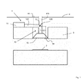
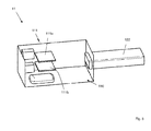
- FIG. 5 One possible construction of the air treatment device 11 is schematic in FIG. 5 shown.
- This air treatment device 11 has in particular a housing 110, as well as a plasma source 111 arranged therein.
- the plasma source 111 comprises two electrodes 111 a, 111 b arranged parallel to one another. Via these electrodes 111 a, 111 b, a DBE is initiated.
- FIG. 5 For better visibility of the interior of the housing 110, the top and the front of the housing 110 are not shown.
- This top and front of the housing 110 may for example consist of a filter, the in turn, as a filter material, for example, may have activated carbon. It is also within the scope of the invention, at least partially, to form further or other sides of the housing 110 through a filter.
- a branch 120 is provided in the air guide 12, a branch 120 is provided.
- the air duct 12 is at this junction of the branch 121, which emanates from the hood 10, in two branches or branches 122, 123 on.
- the branch 122 leads to the air treatment device 11 and the branch 123 passes through the ceiling 4.
- the branch 123 instead of through the ceiling 4 can also pass through the kitchen wall to which the hood 10 is attached, or through another kitchen wall. Outside the room, this branch 123, for example, in an unillustrated exhaust system or a home ventilation system, also not shown.
- the branch 123 thus constitutes an air duct branch in the sense of the present invention.
- sensors 14, 15 are attached to the hood 10 and outside the room, in particular the kitchen.
- the sensor 14 is used, for example, to detect the air condition in the kitchen, while the sensor 15, which is located outside the room, for example, serves to detect the outside temperature.
- the position of the sensors 14, 15 is in the FIG. 1 only indicated schematically. It is also within the scope of the invention, the sensor 14 at a different location in the kitchen, for example, at a different location on the hood 10 or spaced to the hood 10 to order.
- the sensor 15 may be provided, for example, on the outside of the building.
- an air guiding device 13 is arranged in the form of a flap.
- the spoiler 13 is provided at the branch 120.
- branch 122 By pivoting the spoiler 13 can optionally branch 122, which leads to the air treatment device 11 or the branch 123, which leads through the ceiling 4, are closed.
- FIG. 1 shown position of the spoiler 13 is derived from the hood 10 air flow flowing through the branch 121 of the air duct 120, between the branch 122 and the branch 123 divided. The spoiler 13 is thus in a mixing position.
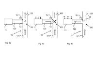
- the different operating conditions or flow conditions of the extractor system at different operating positions of the air guiding device 13 are schematically in the FIGS. 4a to 4c shown.
- the air guiding device 13 is set so that it completely closes the branch 122 to the air treatment device 11 of the extractor system 1.
- the entire air coming from the extractor hood 10 flows via the branch 121 to the branch 120 and is introduced there into the branch 123.
- the air enters an exhaust system or a home ventilation system (both not shown).
- This operating position of the spoiler device which in FIG. 4a is also referred to as Ab effetswolf state and the operating state of the extractor system generated thereby is referred to as Ab effetsschreib.
- the operating state of the extractor system is also referred to as exhaust air operation.
- a home ventilation system is connected, then the operating state of the extractor system is also referred to as recirculation mode or circulation mode.
- FIG. 4b is already in FIG. 1 shown mixed state in which the air flow from the branch 121 of the hood 10 into air streams in the branches 122 and 123 divides.
- the air flow purified in the air treatment device 11 may at least partially exit via the air treatment device 11. This is in FIG. 4b indicated by the block arrows on the air treatment device 11.
- the air preferably exits from this after passing through a filter in the air treatment device 11.
- the filter (not shown) therefore preferably forms part of the wall of the air treatment device 11.
- FIG 4c the air guiding device 13 is shown in a cleaning position.
- the thus set operating state of the extractor system is also referred to as a cleaning state.
- the air guiding device 13 completely closes the branch 123 of the air guide 120, so that the entire air flow guided by the extractor hood 10 into the branch 121 is conducted into the air treatment device 11 where it is treated or treated. From the air treatment device 11, the air can then be returned to the kitchen.
- control unit 16 In the FIGS. 4a to c is also a control unit 16 indicated.
- the control unit 16 may be connected to the sensors 14, 15 and use the received sensor signals to determine a suitable operating position of the air guiding device 13.
- FIG. 2 a second embodiment of the extractor system 1 according to the invention is shown.
- the second embodiment differs from the first embodiment only by the air guide 120.
- the branch 121 which originates from the extractor hood 10, in the already described branch 122 to the air treatment device 11 and a second branch 124 over.
- the branch 124 represents an air duct, which leads to the kitchen and ends there.
- a filter element 125 is provided at the end of the air duct 124. This filter element 125 preferably represents an odor filter.
- only one sensor 14 is provided, via which the air condition in the kitchen can be detected.
- an air guiding device 13 is provided, via which the air flow from the branch 121 is selectively directed into the branch 122 or the branch 124 or partially into each of these two branches 122, 124.
- the entire guided by the cooker hood 10 in the branch 120 air is returned to the kitchen.
- the return takes place either via the air treatment device 11 or via the filter element 125 or both via the air treatment device 11 and via the filter element 125th
- FIG. 3 a third embodiment of the extractor system 1 is shown.
- This embodiment differs from the second embodiment FIG. 2 in that, in addition to the branches 122 and 124, a branch 123 according to the first embodiment of FIG. 1 is provided, which leads out of the room in which the hood 10 is operated.
- an air guiding device 13 is likewise provided at the branch 120. Via the air guiding device 13, the air coming from the branch 121 from the extractor hood 10 can be routed either to the air treatment device 11, to the filter element 125 or into an exhaust air or house ventilation system (not shown) connected to the branch 123.
- mixing states can be set via the air guiding device 13, in which, for example, only part of the air flow from the branch 121 to the air treatment device 11 and another part to the filter element 125 and / or to the exhaust air or home ventilation system (not shown) is directed.
- the invention is not limited to the embodiments shown.
- an air treatment device which is also referred to as an air cleaner unit and, for example, based on dielectric barrier discharge (DBE) works with a cooker hood, which is also referred to as extractor hood combined.
- a spoiler such as a flap
- the air flow either completely in an exhaust system, which is also referred to as exhaust system, a home ventilation system or a filter or similar or without filter back into the room air is passed.
- the air can be passed according to the invention after passing through the air cleaner back into the room air.
- the position of the spoiler, such as the flap is free or adjustable in stages, but can also automatically depending on parameters such as the outdoor and indoor temperature, the relative humidity, the VOC (volatile organic compond) load on indoor air, controlled become.
- An advantage of this invention is that, for example, in winter, the heated room air is not blown into the open and thus reduces the heat loss on the other hand, if necessary, the ventilation can take place outdoors in summer. Another advantage is that air conditioned in the summer does not have to be released outside.
- the extractor system for example, depending on the filter aging or piping, by the controller, in particular by the control by the air deflector, also be optimized in terms of pressure drop and noise.
- an activated carbon filter is used as an odor filter on the hood, existing odors in the air cleaner, for example, reduced from cooking processes instead of being stored and thus can not, as in conventional activated carbon filters escape again.
Landscapes
- Engineering & Computer Science (AREA)
- Chemical & Material Sciences (AREA)
- Combustion & Propulsion (AREA)
- Mechanical Engineering (AREA)
- General Engineering & Computer Science (AREA)
- Filtering Of Dispersed Particles In Gases (AREA)
- Ventilation (AREA)
Abstract
Description
Die Erfindung betrifft ein Dunstabzugssystem und ein Verfahren zum Betreiben eines Dunstabzugssystems.The invention relates to a fume extraction system and a method for operating a fume extraction system.
Zur Reinigung von Luft, die beispielsweise beim Kochen auftritt, ist die Verwendung von Dunstabzugshauben bekannt. Hierbei wird die verunreinigte Luft, die auch als Dünste oder Wrasen bezeichnet wird, in der Regel zum einen über einen Fettfilter und zum anderen über Geruchsfilter gereinigt. Als Geruchsfilter sind beispielsweise Aktivkohlefilterkassetten oder Aktivkohlefiltermatten bekannt, die in dem Gehäuse der Dunstabzugshaube in Strömungsrichtung der Luft vor oder nach dem Gebläse der Dunstabzugshaube angeordnet sind.For the purification of air, which occurs for example when cooking, the use of cooker hoods is known. Here, the contaminated air, which is also referred to as fumes or vapors, usually cleaned on the one hand via a grease filter and the other via odor filter. As odor filter, for example, activated carbon filter cassettes or activated carbon filter mats are known, which are arranged in the housing of the extractor hood in the flow direction of the air before or after the blower of the extractor hood.
Ein Nachteil dieser bekannten Art der Luftreinigung besteht darin, dass die Verunreinigungen, insbesondere die Geruchsstoffe bei einem Aktivkohlefilter lediglich in diesem aufgenommen und gespeichert werden und daher aus dem Aktivkohlefilter wieder austreten können. Zudem ist bei diesen bekannten Dunstabzugshauben nachteilig, dass die gesamte aus dem Gebläse der Dunstabzugshaube austretende Luft über den Geruchsfilter geführt wird und dessen Standzeit daher verringert wird und/oder die aus dem Geruchsfilter austretende Luftqualität verschlechtert wird.A disadvantage of this known type of air purification is that the impurities, in particular the odors in an activated carbon filter are only taken and stored in this and therefore can escape from the activated carbon filter again. Moreover, it is disadvantageous in these known extractor hoods that the entire air emerging from the fan of the extractor hood is passed over the odor filter and its service life is therefore reduced and / or the air quality exiting the odor filter is impaired.
Aufgabe der vorliegenden Erfindung ist es daher, eine Lösung zu schaffen, mittels derer eine gezielte und effiziente Reinigung von Luft, insbesondere Entfernung von Geruchsstoffen aus der Luft erreicht werden kann.Object of the present invention is therefore to provide a solution by means of which a targeted and efficient cleaning of air, in particular removal of odors from the air can be achieved.
Der Erfindung liegt die Erkenntnis zugrunde, dass diese Aufgabe gelöst werden kann, indem die die Dunstabzugshaube verlassende Luft unterschiedlichen Behandlungen unterzogen werden kann.The invention is based on the finding that this object can be achieved by the air leaving the extractor hood can be subjected to different treatments.
Erfindungsgemäß wird diese Aufgabe daher gelöst durch ein Dunstabzugssystem, das eine Dunstabzugshaube und mindestens eine Luftaufbereitungsvorrichtung aufweist. Das Dunstabzugssystem ist dadurch gekennzeichnet, dass die Luftaufbereitungsvorrichtung mit der Dunstabzugshaube über eine Luftführung verbunden ist und mindestens eine Plasmaquelle für die Luftaufbereitung aufweist, das Dunstabzugssystem zwischen der Dunstabzugshaube und der mindestens einen Luftaufbereitungsvorrichtung eine Verzweigung der Luftführung aufweist und im Bereich der Verzweigung zumindest eine Luftleitvorrichtung vorgesehen ist, die in mindestens drei Betriebsstellungen einstellbar ist.According to the invention, this object is therefore achieved by a fume extraction system which has an extractor hood and at least one air treatment device. The extractor hood system is characterized in that the air treatment device is connected to the extractor hood via an air duct and has at least one plasma source for the air treatment, the extractor system between the extractor hood and the at least one air treatment device has a branch of the air duct and at least one air guiding device is provided in the region of the branch, which is adjustable in at least three operating positions.
Die Dunstabzugshaube, die im Folgenden auch als Haube oder Abzug bezeichnet wird, stellt vorzugsweise eine Küchendunstabzugshaube dar. Die Dunstabzugshaube weist ein Gebläse auf, über das Luft, insbesondere Dünste und Wrasen von dem Bereich unterhalb und/oder um die Dunstabzugshaube in diese eingesaugt werden. Das Gebläse wird auch als Lüfter bezeichnet. In der Dunstabzugshaube ist vorzugsweise zumindest ein Fettfilter zur Entfernung von Fett oder anderen Verunreinigungen, wie Wassertropfen, vorgesehen. An der Dunstabzugshaube ist mindestens ein Luftauslass vorgesehen, der als Rohr oder Rohrstutzen an dem Gebläsegehäuse der Dunstabzugshaube ausgestaltet sein kann.The extractor hood, which is also referred to below as a hood or hood, preferably represents a kitchen extractor hood. The extractor hood has a blower, are sucked through the air, in particular steam and vapor from the area below and / or around the extractor hood in this. The fan is also called a fan. In the extractor hood, at least one grease filter is preferably provided for removing grease or other contaminants, such as water droplets. At least one air outlet is provided on the extractor hood, which can be configured as a pipe or pipe socket on the fan housing of the extractor hood.
Als Luftaufbereitungsvorrichtung wird eine Vorrichtung bezeichnet, in der Luft zumindest teilweise aktiv behandelt und gereinigt wird. Die Luftaufbereitungsvorrichtung wird daher auch als Reinigungseinheit oder Luftreiniger bezeichnet. Die Luftaufbereitungsvorrichtung weist hierzu erfindungsgemäß mindestens eine Plasmaquelle auf. Durch Erzeugen eines Plasmas in der Luftaufbereitungsvorrichtung können Geruchsstoffe, die in der Luft enthalten sind, zumindest teilweise zersetzt werden. Die Luftaufbereitungsvorrichtung kann zusätzlich zu der Plasmaquelle auch mindestens einen Filter aufweisen. Dieser Filter dient bei der erfindungsgemäßen Luftaufbereitungsvorrichtung vorwiegend der Aufnahme nicht oder nicht vollständig zersetzter Geruchsstoffe. Zudem können in dem Filter auch reaktive Spezies, wie beispielsweise Ozon, die bei der Behandlung der Luft durch das Plasma auftreten können, aufgenommen werden. Hierdurch kann die Luftaufbereitungsvorrichtung sicher betrieben werden und es ist möglich die in der Luftaufbereitungsvorrichtung behandelte Luft wieder in den Raum, in dem die Dunstabzugshaube betrieben wird, insbesondere in die Küche, zurückzuführen. Der Filter umgibt daher vorzugsweise den Raum, in dem das Plasma erzeugt und die Luft mit dem Plasma behandelt wird, zumindest teilweise. Der Filter, der auch als Geruchsfilter bezeichnet wird, kann beispielsweise Aktivkohle oder andere Adsorbermittel als Filtermaterial aufweisen.An air treatment device is a device in which air is at least partially actively treated and cleaned. The air treatment device is therefore also referred to as a cleaning unit or air cleaner. For this purpose, the air treatment device has at least one plasma source according to the invention. By generating a plasma in the air treatment device, odors contained in the air may be at least partially decomposed. The air treatment device may also have at least one filter in addition to the plasma source. This filter is used in the air treatment device according to the invention predominantly the inclusion of not or not completely decomposed odors. In addition, reactive species, such as ozone, which may be present in the treatment of the air by the plasma, may also be included in the filter. As a result, the air treatment device can be operated safely and it is possible the air treated in the air treatment device back into the room in which the hood is operated, in particular in the kitchen, due. The filter therefore preferably surrounds at least partially the space in which the plasma is generated and the air is treated with the plasma. The filter, which is also referred to as an odor filter, may, for example, have activated carbon or other adsorbent as filter material.
Erfindungsgemäß ist die Luftaufbereitungsvorrichtung mit der Dunstabzugshaube verbunden. Als mit der Dunstabzugshaube verbunden, wird erfindungsgemäß vorzugsweise ein Anschließen an oder Anordnen der Luftaufbereitungsvorrichtung in oder an dem Gehäuse der Dunstabzugshaube, beispielsweise im Kamin der Dunstabzugshaube verstanden. Hierbei ist zwischen der Dunstabzugshaube und der Luftaufbereitungsvorrichtung eine Luftführung vorgesehen.According to the invention, the air treatment device is connected to the extractor hood. When connected to the extractor hood, according to the invention, it is preferable to connect or arrange the air treatment device in FIG or understood on the housing of the hood, for example in the chimney of the hood. In this case, an air duct is provided between the extractor hood and the air treatment device.
Diese Luftführung kann beispielsweise als Rohr, Schlauch oder Kanal vorgesehen sein. Vorzugsweise schließt sich die Luftführung an das Gebläsegehäuse, insbesondere einen Auslassstutzen des Gebläsegehäuses, der Dunstabzugshaube an. Die Verzweigung, die in der Luftführung erfindungsgemäß vorgesehen ist, kann als Abzweigung, Vergabelung oder andersartige Aufteilung der Luftführung ausgestaltet sein.This air duct may be provided for example as a pipe, hose or channel. Preferably, the air guide connects to the blower housing, in particular an outlet of the blower housing, the hood. The branch, which is provided according to the invention in the air duct, can be configured as a branch, bifurcation or other division of the air duct.
Im Bereich der Verzweigung ist zumindest eine Luftleitvorrichtung vorgesehen. Als Luftleitvorrichtung wird insbesondere eine Vorrichtung zur Luftumlenkung oder Luftsperrung bezeichnet. Die Luftleitvorrichtung kann auch als Luftweiche bezeichnet werden. Als in dem Bereich der Verzweigung angeordnet, wird im Sinne dieser Erfindung vorzugsweise eine Anordnung unmittelbar an der Verzweigung oder in Strömungsrichtung nach der Verzweigung in der Nähe der Verzweigung verstanden. Durch diese Anordnung der Luftleitvorrichtung kann die Luftzufuhr zu der Luftaufbereitungsvorrichtung oder dem mindestens einen weiteren Ast, der im Folgenden auch als Zweig bezeichnet wird, der Verzweigung eingestellt werden.In the area of the branch, at least one air guiding device is provided. As air guiding device, in particular a device for air deflection or air blocking is referred to. The spoiler can also be referred to as an air switch. For the purposes of this invention, when arranged in the region of the branch, it is preferable to understand an arrangement directly at the branch or in the flow direction after the branch in the vicinity of the branch. By means of this arrangement of the air guiding device, the air supply to the air treatment device or the at least one further branch, which is also referred to below as the branch, of the branch can be set.
Erfindungsgemäß ist die Luftleitvorrichtung in mindestens drei Betriebsstellungen einstellbar. Als Betriebsstellungen werden hierbei Positionen oder Einstellungen der Luftleitvorrichtung verstanden, in denen diese gehalten werden kann und den Luftstrom somit über zumindest eine gewisse Zeit in verschiedene Richtungen lenkt. Durch die unterschiedlichen Betriebsstellungen der Luftleitvorrichtung werden somit unterschiedliche Betriebszustände des Dunstabzugssystem eingestellt. Die Luftleitvorrichtung kann Rastelemente oder andere Fixierelement, wie beispielsweise Anschläge aufweisen, die die Luftleitvorrichtung in den mindestens drei Betriebsstellungen halten können.According to the invention, the spoiler device can be adjusted in at least three operating positions. In this case, positions or settings of the air guiding device are understood to mean operating positions in which these can be held and thus direct the air flow in different directions over at least a certain time. Due to the different operating positions of the spoiler different operating conditions of the extractor system are thus set. The spoiler device may have locking elements or other fixing element, such as stops, which can hold the spoiler in the at least three operating positions.
Die drei Betriebsstellungen der Luftleitvorrichtung, die vorzugsweise eingestellt werden können, sind insbesondere als Reinigungsstellung, Ableitungsstellung und Mischstellung bezeichnet. Ist die Luftleitvorrichtung auf die Reinigungsstellung eingestellt, so wird vorzugsweise der gesamte aus der Dunstabzugshaube austretende Luftstrom zu der Luftaufbereitungsvorrichtung geleitet und dort gereinigt, das heißt insbesondere von Geruchsstoffen befreit. Von der Luftaufbereitungsvorrichtung kann der so gereinigte Luftstrom wieder in den Raum, in dem die Dunstabzugshaube betrieben wird, zurückgeleitet werden. Bei der Reinigungsstellung der Luftleitvorrichtung wird der an dem Dunstabzugssystem eingestellte Betriebszustand als Reinigungszustand oder Reinigungsbetrieb bezeichnet.The three operating positions of the spoiler device, which can preferably be adjusted, are designated in particular as a cleaning position, discharge position and mixing position. If the air-guiding device is set to the cleaning position, preferably the entire air flow emerging from the extractor hood is conducted to the air-conditioning device and cleaned there, that is to say especially freed of odors. From the air treatment device, the cleaned air flow back into the room in which the hood is operated, be returned. In the cleaning position of the air guiding device, the operating state set on the extractor system is referred to as a cleaning state or a cleaning operation.
Bei der Ableitungsstellung der Luftleitvorrichtung wird vorzugsweise der gesamte aus der Dunstabzugshaube austretende Luftstrom an der Luftaufbereitungsvorrichtung vorbeigeleitet, das heißt erreicht die Luftaufbereitungsvorrichtung nicht. Bei dieser Stellung der Luftleitvorrichtung wird an dem Dunstabzugssystem ein Ableitungsbetrieb eingestellt. Dieser kann ein Umluftbetrieb oder ein Abluftbetrieb sein. Bei einem Umluftbetrieb wird die Luft nach dem Passieren der Luftleitvorrichtung an eine Luftleitung geleitet, die beispielsweise über eine Hausbelüftungsanlage in einen anderen Raum oder unmittelbar wieder in den Raum, in dem die Dunstabzugshaube des Dunstabzugssystems betrieben wird, führt. Bei einem Abluftbetrieb wird die Luft nach dem Passieren der Luftleitvorrichtung an eine Luftleitung geleitet, die beispielsweise ein Abluftrohr oder Abluftsystem darstellen kann und in die Umgebung, das heißt nach außen führt.In the discharge position of the air guiding device, the entire air flow emerging from the extractor hood is preferably conducted past the air treatment device, that is to say it does not reach the air treatment device. In this position of the spoiler, a discharge operation is set to the extractor system. This can be a recirculation mode or an exhaust air mode. In a circulating air operation, the air is passed after passing the spoiler to an air line, which leads, for example via a home ventilation system in another room or directly back into the room in which the hood of the extractor system is operated. In an exhaust air operation, the air is passed after passing the air guide to an air line, which may for example represent an exhaust pipe or exhaust air system and into the environment, that leads to the outside.
Bei der Mischstellung wird ein Mischzustand oder Mischbetrieb des Dunstabzugssystems, der eine Mischung aus Reinigungsbetrieb und Ableitungsbetrieb, das heißt Umluft- oder Abluftbetrieb, darstellt, eingestellt. Hierbei wird vorzugsweise ein Teil des aus der Dunstabzugshaube austretenden Luftstroms zu der Luftaufbereitungsvorrichtung und ein weiterer Teil an der Luftaufbereitungsvorrichtung vorbei zu mindestens einer Luftleitung und von dort entweder in den Raum oder in die Umgebung geleitet.In the mixing position, a mixing state or mixing operation of the extractor system, which is a mixture of cleaning operation and discharge operation, that is, recirculation or exhaust air operation, is set. In this case, a part of the air flow exiting the extractor hood is preferably conducted to the air treatment device and another part is routed past the air treatment device to at least one air line and from there either into the room or into the environment.
Der Vorteil des erfindungsgemäßen Dunstabzugssystems besteht darin, dass die Luft, die von der Dunstabzugshaube angesaugt und gegebenenfalls in dieser bereits von Verunreinigungen, wie Fett- und/oder Flüssigkeitspartikeln, befreit wurde, gezielt und effizient gereinigt werden kann und insbesondere Geruchsstoffe aus der Luft entfernt werden können. Die Effizienz wird bei dem erfindungsgemäßen Dunstabzugssystem insbesondere dadurch erreicht, dass die Luftzufuhr zu einer Luftaufbereitungsvorrichtung oder anderen Komponenten gezielt eingestellt und den Umgebungsbedingungen angepasst werden kann. Schließlich wird durch die Verwendung einer Luftaufbereitungsvorrichtung mit einer Plasmaquelle auch ein Zerstören oder Zersetzen der Geruchsstoffe erzielt, das gegenüber dem reinen Abscheiden der Geruchsstoffe in bekannten Filtern von Vorteil ist, da ein Austreten der Geruchsstoffe aus der Luftaufbereitungsvorrichtung weitestgehend verhindert werden kann.The advantage of the extractor system according to the invention is that the air that has been sucked in from the extractor hood and optionally already freed from contaminants, such as fat and / or liquid particles, can be cleaned in a targeted and efficient manner and, in particular, odors are removed from the air can. The efficiency is achieved in the extractor hood system according to the invention in particular by the fact that the air supply to an air treatment device or other components can be adjusted specifically and adapted to the ambient conditions. Finally, the use of an air treatment device with a plasma source also destroys or decomposing the odors, which is advantageous over the pure separation of the odors in known filters, since leakage of the odors from the air treatment device can be largely prevented.
Gemäß einer bevorzugten Ausführungsform weist die Plasmaquelle der Luftaufbereitungsvorrichtung Mittel zur Erzeugung einer dielektrischen Barriereentladung, insbesondere mindestens zwei Elektroden, auf. Diese Art der Plasmaerzeugung wird auch als DBE bezeichnet. Als DBE wird insbesondere die elektrische Entladung zwischen zwei Elektroden bezeichnet, die durch eine isolierende dielektrische Barriere voneinander getrennt sind. Erfindungsgemäß kann zwischen den Elektroden Luft vorliegen und insbesondere die zu behandelnde Luft zwischen den Elektroden hindurchströmen. Hierdurch vereinfacht sich der Aufbau der Luftaufbereitungsvorrichtung und zudem kann eine gute Durchmischung der in der Luftaufbereitungsvorrichtung zu behandelnden Luft erzielt werden. Durch die DBE wird ein Plasma erzeugt, mittels dessen die in die Luftaufbereitungsvorrichtung gelangende Luft mit hoher Energie beaufschlagt wird und dadurch behandelt wird. Insbesondere werden in der Luft enthaltene Geruchsstoffe zersetzt. Indem die Luftleitvorrichtung des erfindungsgemäßen Dunstabzugssystem in mindestens drei Betriebsstellungen einstellbar ist, kann auch bei Ableitung eines Teils des Luftstroms in einen Ast der Luftführung, der nicht mit der Luftaufbereitungsvorrichtung verbunden ist, weiterhin eine gewisse Luftzufuhr zu der Luftaufbereitungsvorrichtung gewährleistet werden. Dieser Zustand wird auch als Mischzustand bezeichnet. Durch die Möglichkeit der Einstellung dieses Zustandes kann ein Austreten von reaktiven Spezies, wie beispielsweise Ozon, die in der Luftaufbereitungsvorrichtung gebildet werden, verhindert werden, ohne die Zufuhr zu der Luftaufbereitungsvorrichtung vollständig verschließen zu müssen.According to a preferred embodiment, the plasma source of the air treatment device comprises means for generating a dielectric barrier discharge, in particular at least two electrodes. This type of plasma generation is also referred to as DBE. DBE is in particular the electrical discharge between two electrodes, which are separated by an insulating dielectric barrier. According to the invention, air can be present between the electrodes and, in particular, the air to be treated can flow between the electrodes. This simplifies the construction of the air treatment device and, moreover, good mixing of the air to be treated in the air treatment device can be achieved. The DBE generates a plasma, by means of which the air entering the air treatment device is subjected to high energy and is thus treated. In particular, odors contained in the air are decomposed. By the air deflector of the extractor system according to the invention is adjustable in at least three operating positions, even with the discharge of a portion of the air flow in a branch of the air duct, which is not connected to the air treatment device, a certain air supply to the air treatment device can continue to be ensured. This condition is also called mixed state. By being able to adjust this condition, leakage of reactive species such as ozone formed in the air conditioning apparatus can be prevented without having to completely close the supply to the air treatment apparatus.
Gemäß einer Ausführungsform stellt die Luftaufbereitungsvorrichtung eine zu der Dunstabzugshaube separate Vorrichtung dar, die über die Luftführung mit der Dunstabzugshaube verbunden ist.According to one embodiment, the air treatment device is a separate device to the hood, which is connected via the air duct with the extractor hood.
Die Verbindung kann, wie oben beschrieben über Kanäle oder Rohre erfolgen. Die separate Ausführung der Luftaufbereitungsvorrichtung weist eine Reihe von Vorteilen auf. Zum einen kann die Luftaufbereitungsvorrichtung auch nachträglich zum Betrieb mit der Dunstabzugshaube vorgesehen werden. Zum anderen können die Abmessungen der Luftaufbereitungsvorrichtung entsprechend der Funktionen der Luftaufbereitungsvorrichtung gewählt werden und müssen nicht zwangsweise auf die Abmessungen der Dunstabzugshaube angepasst werden. Es ist erfindungsgemäß aber auch möglich, die Luftaufbereitungsvorrichtung in der Dunstabzugshaube zu integrieren. Hierbei wird die Luftaufbereitungsvorrichtung vorzugsweise in einem Gehäuse der Dunstabzugsvorrichtung vorgesehen, beispielsweise in einem Kamin oder Kanal der Dunstabzugshaube aufgenommen.The connection can be made via channels or pipes as described above. The separate embodiment of the air treatment device has a number of advantages. On the one hand, the air treatment device can also be provided subsequently for operation with the extractor hood. On the other hand, the Dimensions of the air treatment device are selected according to the functions of the air treatment device and do not necessarily have to be adapted to the dimensions of the extractor hood. However, it is also possible according to the invention to integrate the air treatment device in the extractor hood. In this case, the air treatment device is preferably provided in a housing of the extractor device, for example, received in a chimney or duct of the extractor hood.
Vorzugsweise weist die Verzweigung der Luftführung zumindest drei Äste auf, wobei einer der Äste mit der Dunstabzugshaube, einer der Äste mit der Luftaufbereitungsvorrichtung und einer der Äste mit einer Luftleitung verbunden ist. Der Ast, der mit der Luftleitung verbunden ist, kann erfindungsgemäß auch selber die Luftleitung darstellen. Als Luftleitung wird hierbei ein System bezeichnet, über das Luft in die Umgebung und/oder in den Raum, in dem die Dunstabzugshaube betrieben wird, oder in einen anderen Raum abgegeben werden kann. Die Luftleitung kann daher nach Außen führen, das heißt die Luft wird außerhalb des Gebäudes abgegeben. Im Sinne der Erfindung kann die Luftleitung aber auch eine Hausbelüftungsanlage darstellen. Weiterhin kann die Luftleitung auch in den Raum, in dem die Dunstabzugshaube betrieben wird, führen.Preferably, the branch of the air duct has at least three branches, wherein one of the branches is connected to the extractor hood, one of the branches to the air treatment device and one of the branches to an air line. The branch, which is connected to the air line, according to the invention can also represent the air line itself. An air duct is hereby referred to a system by means of which air can be discharged into the environment and / or into the room in which the extractor hood is operated or into another room. The air line can therefore lead to the outside, that is, the air is discharged outside the building. For the purposes of the invention, however, the air line can also be a house ventilation system. Furthermore, the air line can also lead into the room in which the hood is operated.
Über den Ast, der mit der Dunstabzugshaube verbunden ist, wird die Luft von der Dunstabzugshaube weggeführt. Indem bei der bevorzugten Ausführungsform mindestens zwei weitere Äste in der Luftführung vorgesehen sind, kann die Luft, je nach den Umgebungsbedingungen oder den Bedingungen der Komponenten des Dunstabzugssystems in die entsprechenden Äste der Luftführung geleitet werden. Somit kann beispielsweise die Menge an Luft, die zu der Luftaufbereitungsvorrichtung geleitete wird, minimiert werden. Dies führt dazu, dass die Luftaufbereitungsvorrichtung weniger beansprucht wird und deren Standzeit somit erhöht werden kann. Ist der weitere Ast der Luftführung mit einer Luftleitung verbunden, an die sich eine Abluftanlage oder Abluftleitung anschließt, so kann beispielsweise Luft mit einem hohen Verunreinigungsgrad aus dem Gebäude herausgeführt werden anstatt diesen über die Luftaufbereitungsvorrichtung zu leiten. Auch die Temperaturen in dem Raum, in dem die Dunstabzugshaube betrieben wird, und der Umgebung können berücksichtigt werden. So kann beispielsweise im Winter die Luft stets in den Raum, in dem die Dunstabzugshaube betrieben wird, zurückgeführt werden. Diese Rückführung kann über die Luftaufbereitungsvorrichtung oder über eine Luftleitung, die als Umluftleitung bezeichnet wird, erfolgen. Hierdurch kann Energie eingespart werden, da die geheizte Raumluft wieder dem Raum zugeführt wird. Im Sommer hingegen kann das Dunstabzugssystem zur Belüftung des Raumes verwendet werden, indem die Luft in die Umgebung abgegeben wird.About the branch, which is connected to the hood, the air is led away from the hood. By providing in the preferred embodiment, at least two other branches in the air duct, the air, depending on the ambient conditions or the conditions of the components of the extractor system can be passed into the corresponding branches of the air duct. Thus, for example, the amount of air that is directed to the air conditioning device can be minimized. As a result, the air treatment device is less stressed and its service life can thus be increased. If the further branch of the air duct is connected to an air line, which is followed by an exhaust air system or exhaust air duct, for example, air with a high degree of contamination can be led out of the building instead of passing it via the air treatment device. Also, the temperatures in the room in which the hood is operated, and the environment can be considered. For example, in winter, the air can always be returned to the room where the cooker hood is operated. This recirculation may be via the air treatment device or via an air line, which is referred to as recirculation line, done. This energy can be saved because the heated room air is returned to the room. In summer, on the other hand, the extractor system can be used to ventilate the room by releasing the air into the environment.
Vorzugsweise ist in der Luftleitung, die mit einem der Äste der Verzweigung verbunden ist oder diesen darstellt, zumindest ein Filterelement angeordnet. Dieses Filterelement stellt vorzugsweise einen Geruchsfilter dar, der beispielsweise ein Aktivkohlefilter sein kann. Das Filterelement ist insbesondere bevorzugt in den Fällen vorgesehen, in denen die Luftleitung zu dem Raum, in dem die Dunstabzugshaube betrieben wird, zurückführt. Das Filterelement ist daher bei einer Umluftleitung oder einer Hausbelüftungsanlage vorzugsweise vorgesehen. Hierbei kann das Filterelement in der Nähe der Verzweigung oder aber auch an einem anderen Ort, insbesondere kurz vor dem Austritt der Luftleitung in den Raum, in dem die Dunstabzugshaube betrieben wird, oder in einen anderen Raum angeordnet sein.Preferably, at least one filter element is arranged in the air line which is connected to or represents one of the branches of the branch. This filter element preferably represents an odor filter, which may be, for example, an activated carbon filter. The filter element is particularly preferably provided in the cases in which the air line leads back to the room in which the extractor hood is operated. The filter element is therefore preferably provided in a recirculation line or a house ventilation system. In this case, the filter element in the vicinity of the branch or even at a different location, in particular just before the exit of the air duct in the room in which the hood is operated, or be arranged in another room.
Gemäß einer Ausführungsform stellt die Luftleitvorrichtung eine Klappe dar. Diese Ausführungsform ist besonders einfach im Aufbau und in der Handhabung. Die Klappe kann hierbei an der Verzweigung so vorgesehen sein, dass diese je nach der eingestellten Position oder Stellung zumindest einen Teil des Querschnitts einer der Äste, die von der Verzweigung abgehen, abdeckt. Alternativ ist es aber auch möglich eine Klappe in zumindest einem der von der Verzweigung abgehenden Äste vorzusehen. Hierdurch kann die Einstellung noch genauer erfolgen. Es sind aber auch andere Luftleitvorrichtungen möglich, die den Querschnitt zumindest eines der von der Verzweigung abgehenden Äste zumindest zeitweise verringert.According to one embodiment, the spoiler device is a flap. This embodiment is particularly simple in construction and handling. The flap may in this case be provided at the junction so that it covers at least a part of the cross section of one of the branches, which depart from the branch, depending on the set position or position. Alternatively, it is also possible to provide a flap in at least one of the branches leaving the branch. As a result, the setting can be made even more accurate. However, other air guiding devices are also possible which at least temporarily reduce the cross section of at least one of the branch branches.
Gemäß einer Ausführungsform ist die Luftleitvorrichtung stufenlos in unterschiedliche Positionen oder Stellungen einstellbar. Bei dieser Ausführungsform können somit mehr als drei Betriebsstellungen der Luftleitvorrichtung eingestellt werden. Der Reinigungszustand und der Ableitungszustand sind hierbei weiterhin in den möglichen Zuständen enthalten. Weiterhin kann aber eine Reihe von Mischzuständen eingestellt werden. Dies ist vorteilhaft, da hierdurch eine weitere Steigerung der Effizienz möglich ist. Der Antrieb der Luftleitvorrichtung und deren Fixierung in den unterschiedlichen Zuständen kann bei dieser Ausführungsform besonders vorteilhaft durch einen Motor erfolgen.According to one embodiment, the air guiding device is infinitely adjustable in different positions or positions. In this embodiment, thus more than three operating positions of the spoiler device can be adjusted. The cleaning state and the derivative state are still included in the possible states. Furthermore, however, a number of mixed states can be set. This is advantageous because it allows a further increase in efficiency. The drive of the spoiler device and its fixation in the different states can be done particularly advantageous in this embodiment by a motor.
Gemäß einer Ausführungsform ist Luftleitvorrichtung mit zumindest einem Sensor, insbesondere einem Sensor zur Bestimmung des Luftzustandes, verbunden. Als Luftzustand wird hierbei beispielsweise die Temperatur in dem Raum, in dem die Dunstabzugshaube betrieben wird, die Außentemperatur, die Differenz zwischen diesen beiden Temperaturen, die Luftfeuchtigkeit und/oder die Beladung der Innenluft mit Verunreinigungen (beispielsweise VOC (volatile organic compounds)) bezeichnet. Indem diese Luftzustände über den Sensor oder die Sensoren ermittelt werden, können die ermittelten Werte dann als Parameter zur automatischen Einstellung der Betriebsstellung der Luftleitvorrichtung dienen.According to one embodiment, the air guiding device is connected to at least one sensor, in particular a sensor for determining the air condition. In this case, for example, the temperature in the room in which the extractor hood is operated, the outside temperature, the difference between these two temperatures, the air humidity and / or the loading of the inside air with impurities (for example VOC (volatile organic compounds)) are referred to as the air condition. By determining these air states via the sensor or the sensors, the determined values can then serve as parameters for the automatic adjustment of the operating position of the air guiding device.
Gemäß einer Ausführungsform weist das Dunstabzugssystem eine Steuereinheit zur Steuerung der zumindest einen Luftleitvorrichtung auf. Mittels der Steuerung kann die Luftleitvorrichtung in die unterschiedlichen Betriebsstellungen gebracht und gegebenenfalls auch dort gehalten werden. Zusätzlich kann die Steuereinheit dazu dienen die einzustellende Betriebsstellung der Luftleitvorrichtung zu bestimmen. Hierzu kann die Steuereinheit beispielsweise mit Sensoren verbunden sein. Mittel dieser Sensoren kann dann der Luftzustand ermittelt werden und daraus der über die Luftleitvorrichtung einzustellende geeignete Betriebszustand des Dunstabzugssystems bestimmt werden. Die Ansteuerung der Luftleitvorrichtung(en) erfolgt hierbei vorzugsweise automatisch, beispielsweise über einen oder mehrere Motoren.According to one embodiment, the extractor system has a control unit for controlling the at least one air guiding device. By means of the controller, the spoiler device can be brought into the different operating positions and optionally also held there. In addition, the control unit can serve to determine the operating position of the air guiding device to be set. For this purpose, the control unit may be connected to sensors, for example. By means of these sensors, the air state can then be determined and from this the suitable operating state of the extractor system to be set via the air guiding device can be determined. The control of the spoiler device (s) is preferably carried out automatically, for example via one or more motors.
Gemäß einem weiteren Aspekt betrifft die Erfindung ein Verfahren zum Betreiben eines erfindungsgemäßen Dunstabzugssystems. Das Verfahren ist dadurch gekennzeichnet, dass durch die Luftleitvorrichtung mindestens einer von mindestens drei Betriebszuständen des Dunstabzugssystems eingestellt wird. Gemäß einer bevorzugten Ausführungsform wird die Luftleitvorrichtung in Abhängigkeit von mindestens einer Zustandsgröße des Luftzustandes gesteuert.According to a further aspect, the invention relates to a method for operating a fume extraction system according to the invention. The method is characterized in that at least one of at least three operating states of the extractor system is set by the air guiding device. According to a preferred embodiment, the air guiding device is controlled as a function of at least one state variable of the air condition.
Vorteile und Merkmale, die bezüglich des erfindungsgemäßen Dunstabzugssystems beschrieben werden, gelten - soweit anwendbar - entsprechend für das erfindungsgemäße Verfahren und umgekehrt und werden daher gegebenenfalls nur einmal erläutert.Advantages and features which are described with regard to the extractor system according to the invention apply - as far as applicable - accordingly for the method according to the invention and vice versa and are therefore possibly only explained once.
Die Erfindung wird im Folgenden erneut unter Bezugnahme auf die beiliegenden Zeichnungen erläutert. Hierbei zeigen:
-
Figur 1 : eine schematische Darstellung einer ersten Ausführungsform des erfindungsgemäßen Dunstabzugssystems; -
Figur 2 : eine schematische Darstellung einer zweiten Ausführungsform des erfindungsgemäßen Dunstabzugssystems; -
Figur 3 : eine schematische Darstellung einer dritten Ausführungsform des erfindungsgemäßen Dunstabzugssystems; -
Figuren 4 a bis 4c : schematische Darstellungen von drei Betriebszuständen der Luftleitvorrichtung in der ersten Ausführungsform des erfindungsgemäßen Dunstabzugssystems; und -
Figur 5 : eine schematische, perspektivische Darstellung einer Ausführungsform einer Luftaufbereitungsvorrichtung des erfindungsgemäßen Dunstabzugssystems.
-
FIG. 1 a schematic representation of a first embodiment of the extractor system according to the invention; -
FIG. 2 a schematic representation of a second embodiment of the extractor system according to the invention; -
FIG. 3 a schematic representation of a third embodiment of the extractor system according to the invention; -
FIGS. 4 a to 4 c : schematic representations of three operating states of the spoiler device in the first embodiment of the extractor system according to the invention; and -
FIG. 5 : A schematic, perspective view of an embodiment of an air treatment device of the extractor system according to the invention.
In
Ein möglicher Aufbau der Luftaufbereitungsvorrichtung 11 ist schematische in
In der Luftführung 12 ist eine Verzweigung 120 vorgesehen. In der ersten Ausführungsform des Dunstabzugssystems 1 geht die Luftführung 12 an dieser Verzweigung von dem Ast 121, der von der Dunstabzugshaube 10 ausgeht, in zwei Abzweigungen oder Äste 122, 123 über. Der Ast 122 führt zu der Luftaufbereitungsvorrichtung 11 und der Ast 123 führt durch die Raumdecke 4 hindurch. Es versteht sich, dass der Ast 123 statt durch die Raumdecke 4 auch durch die Küchenwand, an der die Dunstabzugshaube 10 befestigt ist, oder durch eine andere Küchenwand hindurchführen kann. Außerhalb des Raumes geht dieser Ast 123 beispielsweise in eine nicht dargestellte Abluftanlage oder eine ebenfalls nicht dargestellte Hausbelüftungsanlage über. Der Ast 123 stellt somit einen Luftleitungsast im Sinne der vorliegenden Erfindung dar.In the
Wie sich aus
In der Luftführung 120 ist eine Luftleitvorrichtung 13 in Form einer Klappe angeordnet. In der dargestellten Ausführungsform ist die Luftleitvorrichtung 13 an der Verzweigung 120 vorgesehen. Durch Verschwenken der Luftleitvorrichtung 13 kann wahlweise der Ast 122, der zu der Luftaufbereitungsvorrichtung 11 führt oder der Ast 123, der durch die Raumdecke 4 führt, verschlossen werden. In der in
Die unterschiedlichen Betriebszustände oder Strömungsverhältnisse des Dunstabzugssystems bei unterschiedlichen Betriebsstellungen der Luftleitvorrichtung 13 sind schematisch in den
In der
In
In
In den
In
Bei der zweiten Ausführungsform ist lediglich ein Sensor 14 vorgesehen, über den der Luftzustand in der Küche erfasst werden kann.In the second embodiment, only one
Bei der zweiten Ausführungsform ist, wie bei der ersten Ausführungsform des Dunstabzugssystems 1 eine Luftleitvorrichtung 13 vorgesehen, über die der Luftstrom aus dem Ast 121 wahlweise in den Ast 122 oder den Ast 124 oder teilweise in jeden dieser beiden Aste 122, 124 geleitet wird. Bei dieser Ausführungsform wird daher die gesamte von der Dunstabzugshaube 10 in dem Ast 120 geleitete Luft wieder in die Küche zurückgeführt. Hierbei erfolgt die Rückführung entweder über die Luftaufbereitungsvorrichtung 11 oder über das Filterelement 125 oder sowohl über die Luftaufbereitungsvorrichtung 11 als auch über das Filterelement 125.In the second embodiment, as in the first embodiment of the
In
Die Erfindung ist nicht auf die gezeigten Ausführungsformen beschränkt. Beispielsweise ist es auch möglich die Luftführung und die Luftaufbereitungsvorrichtung in dem Gehäuse der Dunstabzugshaube vorzusehen. Zudem sind andere Ausführungsformen der Luftaufbereitungsvorrichtung als die in
Mit der vorliegenden Erfindung können die Anforderungen an die Luftführung in einem Dunstabzugssystem, das eine Dunstabzugshaube und eine Luftaufbereitungsvorrichtung umfasst, geeignet eingestellt werden. Hierzu wird eine Luftaufbereitungsvorrichtung, die auch als Luftreinigereinheit bezeichnet wird und beispielsweise basierend auf dielektrischer Barriereentladung (DBE) arbeitet mit einer Dunstabzugshaube, die auch als Dunstabzug bezeichnet wird, kombiniert. In der Luftstrecke, die auch als Luftführung bezeichnet wird, zwischen dem Luftreiniger und dem Dunstabzug befindet sich eine Luftleitvorrichtung, beispielsweise eine Klappe, mit deren Hilfe der Luftstrom entweder vollständig in eine Abluftanlage, die auch als Abluftsystem bezeichnet wird, eine Hausbelüftungsanlage oder über einen Filter oder Ähnliches oder auch ohne Filter zurück in die Raumluft geleitet wird. Die Luft kann erfindungsgemäß nach Passieren des Luftreinigers zurück in die Raumluft geleitet werden. Die Stellung der Luftleitvorrichtung, beispielsweise der Klappe, ist frei oder in Stufen eintstellbar, kann aber auch automatisch in Abhängigkeit von Parametern wie zum Beispiel der Außen- und Innentemperatur, der relativen Luftfeuchtigkeit, der VOC (volatile organic compond)-Belastung der Innenraumluft, gesteuert werden.With the present invention, the requirements for the air duct in an extractor system comprising a cooker hood and an air treatment device can be suitably adjusted. For this purpose, an air treatment device, which is also referred to as an air cleaner unit and, for example, based on dielectric barrier discharge (DBE) works with a cooker hood, which is also referred to as extractor hood combined. In the air gap, which is also referred to as air duct between the air cleaner and the extractor is a spoiler, such as a flap, with the help of the air flow either completely in an exhaust system, which is also referred to as exhaust system, a home ventilation system or a filter or similar or without filter back into the room air is passed. The air can be passed according to the invention after passing through the air cleaner back into the room air. The position of the spoiler, such as the flap, is free or adjustable in stages, but can also automatically depending on parameters such as the outdoor and indoor temperature, the relative humidity, the VOC (volatile organic compond) load on indoor air, controlled become.
Ein Vorteil dieser Erfindung besteht darin, dass beispielsweise im Winter die beheizte Raumluft nicht ins Freie geblasen wird und somit der Wärmeverlust reduziert wird, hingegen im Sommer bei Bedarf die Lüftung ins Freie erfolgen kann. Ein weiterer Vorteil ist, dass im Sommer klimatisierte Luft nicht ins Freie abgegeben werden muss. Zudem kann das Dunstabzugssystem, zum Beispiel in Abhängigkeit der Filteralterung oder der Verrohrung, durch die Steuerung, insbesondere durch die Steuerung durch die Luftleitvorrichtung, auch hinsichtlich des Druckabfalls und Geräuschentwicklung optimiert werden. Im Gegensatz zu herkömmlichen Dunstabzugssystemen, bei denen statt einer Luftaufbereitungsvorrichtung ein Aktivkohlefilter als Geruchsfilter an der Dunstabzugshaube verwendet wird, werden zudem vorhandene Gerüche im Luftreiniger beispielsweise aus Kochvorgängen abgebaut anstatt gespeichert zu werden und können somit nicht, wie beispielsweise bei herkömmlichen Aktivkohlefiltern wieder austreten.An advantage of this invention is that, for example, in winter, the heated room air is not blown into the open and thus reduces the heat loss on the other hand, if necessary, the ventilation can take place outdoors in summer. Another advantage is that air conditioned in the summer does not have to be released outside. In addition, the extractor system, for example, depending on the filter aging or piping, by the controller, in particular by the control by the air deflector, also be optimized in terms of pressure drop and noise. In contrast to conventional extractor systems, in which instead of an air treatment device, an activated carbon filter is used as an odor filter on the hood, existing odors in the air cleaner, for example, reduced from cooking processes instead of being stored and thus can not, as in conventional activated carbon filters escape again.
- 11
- DunstabzugssystemExtractor system
- 1010
- DunstabzugshaubeHood
- 1111
- LuftaufbereitungsvorrichtungAir conditioning device
- 110110
- Gehäusecasing
- 111111
- Plasmaquelleplasma source
- 111 a111 a
- Elektrodeelectrode
- 111111
- b Elektrodeb electrode
- 1212
- Luftführungair duct
- 120120
- Verzweigungbranch
- 121121
- Astbranch
- 122122
- Astbranch
- 123123
- Astbranch
- 124124
- Astbranch
- 125125
- Filterelementfilter element
- 1313
- Luftleitvorrichtungspoiler device
- 1414
- Sensorsensor
- 1515
- Sensorsensor
- 1616
- Steuereinheitcontrol unit
- 22
- Kochfeldhob
- 33
- OberschrankWall unit
- 44
- Raumdeckeceiling
Claims (11)
Applications Claiming Priority (1)
| Application Number | Priority Date | Filing Date | Title |
|---|---|---|---|
| DE102011082928A DE102011082928A1 (en) | 2011-09-19 | 2011-09-19 | Extractor system and method for operating a fume extraction system |
Publications (2)
| Publication Number | Publication Date |
|---|---|
| EP2570735A1 true EP2570735A1 (en) | 2013-03-20 |
| EP2570735B1 EP2570735B1 (en) | 2019-06-26 |
Family
ID=46758685
Family Applications (1)
| Application Number | Title | Priority Date | Filing Date |
|---|---|---|---|
| EP12183183.8A Not-in-force EP2570735B1 (en) | 2011-09-19 | 2012-09-05 | Vapour extractor system and method for operating same |
Country Status (3)
| Country | Link |
|---|---|
| EP (1) | EP2570735B1 (en) |
| DE (1) | DE102011082928A1 (en) |
| DK (1) | DK2570735T3 (en) |
Cited By (5)
| Publication number | Priority date | Publication date | Assignee | Title |
|---|---|---|---|---|
| EP2789921A1 (en) * | 2013-04-09 | 2014-10-15 | Silverline Küchengeräte und Handel GmbH | Extractor hood |
| WO2017140554A1 (en) * | 2016-02-15 | 2017-08-24 | Bruckbauer, Wilhelm | Device for arranging one or more electrodes of a plasma filter in a housing of a fume hood apparatus |
| CN108087939A (en) * | 2018-01-23 | 2018-05-29 | 武汉浩航环保科技有限公司 | A kind of disc type soot dust granule object seperator |
| CN108826407A (en) * | 2018-07-20 | 2018-11-16 | 广东美的厨房电器制造有限公司 | Ceiling mounting type smoke machine |
| EP3667176A1 (en) * | 2018-12-11 | 2020-06-17 | Franke Futurum AB | Fume extractor hood, method for operating a fume extractor hood |
Families Citing this family (6)
| Publication number | Priority date | Publication date | Assignee | Title |
|---|---|---|---|---|
| EP2937633A1 (en) | 2014-04-22 | 2015-10-28 | E.G.O. ELEKTRO-GERÄTEBAU GmbH | Device for purifying air, ventilation device and method of air purification |
| DE102019121115A1 (en) | 2019-08-05 | 2021-02-11 | Miele & Cie. Kg | Air treatment system for improving an air quality of indoor air in a room and method for its operation |
| CN113251455B (en) * | 2021-07-07 | 2022-03-04 | 南京德力通环境科技有限公司 | Civil integrated oil fume purification and collection all-in-one machine and purification method thereof |
| DE102021132344B4 (en) | 2021-12-08 | 2024-09-26 | Naber Holding Gmbh & Co. Kg | Method for switching a ventilation unit and a corresponding ventilation unit |
| NL2033133B1 (en) * | 2022-09-26 | 2024-04-03 | Bos Fornuizen B V | Extractor assembly for a household stove, stove arrangement, and working method |
| DE102023200817A1 (en) | 2023-02-01 | 2024-08-01 | BSH Hausgeräte GmbH | Control of an extractor hood |
Citations (1)
| Publication number | Priority date | Publication date | Assignee | Title |
|---|---|---|---|---|
| DE102008009202A1 (en) * | 2008-02-15 | 2009-08-20 | BSH Bosch und Siemens Hausgeräte GmbH | Extractor system with separate filter housing |
Family Cites Families (1)
| Publication number | Priority date | Publication date | Assignee | Title |
|---|---|---|---|---|
| DE3040051A1 (en) * | 1980-10-23 | 1982-06-03 | Georg Röhl, Lichttechnische Spezialfabrik, Apparate- und Gerätebau GmbH & Co KG, 8400 Regensburg | Vapour exhaust hood control system - involves control of exhaust and fresh air ratio by regulating blower volume and/or speed |
-
2011
- 2011-09-19 DE DE102011082928A patent/DE102011082928A1/en not_active Withdrawn
-
2012
- 2012-09-05 EP EP12183183.8A patent/EP2570735B1/en not_active Not-in-force
- 2012-09-05 DK DK12183183.8T patent/DK2570735T3/en active
Patent Citations (1)
| Publication number | Priority date | Publication date | Assignee | Title |
|---|---|---|---|---|
| DE102008009202A1 (en) * | 2008-02-15 | 2009-08-20 | BSH Bosch und Siemens Hausgeräte GmbH | Extractor system with separate filter housing |
Cited By (5)
| Publication number | Priority date | Publication date | Assignee | Title |
|---|---|---|---|---|
| EP2789921A1 (en) * | 2013-04-09 | 2014-10-15 | Silverline Küchengeräte und Handel GmbH | Extractor hood |
| WO2017140554A1 (en) * | 2016-02-15 | 2017-08-24 | Bruckbauer, Wilhelm | Device for arranging one or more electrodes of a plasma filter in a housing of a fume hood apparatus |
| CN108087939A (en) * | 2018-01-23 | 2018-05-29 | 武汉浩航环保科技有限公司 | A kind of disc type soot dust granule object seperator |
| CN108826407A (en) * | 2018-07-20 | 2018-11-16 | 广东美的厨房电器制造有限公司 | Ceiling mounting type smoke machine |
| EP3667176A1 (en) * | 2018-12-11 | 2020-06-17 | Franke Futurum AB | Fume extractor hood, method for operating a fume extractor hood |
Also Published As
| Publication number | Publication date |
|---|---|
| DE102011082928A1 (en) | 2013-03-21 |
| EP2570735B1 (en) | 2019-06-26 |
| DK2570735T3 (en) | 2019-08-26 |
Similar Documents
| Publication | Publication Date | Title |
|---|---|---|
| EP2570735B1 (en) | Vapour extractor system and method for operating same | |
| DE102011082925B4 (en) | Extractor device and method for operating an extractor device | |
| DE102011082926A1 (en) | Fume extracting device for use in kitchen in household area for e.g. removing cook fumes to purify air, has adjusting unit connected to component of fume hood for separately adjusting operation parameter of air conditioning device | |
| DE102013213546B4 (en) | Method of operating a fume hood and fume hood | |
| DE102011082923A1 (en) | Fume extraction device for removing and cleaning cooking fume in kitchen, has air conditioning device having input interface for receiving user input, which is connected to one of the adjusting units for adjusting operating parameter | |
| DE102012207850B4 (en) | Extraction device for extracting air from a cooker | |
| EP3112010B1 (en) | Method for regenerating a voc adsorber | |
| EP2570736B1 (en) | Extractor hood and method for operating an extractor hood | |
| EP3150922A1 (en) | Device for reducing odour, smoke and/or steam emissions | |
| EP2397775A2 (en) | Extraction device | |
| DE202011050141U1 (en) | Extractor hood for a cooking appliance and unit with cooking appliance and extractor hood | |
| DE60310221T2 (en) | AIR TREATMENT DEVICE | |
| EP2570734B1 (en) | Extractor hood and method for operating | |
| EP0603537B1 (en) | Smoke extracting hood | |
| EP2937633A1 (en) | Device for purifying air, ventilation device and method of air purification | |
| CH697376B1 (en) | Ventilation unit. | |
| EP3598006B1 (en) | Vapour extractor for a cooking hob which can be fitted into a piece of furniture, method for operating the vapour extractor and furniture comprising a cooking hob and a vapour extractor | |
| EP1055883B1 (en) | Smoke extracting hood | |
| EP2518412A2 (en) | Ventilation system | |
| WO2009101099A1 (en) | Extraction system having a separate filter housing | |
| DE102011082922A1 (en) | Vapor trigger mechanism for removing and cleaning cook vapors in kitchen, has detecting unit detecting operating mode of air-conditioning device, and display device that displays operating mode of air-conditioning device | |
| DE202018004314U1 (en) | Hybrid air purification system | |
| EP2700882B1 (en) | Air cleaning unit suitable for an extraction hood | |
| DE102017112329A1 (en) | Hood | |
| DE102020124064A1 (en) | Extractor hood installation and method of operation |
Legal Events
| Date | Code | Title | Description |
|---|---|---|---|
| PUAI | Public reference made under article 153(3) epc to a published international application that has entered the european phase |
Free format text: ORIGINAL CODE: 0009012 |
|
| AK | Designated contracting states |
Kind code of ref document: A1 Designated state(s): AL AT BE BG CH CY CZ DE DK EE ES FI FR GB GR HR HU IE IS IT LI LT LU LV MC MK MT NL NO PL PT RO RS SE SI SK SM TR |
|
| AX | Request for extension of the european patent |
Extension state: BA ME |
|
| 17P | Request for examination filed |
Effective date: 20130920 |
|
| RBV | Designated contracting states (corrected) |
Designated state(s): AL AT BE BG CH CY CZ DE DK EE ES FI FR GB GR HR HU IE IS IT LI LT LU LV MC MK MT NL NO PL PT RO RS SE SI SK SM TR |
|
| RAP1 | Party data changed (applicant data changed or rights of an application transferred) |
Owner name: BSH HAUSGERAETE GMBH |
|
| STAA | Information on the status of an ep patent application or granted ep patent |
Free format text: STATUS: EXAMINATION IS IN PROGRESS |
|
| 17Q | First examination report despatched |
Effective date: 20170721 |
|
| GRAP | Despatch of communication of intention to grant a patent |
Free format text: ORIGINAL CODE: EPIDOSNIGR1 |
|
| STAA | Information on the status of an ep patent application or granted ep patent |
Free format text: STATUS: GRANT OF PATENT IS INTENDED |
|
| INTG | Intention to grant announced |
Effective date: 20190213 |
|
| GRAS | Grant fee paid |
Free format text: ORIGINAL CODE: EPIDOSNIGR3 |
|
| GRAA | (expected) grant |
Free format text: ORIGINAL CODE: 0009210 |
|
| STAA | Information on the status of an ep patent application or granted ep patent |
Free format text: STATUS: THE PATENT HAS BEEN GRANTED |
|
| AK | Designated contracting states |
Kind code of ref document: B1 Designated state(s): AL AT BE BG CH CY CZ DE DK EE ES FI FR GB GR HR HU IE IS IT LI LT LU LV MC MK MT NL NO PL PT RO RS SE SI SK SM TR |
|
| REG | Reference to a national code |
Ref country code: GB Ref legal event code: FG4D Free format text: NOT ENGLISH |
|
| REG | Reference to a national code |
Ref country code: CH Ref legal event code: EP |
|
| REG | Reference to a national code |
Ref country code: DE Ref legal event code: R096 Ref document number: 502012014968 Country of ref document: DE |
|
| REG | Reference to a national code |
Ref country code: AT Ref legal event code: REF Ref document number: 1148743 Country of ref document: AT Kind code of ref document: T Effective date: 20190715 |
|
| REG | Reference to a national code |
Ref country code: IE Ref legal event code: FG4D Free format text: LANGUAGE OF EP DOCUMENT: GERMAN |
|
| REG | Reference to a national code |
Ref country code: DK Ref legal event code: T3 Effective date: 20190822 |
|
| REG | Reference to a national code |
Ref country code: NL Ref legal event code: FP |
|
| REG | Reference to a national code |
Ref country code: SE Ref legal event code: TRGR |
|
| REG | Reference to a national code |
Ref country code: NO Ref legal event code: T2 Effective date: 20190626 |
|
| PG25 | Lapsed in a contracting state [announced via postgrant information from national office to epo] |
Ref country code: HR Free format text: LAPSE BECAUSE OF FAILURE TO SUBMIT A TRANSLATION OF THE DESCRIPTION OR TO PAY THE FEE WITHIN THE PRESCRIBED TIME-LIMIT Effective date: 20190626 Ref country code: LT Free format text: LAPSE BECAUSE OF FAILURE TO SUBMIT A TRANSLATION OF THE DESCRIPTION OR TO PAY THE FEE WITHIN THE PRESCRIBED TIME-LIMIT Effective date: 20190626 Ref country code: AL Free format text: LAPSE BECAUSE OF FAILURE TO SUBMIT A TRANSLATION OF THE DESCRIPTION OR TO PAY THE FEE WITHIN THE PRESCRIBED TIME-LIMIT Effective date: 20190626 |
|
| PGFP | Annual fee paid to national office [announced via postgrant information from national office to epo] |
Ref country code: FI Payment date: 20190918 Year of fee payment: 8 Ref country code: NO Payment date: 20190920 Year of fee payment: 8 |
|
| REG | Reference to a national code |
Ref country code: LT Ref legal event code: MG4D |
|
| PG25 | Lapsed in a contracting state [announced via postgrant information from national office to epo] |
Ref country code: BG Free format text: LAPSE BECAUSE OF FAILURE TO SUBMIT A TRANSLATION OF THE DESCRIPTION OR TO PAY THE FEE WITHIN THE PRESCRIBED TIME-LIMIT Effective date: 20190926 Ref country code: GR Free format text: LAPSE BECAUSE OF FAILURE TO SUBMIT A TRANSLATION OF THE DESCRIPTION OR TO PAY THE FEE WITHIN THE PRESCRIBED TIME-LIMIT Effective date: 20190927 Ref country code: LV Free format text: LAPSE BECAUSE OF FAILURE TO SUBMIT A TRANSLATION OF THE DESCRIPTION OR TO PAY THE FEE WITHIN THE PRESCRIBED TIME-LIMIT Effective date: 20190626 Ref country code: RS Free format text: LAPSE BECAUSE OF FAILURE TO SUBMIT A TRANSLATION OF THE DESCRIPTION OR TO PAY THE FEE WITHIN THE PRESCRIBED TIME-LIMIT Effective date: 20190626 |
|
| PG25 | Lapsed in a contracting state [announced via postgrant information from national office to epo] |
Ref country code: SK Free format text: LAPSE BECAUSE OF FAILURE TO SUBMIT A TRANSLATION OF THE DESCRIPTION OR TO PAY THE FEE WITHIN THE PRESCRIBED TIME-LIMIT Effective date: 20190626 Ref country code: RO Free format text: LAPSE BECAUSE OF FAILURE TO SUBMIT A TRANSLATION OF THE DESCRIPTION OR TO PAY THE FEE WITHIN THE PRESCRIBED TIME-LIMIT Effective date: 20190626 Ref country code: CZ Free format text: LAPSE BECAUSE OF FAILURE TO SUBMIT A TRANSLATION OF THE DESCRIPTION OR TO PAY THE FEE WITHIN THE PRESCRIBED TIME-LIMIT Effective date: 20190626 Ref country code: PT Free format text: LAPSE BECAUSE OF FAILURE TO SUBMIT A TRANSLATION OF THE DESCRIPTION OR TO PAY THE FEE WITHIN THE PRESCRIBED TIME-LIMIT Effective date: 20191028 Ref country code: EE Free format text: LAPSE BECAUSE OF FAILURE TO SUBMIT A TRANSLATION OF THE DESCRIPTION OR TO PAY THE FEE WITHIN THE PRESCRIBED TIME-LIMIT Effective date: 20190626 |
|
| PG25 | Lapsed in a contracting state [announced via postgrant information from national office to epo] |
Ref country code: SM Free format text: LAPSE BECAUSE OF FAILURE TO SUBMIT A TRANSLATION OF THE DESCRIPTION OR TO PAY THE FEE WITHIN THE PRESCRIBED TIME-LIMIT Effective date: 20190626 Ref country code: ES Free format text: LAPSE BECAUSE OF FAILURE TO SUBMIT A TRANSLATION OF THE DESCRIPTION OR TO PAY THE FEE WITHIN THE PRESCRIBED TIME-LIMIT Effective date: 20190626 Ref country code: IS Free format text: LAPSE BECAUSE OF FAILURE TO SUBMIT A TRANSLATION OF THE DESCRIPTION OR TO PAY THE FEE WITHIN THE PRESCRIBED TIME-LIMIT Effective date: 20191026 Ref country code: IT Free format text: LAPSE BECAUSE OF FAILURE TO SUBMIT A TRANSLATION OF THE DESCRIPTION OR TO PAY THE FEE WITHIN THE PRESCRIBED TIME-LIMIT Effective date: 20190626 |
|
| PG25 | Lapsed in a contracting state [announced via postgrant information from national office to epo] |
Ref country code: TR Free format text: LAPSE BECAUSE OF FAILURE TO SUBMIT A TRANSLATION OF THE DESCRIPTION OR TO PAY THE FEE WITHIN THE PRESCRIBED TIME-LIMIT Effective date: 20190626 |
|
| PG25 | Lapsed in a contracting state [announced via postgrant information from national office to epo] |
Ref country code: PL Free format text: LAPSE BECAUSE OF FAILURE TO SUBMIT A TRANSLATION OF THE DESCRIPTION OR TO PAY THE FEE WITHIN THE PRESCRIBED TIME-LIMIT Effective date: 20190626 |
|
| PG25 | Lapsed in a contracting state [announced via postgrant information from national office to epo] |
Ref country code: MC Free format text: LAPSE BECAUSE OF FAILURE TO SUBMIT A TRANSLATION OF THE DESCRIPTION OR TO PAY THE FEE WITHIN THE PRESCRIBED TIME-LIMIT Effective date: 20190626 Ref country code: IS Free format text: LAPSE BECAUSE OF FAILURE TO SUBMIT A TRANSLATION OF THE DESCRIPTION OR TO PAY THE FEE WITHIN THE PRESCRIBED TIME-LIMIT Effective date: 20200224 |
|
| REG | Reference to a national code |
Ref country code: CH Ref legal event code: PL |
|
| REG | Reference to a national code |
Ref country code: DE Ref legal event code: R097 Ref document number: 502012014968 Country of ref document: DE |
|
| PLBE | No opposition filed within time limit |
Free format text: ORIGINAL CODE: 0009261 |
|
| STAA | Information on the status of an ep patent application or granted ep patent |
Free format text: STATUS: NO OPPOSITION FILED WITHIN TIME LIMIT |
|
| PG2D | Information on lapse in contracting state deleted |
Ref country code: IS |
|
| PG25 | Lapsed in a contracting state [announced via postgrant information from national office to epo] |
Ref country code: LU Free format text: LAPSE BECAUSE OF NON-PAYMENT OF DUE FEES Effective date: 20190905 Ref country code: IE Free format text: LAPSE BECAUSE OF NON-PAYMENT OF DUE FEES Effective date: 20190905 Ref country code: CH Free format text: LAPSE BECAUSE OF NON-PAYMENT OF DUE FEES Effective date: 20190930 Ref country code: LI Free format text: LAPSE BECAUSE OF NON-PAYMENT OF DUE FEES Effective date: 20190930 |
|
| 26N | No opposition filed |
Effective date: 20200603 |
|
| PG25 | Lapsed in a contracting state [announced via postgrant information from national office to epo] |
Ref country code: SI Free format text: LAPSE BECAUSE OF FAILURE TO SUBMIT A TRANSLATION OF THE DESCRIPTION OR TO PAY THE FEE WITHIN THE PRESCRIBED TIME-LIMIT Effective date: 20190626 |
|
| GBPC | Gb: european patent ceased through non-payment of renewal fee |
Effective date: 20190926 |
|
| PG25 | Lapsed in a contracting state [announced via postgrant information from national office to epo] |
Ref country code: FR Free format text: LAPSE BECAUSE OF NON-PAYMENT OF DUE FEES Effective date: 20190930 Ref country code: GB Free format text: LAPSE BECAUSE OF NON-PAYMENT OF DUE FEES Effective date: 20190926 |
|
| REG | Reference to a national code |
Ref country code: AT Ref legal event code: MM01 Ref document number: 1148743 Country of ref document: AT Kind code of ref document: T Effective date: 20190905 |
|
| PG25 | Lapsed in a contracting state [announced via postgrant information from national office to epo] |
Ref country code: AT Free format text: LAPSE BECAUSE OF NON-PAYMENT OF DUE FEES Effective date: 20190905 |
|
| REG | Reference to a national code |
Ref country code: FI Ref legal event code: MAE |
|
| REG | Reference to a national code |
Ref country code: NO Ref legal event code: MMEP |
|
| PG25 | Lapsed in a contracting state [announced via postgrant information from national office to epo] |
Ref country code: FI Free format text: LAPSE BECAUSE OF NON-PAYMENT OF DUE FEES Effective date: 20200905 |
|
| PG25 | Lapsed in a contracting state [announced via postgrant information from national office to epo] |
Ref country code: CY Free format text: LAPSE BECAUSE OF FAILURE TO SUBMIT A TRANSLATION OF THE DESCRIPTION OR TO PAY THE FEE WITHIN THE PRESCRIBED TIME-LIMIT Effective date: 20190626 |
|
| PG25 | Lapsed in a contracting state [announced via postgrant information from national office to epo] |
Ref country code: NO Free format text: LAPSE BECAUSE OF NON-PAYMENT OF DUE FEES Effective date: 20200930 Ref country code: MT Free format text: LAPSE BECAUSE OF FAILURE TO SUBMIT A TRANSLATION OF THE DESCRIPTION OR TO PAY THE FEE WITHIN THE PRESCRIBED TIME-LIMIT Effective date: 20190626 Ref country code: HU Free format text: LAPSE BECAUSE OF FAILURE TO SUBMIT A TRANSLATION OF THE DESCRIPTION OR TO PAY THE FEE WITHIN THE PRESCRIBED TIME-LIMIT; INVALID AB INITIO Effective date: 20120905 |
|
| PG25 | Lapsed in a contracting state [announced via postgrant information from national office to epo] |
Ref country code: MK Free format text: LAPSE BECAUSE OF FAILURE TO SUBMIT A TRANSLATION OF THE DESCRIPTION OR TO PAY THE FEE WITHIN THE PRESCRIBED TIME-LIMIT Effective date: 20190626 |
|
| PGFP | Annual fee paid to national office [announced via postgrant information from national office to epo] |
Ref country code: SE Payment date: 20220922 Year of fee payment: 11 Ref country code: NL Payment date: 20220922 Year of fee payment: 11 Ref country code: DK Payment date: 20220926 Year of fee payment: 11 Ref country code: DE Payment date: 20220930 Year of fee payment: 11 |
|
| PGFP | Annual fee paid to national office [announced via postgrant information from national office to epo] |
Ref country code: BE Payment date: 20220921 Year of fee payment: 11 |
|
| REG | Reference to a national code |
Ref country code: DE Ref legal event code: R084 Ref document number: 502012014968 Country of ref document: DE |
|
| REG | Reference to a national code |
Ref country code: DE Ref legal event code: R119 Ref document number: 502012014968 Country of ref document: DE |
|
| REG | Reference to a national code |
Ref country code: DK Ref legal event code: EBP Effective date: 20230930 |
|
| REG | Reference to a national code |
Ref country code: SE Ref legal event code: EUG |
|
| REG | Reference to a national code |
Ref country code: NL Ref legal event code: MM Effective date: 20231001 |
|
| REG | Reference to a national code |
Ref country code: BE Ref legal event code: MM Effective date: 20230930 |
|
| PG25 | Lapsed in a contracting state [announced via postgrant information from national office to epo] |
Ref country code: NL Free format text: LAPSE BECAUSE OF NON-PAYMENT OF DUE FEES Effective date: 20231001 |
|
| PG25 | Lapsed in a contracting state [announced via postgrant information from national office to epo] |
Ref country code: NL Free format text: LAPSE BECAUSE OF NON-PAYMENT OF DUE FEES Effective date: 20231001 |
|
| PG25 | Lapsed in a contracting state [announced via postgrant information from national office to epo] |
Ref country code: DE Free format text: LAPSE BECAUSE OF NON-PAYMENT OF DUE FEES Effective date: 20240403 |
|
| PG25 | Lapsed in a contracting state [announced via postgrant information from national office to epo] |
Ref country code: SE Free format text: LAPSE BECAUSE OF NON-PAYMENT OF DUE FEES Effective date: 20230906 Ref country code: BE Free format text: LAPSE BECAUSE OF NON-PAYMENT OF DUE FEES Effective date: 20230930 |
|
| PG25 | Lapsed in a contracting state [announced via postgrant information from national office to epo] |
Ref country code: DK Free format text: LAPSE BECAUSE OF NON-PAYMENT OF DUE FEES Effective date: 20230930 |